US5659335A - Computing interface system - Google Patents
Computing interface system Download PDFInfo
- Publication number
- US5659335A US5659335A US08/339,387 US33938794A US5659335A US 5659335 A US5659335 A US 5659335A US 33938794 A US33938794 A US 33938794A US 5659335 A US5659335 A US 5659335A
- Authority
- US
- United States
- Prior art keywords
- icon
- keypad
- switches
- mouse
- mode
- Prior art date
- Legal status (The legal status is an assumption and is not a legal conclusion. Google has not performed a legal analysis and makes no representation as to the accuracy of the status listed.)
- Expired - Lifetime
Links
Images


Classifications
-
- G—PHYSICS
- G06—COMPUTING; CALCULATING OR COUNTING
- G06F—ELECTRIC DIGITAL DATA PROCESSING
- G06F3/00—Input arrangements for transferring data to be processed into a form capable of being handled by the computer; Output arrangements for transferring data from processing unit to output unit, e.g. interface arrangements
- G06F3/01—Input arrangements or combined input and output arrangements for interaction between user and computer
- G06F3/03—Arrangements for converting the position or the displacement of a member into a coded form
- G06F3/033—Pointing devices displaced or positioned by the user, e.g. mice, trackballs, pens or joysticks; Accessories therefor
- G06F3/038—Control and interface arrangements therefor, e.g. drivers or device-embedded control circuitry
-
- G—PHYSICS
- G06—COMPUTING; CALCULATING OR COUNTING
- G06F—ELECTRIC DIGITAL DATA PROCESSING
- G06F3/00—Input arrangements for transferring data to be processed into a form capable of being handled by the computer; Output arrangements for transferring data from processing unit to output unit, e.g. interface arrangements
- G06F3/01—Input arrangements or combined input and output arrangements for interaction between user and computer
- G06F3/02—Input arrangements using manually operated switches, e.g. using keyboards or dials
- G06F3/0202—Constructional details or processes of manufacture of the input device
- G06F3/021—Arrangements integrating additional peripherals in a keyboard, e.g. card or barcode reader, optical scanner
-
- G—PHYSICS
- G06—COMPUTING; CALCULATING OR COUNTING
- G06F—ELECTRIC DIGITAL DATA PROCESSING
- G06F3/00—Input arrangements for transferring data to be processed into a form capable of being handled by the computer; Output arrangements for transferring data from processing unit to output unit, e.g. interface arrangements
- G06F3/01—Input arrangements or combined input and output arrangements for interaction between user and computer
- G06F3/03—Arrangements for converting the position or the displacement of a member into a coded form
- G06F3/033—Pointing devices displaced or positioned by the user, e.g. mice, trackballs, pens or joysticks; Accessories therefor
- G06F3/0354—Pointing devices displaced or positioned by the user, e.g. mice, trackballs, pens or joysticks; Accessories therefor with detection of 2D relative movements between the device, or an operating part thereof, and a plane or surface, e.g. 2D mice, trackballs, pens or pucks
- G06F3/03543—Mice or pucks
-
- H—ELECTRICITY
- H04—ELECTRIC COMMUNICATION TECHNIQUE
- H04M—TELEPHONIC COMMUNICATION
- H04M1/00—Substation equipment, e.g. for use by subscribers
- H04M1/247—Telephone sets including user guidance or feature selection means facilitating their use
- H04M1/2473—Telephone terminals interfacing a personal computer, e.g. using an API (Application Programming Interface)
-
- H—ELECTRICITY
- H04—ELECTRIC COMMUNICATION TECHNIQUE
- H04M—TELEPHONIC COMMUNICATION
- H04M1/00—Substation equipment, e.g. for use by subscribers
- H04M1/26—Devices for calling a subscriber
- H04M1/27—Devices whereby a plurality of signals may be stored simultaneously
- H04M1/274—Devices whereby a plurality of signals may be stored simultaneously with provision for storing more than one subscriber number at a time, e.g. using toothed disc
- H04M1/2745—Devices whereby a plurality of signals may be stored simultaneously with provision for storing more than one subscriber number at a time, e.g. using toothed disc using static electronic memories, e.g. chips
- H04M1/27467—Methods of retrieving data
- H04M1/27475—Methods of retrieving data using interactive graphical means or pictorial representations
Definitions
- the present invention relates to computers and communications, and more specifically, to a system for interfacing to a computer.
- An embodiment of the present invention provides a complete solution to the above described problem by displaying a keypad on a computer's monitor so that the keys composing the displayed keypad have a one-to-one correspondence to the keys composing a mouse's keypad. This enables the user to verify data entry into the computer while maintaining orientation with respect to the mouse's keypad, without shifting his or her gaze back and forth between the monitor and the mouse.
- an icon representative of the entire mouse is displayed on the monitor.
- the icon includes active regions where the active regions have a one-to-one correspondence to the keys composing the mouse's keypad. When a key is pressed on the mouse's keypad, the corresponding active region changes appearance.
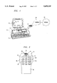
- FIG. 1 illustrates a computer, mouse and telephone network
- FIG. 2 is a top view of a multifunctional mouse
- FIG. 3 is a side view of a multifunctional mouse
- FIG. 4 is a block diagram of a multifunctional mouse
- FIG. 5 illustrates a display screen
- FIG. 6 illustrates a single icon with multiple active regions.
- FIG. 1 illustrates computer 10 which communicates with display 12 and keyboard 14.
- Mouse 16 is used to control the position of icon 18 that is displayed on display 12, to enter numerical data into computer 10 and to communicate using telephone network 20 through telephone network interface 22.
- mouse 16 communicates with computer 10 using a conductor and with telephone network interface 22 using infrared signals.
- FIGS. 2 and 3 are top and side views, respectively, of multifunctional mouse 16.
- the top surface of multifunctional mouse 16 includes keypad 40 which is composed of user activated switches or keys 42.
- the keys can be numbered in any particular order; however, it is desirable to have an arrangement of keys 42 similar to that of a typical telephone.
- Keys 44 and 46 are used to instruct computer 10 to change the way in which it interprets the activation of keys 42.
- Computer 10 interprets the activation of switches 42 in two ways depending on the way in which mouse 16 is to be used. If mouse 16 is to be used in a keypad mode, switches 42 are interpreted as a keypad, that is, the activation of keys labeled "1", “2", “3”, etc. are interpreted as the digits 1, 2, 3, etc., respectively. If mouse 16 is to be used in a conventional point and click mode, switches 42 are interpreted in the same manner as a conventional mouse, that is, the activation of keys labeled "1", "2" and “3" are interpreted as the left, center and right buttons, respectively, of a conventional mouse.
- Switches 48 and 50 are used when a user desires to communicate over telephone network 20. Switches or keys 48 and 50 are used to switch from an off-hook to an on-hook condition, or from an on-hook to an off-hook condition. A user switches between off-hook and on-hook conditions by simultaneously pressing keys 48 and 50. For example, to begin a telephone conversation, a user presses keys 48 and 50 to create an off-hook condition and to obtain a dial tone. When a user desires to end a telephone conversation, an on-hook condition is created by once again simultaneously pressing keys 48 and 50. It is also possible to control on-hook and off-hook conditions using only a single key; however, using two keys helps to prevent accidental switching between on-hook and off-hook conditions.
- a user's voice is transmitted to the telephone network using microphone 52.
- Microphone 52 is on the top surface of mouse 16; however, the microphone may be placed in any location that permits reception of the user's voice.
- Speakers 54 are located on the sides of mouse 16. It is also possible to locate one larger speaker on top surface 55 of mouse 16.
- Mouse 16 may communicate with computer 10 and network 20 using wired communication links, or wireless communication links.
- infrared light emitting diodes LEDs
- LED 58 is used to communicate with an infrared receiver in computer 10
- LED 60 is used to communicate with an infrared receiver in telephone network interface 22.
- LEDs 58 and 60 produce different wavelengths of infrared light.
- LED 58 uses a wavelength to which the receiver in computer 10 is sensitive and the receiver in network interface 22 is insensitive
- LED 60 uses a wavelength to which the receiver in telephone network interface 22 is sensitive and the receiver in computer 10 is insensitive.
- coding schemes that permit using the same wavelength for communications with both computer 10 and telephone network interface 22.
- Using a coding scheme makes it possible to use a single light emitting diode for communications.
- a wire or conductor to communicate between mouse 16 and computer 10, and/or between mouse 16 and telephone network interface 22. If a wire is to be used, it is desirable to use a wire for communications between mouse 16 and computer 10 while maintaining a wireless communication channel between mouse 16 and telephone network interface 22.
- mouse 16 contains ball 64 which is used to sense the motion of the mouse as it is moved across a surface. It is also possible for ball 64 to extend through the top surface of the mouse rather than the lower surface of the mouse. This will enable the mouse to be used as a track ball device in which the user rotates the ball to position an icon in a desirable location on display 12.
- the track ball embodiment of the invention offers the advantage of controlling the icon on display 12 without moving mouse 16 and thereby saves additional desktop space.
- FIG. 4 is a block diagram of multifunctional mouse 16.
- Position detection circuitry 90 monitors the motion of ball 64 to produce signals that computer 10 uses to control the position of an icon, such as a pointing icon, on display 12.
- Position detection circuitry is well-known in the art and uses, for example, rollers in contact with ball 64 so that the rollers rotate when ball 64 rotates as mouse 16 is moved along a surface.
- the rollers are positioned 90 degrees apart along the circumference of ball 64 so that one roller can detect rotation resulting from moving mouse 16 in the X direction, and the other roller can detect rotation resulting from moving mouse 16 in the Y direction.
- Each of the rollers is attached to a shaft that rotates a slotted disk, where the shafts are mounted at right angles to each other.
- the slotted disk interrupts a light beam between a light emitting diode and a photo transistor to create a signal indicative of ball 64's rotation.
- Computer 10 uses these signals to monitor the X and Y movements of mouse 16 and positions an icon on display 12 in a conventional manner in response to the movements of mouse 16.
- wireless interface 92 converts signals from position detection circuitry 90 into radio frequency or infrared signals that are received by a corresponding receiver in computer 10.
- These interfaces are well-known in the art and may be similar to, for example, a conventional infrared remote control interface used on a wireless mouse.
- Keypad 40, and keys 44 and 46 also communicate with computer 10, and when a wireless interface is used, they communicate via wireless interface 92. When a key is pressed, the identity of that key is passed to computer 10 in a conventional fashion. As mentioned earlier, when both keys 44 and 46 are pressed nearly simultaneously, computer 10 changes the way in which it interprets the inputs from mouse 16. In reference to FIG. 5, it is also possible to instruct computer 10 to interpret the inputs from mouse 16 as keypad inputs rather than conventional mouse inputs by positioning pointing icon 97, which is controlled by mouse 16, into predefined location 98 on display 12. When the icon is positioned within this location on display 12, inputs from mouse 16 are interpreted as keypad inputs rather than simple click and point inputs. It is also possible to control the way in which computer 10 interprets inputs from mouse 16 based on which software application is being executed by the computer.
- Keypad 40 is also connected to conventional telephone circuitry 100.
- Telephone circuitry 100 receives inputs from keypad 40 and microphone 52, and provides an output to speaker 54.
- Telephone circuitry 100 is well-known in the art and may be used to interface to telephone network 20, in a conventional wired manner using "tip" and "ring” lines.
- wireless interface 102 is used.
- Wireless interface 102 may be a conventional radio frequency interface such as those used in cordless telephones or it may be an infrared communication interface similar to those used in infrared remote control systems. If a wireless interface is used, the appropriate receiver is used as telephone network interface 22.
- interface 22 may be similar to a conventional cordless telephone base station when radio frequency communications are used, and interface 22 may be similar to a conventional infrared receiver when infrared communications are used.
- telephone circuitry 100 receives inputs from switches 48 and 50 via control 104. As discussed earlier, if an on-hook condition exists, pressing keys 48 and 50 nearly simultaneously will create an off-hook condition. If an off-hook condition exists, pressing keys 48 and 50 nearly simultaneously creates an on-hook condition. Control 104 indicates an off-hook or an on-hook condition to telephone circuitry 100. Control 104 may be implemented using an appropriately programmed microprocessor, or a simple state machine that switches between one of two states when inputs from keys 48 and 50 are detected.
- mouse 16 uses a conductor to communicate with computer 10, electrical power can be provided to mouse 16 via the conductor. If mouse 16 is used in a wireless configuration, battery 110 is used to provide electrical power to the circuitry located in mouse 16. When mouse 16 is used with wireless communications, it is desirable to have a "nest" that is used to charge battery 110 when the mouse is not in use.
- the icons are positioned in a manner that is representative of the arrangement of the keys composing keypad 40. This will enable the user to look at display 12 while operating the keys of keypad 40 on mouse 16.
- the icons representing the keys change appearance when the corresponding key is pressed on mouse 16 to indicate to the user that computer 10 has received a signal indicative of a key being pressed. This provides the user with visual feedback to indicate that the information is being received by computer 10 and also provides the advantage of permitting the user to use keypad 40 without looking back and forth between display 12 and mouse 16.
- the icons may have a one-to-one correspondence to the keys composing keypad 40.
- FIG. 6 illustrates single icon 120 which is representative of mouse 16.
- Icon 120 may be movable in a manner similar to that of a conventional pointing icon, where segment 122 is used as the pointing portion of the icon. If icon 120 is not movable, a conventional pointing icon may be used in addition to icon 120 for providing inputs to the computer. It is desirable for icon 120 to be relatively small with respect to the display screen in order to minimize the display area covered by the icon.
- Icon 120 includes several active regions that change appearance when the corresponding key of mouse 16 is activated. In this embodiment, active regions are provided for the keys composing keypad 40 and for keys 44, 46, 52 and 54.
- telephone circuitry 100 it is also possible to position telephone circuitry 100 within computer 10.
- information from keyboard 40 is passed to computer 10 for use by telephone circuitry 100.
- telephone circuitry 100 communicates directly with the microphone and speaker.
- telephone circuitry 100 communicates with the speaker and/or microphone over the communication channel between computer 10 and mouse 16.
- Placing telephone circuitry 100 in computer 10 offers the advantage of decreasing the number of communication channels to mouse 16 by eliminating the need for a communication channel that connects directly between mouse 16 and interface 22.
- telephone circuitry 100 communicates with interface 22 via a communication channel between computer 10 and interface 22.
Abstract
Description
Claims (17)
Priority Applications (4)
| Application Number | Priority Date | Filing Date | Title |
|---|---|---|---|
| US08/339,387 US5659335A (en) | 1994-11-14 | 1994-11-14 | Computing interface system |
| CA002158292A CA2158292C (en) | 1994-11-14 | 1995-09-14 | Computing interface system |
| EP95307806A EP0712066A1 (en) | 1994-11-14 | 1995-11-01 | Computing interface system |
| JP31853995A JP3361675B2 (en) | 1994-11-14 | 1995-11-14 | Computer interface system |
Applications Claiming Priority (1)
| Application Number | Priority Date | Filing Date | Title |
|---|---|---|---|
| US08/339,387 US5659335A (en) | 1994-11-14 | 1994-11-14 | Computing interface system |
Publications (1)
| Publication Number | Publication Date |
|---|---|
| US5659335A true US5659335A (en) | 1997-08-19 |
Family
ID=23328778
Family Applications (1)
| Application Number | Title | Priority Date | Filing Date |
|---|---|---|---|
| US08/339,387 Expired - Lifetime US5659335A (en) | 1994-11-14 | 1994-11-14 | Computing interface system |
Country Status (4)
| Country | Link |
|---|---|
| US (1) | US5659335A (en) |
| EP (1) | EP0712066A1 (en) |
| JP (1) | JP3361675B2 (en) |
| CA (1) | CA2158292C (en) |
Cited By (27)
| Publication number | Priority date | Publication date | Assignee | Title |
|---|---|---|---|---|
| US5847695A (en) * | 1996-01-04 | 1998-12-08 | Siemens Business Communication Systems, Inc. | Method and apparatus for implementing a dialpad on the surface of a mouse input device |
| US5943625A (en) * | 1995-08-31 | 1999-08-24 | Samsung Electronics Co., Ltd. | System having a dual-purpose telephone and mouse |
| US6229524B1 (en) * | 1998-07-17 | 2001-05-08 | International Business Machines Corporation | User interface for interaction with video |
| US6285354B1 (en) | 1998-11-30 | 2001-09-04 | Micron Technology, Inc. | Combination mouse and telephone handset |
| US6297807B1 (en) * | 1998-07-31 | 2001-10-02 | International Business Machines Corporation | Microphone sheath having pointing device and control buttons |
| US20010033267A1 (en) * | 1998-09-02 | 2001-10-25 | Darren Kim | Notebook computer with detachable infrared multi-mode input device |
| US6321281B1 (en) * | 1997-10-14 | 2001-11-20 | Nec Corporation | Pointing device with a controller for monitoring a protocol selector signal derived from a computer to select one of a compatibility function and an additional function |
| US6380714B1 (en) * | 2001-03-21 | 2002-04-30 | Shin Jiuh Corp. | Charger for wireless product |
| US6390423B1 (en) | 1998-12-04 | 2002-05-21 | Fellowes, Inc. | Ergonomic soft-feel mouse |
| US20030197680A1 (en) * | 2000-02-14 | 2003-10-23 | Davenport Anthony G. | Ergonomic side grip computer mouse |
| WO2003098591A1 (en) * | 2002-05-15 | 2003-11-27 | Samata Shah | Multi-functional device |
| US20040017350A1 (en) * | 2002-07-25 | 2004-01-29 | Samsung Electronics Co., Ltd. | Computer system and method of controlling the same |
| US6694391B2 (en) * | 2001-01-16 | 2004-02-17 | Dell Products L.P. | Combination computer mouse and telephony handset |
| US20050179665A1 (en) * | 2004-02-12 | 2005-08-18 | Wen-Hsiu Kuo | [multifunctional numberal keypad] |
| US20060040712A1 (en) * | 2004-08-23 | 2006-02-23 | Siemens Information And Communication Mobile, Llc | Hand-held communication device as pointing device |
| US20060287086A1 (en) * | 2002-07-27 | 2006-12-21 | Sony Computer Entertainment America Inc. | Scheme for translating movements of a hand-held controller into inputs for a system |
| US20070021208A1 (en) * | 2002-07-27 | 2007-01-25 | Xiadong Mao | Obtaining input for controlling execution of a game program |
| US20080100825A1 (en) * | 2006-09-28 | 2008-05-01 | Sony Computer Entertainment America Inc. | Mapping movements of a hand-held controller to the two-dimensional image plane of a display screen |
| US7850526B2 (en) | 2002-07-27 | 2010-12-14 | Sony Computer Entertainment America Inc. | System for tracking user manipulations within an environment |
| US7918733B2 (en) | 2002-07-27 | 2011-04-05 | Sony Computer Entertainment America Inc. | Multi-input game control mixer |
| US8570378B2 (en) | 2002-07-27 | 2013-10-29 | Sony Computer Entertainment Inc. | Method and apparatus for tracking three-dimensional movements of an object using a depth sensing camera |
| US8781151B2 (en) | 2006-09-28 | 2014-07-15 | Sony Computer Entertainment Inc. | Object detection using video input combined with tilt angle information |
| WO2015049184A1 (en) | 2013-10-01 | 2015-04-09 | Akzo Nobel Chemicals International B.V. | A methanol-based diesel fuel and the use of an ignition improver |
| US9174119B2 (en) | 2002-07-27 | 2015-11-03 | Sony Computer Entertainement America, LLC | Controller for providing inputs to control execution of a program when inputs are combined |
| US9393487B2 (en) | 2002-07-27 | 2016-07-19 | Sony Interactive Entertainment Inc. | Method for mapping movements of a hand-held controller to game commands |
| US10365735B2 (en) | 2003-10-08 | 2019-07-30 | Universal Electronics Inc. | Device that manages power provided to an object sensor |
| USRE48417E1 (en) | 2006-09-28 | 2021-02-02 | Sony Interactive Entertainment Inc. | Object direction using video input combined with tilt angle information |
Families Citing this family (3)
| Publication number | Priority date | Publication date | Assignee | Title |
|---|---|---|---|---|
| EP1921533A1 (en) * | 2006-11-10 | 2008-05-14 | Research In Motion Limited | Method of mapping a traditional touchtone telephone keypad on a handheld electronic device and associated apparatus |
| US7642934B2 (en) | 2006-11-10 | 2010-01-05 | Research In Motion Limited | Method of mapping a traditional touchtone keypad on a handheld electronic device and associated apparatus |
| CN101650615B (en) * | 2008-08-13 | 2011-01-26 | 怡利电子工业股份有限公司 | Automatic switching method of cursor controller and keyboard of push type touchpad |
Citations (12)
| Publication number | Priority date | Publication date | Assignee | Title |
|---|---|---|---|---|
| US3879722A (en) * | 1973-12-10 | 1975-04-22 | Bell Telephone Labor Inc | Interactive input-output computer terminal with automatic relabeling of keyboard |
| US5049863A (en) * | 1989-02-10 | 1991-09-17 | Kabushiki Kaisha Toshiba | Cursor key unit for a computer having a mouse function removably mounted on a keyboard section of a base |
| US5063376A (en) * | 1989-05-05 | 1991-11-05 | Chang Ronald G | Numeric mouse one hand controllable computer peripheral pointing device |
| US5157381A (en) * | 1990-04-23 | 1992-10-20 | Cheng San Yih | Computer mouse |
| US5164713A (en) * | 1991-10-15 | 1992-11-17 | Bain Lee L | Cursor position controller for use with mouse and display systems |
| US5195894A (en) * | 1991-05-15 | 1993-03-23 | Nimbus, Inc. | Braille mouse having character code member actuated by single solenoid |
| US5250929A (en) * | 1991-07-29 | 1993-10-05 | Conference Communications, Inc. | Interactive overlay-driven computer display system |
| US5268674A (en) * | 1992-01-31 | 1993-12-07 | Apple Computer, Inc. | Mechanically latching mouse button |
| US5280276A (en) * | 1992-07-10 | 1994-01-18 | Quickshot (Bvi) Ltd. | Combination mouse/trackball input device |
| US5287090A (en) * | 1992-09-30 | 1994-02-15 | Grant Alan H | Combination mouse and track ball unit |
| US5296871A (en) * | 1992-07-27 | 1994-03-22 | Paley W Bradford | Three-dimensional mouse with tactile feedback |
| EP0602840A1 (en) * | 1992-12-17 | 1994-06-22 | AT&T Corp. | Control of a computer using a telephone handset |
Family Cites Families (5)
| Publication number | Priority date | Publication date | Assignee | Title |
|---|---|---|---|---|
| JPS583020A (en) * | 1981-06-30 | 1983-01-08 | Yokogawa Hokushin Electric Corp | Multi-item input device |
| GB2131746B (en) * | 1982-10-21 | 1986-06-04 | Loke Kar Kohoon | Keyboards |
| FR2599163A1 (en) * | 1986-05-21 | 1987-11-27 | Bourgain Pierre | DATA INPUT DEVICE IN A COMPUTER SYSTEM |
| DE3700913A1 (en) * | 1987-01-14 | 1988-07-28 | Siemens Ag | Arrangement for selection of functions |
| GB9025286D0 (en) * | 1990-11-21 | 1991-01-02 | Smiths Industries Plc | Radar apparatus |
-
1994
- 1994-11-14 US US08/339,387 patent/US5659335A/en not_active Expired - Lifetime
-
1995
- 1995-09-14 CA CA002158292A patent/CA2158292C/en not_active Expired - Fee Related
- 1995-11-01 EP EP95307806A patent/EP0712066A1/en not_active Ceased
- 1995-11-14 JP JP31853995A patent/JP3361675B2/en not_active Expired - Fee Related
Patent Citations (12)
| Publication number | Priority date | Publication date | Assignee | Title |
|---|---|---|---|---|
| US3879722A (en) * | 1973-12-10 | 1975-04-22 | Bell Telephone Labor Inc | Interactive input-output computer terminal with automatic relabeling of keyboard |
| US5049863A (en) * | 1989-02-10 | 1991-09-17 | Kabushiki Kaisha Toshiba | Cursor key unit for a computer having a mouse function removably mounted on a keyboard section of a base |
| US5063376A (en) * | 1989-05-05 | 1991-11-05 | Chang Ronald G | Numeric mouse one hand controllable computer peripheral pointing device |
| US5157381A (en) * | 1990-04-23 | 1992-10-20 | Cheng San Yih | Computer mouse |
| US5195894A (en) * | 1991-05-15 | 1993-03-23 | Nimbus, Inc. | Braille mouse having character code member actuated by single solenoid |
| US5250929A (en) * | 1991-07-29 | 1993-10-05 | Conference Communications, Inc. | Interactive overlay-driven computer display system |
| US5164713A (en) * | 1991-10-15 | 1992-11-17 | Bain Lee L | Cursor position controller for use with mouse and display systems |
| US5268674A (en) * | 1992-01-31 | 1993-12-07 | Apple Computer, Inc. | Mechanically latching mouse button |
| US5280276A (en) * | 1992-07-10 | 1994-01-18 | Quickshot (Bvi) Ltd. | Combination mouse/trackball input device |
| US5296871A (en) * | 1992-07-27 | 1994-03-22 | Paley W Bradford | Three-dimensional mouse with tactile feedback |
| US5287090A (en) * | 1992-09-30 | 1994-02-15 | Grant Alan H | Combination mouse and track ball unit |
| EP0602840A1 (en) * | 1992-12-17 | 1994-06-22 | AT&T Corp. | Control of a computer using a telephone handset |
Non-Patent Citations (13)
| Title |
|---|
| DE A 37 00913 (Siemens AG) 28 Jul. 1988. * |
| DE-A-37 00913 (Siemens AG) 28 Jul. 1988. |
| EP A 0 246 971 Burgain Pierre Eedmond Gabriel; Morel EP Burgain Dominique Blanche, 25 Nov. 1987. * |
| EP A 0 487 219 Smiths Industries PLC May 27 1992. * |
| EP-A-0 246 971 Burgain Pierre Eedmond Gabriel; Morel EP Burgain Dominique Blanche, 25 Nov. 1987. |
| EP-A-0 487 219 Smiths Industries PLC May 27 1992. |
| European Search Report Mar. 5, 1996. * |
| IBM Technical Disclosure Bulletin, vol. 28, No. 6, 1 Nov. 1985, New York, US, pp. 2648 2649, Button Interface With Visual Cues . * |
| IBM Technical Disclosure Bulletin, vol. 28, No. 6, 1 Nov. 1985, New York, US, pp. 2648-2649, "Button Interface With Visual Cues". |
| Patent Abstracts of Japan, vol. 007 No. 073 P186 (1218), 25 Mar. 1983 * JP A 58 003020 (Hokushin Denki Seisakusho:KK) 8 Jan. 1983. * |
| Patent Abstracts of Japan, vol. 007 No. 073 P186 (1218), 25 Mar. 1983 * JP-A-58 003020 (Hokushin Denki Seisakusho:KK) 8 Jan. 1983. |
| UK Patent Application GB A 2 131 746 Loke Kar Kohoon 27 Jun. 1984. * |
| UK Patent Application GB-A-2 131 746 Loke Kar Kohoon 27 Jun. 1984. |
Cited By (50)
| Publication number | Priority date | Publication date | Assignee | Title |
|---|---|---|---|---|
| US5943625A (en) * | 1995-08-31 | 1999-08-24 | Samsung Electronics Co., Ltd. | System having a dual-purpose telephone and mouse |
| US5847695A (en) * | 1996-01-04 | 1998-12-08 | Siemens Business Communication Systems, Inc. | Method and apparatus for implementing a dialpad on the surface of a mouse input device |
| US6691189B2 (en) | 1997-10-14 | 2004-02-10 | Nec Corporation | Pointing device with a controller for monitoring a protocol selector signal derived from a computer to select one of a compatibility function and an additional function |
| US7003600B2 (en) | 1997-10-14 | 2006-02-21 | Nec Corporation | Pointing device with a controller used for monitoring a protocol selector signal derived from a computer to select one of a compatibility function and an additional function |
| US6321281B1 (en) * | 1997-10-14 | 2001-11-20 | Nec Corporation | Pointing device with a controller for monitoring a protocol selector signal derived from a computer to select one of a compatibility function and an additional function |
| US20040059849A1 (en) * | 1997-10-14 | 2004-03-25 | Reiji Fujikawa | Pointing device with a controller used for monitoring a protocol selector signal derived from a computer to select one of a compatibility function and an additional function |
| US6229524B1 (en) * | 1998-07-17 | 2001-05-08 | International Business Machines Corporation | User interface for interaction with video |
| US6297807B1 (en) * | 1998-07-31 | 2001-10-02 | International Business Machines Corporation | Microphone sheath having pointing device and control buttons |
| US20010033267A1 (en) * | 1998-09-02 | 2001-10-25 | Darren Kim | Notebook computer with detachable infrared multi-mode input device |
| US6424335B1 (en) | 1998-09-02 | 2002-07-23 | Fujitsu Limited | Notebook computer with detachable infrared multi-mode input device |
| US7298359B2 (en) | 1998-09-02 | 2007-11-20 | Fujitsu Limited | Notebook computer with detachable infrared multi-mode input device |
| US6285354B1 (en) | 1998-11-30 | 2001-09-04 | Micron Technology, Inc. | Combination mouse and telephone handset |
| US6390423B1 (en) | 1998-12-04 | 2002-05-21 | Fellowes, Inc. | Ergonomic soft-feel mouse |
| US20030197680A1 (en) * | 2000-02-14 | 2003-10-23 | Davenport Anthony G. | Ergonomic side grip computer mouse |
| US6828958B2 (en) * | 2000-02-14 | 2004-12-07 | Anthony G. Davenport | Ergonomic side grip computer mouse |
| US6694391B2 (en) * | 2001-01-16 | 2004-02-17 | Dell Products L.P. | Combination computer mouse and telephony handset |
| US6380714B1 (en) * | 2001-03-21 | 2002-04-30 | Shin Jiuh Corp. | Charger for wireless product |
| WO2003098591A1 (en) * | 2002-05-15 | 2003-11-27 | Samata Shah | Multi-functional device |
| US20040017350A1 (en) * | 2002-07-25 | 2004-01-29 | Samsung Electronics Co., Ltd. | Computer system and method of controlling the same |
| US7439958B2 (en) * | 2002-07-25 | 2008-10-21 | Samsung Electronics Co., Ltd. | Computer system and method of controlling the same via a remote controller used as a mouse |
| US8675915B2 (en) | 2002-07-27 | 2014-03-18 | Sony Computer Entertainment America Llc | System for tracking user manipulations within an environment |
| US8570378B2 (en) | 2002-07-27 | 2013-10-29 | Sony Computer Entertainment Inc. | Method and apparatus for tracking three-dimensional movements of an object using a depth sensing camera |
| US20060287086A1 (en) * | 2002-07-27 | 2006-12-21 | Sony Computer Entertainment America Inc. | Scheme for translating movements of a hand-held controller into inputs for a system |
| US10220302B2 (en) | 2002-07-27 | 2019-03-05 | Sony Interactive Entertainment Inc. | Method and apparatus for tracking three-dimensional movements of an object using a depth sensing camera |
| US9393487B2 (en) | 2002-07-27 | 2016-07-19 | Sony Interactive Entertainment Inc. | Method for mapping movements of a hand-held controller to game commands |
| US9381424B2 (en) | 2002-07-27 | 2016-07-05 | Sony Interactive Entertainment America Llc | Scheme for translating movements of a hand-held controller into inputs for a system |
| US7850526B2 (en) | 2002-07-27 | 2010-12-14 | Sony Computer Entertainment America Inc. | System for tracking user manipulations within an environment |
| US7854655B2 (en) * | 2002-07-27 | 2010-12-21 | Sony Computer Entertainment America Inc. | Obtaining input for controlling execution of a game program |
| US7918733B2 (en) | 2002-07-27 | 2011-04-05 | Sony Computer Entertainment America Inc. | Multi-input game control mixer |
| US20110086708A1 (en) * | 2002-07-27 | 2011-04-14 | Sony Computer Entertainment America Llc | System for tracking user manipulations within an environment |
| US20110118021A1 (en) * | 2002-07-27 | 2011-05-19 | Sony Computer Entertainment America Llc | Scheme for translating movements of a hand-held controller into inputs for a system |
| US20110118031A1 (en) * | 2002-07-27 | 2011-05-19 | Sony Computer Entertainment America Llc | Controller for providing inputs to control execution of a program when inputs are combined |
| US8303405B2 (en) * | 2002-07-27 | 2012-11-06 | Sony Computer Entertainment America Llc | Controller for providing inputs to control execution of a program when inputs are combined |
| US9174119B2 (en) | 2002-07-27 | 2015-11-03 | Sony Computer Entertainement America, LLC | Controller for providing inputs to control execution of a program when inputs are combined |
| US8313380B2 (en) | 2002-07-27 | 2012-11-20 | Sony Computer Entertainment America Llc | Scheme for translating movements of a hand-held controller into inputs for a system |
| US20070021208A1 (en) * | 2002-07-27 | 2007-01-25 | Xiadong Mao | Obtaining input for controlling execution of a game program |
| US11099668B2 (en) | 2003-10-08 | 2021-08-24 | Universal Electronics Inc. | Device that manages power provided to an object sensor |
| US11592914B2 (en) * | 2003-10-08 | 2023-02-28 | Universal Electronics Inc. | Device that manages power provided to an object sensor |
| US20220066575A1 (en) * | 2003-10-08 | 2022-03-03 | Universal Electronics Inc. | Device that manages power provided to an object sensor |
| US11209917B2 (en) * | 2003-10-08 | 2021-12-28 | Universal Electronics Inc. | Device that manages power provided to an object sensor |
| US10365735B2 (en) | 2003-10-08 | 2019-07-30 | Universal Electronics Inc. | Device that manages power provided to an object sensor |
| US10747342B2 (en) | 2003-10-08 | 2020-08-18 | Universal Electronics Inc. | Device that manages power provided to an object sensor |
| US20050179665A1 (en) * | 2004-02-12 | 2005-08-18 | Wen-Hsiu Kuo | [multifunctional numberal keypad] |
| US20060040712A1 (en) * | 2004-08-23 | 2006-02-23 | Siemens Information And Communication Mobile, Llc | Hand-held communication device as pointing device |
| US7366540B2 (en) | 2004-08-23 | 2008-04-29 | Siemens Communications, Inc. | Hand-held communication device as pointing device |
| US8310656B2 (en) | 2006-09-28 | 2012-11-13 | Sony Computer Entertainment America Llc | Mapping movements of a hand-held controller to the two-dimensional image plane of a display screen |
| USRE48417E1 (en) | 2006-09-28 | 2021-02-02 | Sony Interactive Entertainment Inc. | Object direction using video input combined with tilt angle information |
| US20080100825A1 (en) * | 2006-09-28 | 2008-05-01 | Sony Computer Entertainment America Inc. | Mapping movements of a hand-held controller to the two-dimensional image plane of a display screen |
| US8781151B2 (en) | 2006-09-28 | 2014-07-15 | Sony Computer Entertainment Inc. | Object detection using video input combined with tilt angle information |
| WO2015049184A1 (en) | 2013-10-01 | 2015-04-09 | Akzo Nobel Chemicals International B.V. | A methanol-based diesel fuel and the use of an ignition improver |
Also Published As
| Publication number | Publication date |
|---|---|
| CA2158292A1 (en) | 1996-05-15 |
| JPH08211998A (en) | 1996-08-20 |
| CA2158292C (en) | 1999-11-09 |
| EP0712066A1 (en) | 1996-05-15 |
| JP3361675B2 (en) | 2003-01-07 |
Similar Documents
| Publication | Publication Date | Title |
|---|---|---|
| US5659335A (en) | Computing interface system | |
| US5706031A (en) | Computing and telecommunications interface system | |
| US6518958B1 (en) | Electronic apparatus having plural entry switches | |
| US6664951B1 (en) | Mobile communication terminal equipment and touch panel switch used therein | |
| US6496181B1 (en) | Scroll select-activate button for wireless terminals | |
| US6377685B1 (en) | Cluster key arrangement | |
| US20040212597A1 (en) | Keypads for electrical devices | |
| EP1333363A2 (en) | Electronic device and control element | |
| US20050124387A1 (en) | Portable apparatus user interface | |
| KR20010071599A (en) | Head operated computer pointer | |
| KR20090046618A (en) | Portable terminal | |
| WO2002031807A1 (en) | Data entry device | |
| KR20030051665A (en) | Means for handheld functional apparatus | |
| KR20050065453A (en) | Soft keys for a mobile communications device having moveable panels | |
| US20060109239A1 (en) | Integrated module combining cursor control and numeric keypad | |
| GB2327558A (en) | Two-way communication apparatus having a touchpad-based user interface | |
| KR100762635B1 (en) | Key inputting device for portable communication device | |
| JP3840904B2 (en) | Electronics | |
| JP2003005905A (en) | Electronic equipment | |
| JP2001237941A (en) | Portable telephone equipment | |
| KR101161695B1 (en) | Integrated cellular phone, digital camera, and pda, with swivel mechanism providing access to the interface elements of each function | |
| KR20050091264A (en) | Pointing device for mobile communication terminal | |
| JP2001210962A (en) | Portable terminal and mobile telephone device | |
| KR20020038849A (en) | Mobile telecommunication terminal having touch pad and menu selection method thereof | |
| KR101058256B1 (en) | Mobile electronic device and operation detection method of mobile electronic device |
Legal Events
| Date | Code | Title | Description |
|---|---|---|---|
| AS | Assignment |
Owner name: AT&T CORP., NEW YORK Free format text: ASSIGNMENT OF ASSIGNORS INTEREST;ASSIGNOR:PARTRIDGE, B. WARING III;REEL/FRAME:007274/0518 Effective date: 19941107 |
|
| AS | Assignment |
Owner name: AT&T IPM CORP., FLORIDA Free format text: ASSIGNMENT OF ASSIGNORS INTEREST;ASSIGNOR:AT&T CORP.;REEL/FRAME:007467/0511 Effective date: 19950428 |
|
| AS | Assignment |
Owner name: LUCENT TECHNOLOGIES INC., NEW JERSEY Free format text: ASSIGNMENT OF ASSIGNORS INTEREST;ASSIGNOR:AT&T CORP.;REEL/FRAME:008488/0374 Effective date: 19960329 |
|
| STCF | Information on status: patent grant |
Free format text: PATENTED CASE |
|
| FEPP | Fee payment procedure |
Free format text: PAYOR NUMBER ASSIGNED (ORIGINAL EVENT CODE: ASPN); ENTITY STATUS OF PATENT OWNER: LARGE ENTITY |
|
| FPAY | Fee payment |
Year of fee payment: 4 |
|
| AS | Assignment |
Owner name: THE CHASE MANHATTAN BANK, AS COLLATERAL AGENT, TEX Free format text: CONDITIONAL ASSIGNMENT OF AND SECURITY INTEREST IN PATENT RIGHTS;ASSIGNOR:LUCENT TECHNOLOGIES INC. (DE CORPORATION);REEL/FRAME:011722/0048 Effective date: 20010222 |
|
| FPAY | Fee payment |
Year of fee payment: 8 |
|
| AS | Assignment |
Owner name: LUCENT TECHNOLOGIES INC., NEW JERSEY Free format text: TERMINATION AND RELEASE OF SECURITY INTEREST IN PATENT RIGHTS;ASSIGNOR:JPMORGAN CHASE BANK, N.A. (FORMERLY KNOWN AS THE CHASE MANHATTAN BANK), AS ADMINISTRATIVE AGENT;REEL/FRAME:018584/0446 Effective date: 20061130 |
|
| FPAY | Fee payment |
Year of fee payment: 12 |