US5673280A - Article comprising low noise optical fiber raman amplifier - Google Patents
Article comprising low noise optical fiber raman amplifier Download PDFInfo
- Publication number
- US5673280A US5673280A US08/600,354 US60035496A US5673280A US 5673280 A US5673280 A US 5673280A US 60035496 A US60035496 A US 60035496A US 5673280 A US5673280 A US 5673280A
- Authority
- US
- United States
- Prior art keywords
- amplifier
- fiber
- optical fiber
- length
- wavelength
- Prior art date
- Legal status (The legal status is an assumption and is not a legal conclusion. Google has not performed a legal analysis and makes no representation as to the accuracy of the status listed.)
- Expired - Lifetime
Links
Images


Classifications
-
- H—ELECTRICITY
- H04—ELECTRIC COMMUNICATION TECHNIQUE
- H04B—TRANSMISSION
- H04B10/00—Transmission systems employing electromagnetic waves other than radio-waves, e.g. infrared, visible or ultraviolet light, or employing corpuscular radiation, e.g. quantum communication
- H04B10/29—Repeaters
- H04B10/291—Repeaters in which processing or amplification is carried out without conversion of the main signal from optical form
- H04B10/2912—Repeaters in which processing or amplification is carried out without conversion of the main signal from optical form characterised by the medium used for amplification or processing
- H04B10/2916—Repeaters in which processing or amplification is carried out without conversion of the main signal from optical form characterised by the medium used for amplification or processing using Raman or Brillouin amplifiers
-
- H—ELECTRICITY
- H01—ELECTRIC ELEMENTS
- H01S—DEVICES USING THE PROCESS OF LIGHT AMPLIFICATION BY STIMULATED EMISSION OF RADIATION [LASER] TO AMPLIFY OR GENERATE LIGHT; DEVICES USING STIMULATED EMISSION OF ELECTROMAGNETIC RADIATION IN WAVE RANGES OTHER THAN OPTICAL
- H01S3/00—Lasers, i.e. devices using stimulated emission of electromagnetic radiation in the infrared, visible or ultraviolet wave range
- H01S3/30—Lasers, i.e. devices using stimulated emission of electromagnetic radiation in the infrared, visible or ultraviolet wave range using scattering effects, e.g. stimulated Brillouin or Raman effects
- H01S3/302—Lasers, i.e. devices using stimulated emission of electromagnetic radiation in the infrared, visible or ultraviolet wave range using scattering effects, e.g. stimulated Brillouin or Raman effects in an optical fibre
-
- H—ELECTRICITY
- H01—ELECTRIC ELEMENTS
- H01S—DEVICES USING THE PROCESS OF LIGHT AMPLIFICATION BY STIMULATED EMISSION OF RADIATION [LASER] TO AMPLIFY OR GENERATE LIGHT; DEVICES USING STIMULATED EMISSION OF ELECTROMAGNETIC RADIATION IN WAVE RANGES OTHER THAN OPTICAL
- H01S2301/00—Functional characteristics
- H01S2301/02—ASE (amplified spontaneous emission), noise; Reduction thereof
-
- H—ELECTRICITY
- H01—ELECTRIC ELEMENTS
- H01S—DEVICES USING THE PROCESS OF LIGHT AMPLIFICATION BY STIMULATED EMISSION OF RADIATION [LASER] TO AMPLIFY OR GENERATE LIGHT; DEVICES USING STIMULATED EMISSION OF ELECTROMAGNETIC RADIATION IN WAVE RANGES OTHER THAN OPTICAL
- H01S3/00—Lasers, i.e. devices using stimulated emission of electromagnetic radiation in the infrared, visible or ultraviolet wave range
- H01S3/05—Construction or shape of optical resonators; Accommodation of active medium therein; Shape of active medium
- H01S3/06—Construction or shape of active medium
- H01S3/063—Waveguide lasers, i.e. whereby the dimensions of the waveguide are of the order of the light wavelength
- H01S3/067—Fibre lasers
- H01S3/06754—Fibre amplifiers
- H01S3/06787—Bidirectional amplifier
-
- H—ELECTRICITY
- H01—ELECTRIC ELEMENTS
- H01S—DEVICES USING THE PROCESS OF LIGHT AMPLIFICATION BY STIMULATED EMISSION OF RADIATION [LASER] TO AMPLIFY OR GENERATE LIGHT; DEVICES USING STIMULATED EMISSION OF ELECTROMAGNETIC RADIATION IN WAVE RANGES OTHER THAN OPTICAL
- H01S3/00—Lasers, i.e. devices using stimulated emission of electromagnetic radiation in the infrared, visible or ultraviolet wave range
- H01S3/09—Processes or apparatus for excitation, e.g. pumping
- H01S3/091—Processes or apparatus for excitation, e.g. pumping using optical pumping
- H01S3/094—Processes or apparatus for excitation, e.g. pumping using optical pumping by coherent light
- H01S3/094003—Processes or apparatus for excitation, e.g. pumping using optical pumping by coherent light the pumped medium being a fibre
-
- Y—GENERAL TAGGING OF NEW TECHNOLOGICAL DEVELOPMENTS; GENERAL TAGGING OF CROSS-SECTIONAL TECHNOLOGIES SPANNING OVER SEVERAL SECTIONS OF THE IPC; TECHNICAL SUBJECTS COVERED BY FORMER USPC CROSS-REFERENCE ART COLLECTIONS [XRACs] AND DIGESTS
- Y10—TECHNICAL SUBJECTS COVERED BY FORMER USPC
- Y10S—TECHNICAL SUBJECTS COVERED BY FORMER USPC CROSS-REFERENCE ART COLLECTIONS [XRACs] AND DIGESTS
- Y10S372/00—Coherent light generators
- Y10S372/703—Optical isolater
Definitions
- This application pertains to optical fiber Raman amplifiers, and to optical fiber communication systems comprising such amplifiers.
- Erbium-doped optical fiber amplifiers are well known, and have reached a high level of development. However, these amplifiers are limited to wavelengths of about 1.5 ⁇ m. Indeed, at present there are no practical silica-based rare earth doped fiber amplifiers that can be used to provide gain at wavelengths of about 1.3 ⁇ m, the operating regime of most currently operating optical fiber communication systems. See, for instance, S. V. Chernikov et al., Electronics Letters, Vol. 31 (6), p. 472, (March 1995).
- Optical fiber Raman amplifiers are known, and can be designed to operate at a desired wavelength at or near 1.3 ⁇ m. See, for instance, S. V. Chernikov et al., op. cit. Indeed, Raman amplifiers are potentially promising candidates for such use because they can utilize silica-based fiber, and because of their high transparency when unpumped. For background information on stimulated Raman scattering see, for instance, "Nonlinear Fiber Optics", G. P. Agrawal, 2nd edition, Academic Press 1995, especially pages 16-19, and 316-335, incorporated herein by reference. See also U.S. Pat. No. 5,323,404, also incorporated herein by reference, which inter alia discloses fiber Raman amplifiers with a multiplicity of optical "cavities".
- RBS in optical fibers is well known. J. L. Gimlett et al., IEEE Photonics Technology Letters, Vol. 2 (3), p. 211 (March 1990) disclose that RBS " . . . can be modeled as a "Rayleigh mirror" which in lightwave systems with optical amplifiers has the same effect as a single discrete reflection with an effective reflectance given by (R bs / ⁇ 2), where R bs is the backscattering reflectance", and that optical isolation may be essential for fiber systems using high-gain optical amplifiers. See, for instance, p. 213, last paragraph. The reported measurements were obtained on a system comprising 30 m of Er-doped fiber between long lengths (120 km and 18 km, respectively) of optical fiber.
- the invention is embodied in an article that comprises a FRA which can have substantially improved noise properties, as compared to an analogous prior art FRA.
- the article is an optical fiber communication system, the system comprising a transmitter, a receiver that is spaced apart from the transmitter (typically hundreds or even thousands of kilometers apart), and an optical fiber transmission path that signal-transmissively connects the transmitter and the receiver.
- the transmission path comprises one or more FRAs according to the invention.
- the direction from transmitter to receiver is the "downstream” direction, and the opposite direction is the "upstream” direction.
- a point of the transmission path is "downstream" ("upstream") of another such point if the former lies in the downstream (upstream) direction from the latter.
- the article is an FRA according to the invention.
- An FRA comprises an input port (e.g., comprising a short length of fiber adapted for splicing to optical fiber), an output port (e.g., also comprising a short length of fiber), and an optical fiber path that signal-transmissively connects the input and output ports and comprises silica-based optical fiber (including Ge-doped and/or P-doped fiber), the fiber to be referred to as "amplifier fiber” because signal amplification by stimulated Raman scattering takes place in the fiber during amplifier operation.
- the FRA also comprises means for coupling pump radiation (of wavelength ⁇ p less than the signal wavelength ⁇ s ) into the amplifier fiber such that the pump radiation propagates in the amplifier fiber (in the upstream direction) towards the input port.
- the amplifier fiber comprises at least a first length L 1 and a second length L 2 of amplifier fiber, with the first length being disposed upstream of the second length.
- the FRA comprises an optical isolator disposed between the first and second lengths of amplifier fiber such that passage of radiation of wavelength ⁇ s from the second to the first length of amplifier fiber is substantially blocked.
- the means for coupling the pump radiation into the amplifier fiber are disposed to couple the pump radiation into the second length of amplifier fiber at or near the downstream end thereof, and the FRA further comprises wavelength-selective coupling means selected to facilitate passage of pump radiation from the second to the first length of amplifier fiber, by-passing the optical isolator.
- the first and second lengths together constitute essentially all of the amplifier fiber in a FRA according to the invention.
- a noise figure Associated with a FRA is a noise figure.
- the noise figure of an exemplary FRA according to the invention exemplarily is at least 2 dB, preferably at least 5 dB less than the noise figure of a comparison (prior art) FRA that differs from the inventive FRA only in having an undivided length of amplifier fiber of length L 1 +L 2 .
- the invention can also be embodied in a multistage FRA wherein each of the stages is separately pumped, e.g., by means of separate pump sources or, possibly, from a single pump source that is split into two or more beams.
- each of the stages is separately pumped, e.g., by means of separate pump sources or, possibly, from a single pump source that is split into two or more beams.
- it will frequently not be necessary to provide means for by-passing the optical isolator (or isolators).
- ⁇ s is about 1.3 ⁇ m, with ⁇ p exemplarily being about 1.24 ⁇ m.
- Optical isolators are well known and are commercially available, as are wavelength-selective coupling means.
- An example of the latter is a fused fiber coupler, conventionally referred to as a WDM.
- the length of the amplifier fiber in FRAs typically is in the range from a few hundreds of meters to several kilometers, exemplarily more than 200 m.
- the length of amplifier fibers in FRAs thus typically greatly exceeds that of EDFAs, which typically have amplifier fiber lengths in the range from a few meters to about hundred meters.
- This difference in amplifier fiber length between FRAs and EDFAs results in significant differences in noise characteristics between FRAs and EDFAs, with some noise-producing mechanisms that are important in FRAs being of no practical significance in EDFAs. Among these mechanisms are double RBS and Brillouin scattering in the amplifier fiber.
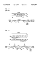
- FIG. 1 schematically depicts a prior art FRA, with a significant amount of double backscattered light co-propagating with the signal;
- FIG. 2 shows schematically an exemplary two-stage FRA according to the invention, with significantly reduced double backscattered light
- FIGS. 3-5 show the power spectrum of exemplary 1240 nm pump radiation, and of 1300 nm signal radiation amplified with co-propagating and counter-propagating pump radiation, respectively;
- FIGS. 6 and 7 show exemplary data on bit-error tests for a prior art one-stage Raman amplifier and a two-stage amplifier according to the invention.
- FIGS. 8-10 schematically show exemplary optical fiber communication systems according to the invention.
- FIG. 1 schematically shows a prior art (single stage) FRA 10, wherein numerals 11 to 13 refer to the undivided amplifier fiber of length L, and the upstream and downstream WDMs, respectively.
- Arrow 14 refers to the signal that propagates through the FRA
- 15 refers to double backscattered light that co-propagates with the signal, with the relatively large size of ellipse 151 intended to indicate a relatively large amount of amplified double backscattered radiation.
- Double RBS light is twice backscattered by unavoidable density fluctuations in the amplifier fiber such that it propagates in the downstream direction and adds noise to the signal. Although the amplitude of RBS light is generally small, the light is amplified in the same way the signal is amplified in the FRA, resulting in significant noise amplitude.
- a further noise mechanism that is typically insignificant in EDFAs but can be significant in FRAs is Brillouin scattering.
- the amplified signal couples to an acoustic phonon in the fiber and generates a counter-propagating wave, thereby reducing the signal amplitude. If the Brillouin scattered light experiences in the amplifier fiber a second reflection (e.g., due to Rayleigh scattering), the twice-scattered (and amplified) light will again interfere with the signal, thereby degrading the amplifier's performance.
- FIG. 2 schematically depicts an exemplary FRA 20 according to the invention.
- Numerals 21 and 22 refer to the first and second amplifier stages, respectively, and numerals 23 and 24 refer to the first and second amplifier fibers, respectively.
- Numerals 25-28 refer to the interstage optical isolator, the upstream and downstream interstage WDMs, and the fiber that shunts pump radiation around isolator 25.
- the lengths of the first and second amplifier fibers are not necessarily equal. Exemplarily, they are chosen such that each stage produces a gain of G/2 dB, the gain of the combination thus being G dB, e.g., 20 dB or more.
- FIG. 2 also shows signal 14, light 291 that has undergone double RBS in the upstream amplifier fiber, and light 292 that has undergone double RBS in the downstream amplifier fiber.
- the two-stage FRA of the invention adds considerably less than does an analogous than does an analogous single stage prior art FRA that differs from the former only in having an undivided amplifier fiber of length L, (i.e., without WDMs 26 and 27, isolator 25 and by-pass fiber 28).
- FIG. 3 shows the RF power spectrum of an exemplary 1240 nm Raman pump laser.
- the large noise spikes are caused by beating of the longitudinal laser modes, and are substantially unavoidable, due to the necessity of lasing on many longitudinal modes in order to prevent Brillouin scattering of the pump radiation.
- FIG. 4 shows the RF power spectrum of 1300 nm signal radiation after amplification by co-propagating Raman pump radiation, and clearly demonstrates that noise spikes from the pump radiation are transferred to the signal.
- FIG. 5 shows the RF power spectrum of the 1300 nm signal after amplification by counter-propagating pump radiation.
- the spectrum is free of pump noise spikes. This clearly establishes the advantage of counter-propagating Raman pumping.
- multi-path interference due to double RBS is typically the dominant source of noise.
- an effective technique for decreasing double RBS is provision of a multistage Raman amplifier, with an interstage optical isolator between adjacent stages.
- a multistage Raman amplifier with interstage isolator also increases the threshold for Brillouin scattering. Brillouin scattered light is generated only in the backwards propagating direction. Thus, any Brillouin scattered light generated in the second (downstream) stage of such a multistage Raman amplifier is absorbed by the interstage isolator.
- FIGS. 6 and 7 provide comparative data for a prior an single stage Raman amplifier and a multistage Raman amplifier according to the invention, respectively. While generating a gain of 19 dB, the prior art amplifier created a power penalty of 7 dB at 10 -9 BER (bit error rate), as shown by FIG. 6. In contrast, an analogous 2-stage amplifier according to the invention generated gains as large as 26 dB with essentially no power penalty, as demonstrated by FIG. 7. Both amplifiers used a counter-propagating pump geometry, and all measurements were taken at 2.5 Gb/s.
- Optical fiber communication systems according to the invention can take a variety of forms.
- a FRA according to the invention can serve as a power amplifier disposed close to the transmitter, it can serve as a pre-amplifier disposed close to the receiver, or it can be disposed between transmitter and receiver, spaced by a substantial distance (e.g., 100 km) from the closer of the two.
- An example of the latter is an upgraded 1.3 ⁇ m optical fiber communication system wherein FRAs according to the invention are used to replace conventional opto-electronic repeaters.
- FIG. 8 schematically depicts an optical fiber communication system 80 according to the invention, wherein numerals 81-84 refer, respectively, to transmitter, receiver, FRA according to the invention, and optical transmission fiber.
- FIG. 9 schematically shows another exemplary embodiment of the invention, namely, a multi-receiver communication system 90, wherein an FRA according to the invention serves as power amplifier that facilitates provision of a signal (exemplarily an analog signal, e.g., a CATV signal) to a multiplicity of receivers (subscribers).
- Numerals 91-94 refer, respectively, to transmitter, transmission fiber, FRA and splitter. Further amplifiers may be disposed between the transmitter and the FRA but are not shown.
- Splitter 94 divides the amplified signal into n signals that respectively propagate through fibers 951-95n to receivers 961-96n (of which only 962 is shown).
- FIG. 10 schematically depicts a further embodiment of the invention, namely, a remotely pumped communication system 100.
- the terminals are situated on land (e.g., on a first and a second island), and the fiber transmission path that links the terminals is under the sea.
- the system comprises transmitter 101 and receiver 110.
- Optional power amplifier 102 e.g., an EDFA
- a length of Er-doped optical fiber 104 is connected between fibers 103 and 105.
- Pump source 111 e.g, a cascaded Raman fiber laser
- Pump radiation of a wavelength (e.g., 1480 nm) suitable for pumping Er-doped fiber 104.
- the pump radiation is coupled into fiber 105 by conventional means (e.g., WDM 112), and propagates in upstream direction towards the Er-doped fiber.
- optical isolator 106 At an appropriate point between receiver and Er-doped fiber (e.g., about halfway) is disposed optical isolator 106, with WDMs 108 and 109 and fiber 107 enabling the pump radiation to by-pass the isolator, and to proceed through remaining fiber 105 to Er-doped fiber 104.
- radiation of wavelength 1480 nm not only can serve as pump for a conventional EDFA but also can serve as pump for a silica-based FRA.
- section 113 of the fiber communication system of FIG. 10 constitutes a FRA according to the invention, providing gain to the signal. In effect, section 113 serves as a distributed, relatively low noise, pre-amplifier for receiver 110.
- an optical fiber amplifier e.g., an amplifier according to the invention. This can be accomplished, for instance, by provision of an interstage filter with wavelength-dependent transmission characteristics, or by tailoring of the pump spectrum, e.g., by provision of a filter with wavelength-dependent transmission characteristics in the cavity of the laser or between the pump laser and the fiber amplifier.
- a FRA substantially as shown in FIG. 2 was assembled and tested.
- the exemplary amplifier contained three commercially available 1.3 ⁇ m polarization-insensitive isolators, one disposed just upstream of WDM 12, one disposed between the amplifier stages as shown in FIG. 2, and one disposed just downstream of WDM 13.
- WDMs 12, 13, 26 and 27 were commercially available 1240 nm:1310 nm fused fiber couplers.
- the amplifier was pumped with the output of a 1240 nm cascaded Raman laser which was pumped with the output of a 1060 nm cladding-pumped Nd fiber laser.
- the FRA was tested in conventional manner. Signal radiation of wavelength 1310 nm was coupled into the input port, and amplified signal radiation was received at the output port.
- the results were compared to a one-stage amplifier that differed from the IRA according to the invention only with respect to elements 25-28 of FIG. 2, with the 2-stage amplifier transformed into the 1-stage (comparison) amplifier by removal of the designated elements, and conventionally coupling fiber 24 to fiber 23. Bit-error-rate tests of both amplifiers were performed. Exemplary results are shown in FIGS. 6 and 7.
- the 1-stage FRA generated 19 dB net gain while introducing a power penalty of 7 dB, whereas the 2-stage FRA according to the invention generated up to 26 dB of net gain without introducing a power penalty.
Abstract
Description
Claims (12)
Priority Applications (4)
| Application Number | Priority Date | Filing Date | Title |
|---|---|---|---|
| US08/600,354 US5673280A (en) | 1996-02-12 | 1996-02-12 | Article comprising low noise optical fiber raman amplifier |
| JP9007393A JP3025210B2 (en) | 1996-02-12 | 1997-01-20 | Apparatus including optical fiber Raman amplifier |
| DE69700572T DE69700572T2 (en) | 1996-02-12 | 1997-02-04 | Low noise fiber optic Raman amplifier and fiber optic communication system with such an amplifier |
| EP97300692A EP0789432B1 (en) | 1996-02-12 | 1997-02-04 | Low noise optical fiber raman amplifier and communication system comprising such an amplifier |
Applications Claiming Priority (1)
| Application Number | Priority Date | Filing Date | Title |
|---|---|---|---|
| US08/600,354 US5673280A (en) | 1996-02-12 | 1996-02-12 | Article comprising low noise optical fiber raman amplifier |
Publications (1)
| Publication Number | Publication Date |
|---|---|
| US5673280A true US5673280A (en) | 1997-09-30 |
Family
ID=24403270
Family Applications (1)
| Application Number | Title | Priority Date | Filing Date |
|---|---|---|---|
| US08/600,354 Expired - Lifetime US5673280A (en) | 1996-02-12 | 1996-02-12 | Article comprising low noise optical fiber raman amplifier |
Country Status (4)
| Country | Link |
|---|---|
| US (1) | US5673280A (en) |
| EP (1) | EP0789432B1 (en) |
| JP (1) | JP3025210B2 (en) |
| DE (1) | DE69700572T2 (en) |
Cited By (94)
| Publication number | Priority date | Publication date | Assignee | Title |
|---|---|---|---|---|
| US5778014A (en) * | 1996-12-23 | 1998-07-07 | Islam; Mohammed N. | Sagnac raman amplifiers and cascade lasers |
| US5815518A (en) * | 1997-06-06 | 1998-09-29 | Lucent Technologies Inc. | Article comprising a cascaded raman fiber laser |
| US5920423A (en) * | 1997-12-05 | 1999-07-06 | Sdl, Inc. | Multiple pumped fiber amplifiers for WDM communication systems with adjustment for the amplifier signal gain bandwidth |
| WO1999050941A1 (en) * | 1998-04-01 | 1999-10-07 | Randwidth Solutions, Inc. | Broadband sagnac raman amplifiers and cascade lasers |
| US5991069A (en) * | 1998-01-22 | 1999-11-23 | Tyco Submarine Systems, Ltd. | Split-pumped dual stage optical fiber amplifier |
| US5995277A (en) * | 1997-06-30 | 1999-11-30 | Samsung Electronics Co., Ltd. | Optical fiber amplifier with absorber |
| US6081366A (en) * | 1997-08-28 | 2000-06-27 | Lucent Technologies Inc. | Optical fiber communication system with a distributed Raman amplifier and a remotely pumped er-doped fiber amplifier |
| US6181464B1 (en) * | 1998-12-01 | 2001-01-30 | Tycom (Us) Inc. | Low noise Raman amplifier employing bidirectional pumping and an optical transmission system incorporating same |
| US6236498B1 (en) | 1998-02-20 | 2001-05-22 | Sdl, Inc. | Upgradable, gain flattened fiber amplifiers for WDM applications |
| US6236487B1 (en) * | 1998-07-21 | 2001-05-22 | Corvis Corporation | Optical communication control system |
| US6310716B1 (en) * | 2000-08-18 | 2001-10-30 | Corning Incorporated | Amplifier system with a discrete Raman fiber amplifier module |
| US6335820B1 (en) * | 1999-12-23 | 2002-01-01 | Xtera Communications, Inc. | Multi-stage optical amplifier and broadband communication system |
| US6344925B1 (en) | 2000-03-03 | 2002-02-05 | Corvis Corporation | Optical systems and methods and optical amplifiers for use therein |
| US6347007B1 (en) * | 1997-02-19 | 2002-02-12 | Sdl, Inc. | Semiconductor laser high power amplifier system |
| US6356384B1 (en) | 1998-03-24 | 2002-03-12 | Xtera Communications Inc. | Broadband amplifier and communication system |
| US6359725B1 (en) * | 1998-06-16 | 2002-03-19 | Xtera Communications, Inc. | Multi-stage optical amplifier and broadband communication system |
| US6366729B1 (en) * | 1999-07-05 | 2002-04-02 | Alcatel | Limitation of oscillation caused by Raman amplification due to the use of different fibers |
| US6374006B1 (en) | 1998-03-20 | 2002-04-16 | Xtera Communications, Inc. | Chirped period gratings for raman amplification in circulator loop cavities |
| US6384963B2 (en) * | 2000-03-03 | 2002-05-07 | Lucent Technologies Inc. | Optical communication system with co-propagating pump radiation for raman amplification |
| US6396623B1 (en) | 2000-12-19 | 2002-05-28 | Onetta, Inc. | Wide-band optical amplifiers with interleaved gain stages |
| US6417965B1 (en) | 2001-02-16 | 2002-07-09 | Onetta, Inc. | Optical amplifier control system |
| US6417958B1 (en) | 2001-01-24 | 2002-07-09 | Lucent Technologies Inc. | WDM optical communication system using co-propagating Raman amplification |
| US6417959B1 (en) | 2000-12-04 | 2002-07-09 | Onetta, Inc. | Raman fiber amplifier |
| US6424457B1 (en) | 2000-10-06 | 2002-07-23 | Onetta, Inc. | Optical amplifiers and methods for manufacturing optical amplifiers |
| US6433920B1 (en) | 2000-04-27 | 2002-08-13 | Jds Uniphase Corporation | Raman-based utility optical amplifier |
| US6433922B1 (en) | 2001-02-26 | 2002-08-13 | Redc Optical Networks Ltd. | Apparatus and method for a self adjusting Raman amplifier |
| US6433921B1 (en) | 2001-01-12 | 2002-08-13 | Onetta, Inc. | Multiwavelength pumps for raman amplifier systems |
| US6434172B1 (en) | 1999-08-06 | 2002-08-13 | Fitel Usa Corp. | Article comprising a fiber raman device |
| US6441950B1 (en) | 2000-11-03 | 2002-08-27 | Onetta, Inc. | Distributed raman amplifier systems with transient control |
| US20020126714A1 (en) * | 2001-02-07 | 2002-09-12 | Hong Po | Raman fiber laser |
| US6456426B1 (en) | 2001-06-28 | 2002-09-24 | Onetta, Inc. | Raman amplifiers with modulated pumps |
| US20020159133A1 (en) * | 2001-02-02 | 2002-10-31 | The Furukawa Electric Co., Ltd. | Pump light source for raman amplifier and raman amplifier using the same |
| US6480326B2 (en) | 2000-07-10 | 2002-11-12 | Mpb Technologies Inc. | Cascaded pumping system and method for producing distributed Raman amplification in optical fiber telecommunication systems |
| US20020176133A1 (en) * | 1999-10-22 | 2002-11-28 | Corvis Corporation | Method of adjusting power for a wavelength-division multiplexed optical transmission system |
| US6490077B1 (en) | 2000-11-20 | 2002-12-03 | Corning Incorporated | Composite optical amplifier |
| US6507430B2 (en) * | 2001-02-23 | 2003-01-14 | Photon X, Inc. | Long wavelength optical amplifier |
| US6522459B1 (en) | 2001-02-22 | 2003-02-18 | Onetta, Inc. | Temperature control and monitoring of optical detector components in an optical communication system |
| US6532101B2 (en) | 2001-03-16 | 2003-03-11 | Xtera Communications, Inc. | System and method for wide band Raman amplification |
| US20030063373A1 (en) * | 2000-01-14 | 2003-04-03 | The Furukawa Electric Co., Ltd. | Raman amplifier |
| US6556345B1 (en) | 2001-06-21 | 2003-04-29 | Onetta, Inc. | Optical network equipment with control and data paths |
| US6567430B1 (en) | 1998-09-21 | 2003-05-20 | Xtera Communications, Inc. | Raman oscillator including an intracavity filter and amplifiers utilizing same |
| US6567207B1 (en) | 1999-05-12 | 2003-05-20 | Corvis Corporation | Optical transmission systems and optical amplifiers for use therein |
| US6574037B2 (en) | 1998-06-16 | 2003-06-03 | Xtera Communications, Inc. | All band amplifier |
| US6577789B1 (en) | 2001-09-26 | 2003-06-10 | Onetta, Inc. | Double-pass optical amplifiers and optical network equipment |
| US6587259B2 (en) | 2001-07-27 | 2003-07-01 | Xtera Communications, Inc. | System and method for controlling noise figure |
| US20030123141A1 (en) * | 2001-11-19 | 2003-07-03 | Aydin Yeniay | L band optical amplifier |
| US6594071B1 (en) | 2001-10-02 | 2003-07-15 | Xtera Communications, Inc. | Method and apparatus for amplifier control |
| US6600592B2 (en) | 1998-03-24 | 2003-07-29 | Xtera Communications, Inc. | S+ band nonlinear polarization amplifiers |
| US6611370B2 (en) | 1999-07-23 | 2003-08-26 | The Furukawa Electric Co., Ltd. | Raman amplifier system, apparatus and method for identifying, obtaining and maintaining an arbitrary Raman amplification performance |
| US20030169481A1 (en) * | 2002-03-07 | 2003-09-11 | Hwang Seong-Taek | Dispersion-compensated erbium-doped fiber amplifier |
| US6621619B2 (en) | 2001-07-30 | 2003-09-16 | The United States Of America As Represented By The Secretary Of The Navy | Hybrid brillouin/erbium doped fiber amplifier apparatus and method |
| US6624927B1 (en) | 2001-03-14 | 2003-09-23 | Onetta, Inc. | Raman optical amplifiers |
| US6625347B1 (en) | 2001-01-12 | 2003-09-23 | Onetta, Inc. | Pumps for Raman amplifier systems |
| US6631025B2 (en) | 2000-01-12 | 2003-10-07 | Xtera Communications, Inc. | Low-noise distributed Raman amplifier using bi-directional pumping using multiple Raman orders |
| US6633697B2 (en) | 1999-05-31 | 2003-10-14 | Ther Furukawa Electric Co., Ltd. | Raman amplification method and optical signal transmission method using same |
| US6633430B1 (en) | 2001-02-15 | 2003-10-14 | Onetta, Inc. | Booster amplifier with spectral control for optical communications systems |
| US6636344B2 (en) | 1998-07-23 | 2003-10-21 | The Furukawa Electric Co., Ltd. | Raman amplifier, optical repeater, and raman amplification method |
| US20030210457A1 (en) * | 2002-03-15 | 2003-11-13 | The Furukawa Electric Co., Ltd. | Tunable multimode wavelength division multiplex raman pump and amplifier, and a system, method, and computer program product for controlling tunable raman pumps, and raman amplifiers |
| US6657774B1 (en) * | 2000-08-18 | 2003-12-02 | Corning Incorporated | Amplifier system with distributed and discrete Raman fiber amplifiers |
| US6687049B1 (en) | 2001-07-03 | 2004-02-03 | Onetta, Inc. | Optical amplifiers with stable output power under low input power conditions |
| US6690507B2 (en) * | 2002-01-30 | 2004-02-10 | Corning Incorporated | Double-pumped raman amplifier |
| US6697558B2 (en) | 2000-03-03 | 2004-02-24 | Fitel U.S.A. Corp | Raman amplified optical system with reduction of four-wave mixing effects |
| US20040042061A1 (en) * | 2002-08-30 | 2004-03-04 | Islam Mohammed N. | Controlling ASE in optical amplification stages implementing time modulated pump signals |
| US20040066550A1 (en) * | 2002-10-02 | 2004-04-08 | Jay Paul R. | Optical pulse reshaping system |
| US6760148B2 (en) | 1998-03-24 | 2004-07-06 | Xtera Communications, Inc. | Nonlinear polarization amplifiers in nonzero dispersion shifted fiber |
| US6760509B2 (en) | 2000-02-14 | 2004-07-06 | The Regents Of The University Of Michigan | SNR booster for WDM systems |
| US6768577B2 (en) | 2002-03-15 | 2004-07-27 | Fitel Usa Corp. | Tunable multimode laser diode module, tunable multimode wavelength division multiplex raman pump, and amplifier, and a system, method, and computer program product for controlling tunable multimode laser diodes, raman pumps, and raman amplifiers |
| US6778321B1 (en) | 2002-03-15 | 2004-08-17 | Xtera Communications, Inc. | Fiber optic transmission system for a metropolitan area network |
| US6778320B1 (en) | 2000-11-20 | 2004-08-17 | Avanex Corporation | Composite optical amplifier |
| US6781748B2 (en) | 2001-09-28 | 2004-08-24 | Photon-X, Llc | Long wavelength optical amplifier |
| US6782199B1 (en) | 2000-09-29 | 2004-08-24 | Onetta, Inc. | Optical communications systems with optical subsystem communications links |
| US20040179797A1 (en) * | 2001-07-02 | 2004-09-16 | Hong Po | Multi-wavelength optical fiber |
| US20040208586A1 (en) * | 2002-03-27 | 2004-10-21 | Susumu Kinoshita | System and method for amplifying signals in an optical network |
| US20040207911A1 (en) * | 1995-03-20 | 2004-10-21 | Susumu Kinoshita | Optical fiber amplifier and dispersion compensating fiber module for optical fiber amplifier |
| US6810214B2 (en) | 2001-03-16 | 2004-10-26 | Xtera Communications, Inc. | Method and system for reducing degradation of optical signal to noise ratio |
| US20040213510A1 (en) * | 1999-10-22 | 2004-10-28 | Corvis Corporation | Optical fiber transmission system using RZ pulses |
| US6819479B1 (en) | 2001-12-20 | 2004-11-16 | Xtera Communications, Inc. | Optical amplification using launched signal powers selected as a function of a noise figure |
| US6819478B1 (en) | 2002-03-15 | 2004-11-16 | Xtera Communications, Inc. | Fiber optic transmission system with low cost transmitter compensation |
| US6825973B1 (en) | 2002-03-15 | 2004-11-30 | Xtera Communications, Inc. | Reducing leading edge transients using co-propagating pumps |
| US20040240043A1 (en) * | 2001-08-03 | 2004-12-02 | Demidov Andrey A. | Optical fiber amplifier |
| US6850360B1 (en) | 2001-04-16 | 2005-02-01 | Bookham, Inc. | Raman amplifier systems with diagnostic capabilities |
| US20050046929A1 (en) * | 1998-07-21 | 2005-03-03 | Corvis Corporation | Optical transmission systems including signal varying devices and methods |
| US6885498B2 (en) | 1998-06-16 | 2005-04-26 | Xtera Communications, Inc. | Multi-stage optical amplifier and broadband communication system |
| US20050105165A1 (en) * | 2003-09-08 | 2005-05-19 | The Furukawa Electric Co., Ltd. | Raman amplifier, pump source for use in a raman amplifier and method for amplifying an optical signal |
| US20050213985A1 (en) * | 1999-05-24 | 2005-09-29 | Corvis Corporation | Optical transmission systems including optical amplifiers and methods of use therein |
| US20050259325A1 (en) * | 2002-04-24 | 2005-11-24 | Silvia Ghidini | Optical devices comprising series of birefringent waverplates |
| US6985283B1 (en) | 1998-06-16 | 2006-01-10 | Xtera Communications, Inc. | Fiber-optic compensation for dispersion, gain tilt, and band pump nonlinearity |
| US7058311B1 (en) | 2002-03-15 | 2006-06-06 | Xtera Communications, Inc. | System and method for dispersion compensation in an optical communication system |
| US20060158717A1 (en) * | 2002-12-19 | 2006-07-20 | Marco De Donno | Multiple stage raman optical amplifier |
| US7197245B1 (en) | 2002-03-15 | 2007-03-27 | Xtera Communications, Inc. | System and method for managing system margin |
| CN1324395C (en) * | 2001-10-29 | 2007-07-04 | 李东翰 | Hybrid optical amplifier coupling raman fiber amplifier and semiconductor optical amplifier |
| US7277610B2 (en) | 2001-05-15 | 2007-10-02 | Nufern | Optical fiber and system containing same |
| US20090046746A1 (en) * | 2007-07-06 | 2009-02-19 | Deep Photonics Corporation | Pulsed fiber laser |
| US10386247B2 (en) * | 2016-09-29 | 2019-08-20 | Ofs Fitel, Llc | Extending a range of an optical fiber distributed sensing system |
Families Citing this family (13)
| Publication number | Priority date | Publication date | Assignee | Title |
|---|---|---|---|---|
| WO1998036479A1 (en) * | 1997-02-18 | 1998-08-20 | Nippon Telegraph And Telephone Corporation | Optical amplifier and transmission system using the same |
| FR2794912A1 (en) * | 1999-06-10 | 2000-12-15 | Cit Alcatel | RAMAN HYBRID AMPLIFIER |
| FR2799056B1 (en) * | 1999-07-05 | 2002-09-06 | Cit Alcatel | REMOTE RAMAN AMPLIFICATION |
| DE60004935T2 (en) * | 1999-07-08 | 2004-07-22 | Alcatel | Isolator use to overcome Raman gain limitations caused by Rayleigh scattering |
| DE10012881B4 (en) * | 2000-03-16 | 2008-09-04 | Nokia Siemens Networks Gmbh & Co.Kg | Raman amplifier system |
| US6898351B2 (en) * | 2000-11-07 | 2005-05-24 | Photon-X, Llc | Optical fiber transmission systems with suppressed light scattering |
| US6879434B2 (en) * | 2002-07-11 | 2005-04-12 | Fujitsu Network Communications, Inc. | Distributed raman amplifier for optical network and method |
| JP4532061B2 (en) * | 2002-09-24 | 2010-08-25 | 古河電気工業株式会社 | Waveform shaper, optical pulse generator, and optical regeneration system |
| FR2853092A1 (en) * | 2003-03-31 | 2004-10-01 | France Telecom | OPTICAL DEVICE, IN PARTICULAR FOR SUPPRESSING NOISE, known as RAYLEIGH DOUBLE BACK BROADCAST, AND INSTALLATION COMPRISING SUCH A DEVICE |
| ATE323349T1 (en) | 2003-06-19 | 2006-04-15 | Cit Alcatel | OPTICAL AMPLIFIER, TRANSMISSION SYSTEM AND METHOD FOR OPTIMIZATION |
| US7483636B2 (en) * | 2003-07-28 | 2009-01-27 | Fujitsu Limited | Optical network with sub-band rejection and bypass |
| JP2005134628A (en) * | 2003-10-30 | 2005-05-26 | Nippon Telegr & Teleph Corp <Ntt> | Optical transmission system and raman amplifier |
| CN103441417B (en) * | 2013-09-17 | 2015-12-23 | 电子科技大学 | A kind of Novel multi-wavelength Brillouin-Raman fiber laser |
Citations (2)
| Publication number | Priority date | Publication date | Assignee | Title |
|---|---|---|---|---|
| US4782491A (en) * | 1987-04-09 | 1988-11-01 | Polaroid Corporation | Ion doped, fused silica glass fiber laser |
| US5323404A (en) * | 1993-11-02 | 1994-06-21 | At&T Bell Laboratories | Optical fiber laser or amplifier including high reflectivity gratings |
Family Cites Families (1)
| Publication number | Priority date | Publication date | Assignee | Title |
|---|---|---|---|---|
| US5430572A (en) * | 1993-09-30 | 1995-07-04 | At&T Corp. | High power, high gain, low noise, two-stage optical amplifier |
-
1996
- 1996-02-12 US US08/600,354 patent/US5673280A/en not_active Expired - Lifetime
-
1997
- 1997-01-20 JP JP9007393A patent/JP3025210B2/en not_active Expired - Fee Related
- 1997-02-04 DE DE69700572T patent/DE69700572T2/en not_active Expired - Fee Related
- 1997-02-04 EP EP97300692A patent/EP0789432B1/en not_active Expired - Lifetime
Patent Citations (2)
| Publication number | Priority date | Publication date | Assignee | Title |
|---|---|---|---|---|
| US4782491A (en) * | 1987-04-09 | 1988-11-01 | Polaroid Corporation | Ion doped, fused silica glass fiber laser |
| US5323404A (en) * | 1993-11-02 | 1994-06-21 | At&T Bell Laboratories | Optical fiber laser or amplifier including high reflectivity gratings |
Non-Patent Citations (20)
| Title |
|---|
| "Bit Error Rate Evaluation of Optical Signals Amplified Via Stimulated Raman Process in an Optical Fibre", by Y. Aoki et al., Electronics Letters, vol. 21, No. 5, 28th Feb. 1985, pp. 191-193. |
| "CW Pumped Raman Preamplifier in a 45 km-Long Fibre Transmission System Operating at 1.5·μm and 1 Gbit/s", by J. Hegarty et al., Electronics Letters, vol. 21, No. 7, 28th Mar. 1985, pp. 290-292. |
| "EDFA Noise Figure Degradation Caused by Amplified Signal Double Rayleigh Scattering in Erbium Doped Fibres", by F. W. Willems et al., Electronics Letters, vol. 30, No. 8, 14th Apr. 1994, pp. 645-646. |
| "Gain Limit in Erbium-Doped Fiber Amplifiers Due to Internal Rayleigh Backscattering", by S. L. Hansen et al., IEEE Photonics Technology Letters, vol. 4, No. 6, Jun. 1992, pp. 559-561. |
| "High-gain, Monolithic, Cascaded Fibre Raman Amplifier Operating at 1.3 μm", by S. V.Chernikov et al. Electronics Letters, vol. 31, No. 6, 16th Mar. 1995, pp. 472-473. |
| "Noise Properties of a Raman Amplifier", by N. A. Olsson et al., Journal of Lightwave Technology, vol. LT-4, No. 4, Apr. 1986, pp. 396-399. |
| "Nonlinear fiber Optics", by G. P. Agrawal, Academic Press, 2nd Edition, 1995, pp. 16-19, and pp. 316-335. |
| "Observation of Equivalent Rayleigh Scattering Mirrors in Lightwave Systems with Optical Amplifiers", by J. L. Gimlett et al., IEEE Photonics Technology Letters, vol. 2, No. 3, Mar. 1990. |
| "Performance Improvement and Optimization of Fiber Amplifier with a Midway Isolator", by S. Yamashita et al., IEEE Photonics Technology Letters, vol. 4, No. 11, Nov. 1992. |
| "Properties of Fiber Raman Amplifiers and Their Applicability to Digital Optical Communication Systems", by Y. Aoki, Journal of Lightwave Technology, vol. 6, No. 7, Jul. 1988, pp. 1225-1239. |
| Bit Error Rate Evaluation of Optical Signals Amplified Via Stimulated Raman Process in an Optical Fibre , by Y. Aoki et al., Electronics Letters, vol. 21, No. 5, 28th Feb. 1985, pp. 191 193. * |
| CW Pumped Raman Preamplifier in a 45 km Long Fibre Transmission System Operating at 1.5 m and 1 Gbit/s , by J. Hegarty et al., Electronics Letters, vol. 21, No. 7, 28th Mar. 1985, pp. 290 292. * |
| EDFA Noise Figure Degradation Caused by Amplified Signal Double Rayleigh Scattering in Erbium Doped Fibres , by F. W. Willems et al., Electronics Letters, vol. 30, No. 8, 14th Apr. 1994, pp. 645 646. * |
| Gain Limit in Erbium Doped Fiber Amplifiers Due to Internal Rayleigh Backscattering , by S. L. Hansen et al., IEEE Photonics Technology Letters, vol. 4, No. 6, Jun. 1992, pp. 559 561. * |
| High gain, Monolithic, Cascaded Fibre Raman Amplifier Operating at 1.3 m , by S. V.Chernikov et al. Electronics Letters, vol. 31, No. 6, 16th Mar. 1995, pp. 472 473. * |
| Noise Properties of a Raman Amplifier , by N. A. Olsson et al., Journal of Lightwave Technology, vol. LT 4, No. 4, Apr. 1986, pp. 396 399. * |
| Nonlinear fiber Optics , by G. P. Agrawal, Academic Press, 2nd Edition, 1995, pp. 16 19, and pp. 316 335. * |
| Observation of Equivalent Rayleigh Scattering Mirrors in Lightwave Systems with Optical Amplifiers , by J. L. Gimlett et al., IEEE Photonics Technology Letters, vol. 2, No. 3, Mar. 1990. * |
| Performance Improvement and Optimization of Fiber Amplifier with a Midway Isolator , by S. Yamashita et al., IEEE Photonics Technology Letters, vol. 4, No. 11, Nov. 1992. * |
| Properties of Fiber Raman Amplifiers and Their Applicability to Digital Optical Communication Systems , by Y. Aoki, Journal of Lightwave Technology, vol. 6, No. 7, Jul. 1988, pp. 1225 1239. * |
Cited By (151)
| Publication number | Priority date | Publication date | Assignee | Title |
|---|---|---|---|---|
| US6975447B2 (en) | 1995-03-20 | 2005-12-13 | Fujitsu Limited | Optical fiber amplifier and dispersion compensating fiber module for optical fiber amplifier |
| US7466477B2 (en) | 1995-03-20 | 2008-12-16 | Fujitsu Limited | Optical fiber amplifier and dispersion compensating fiber module for optical fiber amplifier |
| US7391562B2 (en) | 1995-03-20 | 2008-06-24 | Fujitsu Limited | Optical fiber amplifier and dispersion compensating fiber module for optical fiber amplifier |
| US20040207911A1 (en) * | 1995-03-20 | 2004-10-21 | Susumu Kinoshita | Optical fiber amplifier and dispersion compensating fiber module for optical fiber amplifier |
| US20070171517A1 (en) * | 1995-03-20 | 2007-07-26 | Susumu Kinoshita | Optical fiber amplifier and dispersion compensating fiber module for optical fiber amplifier |
| US20060018008A1 (en) * | 1995-03-20 | 2006-01-26 | Susumu Kinoshita | Optical fiber amplifier and dispersion compensating fiber module for optical fiber amplifier |
| US5778014A (en) * | 1996-12-23 | 1998-07-07 | Islam; Mohammed N. | Sagnac raman amplifiers and cascade lasers |
| US6833946B2 (en) | 1996-12-23 | 2004-12-21 | Xtera Communications, Inc. | Optical amplification using polarization diversity pumping |
| US6052393A (en) * | 1996-12-23 | 2000-04-18 | The Regents Of The University Of Michigan | Broadband Sagnac Raman amplifiers and cascade lasers |
| US6370164B1 (en) | 1996-12-23 | 2002-04-09 | Xtera Communications, Inc. | Broadband sagnac raman amplifiers and cascade lasers |
| US6347007B1 (en) * | 1997-02-19 | 2002-02-12 | Sdl, Inc. | Semiconductor laser high power amplifier system |
| US5815518A (en) * | 1997-06-06 | 1998-09-29 | Lucent Technologies Inc. | Article comprising a cascaded raman fiber laser |
| US5995277A (en) * | 1997-06-30 | 1999-11-30 | Samsung Electronics Co., Ltd. | Optical fiber amplifier with absorber |
| US6081366A (en) * | 1997-08-28 | 2000-06-27 | Lucent Technologies Inc. | Optical fiber communication system with a distributed Raman amplifier and a remotely pumped er-doped fiber amplifier |
| US5920423A (en) * | 1997-12-05 | 1999-07-06 | Sdl, Inc. | Multiple pumped fiber amplifiers for WDM communication systems with adjustment for the amplifier signal gain bandwidth |
| US5991069A (en) * | 1998-01-22 | 1999-11-23 | Tyco Submarine Systems, Ltd. | Split-pumped dual stage optical fiber amplifier |
| US6236498B1 (en) | 1998-02-20 | 2001-05-22 | Sdl, Inc. | Upgradable, gain flattened fiber amplifiers for WDM applications |
| US6388806B1 (en) | 1998-02-20 | 2002-05-14 | Sdl, Inc. | Upgradable, gain flattened fiber amplifiers for WDM applications |
| US6374006B1 (en) | 1998-03-20 | 2002-04-16 | Xtera Communications, Inc. | Chirped period gratings for raman amplification in circulator loop cavities |
| US6356384B1 (en) | 1998-03-24 | 2002-03-12 | Xtera Communications Inc. | Broadband amplifier and communication system |
| US6760148B2 (en) | 1998-03-24 | 2004-07-06 | Xtera Communications, Inc. | Nonlinear polarization amplifiers in nonzero dispersion shifted fiber |
| US6580548B2 (en) | 1998-03-24 | 2003-06-17 | Xtera Communications, Inc. | Broadband amplifier and communication system |
| US6600592B2 (en) | 1998-03-24 | 2003-07-29 | Xtera Communications, Inc. | S+ band nonlinear polarization amplifiers |
| US6693738B2 (en) | 1998-03-24 | 2004-02-17 | The Regents Of The University Of Michigan | Broadband amplifier and communication system |
| WO1999050941A1 (en) * | 1998-04-01 | 1999-10-07 | Randwidth Solutions, Inc. | Broadband sagnac raman amplifiers and cascade lasers |
| US6985283B1 (en) | 1998-06-16 | 2006-01-10 | Xtera Communications, Inc. | Fiber-optic compensation for dispersion, gain tilt, and band pump nonlinearity |
| US6359725B1 (en) * | 1998-06-16 | 2002-03-19 | Xtera Communications, Inc. | Multi-stage optical amplifier and broadband communication system |
| US6574037B2 (en) | 1998-06-16 | 2003-06-03 | Xtera Communications, Inc. | All band amplifier |
| US6603594B2 (en) | 1998-06-16 | 2003-08-05 | Xtera Communications, Inc. | Multi-stage optical amplifier and broadband communication system |
| US6885498B2 (en) | 1998-06-16 | 2005-04-26 | Xtera Communications, Inc. | Multi-stage optical amplifier and broadband communication system |
| US20050046929A1 (en) * | 1998-07-21 | 2005-03-03 | Corvis Corporation | Optical transmission systems including signal varying devices and methods |
| US7046430B2 (en) | 1998-07-21 | 2006-05-16 | Corvis Corporation | Optical transmission systems including signal varying devices and methods |
| US6236487B1 (en) * | 1998-07-21 | 2001-05-22 | Corvis Corporation | Optical communication control system |
| US9281654B2 (en) | 1998-07-23 | 2016-03-08 | Furukawa Electric Co., Ltd. | Raman amplifier, optical repeater, and Raman amplification method |
| US20070247701A1 (en) * | 1998-07-23 | 2007-10-25 | The Furukawa Electric Co., Ltd. | Raman amplifier, optical repeater, and raman amplification method |
| US6636344B2 (en) | 1998-07-23 | 2003-10-21 | The Furukawa Electric Co., Ltd. | Raman amplifier, optical repeater, and raman amplification method |
| US20040190909A1 (en) * | 1998-07-23 | 2004-09-30 | The Furukawa Electric Co., Ltd. | Raman amplifier, optical repeater, and raman amplification method |
| US8437074B2 (en) | 1998-07-23 | 2013-05-07 | Furukawa Electric Co., Ltd. | Raman amplifier, optical repeater, and Raman amplification method |
| US20110141553A1 (en) * | 1998-07-23 | 2011-06-16 | Furukawa Electric Co., Ltd. | Raman amplifier, optical repeater, and raman amplification method |
| US7692852B2 (en) | 1998-07-23 | 2010-04-06 | The Furukawa Electric Co., Ltd. | Raman amplifier, optical repeater, and Raman amplification method |
| US7548368B2 (en) | 1998-07-23 | 2009-06-16 | The Furukawa Electric Co., Ltd. | Raman amplifier, optical repeater, and raman amplification method |
| US6567430B1 (en) | 1998-09-21 | 2003-05-20 | Xtera Communications, Inc. | Raman oscillator including an intracavity filter and amplifiers utilizing same |
| US6181464B1 (en) * | 1998-12-01 | 2001-01-30 | Tycom (Us) Inc. | Low noise Raman amplifier employing bidirectional pumping and an optical transmission system incorporating same |
| US6567207B1 (en) | 1999-05-12 | 2003-05-20 | Corvis Corporation | Optical transmission systems and optical amplifiers for use therein |
| US6967769B2 (en) | 1999-05-12 | 2005-11-22 | Corvis Corporation | Optical transmission systems and optical amplifiers for use therein |
| US20050052730A1 (en) * | 1999-05-12 | 2005-03-10 | Badr Nabil M. | Optical transmission systems and optical amplifiers for use therein |
| US6809858B2 (en) | 1999-05-12 | 2004-10-26 | Corvis Corporation | Optical transmission systems and optical amplifiers for use therein |
| US20030185503A1 (en) * | 1999-05-12 | 2003-10-02 | Corvis Corporation | Optical transmission systems and optical amplifiers for use therein |
| US7085042B2 (en) | 1999-05-24 | 2006-08-01 | Corvis Corporation | Optical transmission systems including optical amplifiers and methods of use therein |
| US20050213985A1 (en) * | 1999-05-24 | 2005-09-29 | Corvis Corporation | Optical transmission systems including optical amplifiers and methods of use therein |
| US6633697B2 (en) | 1999-05-31 | 2003-10-14 | Ther Furukawa Electric Co., Ltd. | Raman amplification method and optical signal transmission method using same |
| US6882467B1 (en) | 1999-05-31 | 2005-04-19 | The Furukawa Electric Co., Ltd. | Raman amplification method and optical signal transmission method using the same |
| US20050078352A1 (en) * | 1999-05-31 | 2005-04-14 | The Furukawa Electric Co., Ltd. | Raman amplification method and optical signal transmission method using same |
| US6366729B1 (en) * | 1999-07-05 | 2002-04-02 | Alcatel | Limitation of oscillation caused by Raman amplification due to the use of different fibers |
| US6917466B2 (en) | 1999-07-23 | 2005-07-12 | The Furukawa Electric Co., Ltd. | Raman amplifier system, apparatus and method for identifying, obtaining and maintaining an arbitrary Raman amplification performance |
| US6611370B2 (en) | 1999-07-23 | 2003-08-26 | The Furukawa Electric Co., Ltd. | Raman amplifier system, apparatus and method for identifying, obtaining and maintaining an arbitrary Raman amplification performance |
| US20040032641A1 (en) * | 1999-07-23 | 2004-02-19 | The Furukawa Electric Co., Ltd. | Raman amplifier system, apparatus and method for identifying, obtaining and maintaining an arbitrary raman amplification performance |
| US6434172B1 (en) | 1999-08-06 | 2002-08-13 | Fitel Usa Corp. | Article comprising a fiber raman device |
| US7127173B2 (en) | 1999-10-22 | 2006-10-24 | Corvis Algety Sa | Method of adjusting power for a wavelength-division multiplexed optical transmission system |
| US20020176133A1 (en) * | 1999-10-22 | 2002-11-28 | Corvis Corporation | Method of adjusting power for a wavelength-division multiplexed optical transmission system |
| US6941037B2 (en) | 1999-10-22 | 2005-09-06 | Corvis Algety Sa | Optical fiber transmission system using RZ pulses |
| US20040213510A1 (en) * | 1999-10-22 | 2004-10-28 | Corvis Corporation | Optical fiber transmission system using RZ pulses |
| US6954303B2 (en) | 1999-12-23 | 2005-10-11 | Xtera Communications, Inc. | Multi-stage optical amplifier and broadband communication system |
| US6335820B1 (en) * | 1999-12-23 | 2002-01-01 | Xtera Communications, Inc. | Multi-stage optical amplifier and broadband communication system |
| US6714342B2 (en) | 2000-01-12 | 2004-03-30 | Xtera Communications, Inc. | Low-noise distributed Raman amplifier using bi-directional pumping using multiple Raman orders |
| US6631025B2 (en) | 2000-01-12 | 2003-10-07 | Xtera Communications, Inc. | Low-noise distributed Raman amplifier using bi-directional pumping using multiple Raman orders |
| US20030063373A1 (en) * | 2000-01-14 | 2003-04-03 | The Furukawa Electric Co., Ltd. | Raman amplifier |
| US20040051937A1 (en) * | 2000-01-14 | 2004-03-18 | The Furukawa Electric Co., Ltd. | Raman amplifier |
| US20050157379A1 (en) * | 2000-01-14 | 2005-07-21 | The Furukawa Electric Co. Ltd. | Raman amplifier |
| US6825972B2 (en) | 2000-01-14 | 2004-11-30 | The Furukawa Electric Co., Ltd. | Raman amplifier |
| US7050221B2 (en) | 2000-01-14 | 2006-05-23 | The Furukawa Electric Co., Ltd. | Raman amplifier |
| US6882468B2 (en) | 2000-01-14 | 2005-04-19 | The Furukawa Electric Co., Ltd. | Raman amplifier |
| US6760509B2 (en) | 2000-02-14 | 2004-07-06 | The Regents Of The University Of Michigan | SNR booster for WDM systems |
| US6344925B1 (en) | 2000-03-03 | 2002-02-05 | Corvis Corporation | Optical systems and methods and optical amplifiers for use therein |
| US6697558B2 (en) | 2000-03-03 | 2004-02-24 | Fitel U.S.A. Corp | Raman amplified optical system with reduction of four-wave mixing effects |
| US6704139B2 (en) | 2000-03-03 | 2004-03-09 | Corvis Corporation | Optical systems and methods and optical amplifiers for use therein |
| US6459529B1 (en) | 2000-03-03 | 2002-10-01 | Corvis Corporation | Optical systems and methods and optical amplifiers for use therein |
| US6384963B2 (en) * | 2000-03-03 | 2002-05-07 | Lucent Technologies Inc. | Optical communication system with co-propagating pump radiation for raman amplification |
| US6433920B1 (en) | 2000-04-27 | 2002-08-13 | Jds Uniphase Corporation | Raman-based utility optical amplifier |
| US6603595B2 (en) | 2000-04-27 | 2003-08-05 | Jds Uniphase Corporation | Raman-based utility optical amplifier |
| US6919986B2 (en) | 2000-05-05 | 2005-07-19 | Xtera Communications, Inc. | Nonlinear polarization amplifiers in nonzero dispersion shifted fiber |
| US6480326B2 (en) | 2000-07-10 | 2002-11-12 | Mpb Technologies Inc. | Cascaded pumping system and method for producing distributed Raman amplification in optical fiber telecommunication systems |
| US6310716B1 (en) * | 2000-08-18 | 2001-10-30 | Corning Incorporated | Amplifier system with a discrete Raman fiber amplifier module |
| US6657774B1 (en) * | 2000-08-18 | 2003-12-02 | Corning Incorporated | Amplifier system with distributed and discrete Raman fiber amplifiers |
| US6782199B1 (en) | 2000-09-29 | 2004-08-24 | Onetta, Inc. | Optical communications systems with optical subsystem communications links |
| US6424457B1 (en) | 2000-10-06 | 2002-07-23 | Onetta, Inc. | Optical amplifiers and methods for manufacturing optical amplifiers |
| US6441950B1 (en) | 2000-11-03 | 2002-08-27 | Onetta, Inc. | Distributed raman amplifier systems with transient control |
| US6778320B1 (en) | 2000-11-20 | 2004-08-17 | Avanex Corporation | Composite optical amplifier |
| US6490077B1 (en) | 2000-11-20 | 2002-12-03 | Corning Incorporated | Composite optical amplifier |
| US6417959B1 (en) | 2000-12-04 | 2002-07-09 | Onetta, Inc. | Raman fiber amplifier |
| US6396623B1 (en) | 2000-12-19 | 2002-05-28 | Onetta, Inc. | Wide-band optical amplifiers with interleaved gain stages |
| US6433921B1 (en) | 2001-01-12 | 2002-08-13 | Onetta, Inc. | Multiwavelength pumps for raman amplifier systems |
| US6625347B1 (en) | 2001-01-12 | 2003-09-23 | Onetta, Inc. | Pumps for Raman amplifier systems |
| US6417958B1 (en) | 2001-01-24 | 2002-07-09 | Lucent Technologies Inc. | WDM optical communication system using co-propagating Raman amplification |
| US20020159133A1 (en) * | 2001-02-02 | 2002-10-31 | The Furukawa Electric Co., Ltd. | Pump light source for raman amplifier and raman amplifier using the same |
| US6950230B2 (en) | 2001-02-02 | 2005-09-27 | The Furukawa Electric Co., Ltd. | Pump light source for Raman amplifier and Raman amplifier using the same |
| US20020126714A1 (en) * | 2001-02-07 | 2002-09-12 | Hong Po | Raman fiber laser |
| US6959021B2 (en) | 2001-02-07 | 2005-10-25 | Ocg Technology Licensing, Llc | Raman fiber laser |
| US6633430B1 (en) | 2001-02-15 | 2003-10-14 | Onetta, Inc. | Booster amplifier with spectral control for optical communications systems |
| US6417965B1 (en) | 2001-02-16 | 2002-07-09 | Onetta, Inc. | Optical amplifier control system |
| US6522459B1 (en) | 2001-02-22 | 2003-02-18 | Onetta, Inc. | Temperature control and monitoring of optical detector components in an optical communication system |
| US6507430B2 (en) * | 2001-02-23 | 2003-01-14 | Photon X, Inc. | Long wavelength optical amplifier |
| US6519082B2 (en) | 2001-02-26 | 2003-02-11 | Redc Optical Networks Ltd. | Apparatus and method for a self-adjusting Raman amplifier |
| US6433922B1 (en) | 2001-02-26 | 2002-08-13 | Redc Optical Networks Ltd. | Apparatus and method for a self adjusting Raman amplifier |
| US6624927B1 (en) | 2001-03-14 | 2003-09-23 | Onetta, Inc. | Raman optical amplifiers |
| US6646788B2 (en) | 2001-03-16 | 2003-11-11 | Xtera Communications, Inc. | System and method for wide band Raman amplification |
| US6532101B2 (en) | 2001-03-16 | 2003-03-11 | Xtera Communications, Inc. | System and method for wide band Raman amplification |
| US6810214B2 (en) | 2001-03-16 | 2004-10-26 | Xtera Communications, Inc. | Method and system for reducing degradation of optical signal to noise ratio |
| US6850360B1 (en) | 2001-04-16 | 2005-02-01 | Bookham, Inc. | Raman amplifier systems with diagnostic capabilities |
| US7277610B2 (en) | 2001-05-15 | 2007-10-02 | Nufern | Optical fiber and system containing same |
| US6556345B1 (en) | 2001-06-21 | 2003-04-29 | Onetta, Inc. | Optical network equipment with control and data paths |
| US6456426B1 (en) | 2001-06-28 | 2002-09-24 | Onetta, Inc. | Raman amplifiers with modulated pumps |
| US20040179797A1 (en) * | 2001-07-02 | 2004-09-16 | Hong Po | Multi-wavelength optical fiber |
| US7340136B2 (en) | 2001-07-02 | 2008-03-04 | Ocg Technology Licensing, Llc | Multi-wavelength optical fiber |
| US6687049B1 (en) | 2001-07-03 | 2004-02-03 | Onetta, Inc. | Optical amplifiers with stable output power under low input power conditions |
| US6587259B2 (en) | 2001-07-27 | 2003-07-01 | Xtera Communications, Inc. | System and method for controlling noise figure |
| US6621619B2 (en) | 2001-07-30 | 2003-09-16 | The United States Of America As Represented By The Secretary Of The Navy | Hybrid brillouin/erbium doped fiber amplifier apparatus and method |
| US20040240043A1 (en) * | 2001-08-03 | 2004-12-02 | Demidov Andrey A. | Optical fiber amplifier |
| US7463411B2 (en) | 2001-08-03 | 2008-12-09 | Demidov Andrey A | Optical fiber amplifier |
| US6577789B1 (en) | 2001-09-26 | 2003-06-10 | Onetta, Inc. | Double-pass optical amplifiers and optical network equipment |
| US6781748B2 (en) | 2001-09-28 | 2004-08-24 | Photon-X, Llc | Long wavelength optical amplifier |
| US6594071B1 (en) | 2001-10-02 | 2003-07-15 | Xtera Communications, Inc. | Method and apparatus for amplifier control |
| CN1324395C (en) * | 2001-10-29 | 2007-07-04 | 李东翰 | Hybrid optical amplifier coupling raman fiber amplifier and semiconductor optical amplifier |
| US20030123141A1 (en) * | 2001-11-19 | 2003-07-03 | Aydin Yeniay | L band optical amplifier |
| US6819479B1 (en) | 2001-12-20 | 2004-11-16 | Xtera Communications, Inc. | Optical amplification using launched signal powers selected as a function of a noise figure |
| US6690507B2 (en) * | 2002-01-30 | 2004-02-10 | Corning Incorporated | Double-pumped raman amplifier |
| US20030169481A1 (en) * | 2002-03-07 | 2003-09-11 | Hwang Seong-Taek | Dispersion-compensated erbium-doped fiber amplifier |
| US6934078B2 (en) * | 2002-03-07 | 2005-08-23 | Samsung Electronics Co., Ltd. | Dispersion-compensated erbium-doped fiber amplifier |
| US20030210457A1 (en) * | 2002-03-15 | 2003-11-13 | The Furukawa Electric Co., Ltd. | Tunable multimode wavelength division multiplex raman pump and amplifier, and a system, method, and computer program product for controlling tunable raman pumps, and raman amplifiers |
| US6825973B1 (en) | 2002-03-15 | 2004-11-30 | Xtera Communications, Inc. | Reducing leading edge transients using co-propagating pumps |
| US7199919B2 (en) | 2002-03-15 | 2007-04-03 | The Furukawa Electric Co., Ltd. | Tunable multimode wavelength division multiplex Raman pump and amplifier, and a system, method, and computer program product for controlling tunable Raman pumps, and Raman amplifiers |
| US7974002B2 (en) | 2002-03-15 | 2011-07-05 | Xtera Communication, Inc. | System and method for managing system margin |
| US6768577B2 (en) | 2002-03-15 | 2004-07-27 | Fitel Usa Corp. | Tunable multimode laser diode module, tunable multimode wavelength division multiplex raman pump, and amplifier, and a system, method, and computer program product for controlling tunable multimode laser diodes, raman pumps, and raman amplifiers |
| US6778321B1 (en) | 2002-03-15 | 2004-08-17 | Xtera Communications, Inc. | Fiber optic transmission system for a metropolitan area network |
| US6819478B1 (en) | 2002-03-15 | 2004-11-16 | Xtera Communications, Inc. | Fiber optic transmission system with low cost transmitter compensation |
| US7254341B2 (en) | 2002-03-15 | 2007-08-07 | Xtera Communications, Inc. | System and method for dispersion compensation in an optical communication system |
| US20060188263A1 (en) * | 2002-03-15 | 2006-08-24 | Islam Mohammed N | System and Method for Dispersion Compensation in an Optical Communication System |
| US7197245B1 (en) | 2002-03-15 | 2007-03-27 | Xtera Communications, Inc. | System and method for managing system margin |
| US7058311B1 (en) | 2002-03-15 | 2006-06-06 | Xtera Communications, Inc. | System and method for dispersion compensation in an optical communication system |
| US20040208586A1 (en) * | 2002-03-27 | 2004-10-21 | Susumu Kinoshita | System and method for amplifying signals in an optical network |
| US7242517B2 (en) | 2002-04-24 | 2007-07-10 | Pirelli & C. S.P.A. | Optical devices comprising series of birefringent waveplates |
| US20050259325A1 (en) * | 2002-04-24 | 2005-11-24 | Silvia Ghidini | Optical devices comprising series of birefringent waverplates |
| US20040042061A1 (en) * | 2002-08-30 | 2004-03-04 | Islam Mohammed N. | Controlling ASE in optical amplification stages implementing time modulated pump signals |
| US20040066550A1 (en) * | 2002-10-02 | 2004-04-08 | Jay Paul R. | Optical pulse reshaping system |
| US20060158717A1 (en) * | 2002-12-19 | 2006-07-20 | Marco De Donno | Multiple stage raman optical amplifier |
| US7145716B2 (en) | 2002-12-19 | 2006-12-05 | Pirelli & C. S.P.A. | Multiple stage Raman optical amplifier |
| US7206123B2 (en) | 2003-09-08 | 2007-04-17 | The Furukawa Electric Co. Ltd. | Raman amplifier, pump source for use in a raman amplifier and method for amplifying an optical signal |
| US20050105165A1 (en) * | 2003-09-08 | 2005-05-19 | The Furukawa Electric Co., Ltd. | Raman amplifier, pump source for use in a raman amplifier and method for amplifying an optical signal |
| US20090046746A1 (en) * | 2007-07-06 | 2009-02-19 | Deep Photonics Corporation | Pulsed fiber laser |
| US7764719B2 (en) * | 2007-07-06 | 2010-07-27 | Deep Photonics Corporation | Pulsed fiber laser |
| US10386247B2 (en) * | 2016-09-29 | 2019-08-20 | Ofs Fitel, Llc | Extending a range of an optical fiber distributed sensing system |
Also Published As
| Publication number | Publication date |
|---|---|
| DE69700572T2 (en) | 2000-05-25 |
| JPH09318981A (en) | 1997-12-12 |
| JP3025210B2 (en) | 2000-03-27 |
| EP0789432B1 (en) | 1999-10-06 |
| DE69700572D1 (en) | 1999-11-11 |
| EP0789432A1 (en) | 1997-08-13 |
Similar Documents
| Publication | Publication Date | Title |
|---|---|---|
| US5673280A (en) | Article comprising low noise optical fiber raman amplifier | |
| US5623508A (en) | Article comprising a counter-pumped optical fiber raman amplifier | |
| US6122298A (en) | Multi-wavelength optical pump | |
| US6580548B2 (en) | Broadband amplifier and communication system | |
| AU679098B2 (en) | High power, high gain, two-stage optical amplifiers | |
| JP3640289B2 (en) | Optical fiber communication system with distributed Raman amplifier and remote pumped erbium-doped fiber amplifier | |
| US5563733A (en) | Optical fiber amplifier and optical fiber transmission system | |
| EP1263096B1 (en) | Improved wide band erbium-doped fiber amplifier (EDFA) | |
| KR100265788B1 (en) | Optical fiber amplifier having high small signal gain | |
| US6646796B2 (en) | Wide band erbium-doped fiber amplifier (EDFA) | |
| EP0660468B1 (en) | Bidirectional optical amplifier | |
| US6529317B2 (en) | L-band erbium-doped fiber amplifier pumped by 1530 nm-band pump | |
| US6532104B1 (en) | C-band and L-band optical amplifier for submarine transmission systems | |
| US6934078B2 (en) | Dispersion-compensated erbium-doped fiber amplifier | |
| US6862132B1 (en) | Suppression of double rayleigh backscattering and pump reuse in a raman amplifier | |
| US6631028B1 (en) | Broadband amplifier and communication system | |
| JP5353582B2 (en) | Optical amplifier | |
| KR20030022974A (en) | Dispersion-compensated optical fiber amplifier | |
| KR100446541B1 (en) | Dispersion-compensated raman optical fiber amplifier | |
| JP2007059833A (en) | L band erbium-doped fiber amplifier suppressing multiple path interference noise | |
| JP4655353B2 (en) | Optical amplification fiber, optical fiber amplifier, and optical communication system | |
| US20040208585A1 (en) | Systems and methods for minimizing signal power and providing reduced Raman pump depletion for WDM optical system | |
| Delavaux et al. | High performance Er-Yb planar waveguide amplifiers as in-line and pre-amplifiers in 10 Gb/s fiber system experiments | |
| CN114744471A (en) | L-band optical fiber amplifier, signal light amplification method and optical communication system |
Legal Events
| Date | Code | Title | Description |
|---|---|---|---|
| AS | Assignment |
Owner name: LUCENT TECHNOLOGIES INC., NEW JERSEY Free format text: ASSIGNMENT OF ASSIGNORS INTEREST;ASSIGNORS:GRUBB, STEPHEN GREGORY;STENTZ, ANDREW JOHN;WALKER, KENNETH LEE;REEL/FRAME:007906/0824 Effective date: 19960415 |
|
| STCF | Information on status: patent grant |
Free format text: PATENTED CASE |
|
| FEPP | Fee payment procedure |
Free format text: PAYOR NUMBER ASSIGNED (ORIGINAL EVENT CODE: ASPN); ENTITY STATUS OF PATENT OWNER: LARGE ENTITY |
|
| FPAY | Fee payment |
Year of fee payment: 4 |
|
| AS | Assignment |
Owner name: THE CHASE MANHATTAN BANK, AS COLLATERAL AGENT, TEX Free format text: CONDITIONAL ASSIGNMENT OF AND SECURITY INTEREST IN PATENT RIGHTS;ASSIGNOR:LUCENT TECHNOLOGIES INC. (DE CORPORATION);REEL/FRAME:011722/0048 Effective date: 20010222 |
|
| AS | Assignment |
Owner name: LUCENT TECHNOLOGIES INC., NEW JERSEY Free format text: PARTIAL TERMINATION AND RELEASE OF SECURITY INTEREST.;ASSIGNOR:JPMORGAN CHASE BANK (F/K/A THE CHASE MANHATTAN BANK);REEL/FRAME:012495/0128 Effective date: 20011116 |
|
| AS | Assignment |
Owner name: FITEL USA CORPORATION, GEORGIA Free format text: ASSIGNMENT OF ASSIGNORS INTEREST;ASSIGNOR:LUCENT TECHNOLOGIES;REEL/FRAME:012946/0578 Effective date: 20011116 |
|
| REMI | Maintenance fee reminder mailed | ||
| FPAY | Fee payment |
Year of fee payment: 8 |
|
| SULP | Surcharge for late payment |
Year of fee payment: 7 |
|
| FPAY | Fee payment |
Year of fee payment: 12 |
|
| AS | Assignment |
Owner name: FURUKAWA ELECTRIC NORTH AMERICA, INC., GEORGIA Free format text: CHANGE OF NAME;ASSIGNOR:FITEL USA CORP.;REEL/FRAME:025521/0684 Effective date: 20031218 |