US5689604A - Fiber optic operations center - Google Patents
Fiber optic operations center Download PDFInfo
- Publication number
- US5689604A US5689604A US08/709,978 US70997896A US5689604A US 5689604 A US5689604 A US 5689604A US 70997896 A US70997896 A US 70997896A US 5689604 A US5689604 A US 5689604A
- Authority
- US
- United States
- Prior art keywords
- fiber optic
- system controller
- frame
- operations center
- test unit
- Prior art date
- Legal status (The legal status is an assumption and is not a legal conclusion. Google has not performed a legal analysis and makes no representation as to the accuracy of the status listed.)
- Expired - Fee Related
Links
Images


Classifications
-
- G—PHYSICS
- G02—OPTICS
- G02B—OPTICAL ELEMENTS, SYSTEMS OR APPARATUS
- G02B6/00—Light guides; Structural details of arrangements comprising light guides and other optical elements, e.g. couplings
- G02B6/44—Mechanical structures for providing tensile strength and external protection for fibres, e.g. optical transmission cables
- G02B6/4439—Auxiliary devices
- G02B6/444—Systems or boxes with surplus lengths
- G02B6/4453—Cassettes
- G02B6/4455—Cassettes characterised by the way of extraction or insertion of the cassette in the distribution frame, e.g. pivoting, sliding, rotating or gliding
-
- G—PHYSICS
- G02—OPTICS
- G02B—OPTICAL ELEMENTS, SYSTEMS OR APPARATUS
- G02B6/00—Light guides; Structural details of arrangements comprising light guides and other optical elements, e.g. couplings
- G02B6/44—Mechanical structures for providing tensile strength and external protection for fibres, e.g. optical transmission cables
- G02B6/4439—Auxiliary devices
- G02B6/444—Systems or boxes with surplus lengths
- G02B6/4441—Boxes
-
- G—PHYSICS
- G02—OPTICS
- G02B—OPTICAL ELEMENTS, SYSTEMS OR APPARATUS
- G02B6/00—Light guides; Structural details of arrangements comprising light guides and other optical elements, e.g. couplings
- G02B6/44—Mechanical structures for providing tensile strength and external protection for fibres, e.g. optical transmission cables
- G02B6/4439—Auxiliary devices
- G02B6/444—Systems or boxes with surplus lengths
- G02B6/4452—Distribution frames
-
- G—PHYSICS
- G02—OPTICS
- G02B—OPTICAL ELEMENTS, SYSTEMS OR APPARATUS
- G02B6/00—Light guides; Structural details of arrangements comprising light guides and other optical elements, e.g. couplings
- G02B6/44—Mechanical structures for providing tensile strength and external protection for fibres, e.g. optical transmission cables
- G02B6/4439—Auxiliary devices
- G02B6/444—Systems or boxes with surplus lengths
- G02B6/4453—Cassettes
-
- G—PHYSICS
- G02—OPTICS
- G02B—OPTICAL ELEMENTS, SYSTEMS OR APPARATUS
- G02B6/00—Light guides; Structural details of arrangements comprising light guides and other optical elements, e.g. couplings
- G02B6/46—Processes or apparatus adapted for installing or repairing optical fibres or optical cables
- G02B6/56—Processes for repairing optical cables
- G02B6/564—Repair sets
Definitions
- This invention relates to a fiber optic operations center, and more particularly to one which functions in a central office having a multiplicity of incoming fiber optic cables.
- the operations center provides a centralized point of access for fiber optic cable administration, optical testing, surveillance, and maintenance.
- the return of service is often delayed because notice of the interruption is initiated by a customer complaint and the location of the fiber optic cable fault is often performed manually between craftpersons in the central office and in field locations such as manholes. Furthermore, the trouble condition could be caused by a fiber problem or one in the electronics associated with the disrupted communications channel.
- the present invention relates to a fiber optic operations center which is mounted in a bay and provides a centralized point of access for cable administration for a multiplicity of cables entering a central office.
- an optical switch receives fiber optic cables, selects one or more of these cables and connects them to a test unit which is adapted to generate, transmit, receive, and analyze optical signals.
- the test unit operates under the direction of a system controller which has access to stored algorithms, input means, and output means.
- the input means may include a keyboard, a mouse, or a line to a remote site, such as a manhole where a craftperson is working.
- the output may include an alphanumeric display, an audible alarm, a monitor, a beeper signal, a printer, or a line to a remote site.
- a local area network incorporating sensors distributed throughout the fiber optic cable network, monitors traffic on the cable network and alerts the system controller when signal levels or operating conditions violate a threshold value.
- a frame supports an upper raceway containing a radius which protects entering fiber optic cables from too sharp a bend radius.
- the frame also supports duct walls which further restrain the fiber optic cables within the operations center.
- Other components such as an optical switch, a system controller, a fuse panel, a lower raceway, input and output means, a writing shelf, and electrical power and signal outlets are mounted to the operations center. Some of the foregoing are mounted to pull-out shelves for easy access.
- FIG. 1 is a perspective drawing of some elements of the invention
- FIG. 2 to 6 show additional elements of the invention
- FIG. 7 shows the completed operations center
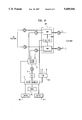
- FIG. 8 is a block diagram describing the functions of the invention.
- bay 100 comprising left frame 11 and right frame 13 which support upper bracket 12 which extends across the interior of the bay.
- Each frame defines a series of mounting holes approximately one inch on center.
- Top support bracket 14 is attached to upper bracket 12, extending to the rear of the bay to meet rear bracket 15.
- Upper duct walls 20 and lower duct walls 21 are supported by frames 11 and 13 on the left and right sides of the bay, respectively.
- Rear bracket 15 is also attached to the upper duct walls to strengthen them.
- the frames also support a multiplicity of rear support bracket assemblies 23 each having a shoulder stud 24 which is adapted to hold a shelf (not yet shown) in place while it is attached to the bay. This feature aids craftpersons in the quick assembly and removal of shelves in the bay.
- Lower raceway 26 is adapted to restrain fiber optic cables and it is supported by left frame 11 and right frame 13.
- the attachment is made by fastening means 27, many forms of which are well known in the art, such as screws, rivets, push-on clips, and the like. Similar means are used throughout the assembly of the operations center.
- FIG. 2 there is shown rear bottom frame 30, secured by fastening means 31, to lower duct walls 21.
- Service bracket 32 is fastened to left frame 11 and right frame 13 (not shown).
- the service bracket supports AC outlet assembly 35 which is adapted to supply power to the bay, and connector enclosure assembly 37 which is adapted to provide access to the bay for input and output electrical signals from other bays in the central office or from remote sites, such as manholes or customer's premises.
- upper raceway 40 having a radius 41.
- the raceway is adapted to restrain fiber optic cables and radius 41 ensures that they are protected from excessive bending stress and loss of their optical conductivity by providing a lower limiting radius about which they can be bent as they hang down from the raceway.
- a series of support shelves 44 each having a mounting bracket 45 attached thereto, are shown in a partially extended position in the bay. Roll-out shelves for electronic equipment are well known and commercially available. Monitor housing 42 is shown fastened to one of these shelves.
- a multiplicity of stiffeners 47 which provide rigidity to the bay, are shown attached to frame 13.
- facial rails 50 on the left and right sides of the bay, each being attached to frames 11 and 13, respectively.
- Each facial rail defines a series of holes 51.
- the facial rails are U-shaped sections and at least one side of the U defines a series of square holes which are spaced approximately one inch on centers.
- facial panel 60 which has an inner surface 61 upon which are mounted latches 64 on the left and right sides of the inner surface.
- the facial panel is pivotally attached to side brackets 62 on the left and right sides of the facial panel.
- Each side bracket supports at least one fastener 66 which is adapted to penetrate any of holes 51 to secure the side bracket to facial rail 50.
- fastener 66 is supplied by Hartwell Corp. of Placentia, Calif.
- Nylatch® under the tradename, Nylatch®.
- An advantage of the Nylatch fastener is that it is secured against the facial rail by a quarter-turn rotation.
- the spacing of holes 51 say at approximately one inch on centers, has the advantage of flexibility in mounting various sized components on shelves 44.
- Facial panels 60 cover these components and are typically five, seven, or nine inches high, having louvers 69 to provide air flow to heat-generating components.
- a smart LGX® operations center comprising optical switch 73, remote test unit 74, monitor 75, writing shelf 76, keyboard 77, system controller 78, node shelf 79, and printer shelf 80 in addition to the elements previously described.
- Fuse panel 61 is located high in the bay for easy visibility and located in front for easy access for replacement. It is supported by upper housing 40, which is located on top of the bay to accept incoming/outgoing fiber optic cables.
- the optical switch is located below the upper raceway and serves to switch all the functions of the operations center into any of the fiber optic cables connected to the bay.
- Remote test unit 74 supplies a signal of at least one wavelength to a selected fiber optic cable and is adapted to receive reflections from that signal from any physical discontinuities or breaks in the cable. It can determine the amplitude of the reflected signals and the distance of any discontinuity from the test unit.
- the remote test unit is an optical time domain reflectometer, the operation of which is well known in the art.
- a pair of cable radius 62 is shown between the optical switch and the remote test unit. Each provides the same function as the radius in the upper raceway, namely, to prevent damage and unnecessary optical signal loss to the cables. Additional cable radius 62 may be positioned as needed throughout the bay.
- monitor 75 is at approximately eye level to a craftperson, and it is one output means provided by the operations center to alert the craftperson about conditions in the cable network.
- Other output means may include a rack mounted alphanumeric display, an audible alarm, a printer, a beeper, and a line linking the system controller to a remote site such as a manhole via connector enclosure assembly 37 described in FIG. 2.
- Writing shelf 76 is conveniently placed below the monitor to support notepads and network operations manuals.
- Keyboard 77 is an input means to direct system controller 78 located below it.
- Other input means may be a mouse or a line connected to a hand held unit operated by a craftperson in a remote manhole. This line is connected to the system controller via connector enclosure assembly 37.
- the system controller is a computer that operates with algorithms specifically developed for the surveillance, testing, monitoring, or alarm signaling of a fiber optic network.
- Node shelf 79 contains additional electronic/optical modules to interconnect the signals from the remote test unit to a selected cable.
- the printer shelf is provided to hold a printer which provides hard copies of data from the system controller.
- FIG. 7 shows the fiber optic operations center with facial panels 60, held in a closed position by latches 64, which are louvered in positions where they cover heat-generating equipment like a remote test unit or system controller.
- FIG. 7 shows one advantageous embodiment illustrating how the operations center in normal use in a central office, however, it will be understood that because of the modular nature of the center, components thereof may be arranged to produce any number of combinations.
- a set of transmit receive fiber optic cables connected to customers is shown entering module 817.
- a multiplicity of n fiber optic cables, each having a transmit and receive fiber connect to a multiplicity of modules.
- the cables may be single mode or multimode, and they carry information using at least one wavelength.
- the optical switch 73 may have multiple stages and it selects one of the customer cables under the direction of system controller 78 receiving its optical input from the RTU.
- the optical switch connects transmit and receive fibers, T i and T r , respectively, to the RTU 74 which contains both optical and electronic circuits to generate and sample test signals.
- the (WDM) multiplexers 803 mix optical test signals from the RTU 74, which is an optical time domain reflectometer in a preferred embodiment with customer service signals.
- the optical time domain reflectometer is adapted to send optical pulses of at least one wavelength into a fiber optic cable, monitor reflected portions of that pulse, convert that information into an electronic signal, and feed that electronic signal to the system controller.
- the system controller is also connected to input means 809, a source of algorithms 811, and output means 813.
- the input means may be: a keyboard, a mouse, or a line to a remote site, used alone or in combination.
- the source of algorithms is a memory which contains instructions and reference data relating to the performance of the fiber optic network.
- the output means may be: a visual rack mounted alphanumeric display, an audible alarm, a monitor, a printer, a signal to activate a beeper carried by a craftperson, or a line to a remote site such as a manhole, used alone or in combination.
- the operations center may operate under manual control for fault detection or it may operate under the direction of the algorithms to sequentially sample the n customer lines and compare their characteristics to standard values.
- the operations center is also connected to LAN 815, a local area network within the fiber optic cable network served by the central office.
- Inputs to the LAN are from a multiplicity of m modules 817, distributed throughout the network, each containing a sensor which is adapted to monitor optical performance in a fiber optic cable and to provide a sensor alarm when a preset signal or performance threshold is violated.
- system controller 78 receives this information it initiates further sampling of the fiber by the remote test unit.
- the operations center thus provides continuous monitoring of the network via distributed sensors which detect the integrity of traffic-bearing or non-traffic-bearing fiber optic cables.
- the advantages of the operations center are its compatibility with the embedded base of hardware which has already been installed in central offices since it can be placed under the upper raceway among distribution frames.
- the operations center provides continuous monitoring of fiber optic cable integrity. It also improves the functionality of these offices by organizing fiber troughs within the bay, providing an easily visible and accessible fuse module, having removable facial panels, and providing a logical arrangement of equipment in modular units with standard sizes.
- Another advantage of the operations center is the incorporation of human factors design considerations by organizing test, control, and input/output means in a logical fashion in a single, self-contained bay.
Abstract
Description
Claims (20)
Priority Applications (4)
| Application Number | Priority Date | Filing Date | Title |
|---|---|---|---|
| US08/709,978 US5689604A (en) | 1996-09-09 | 1996-09-09 | Fiber optic operations center |
| CA002211816A CA2211816C (en) | 1996-09-09 | 1997-07-30 | Fiber optic operations center |
| EP97306783A EP0828395A2 (en) | 1996-09-09 | 1997-09-02 | Fiber optic operations center |
| JP9241034A JPH10135907A (en) | 1996-09-09 | 1997-09-05 | Optical fiber operation center |
Applications Claiming Priority (1)
| Application Number | Priority Date | Filing Date | Title |
|---|---|---|---|
| US08/709,978 US5689604A (en) | 1996-09-09 | 1996-09-09 | Fiber optic operations center |
Publications (1)
| Publication Number | Publication Date |
|---|---|
| US5689604A true US5689604A (en) | 1997-11-18 |
Family
ID=24852111
Family Applications (1)
| Application Number | Title | Priority Date | Filing Date |
|---|---|---|---|
| US08/709,978 Expired - Fee Related US5689604A (en) | 1996-09-09 | 1996-09-09 | Fiber optic operations center |
Country Status (4)
| Country | Link |
|---|---|
| US (1) | US5689604A (en) |
| EP (1) | EP0828395A2 (en) |
| JP (1) | JPH10135907A (en) |
| CA (1) | CA2211816C (en) |
Cited By (40)
| Publication number | Priority date | Publication date | Assignee | Title |
|---|---|---|---|---|
| US5915061A (en) * | 1996-04-05 | 1999-06-22 | Pirelli Cavi S.P.A. | Apparatus and method for housing optical components |
| US5960130A (en) * | 1997-09-22 | 1999-09-28 | Lucent Technologies Inc. | Method of testing splice connections in an optical fiber cable |
| US6222975B1 (en) * | 1998-12-11 | 2001-04-24 | Lucent Technologies, Inc. | System and method for detecting and reporting the use of optical fibers in fiber optic cables |
| US6269000B1 (en) * | 1997-07-09 | 2001-07-31 | Husky Injection Molding Systems, Ltd. | Power electrical enclosure |
| WO2002016991A1 (en) * | 2000-08-23 | 2002-02-28 | Ccs Technology, Inc. | Arrangement for the coupling of a number of first light waveguide fibres with a number of second light waveguide fibres |
| US6356698B1 (en) * | 1999-12-14 | 2002-03-12 | Tycom (Us) Inc. | Optical tray cover |
| US6360049B1 (en) * | 2000-02-01 | 2002-03-19 | Lucent Technologies, Inc. | Method for managing fiber and copper cable in distributing frame or bay shelves |
| US6362422B1 (en) | 2000-06-02 | 2002-03-26 | Michael T. Vavrik | Enclosure for use in fiber optic management systems |
| US6400883B1 (en) * | 2000-09-29 | 2002-06-04 | Lucent Technologies Inc. | Fiber distribution frame with integral active electrical panel |
| US20020101630A1 (en) * | 2001-02-01 | 2002-08-01 | Adc Telecommunications, Inc. | Monitor, control and configuration of fiber node via cable modem |
| US6437894B1 (en) * | 1998-12-11 | 2002-08-20 | Fitel Usa Corp. | Fiber distribution shelf assembly for a fiber administration system having integral line tracing capabilities |
| US6477486B1 (en) * | 1998-09-10 | 2002-11-05 | Dell Usa, L.P. | Automatic location determination of devices under test |
| US6501899B1 (en) | 2000-06-02 | 2002-12-31 | Panduit Corp. | Vertical cable management system |
| US6535682B1 (en) | 1999-03-01 | 2003-03-18 | Adc Telecommunications, Inc. | Optical fiber distribution frame with connector modules |
| US6556763B1 (en) | 1999-03-01 | 2003-04-29 | Adc Telecommunications, Inc. | Optical fiber distribution frame with connector modules |
| US6584267B1 (en) | 2000-06-02 | 2003-06-24 | Panduit Corp. | Cable management system |
| US6586680B1 (en) | 2000-06-02 | 2003-07-01 | Panduit Corp. | Modular bend radius control fixture |
| US6614978B1 (en) | 2000-06-02 | 2003-09-02 | Panduit Corp. | Slack cable management system |
| US20030202767A1 (en) * | 1998-09-10 | 2003-10-30 | Glynn Thomas A. | Telecommunications fiber optic infrastructure |
| US6647197B1 (en) | 2000-06-02 | 2003-11-11 | Panduit Corp. | Modular latch and guide rail arrangement for use in fiber optic cable management systems |
| US6760531B1 (en) | 1999-03-01 | 2004-07-06 | Adc Telecommunications, Inc. | Optical fiber distribution frame with outside plant enclosure |
| US20050084200A1 (en) * | 2003-10-16 | 2005-04-21 | 3M Innovative Properties Company | Multi-layer optical circuit and method for making |
| US20060029353A1 (en) * | 2004-08-09 | 2006-02-09 | Bolster Kristofer J | Modules including multiple rows of adapters for high density optical fiber distribution frame |
| US20060062538A1 (en) * | 2004-09-17 | 2006-03-23 | Fujitsu Limited | Structured shelf |
| US20060193591A1 (en) * | 2003-12-23 | 2006-08-31 | Adc Telecommunications, Inc. | High density optical fiber distribution frame with modules |
| US8417074B2 (en) | 2008-11-21 | 2013-04-09 | Adc Telecommunications, Inc. | Fiber optic telecommunications module |
| USRE44758E1 (en) | 2003-03-20 | 2014-02-11 | Adc Telecommunications, Inc. | Optical fiber interconnect cabinets, termination modules and fiber connectivity management for the same |
| US20140161410A1 (en) * | 2012-12-11 | 2014-06-12 | Tyco Electronics Raychem Bvba | Universal cable management system for telecommunications rack |
| US8770861B2 (en) | 2011-09-27 | 2014-07-08 | Tyco Electronics Corporation | Outside plant termination enclosure |
| US8958679B2 (en) | 2010-03-02 | 2015-02-17 | Tyco Electronics Services Gmbh | Fibre-optic telecommunications module |
| US9146374B2 (en) | 2012-09-28 | 2015-09-29 | Adc Telecommunications, Inc. | Rapid deployment packaging for optical fiber |
| US9223094B2 (en) | 2012-10-05 | 2015-12-29 | Tyco Electronics Nederland Bv | Flexible optical circuit, cassettes, and methods |
| US9435975B2 (en) | 2013-03-15 | 2016-09-06 | Commscope Technologies Llc | Modular high density telecommunications frame and chassis system |
| US9494758B2 (en) | 2014-04-03 | 2016-11-15 | Commscope Technologies Llc | Fiber optic distribution system |
| US9535229B2 (en) | 2011-10-07 | 2017-01-03 | Commscope Technologies Llc | Fiber optic cassette, system, and method |
| US9851524B2 (en) | 2014-01-28 | 2017-12-26 | Commscope Technologies Llc | Slidable fiber optic connection module with cable slack management |
| US11372165B2 (en) | 2011-09-12 | 2022-06-28 | Commscope Technologies Llc | Flexible lensed optical interconnect device for signal distribution |
| US11409068B2 (en) | 2017-10-02 | 2022-08-09 | Commscope Technologies Llc | Fiber optic circuit and preparation method |
| US11592628B2 (en) | 2012-09-28 | 2023-02-28 | Commscope Technologies Llc | Fiber optic cassette |
| CN116859535A (en) * | 2023-07-06 | 2023-10-10 | 杭州恒固科技有限公司 | Optical fiber distribution frame and remote network management system thereof |
Families Citing this family (4)
| Publication number | Priority date | Publication date | Assignee | Title |
|---|---|---|---|---|
| US5956439A (en) * | 1997-09-22 | 1999-09-21 | Lucent Technologies Inc. | Optical switching apparatus for use in the construction mode testing of fibers in an optical cable |
| CN101860398B (en) | 2006-02-03 | 2013-02-20 | 株式会社藤仓 | Light beam path monitoring device and light beam path monitoring method |
| CN104749518B (en) * | 2014-12-18 | 2017-09-29 | 吉林大学 | A kind of linearity measure device and method of waveguide electro-optic switch arrays |
| WO2021232351A1 (en) * | 2020-05-21 | 2021-11-25 | 南京溧水高新创业投资管理有限公司 | Distribution frame for information technology engineering |
Citations (8)
| Publication number | Priority date | Publication date | Assignee | Title |
|---|---|---|---|---|
| US5204925A (en) * | 1991-09-11 | 1993-04-20 | At&T Bell Laboratories | Optical interconnection of circuit packs |
| US5339379A (en) * | 1993-06-18 | 1994-08-16 | Telect, Inc. | Telecommunication fiber optic cable distribution apparatus |
| US5402515A (en) * | 1994-03-01 | 1995-03-28 | Minnesota Mining And Manufacturing Company | Fiber distribution frame system, cabinets, trays and fiber optic connector couplings |
| US5448675A (en) * | 1994-06-09 | 1995-09-05 | At&T Ipm Corp. | Telecommunications distribution frame with tracing |
| US5461693A (en) * | 1994-07-14 | 1995-10-24 | At&T Ipm Corp. | Optical fiber distribution frame with fiber testing |
| US5511144A (en) * | 1994-06-13 | 1996-04-23 | Siecor Corporation | Optical distribution frame |
| US5513293A (en) * | 1994-11-29 | 1996-04-30 | At&T Corp. | Optical backplane for a telecommunication distribution frame |
| US5530954A (en) * | 1995-01-13 | 1996-06-25 | Telect, Inc. | Telecommunication fiber optic patch panel shelf assembly |
-
1996
- 1996-09-09 US US08/709,978 patent/US5689604A/en not_active Expired - Fee Related
-
1997
- 1997-07-30 CA CA002211816A patent/CA2211816C/en not_active Expired - Fee Related
- 1997-09-02 EP EP97306783A patent/EP0828395A2/en not_active Withdrawn
- 1997-09-05 JP JP9241034A patent/JPH10135907A/en active Pending
Patent Citations (8)
| Publication number | Priority date | Publication date | Assignee | Title |
|---|---|---|---|---|
| US5204925A (en) * | 1991-09-11 | 1993-04-20 | At&T Bell Laboratories | Optical interconnection of circuit packs |
| US5339379A (en) * | 1993-06-18 | 1994-08-16 | Telect, Inc. | Telecommunication fiber optic cable distribution apparatus |
| US5402515A (en) * | 1994-03-01 | 1995-03-28 | Minnesota Mining And Manufacturing Company | Fiber distribution frame system, cabinets, trays and fiber optic connector couplings |
| US5448675A (en) * | 1994-06-09 | 1995-09-05 | At&T Ipm Corp. | Telecommunications distribution frame with tracing |
| US5511144A (en) * | 1994-06-13 | 1996-04-23 | Siecor Corporation | Optical distribution frame |
| US5461693A (en) * | 1994-07-14 | 1995-10-24 | At&T Ipm Corp. | Optical fiber distribution frame with fiber testing |
| US5513293A (en) * | 1994-11-29 | 1996-04-30 | At&T Corp. | Optical backplane for a telecommunication distribution frame |
| US5530954A (en) * | 1995-01-13 | 1996-06-25 | Telect, Inc. | Telecommunication fiber optic patch panel shelf assembly |
Cited By (94)
| Publication number | Priority date | Publication date | Assignee | Title |
|---|---|---|---|---|
| AU716127B2 (en) * | 1996-04-05 | 2000-02-17 | Corning O.T.I Inc. | Apparatus and method for housing optical components |
| US5915061A (en) * | 1996-04-05 | 1999-06-22 | Pirelli Cavi S.P.A. | Apparatus and method for housing optical components |
| US6269000B1 (en) * | 1997-07-09 | 2001-07-31 | Husky Injection Molding Systems, Ltd. | Power electrical enclosure |
| US5960130A (en) * | 1997-09-22 | 1999-09-28 | Lucent Technologies Inc. | Method of testing splice connections in an optical fiber cable |
| US6728460B2 (en) | 1998-09-10 | 2004-04-27 | Thomas A. Glynn | Telecommunications fiber optic infrastructure |
| US6721482B1 (en) * | 1998-09-10 | 2004-04-13 | Thomas A. Glynn | Telecommunications fiber optic infrastructure |
| US6692162B2 (en) | 1998-09-10 | 2004-02-17 | Thomas A. Glynn | Telecommunications fiber optic infrastructure |
| US20030202767A1 (en) * | 1998-09-10 | 2003-10-30 | Glynn Thomas A. | Telecommunications fiber optic infrastructure |
| US6477486B1 (en) * | 1998-09-10 | 2002-11-05 | Dell Usa, L.P. | Automatic location determination of devices under test |
| US6437894B1 (en) * | 1998-12-11 | 2002-08-20 | Fitel Usa Corp. | Fiber distribution shelf assembly for a fiber administration system having integral line tracing capabilities |
| US6222975B1 (en) * | 1998-12-11 | 2001-04-24 | Lucent Technologies, Inc. | System and method for detecting and reporting the use of optical fibers in fiber optic cables |
| US6535682B1 (en) | 1999-03-01 | 2003-03-18 | Adc Telecommunications, Inc. | Optical fiber distribution frame with connector modules |
| US20090022467A1 (en) * | 1999-03-01 | 2009-01-22 | Adc Telecommunications, Inc. | Optical fiber distribution frame with outside plant enclosure |
| US7139461B2 (en) | 1999-03-01 | 2006-11-21 | Adc Telecommunications, Inc. | Optical fiber distribution frame with outside plant enclosure |
| US10067309B2 (en) | 1999-03-01 | 2018-09-04 | Commscope Technologies Llc | Optical fiber distribution frame with outside plant enclosure |
| US6556763B1 (en) | 1999-03-01 | 2003-04-29 | Adc Telecommunications, Inc. | Optical fiber distribution frame with connector modules |
| US8768134B2 (en) | 1999-03-01 | 2014-07-01 | Adc Telecommunications, Inc. | Optical fiber distribution frame with outside plant enclosure |
| US20060193590A1 (en) * | 1999-03-01 | 2006-08-31 | Adc Telecommunications, Inc. | Optical fiber distribution frame with outside plant enclosure |
| US9429728B2 (en) | 1999-03-01 | 2016-08-30 | Commscope Technologies Llc | Optical fiber distribution frame with outside plant enclosure |
| US7149398B2 (en) | 1999-03-01 | 2006-12-12 | Adc Telecommunications, Inc. | Optical fiber distribution frame with outside plant enclosure |
| US7805043B2 (en) | 1999-03-01 | 2010-09-28 | Adc Telecommunications, Inc. | Optical fiber distribution frame with outside plant enclosure |
| US7333707B2 (en) | 1999-03-01 | 2008-02-19 | Adc Telecommunications, Inc. | Optical fiber distribution frame with outside plant enclosure |
| US8019192B2 (en) | 1999-03-01 | 2011-09-13 | Adc Telecommunications, Inc. | Optical fiber distribution frame with outside plant enclosure |
| US20050100301A1 (en) * | 1999-03-01 | 2005-05-12 | Adc Telecommunications, Inc. | Optical fiber distribution frame with outside plant enclosure |
| US6760531B1 (en) | 1999-03-01 | 2004-07-06 | Adc Telecommunications, Inc. | Optical fiber distribution frame with outside plant enclosure |
| US20040146266A1 (en) * | 1999-03-01 | 2004-07-29 | Solheid James J. | Optical fiber distribution frame with outside plant enclosure |
| US9810868B2 (en) | 1999-03-01 | 2017-11-07 | Commscope Technologies Llc | Optical fiber distribution frame with outside plant enclosure |
| US6356698B1 (en) * | 1999-12-14 | 2002-03-12 | Tycom (Us) Inc. | Optical tray cover |
| US6360049B1 (en) * | 2000-02-01 | 2002-03-19 | Lucent Technologies, Inc. | Method for managing fiber and copper cable in distributing frame or bay shelves |
| US6614978B1 (en) | 2000-06-02 | 2003-09-02 | Panduit Corp. | Slack cable management system |
| US6647197B1 (en) | 2000-06-02 | 2003-11-11 | Panduit Corp. | Modular latch and guide rail arrangement for use in fiber optic cable management systems |
| US6586680B1 (en) | 2000-06-02 | 2003-07-01 | Panduit Corp. | Modular bend radius control fixture |
| US6584267B1 (en) | 2000-06-02 | 2003-06-24 | Panduit Corp. | Cable management system |
| US6501899B1 (en) | 2000-06-02 | 2002-12-31 | Panduit Corp. | Vertical cable management system |
| US6362422B1 (en) | 2000-06-02 | 2002-03-26 | Michael T. Vavrik | Enclosure for use in fiber optic management systems |
| WO2002016991A1 (en) * | 2000-08-23 | 2002-02-28 | Ccs Technology, Inc. | Arrangement for the coupling of a number of first light waveguide fibres with a number of second light waveguide fibres |
| US6400883B1 (en) * | 2000-09-29 | 2002-06-04 | Lucent Technologies Inc. | Fiber distribution frame with integral active electrical panel |
| US20020101630A1 (en) * | 2001-02-01 | 2002-08-01 | Adc Telecommunications, Inc. | Monitor, control and configuration of fiber node via cable modem |
| USRE46945E1 (en) | 2003-03-20 | 2018-07-10 | Commscope Technologies Llc | Optical fiber interconnect cabinets, termination modules and fiber connectivity management for the same |
| USRE44758E1 (en) | 2003-03-20 | 2014-02-11 | Adc Telecommunications, Inc. | Optical fiber interconnect cabinets, termination modules and fiber connectivity management for the same |
| USRE48675E1 (en) | 2003-03-20 | 2021-08-10 | Commscope Technologies Llc | Optical fiber interconnect cabinets, termination modules and fiber connectivity management for the same |
| US7130498B2 (en) | 2003-10-16 | 2006-10-31 | 3M Innovative Properties Company | Multi-layer optical circuit and method for making |
| US20050084200A1 (en) * | 2003-10-16 | 2005-04-21 | 3M Innovative Properties Company | Multi-layer optical circuit and method for making |
| US7983521B2 (en) | 2003-12-23 | 2011-07-19 | Adc Telecommunications, Inc. | Fiber optic termination system with retention mechanism |
| US8358900B2 (en) | 2003-12-23 | 2013-01-22 | Adc Telecommunications, Inc. | Fiber optic module with adapters mounted at open front |
| US7822313B2 (en) | 2003-12-23 | 2010-10-26 | Adc Telecommunications, Inc. | Fiber optic termination system with retention mechanism |
| US20110038591A1 (en) * | 2003-12-23 | 2011-02-17 | Adc Telecommunications, Inc. | Fiber optic termination system with retention mechanism |
| US20100003000A1 (en) * | 2003-12-23 | 2010-01-07 | Adc Telecommunications, Inc. | Fiber optic termination system with retention mechanism |
| US7555193B2 (en) | 2003-12-23 | 2009-06-30 | Adc Telecommunications, Inc. | Fiber optic termination module with retention mechanism |
| US7367823B2 (en) | 2003-12-23 | 2008-05-06 | Adc Telecommunications, Inc. | Fiber optic module |
| US20080219634A1 (en) * | 2003-12-23 | 2008-09-11 | Adc Telecommunications, Inc. | High density optical fiber distribution frame with modules |
| US20060193591A1 (en) * | 2003-12-23 | 2006-08-31 | Adc Telecommunications, Inc. | High density optical fiber distribution frame with modules |
| US7376321B2 (en) | 2004-08-09 | 2008-05-20 | Adc Telecommunications, Inc. | Modules including multiple rows of adapters for high density optical fiber distribution frame |
| US8139913B2 (en) | 2004-08-09 | 2012-03-20 | Adc Telecommunications, Inc. | Modules including multiple rows of adapters for high density optical fiber distribution frame |
| US20100322577A1 (en) * | 2004-08-09 | 2010-12-23 | Adc Telecommunications, Inc. | Modules including multiple rows of adapters for high density optical fiber distribution frame |
| US20060029353A1 (en) * | 2004-08-09 | 2006-02-09 | Bolster Kristofer J | Modules including multiple rows of adapters for high density optical fiber distribution frame |
| US7522804B2 (en) * | 2004-09-17 | 2009-04-21 | Fujitsu Limited | Structured shelf |
| US20060062538A1 (en) * | 2004-09-17 | 2006-03-23 | Fujitsu Limited | Structured shelf |
| US8417074B2 (en) | 2008-11-21 | 2013-04-09 | Adc Telecommunications, Inc. | Fiber optic telecommunications module |
| US8958679B2 (en) | 2010-03-02 | 2015-02-17 | Tyco Electronics Services Gmbh | Fibre-optic telecommunications module |
| US11372165B2 (en) | 2011-09-12 | 2022-06-28 | Commscope Technologies Llc | Flexible lensed optical interconnect device for signal distribution |
| US8770861B2 (en) | 2011-09-27 | 2014-07-08 | Tyco Electronics Corporation | Outside plant termination enclosure |
| US11561356B2 (en) | 2011-10-07 | 2023-01-24 | Commscope Technologies Llc | Fiber optic cassette, system, and method |
| US11061197B2 (en) | 2011-10-07 | 2021-07-13 | Commscope Technologies Llc | Fiber optic cassette, system, and method |
| US9535229B2 (en) | 2011-10-07 | 2017-01-03 | Commscope Technologies Llc | Fiber optic cassette, system, and method |
| US9952400B2 (en) | 2011-10-07 | 2018-04-24 | Commscope Technologies Llc | Fiber optic cassette, system, and method |
| US10578821B2 (en) | 2011-10-07 | 2020-03-03 | Commscope Technologies Llc | Fiber optic cassette, system, and method |
| US9470869B2 (en) | 2012-09-28 | 2016-10-18 | Commscope Technologies Llc | Rapid deployment packaging for optical fiber |
| US9146374B2 (en) | 2012-09-28 | 2015-09-29 | Adc Telecommunications, Inc. | Rapid deployment packaging for optical fiber |
| US11592628B2 (en) | 2012-09-28 | 2023-02-28 | Commscope Technologies Llc | Fiber optic cassette |
| US9927591B2 (en) | 2012-09-28 | 2018-03-27 | Commscope Technologies Llc | Rapid deployment packaging for optical fiber |
| US10955633B2 (en) | 2012-10-05 | 2021-03-23 | Commscope Asia Holdings B.V. | Flexible optical circuit, cassettes, and methods |
| US9874711B2 (en) | 2012-10-05 | 2018-01-23 | Commscope Asia Holdings B.V. | Flexible optical circuit, cassettes, and methods |
| US11573389B2 (en) | 2012-10-05 | 2023-02-07 | Commscope Asia Holdings B.V. | Flexible optical circuit, cassettes, and methods |
| US10317638B2 (en) | 2012-10-05 | 2019-06-11 | Commscope Asia Holdings B.V. | Flexible optical circuit, cassettes, and methods |
| US9223094B2 (en) | 2012-10-05 | 2015-12-29 | Tyco Electronics Nederland Bv | Flexible optical circuit, cassettes, and methods |
| US9817202B2 (en) * | 2012-12-11 | 2017-11-14 | CommScope Connectivity Belgium BVBA | Universal cable management system for telecommunications rack |
| US20140161410A1 (en) * | 2012-12-11 | 2014-06-12 | Tyco Electronics Raychem Bvba | Universal cable management system for telecommunications rack |
| US9348104B2 (en) * | 2012-12-11 | 2016-05-24 | CommScope Connectivity Belgium BVBA | Universal cable management system for telecommunications rack |
| US20170023760A1 (en) * | 2012-12-11 | 2017-01-26 | CommScope Connectivity Belgium BVBA | Universal cable management system for telecommunications rack |
| US10473875B2 (en) | 2013-03-15 | 2019-11-12 | Commscope Technologies Llc | Modular high density telecommunications frame and chassis system |
| US9435975B2 (en) | 2013-03-15 | 2016-09-06 | Commscope Technologies Llc | Modular high density telecommunications frame and chassis system |
| US9952398B2 (en) | 2013-03-15 | 2018-04-24 | Commscope Technologies Llc | Modular high density telecommunications frame and chassis system |
| US11249270B2 (en) | 2014-01-28 | 2022-02-15 | Commscope Technologies Llc | Slidable fiber optic connection module with cable slack management |
| US10545307B2 (en) | 2014-01-28 | 2020-01-28 | Commscope Technologies Llc | Slidable fiber optic connection module with cable slack management |
| US9851524B2 (en) | 2014-01-28 | 2017-12-26 | Commscope Technologies Llc | Slidable fiber optic connection module with cable slack management |
| US11733472B2 (en) | 2014-01-28 | 2023-08-22 | Commscope Technologies Llc | Slidable fiber optic connection module with cable slack management |
| US10481357B2 (en) | 2014-04-03 | 2019-11-19 | Commscope Technologies Llc | Fiber optic distribution system |
| US9494758B2 (en) | 2014-04-03 | 2016-11-15 | Commscope Technologies Llc | Fiber optic distribution system |
| US9977212B2 (en) | 2014-04-03 | 2018-05-22 | Commscope Technologies Llc | Fiber optic distribution system |
| US11409068B2 (en) | 2017-10-02 | 2022-08-09 | Commscope Technologies Llc | Fiber optic circuit and preparation method |
| US11609400B2 (en) | 2017-10-02 | 2023-03-21 | Commscope Technologies Llc | Fiber optic circuit and preparation method |
| CN116859535A (en) * | 2023-07-06 | 2023-10-10 | 杭州恒固科技有限公司 | Optical fiber distribution frame and remote network management system thereof |
| CN116859535B (en) * | 2023-07-06 | 2023-12-22 | 杭州恒固科技有限公司 | Optical fiber distribution frame and remote network management system thereof |
Also Published As
| Publication number | Publication date |
|---|---|
| EP0828395A2 (en) | 1998-03-11 |
| CA2211816C (en) | 2001-11-27 |
| CA2211816A1 (en) | 1998-03-09 |
| JPH10135907A (en) | 1998-05-22 |
Similar Documents
| Publication | Publication Date | Title |
|---|---|---|
| US5689604A (en) | Fiber optic operations center | |
| US6359565B1 (en) | Method and system for monitoring the thermal status of a card shelf | |
| EP0851257B1 (en) | Optical fiber connector housing | |
| EP0851255B1 (en) | Optical fiber distribution facility | |
| US6195493B1 (en) | Universal chassis for CATV headends or telecommunications company central office for optical electronic equipment | |
| US6330168B1 (en) | Card shelf cable management system and method | |
| SG97807A1 (en) | Troubleshooting computer systems during manufacturing using state and attribute information | |
| EP3509407B1 (en) | Rack pdu bracket with rotation function | |
| US5682301A (en) | Modular network cabling system for enterprise with multiple sites | |
| US20060032990A1 (en) | Rack and duct system | |
| US20060276164A1 (en) | Telecom equipment with memory | |
| Cisco | About this Guide | |
| Cisco | About This Manual | |
| Cisco | About This Manual | |
| Cisco | About This Manual | |
| Cisco | About This Manual | |
| Cisco | About This Manual | |
| Cisco | About This Manual | |
| Cisco | About This Manual | |
| Cisco | About This Manual | |
| Cisco | About This Manual | |
| Cisco | About This Book | |
| Cisco | About This Manual | |
| Cisco | About This Manual | |
| Cisco | About This Manual |
Legal Events
| Date | Code | Title | Description |
|---|---|---|---|
| AS | Assignment |
Owner name: LUCENT TECHNOLOGIES INC., NEW JERSEY Free format text: ASSIGNMENT OF ASSIGNORS INTEREST;ASSIGNORS:JANUS, NEAL ANTHONY;LEONE, FRANK SALVATORE;PARZYGNAT, WILLIAM JOSEPH;AND OTHERS;REEL/FRAME:008277/0241 Effective date: 19960906 |
|
| FEPP | Fee payment procedure |
Free format text: PAYOR NUMBER ASSIGNED (ORIGINAL EVENT CODE: ASPN); ENTITY STATUS OF PATENT OWNER: LARGE ENTITY |
|
| AS | Assignment |
Owner name: THE CHASE MANHATTAN BANK, AS COLLATERAL AGENT, TEX Free format text: CONDITIONAL ASSIGNMENT OF AND SECURITY INTEREST IN PATENT RIGHTS;ASSIGNOR:LUCENT TECHNOLOGIES INC. (DE CORPORATION);REEL/FRAME:011722/0048 Effective date: 20010222 |
|
| FPAY | Fee payment |
Year of fee payment: 4 |
|
| FPAY | Fee payment |
Year of fee payment: 8 |
|
| AS | Assignment |
Owner name: LUCENT TECHNOLOGIES INC., NEW JERSEY Free format text: TERMINATION AND RELEASE OF SECURITY INTEREST IN PATENT RIGHTS;ASSIGNOR:JPMORGAN CHASE BANK, N.A. (FORMERLY KNOWN AS THE CHASE MANHATTAN BANK), AS ADMINISTRATIVE AGENT;REEL/FRAME:018584/0446 Effective date: 20061130 |
|
| REMI | Maintenance fee reminder mailed | ||
| LAPS | Lapse for failure to pay maintenance fees | ||
| STCH | Information on status: patent discontinuation |
Free format text: PATENT EXPIRED DUE TO NONPAYMENT OF MAINTENANCE FEES UNDER 37 CFR 1.362 |
|
| FP | Lapsed due to failure to pay maintenance fee |
Effective date: 20091118 |