US5695102A - Elastic shoulder strap - Google Patents
Elastic shoulder strap Download PDFInfo
- Publication number
- US5695102A US5695102A US08/430,614 US43061495A US5695102A US 5695102 A US5695102 A US 5695102A US 43061495 A US43061495 A US 43061495A US 5695102 A US5695102 A US 5695102A
- Authority
- US
- United States
- Prior art keywords
- elastic
- carrying strap
- envelope
- connector
- outer envelope
- Prior art date
- Legal status (The legal status is an assumption and is not a legal conclusion. Google has not performed a legal analysis and makes no representation as to the accuracy of the status listed.)
- Expired - Lifetime
Links
Images


Classifications
-
- A—HUMAN NECESSITIES
- A45—HAND OR TRAVELLING ARTICLES
- A45F—TRAVELLING OR CAMP EQUIPMENT: SACKS OR PACKS CARRIED ON THE BODY
- A45F3/00—Travelling or camp articles; Sacks or packs carried on the body
- A45F3/02—Sacks or packs carried on the body by means of one strap passing over the shoulder
-
- A—HUMAN NECESSITIES
- A45—HAND OR TRAVELLING ARTICLES
- A45C—PURSES; LUGGAGE; HAND CARRIED BAGS
- A45C13/00—Details; Accessories
- A45C13/30—Straps; Bands
-
- A—HUMAN NECESSITIES
- A63—SPORTS; GAMES; AMUSEMENTS
- A63B—APPARATUS FOR PHYSICAL TRAINING, GYMNASTICS, SWIMMING, CLIMBING, OR FENCING; BALL GAMES; TRAINING EQUIPMENT
- A63B55/00—Bags for golf clubs; Stands for golf clubs for use on the course; Wheeled carriers specially adapted for golf bags
- A63B55/408—Releasably mounted accessories fitted outside the bag, e.g. straps or holders
-
- Y—GENERAL TAGGING OF NEW TECHNOLOGICAL DEVELOPMENTS; GENERAL TAGGING OF CROSS-SECTIONAL TECHNOLOGIES SPANNING OVER SEVERAL SECTIONS OF THE IPC; TECHNICAL SUBJECTS COVERED BY FORMER USPC CROSS-REFERENCE ART COLLECTIONS [XRACs] AND DIGESTS
- Y10—TECHNICAL SUBJECTS COVERED BY FORMER USPC
- Y10T—TECHNICAL SUBJECTS COVERED BY FORMER US CLASSIFICATION
- Y10T24/00—Buckles, buttons, clasps, etc.
- Y10T24/31—Plural fasteners having intermediate flaccid connector
- Y10T24/314—Elastic connector
- Y10T24/316—Strap connector
Definitions
- the present invention relates to an elastic load support centered above a composite central elastic portion that includes or is interconnected to load supporting straps.
- Coontz U.S. Pat. No. 4,976,388.
- a simple neoprene layer forms a cushion connected to the top exterior surface on an auxiliary strap. That strap is formed from two non-stretch portions and a center elastic piece which are stitched together. An elastic cover strap is then stitched in place over the auxiliary strap at spaced apart locations to provide an improved appearance and assists in improving mechanical function.
- the ends of the cover and non-stretch portions of the straps are bent in a U-shaped fashion about each end of the neoprene pad so that conventional snap fasteners can be provided at each end.
- neoprene pad which can include a nylon cover, as well as an auxiliary strap, with the neoprene pad and the auxiliary strap being connected together, again at spaced apart locations, by stitching.
- the strap can be a strong fabric in the form of a stronger elastic material. As with Coontz, the strap is fastened only to one exposed side of the neoprene pad.
- the resulting strap has either an irregularly shaped surface that is not suitable for printing and design purposes, or the exterior surface is covered with additional straps that can get in the way during use. Such exposed items can become twisted and do not provide a necessarily clean surface for aesthetic purposes.
- the resulting structures have only the stretch characteristics of each of the individual elements, there being no interrelationship between such elements that provides an improved or modified stretch nor is there a convenient way to fine tune stretch characteristics of the composite structure.
- the present invention solves these problems and relates to a composite elastic member and more specifically to the main central elastic member.
- a composite elastic member according to this invention that will be incorporated into a carrying strap, is formed in a way that produces a unitary shock absorbing structure which when finished, by appropriate choices of components, provides stretch characteristics and shock absorbing qualities that are tuneable for varying types of end uses and load carry situations.
- the attachment of individual components to one another yields a combined stretch and load absorbing capacity that is enhanced over that supplied by the individual elements.
- a strap according to this invention starts with the main elastic central portion. From that central portion two webbing portions, preferably comprised of a non-stretch material although certainly a strong stretch material could also be used, as well as an elastic central portion. These webbings can be formed integrally with the central portion or be removably connected to it by a variety of techniques.
- the central portion begins by forming an outer envelope from two layers of soft stretchable material, which may or may not be fabric covered.
- An internal elastic member is joined to this outer envelope thereby forming a composite structure.
- the elastic strip can extend from one end of the central portion to the other unit. It can extend between the two webbings or short pieces of such webbing material.
- the outer envelope also will preferably cover the connection between the elastic member and the two opposing end sections.
- the central portion is then finished by suitable edge binding material and separate end covers.
- connection between the internal elastic member and the outer envelope can be effected through a variety of techniques, as well as in a variety of areas. Included within such techniques would be a flexible and stretchable form of stitching, including use of elastic threads and sonic welding, as well as non-hardening flexible adhesives such as, for example, spray-on contact cements, mixed and spread silicone adhesives, or even injected resin foams, or combinations thereof. As to where such connection is placed, it is preferred that both sides of the elastic member be connected to the internal surfaces of the outer envelope. However, where elastic or stretchable strapping is used, the stitch can extend down portions of the outer envelope and inner elastic member interface. This would claim an appropriate connection to be made between the outer envelope and the elastic members yet permit the stretchable stitch portion to be decorative as well as the main connecting approach.
- connection approach it is preferred to have the internal surfaces of the outer envelope adhered to the inner elastic member, but it is also possible to make an excellent performing strap if only one side of the internal elastic member is adhesively bonded within and to that outer envelope.
- the webbing ends can be connected to one of a variety of connectors, either in the form of additional straps, snap fasteners, rotatable hooks or other conventional type connecting devices, so that either the central portion itself, or the whole strap, can be easily connected and disconnected from a load.
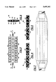
- FIG. 1 is a top plan view of the strap according to the present invention, a portion of which has been diagrammatically cut away to show the internal structure;
- FIG. 2 is a bottom plan view of the present invention
- FIG. 3 is a partially exploded side elevational view of the present invention.
- FIG. 4 is a diagrammatic partially exploded cross-sectional view of the central portion taken along cut line A--A of FIG. 1 and showing the use of a spray-on contact adhesive as the binding material;
- FIG. 5 is a cross-sectional view taken along line A--A of FIG. 1 and showing the use of polyurethane foam as the binding material;
- FIG. 6 is a cross-sectional view also along line A--A of FIG. 1 showing a cross-sectional view of a finished part of the central portion;
- FIG. 7 is a diagrammatic top plan view showing an additional embodiment of the present invention employing a plurality of elastic members within the central portion of the carrying strap.
- FIG. 8 shows the coefficient of structure for several straps.
- the shock absorbing and load bearing carrying strap is generally indicated at 10 and is comprised of two relatively non-elastic webbings 12 and 14 connected to a central portion, generally indicated at 16.
- Webbings 12 and 14 can be long and have outer ends 18 and 20 that are secured to one of a number of types of conventional connectors, or they can be provided with a releasable clip type structure, such as a conventional quick disconnect or side release type buckle, so that various types of connecting mechanisms can be employed.
- webbings 12 and 14 can be provided with loop connectors that would allow them to be lengthened or shortened depending upon the load being carried and the exact use to which the carrying strap is to be put.
- connectors include swivel snap hooks, D-rings, per loop connectors comprised of a quarter inch webbing, flip over and lockable straps.
- Webbings 12 and 14 could also be short enough so that each provides an internal connection with an internal elastic strip 26 but then extends only a short distance out of the ends of central portion 16. That distance need be only long enough to be connected to a conventional connector, including, for example, a D-ring or a quick release device.
- Webbings 12 and 14 also have opposite or interior ends 22 and 24, as shown in FIG. 3, that permit them to be respectively connected to an elastic strip 26, such as by stitching as indicated at 28, rivets or stitching or other permanent or fixed bond.
- Central portion 16 includes upper and lower stretchable pads 30 and 32, respectively, with the finished outer lateral edges being covered preferably with an elastic binding as at 34 and 36.
- the bottom or lower stretchable pad preferably the one that will ride against an individual's shoulder, neck or other area
- the bottom or lower stretchable pad can be provided with a plurality of rubberized or slip preventing features or indicia such as the dots, or other shapes, for example, can be stripes, open rings or squares or diamonds generally indicated at 38.
- These slip preventing features are preferably blends comprised of a plastisol or other rubberized-like compound that can be applied by silk screen printing techniques to provide resistance and prevent slippage.
- the stretchable pads 30, 32 can be provided also with an outer cover, as indicated at 40 and 42. Covers 40 and 42 can be sealed to the pads or otherwise bonded or formed therewith and will provide a convenient exterior surface for printing and for receiving the slip resistance elements 38.
- Pads 30 and 32 are preferably foam pads formed, for example, from neoprene or other stretchable foams or blends. However, other stretchable material, including stretch fabrics or layers of stretch material could be used. What is desired is to be able to build into the central portion desired amounts of elasticity to sufficiently control loads.
- Each of the ends of the central portion are preferably closed with a strap end closure, sometimes called a bag term end, separately indicated at 50 and 52, which are preferably stitched in place as indicated at 54. These end closures could also be held in place by adhesives.
- the outer cover 40 and 42 can be all forms of elastic, fabric or material, including that constructed of nylon, lycra, polyester, or combinations thereof, and the fabric can be either knit or woven. Further, additional materials such as leather and denim or other forms of more inelastic fabric can be used if shirred or bunched in a fashion that would permit the desired level of longitudinal expansion of the remaining internal elastic components.
- the upper and lower stretchable pads 30 and 32 are preferably comprised of 100% neoprene so that each will have good shape and elastic retention qualities.
- the pads 30 and 32 can be comprised of foam having the desired elasticity which can be rubber blends, EVA blends and neoprene blends, as well as polyfoams.
- the thickness of the top and bottom pads 30 and 32, respectively, can be either the same or can be varied, preferably with the lower pad 32 being thicker, with thicknesses of those pads varying from about 3/32 to about 1/2 inches, preferably from about 1/8 to about 3/8 inches.
- the elastic strip 26 can be comprised of a variety of elastic materials having varying co-efficients of elasticity.
- the central portion 16 can vary in its length from about 5 to about 25 inches and is preferably about 10 to 18 inches in overall length from one end of closure 50 to the opposite end of closure 52.
- Webbings 12 and 14 can have a length ranging from about 2 inches to 36 inches, with the preferred length preferably being about 14 to 24 inches, with a stretch length still permitting your attachment member to be provided at each end of central portion 16.
- the elastic strip 26 extends substantially along the full length of the central portion 16 so that for a 13 inch long central portion 16 the elastic strap 26 could be approximately 10 to 11 inches. In order to limit the stretch, a stiffer or heavier piece of elastic could be used, or alternatively the length could be shortened to be about five to seven inches to create the same or a similar effect.
- the stretchable pads 30 and 32 are each preferably bonded to both the elastic strip 26, on each side thereof, and to each other around their marginal edges beyond strip 16, such as indicated at 56, which is perhaps best seen in FIGS. 4 and 6.
- one adhesive alternative indicated at 60 is a contact cement such as, for example, 3M's high strength adhesive Spray 90, spray-on contact cement, Rubatex R27705 black neoprene contact adhesive material, or Bull's Eye Brand Contact Cement, Product Identification No. Bull's Eye No. 110 mist adhesives, Bull's Eye TABLELA low tack adhesive.
- contact cement Once contact cement is sprayed on the interior surfaces of pads 30 and 32, the contact cement will quickly become tacky so that those surfaces can be placed on the elastic strip 26 which has been previously connected, such as by stitching to webbings 12 and 14. When pressed down, pads 30 and 32 will adhere to the elastic strip 26 and will also adhere to each other along those lateral edges where they extend beyond elastic strip 26.
- edge binding 34 and 36 can be secured in place, with the binding preferably providing both a suitable way to dress the lateral edges of the layers forming the composite central portion 16.
- the binding can be the same as that used for the outer cover or skin of the pads 30 and 32, so that in addition to creating a finished edge, the binding can also provide some additional elasticity and stretch co-efficients of the central pad area can be improved thereby.
- Edge bindings 34 and 36 can be secured by stitching, a suitable adhesive or otherwise bonded to pads 30 and 32. Alternatively, the edges of the neoprene pads can simply be otherwise sealed, coated with a sealant or finishing material, or simply welded in place.
- the bag term ends 50 and 52 which have preferably been separately formed, either by injection molding if they are comprised of a rubber, a flexible resin compound, or other moldable material, or formed of leather or other decorative material or fabric can be fixed in place.
- These bag term ends can be slipped over the webbings 12 and 14 from each end, slid into place and then sewn into the position shown in FIG. 1 covering and protecting the ends of the neoprene pads in the central portion. It is preferred that the bag term ends be sewn, as at 54, so that sewing provides an additional connection between webbings 12 and 14 and the elastic strip 26, and also helps to firm up and strengthen each of the ends of the pads 30 and 32.
- the adhesive used to develop the composite structure of the central portion 16 can be a silicon adhesive, such as RTV manufactured by General Electric.
- This adhesive can be preferably either prepared as a two part mix and then spread onto the interior surfaces of pads 30 and 32.
- the RTV adhesive can alternatively be applied in the form of a stiffer mix in the form of an expressed caulk type material.
- the outer envelope is first partially assembled.
- the pads 30 and 32 can be placed on the elastic strip 26, the edges can be bound, such as by binding each of the lateral edges with bindings 34 and 36, and a bag term at one end can be fixed into place.
- This procedure will also provide a way of interconnecting the interior surfaces of the stretchable pads 30 and 32 to the elastic strip 26, as well as to portions of the webbing within the outer envelope defined by the stretchable pads 30 and 32, with all of those being adhered into an integral and operating composite unit.
- the same procedure could be used for initially assembling the outer envelope of the stretchable pads 30 and 32, including securing the lateral edge bindings 34 and 36 and by attaching one end closure, leaving the opposite end open.
- a resin foam such as, for example a polyurethane resin foam can be injected into the cavity formed by that outer envelope of the upper and lower stretchable pads 30 and 32.
- a polyurethane could be a two part mixture of Denflex RX-32018-A Black Base and Denflex 9951 prepolymer. As the foam develops it will move about the interior of that cavity within the outer pads as well as about the exterior surfaces of elastic strip 26 and when cured the foam will secure all the surfaces inside the outer envelope together.
- the opposite end closure would again be positioned and secured in place.
- the injected resin foam serves as an adhesive to bind the interior surfaces of the stretchable pads to the exterior surfaces of the elastic strip as well as the interior ends 22 and 24 of the webbing into an integral unit.
- the injected resin foam itself also becomes part of the integral composite elastic structure and will add its own additional stretch resistance characteristics thereby increasing the stretch co-efficient of the composite central portion 16 structure.
- connection approach used to provide a flexible, non-hardening joint between the individual components and the central portion 16, that permits the interconnected components to collectively stretch in parallel with each other can vary from elastic stitching, spray-on contact cements, silicon adhesives, and injected foam materials.
- the adhesives can also comprise other non-hardening flexible adhesives.
- the first relates to the percent stretch, which refers to the point where the elastic has been stretched to its limit and will not stretch any further.
- percent stretch refers to the point where the elastic has been stretched to its limit and will not stretch any further.
- a 10 inch piece of elastic formed from a 100% stretch material will reach its stretch limit when stretched, to a length of 20 inches.
- the desired range of percent stretch for the present invention will be less than 100% and preferably from 25% to 100%.
- the second variable is the co-efficient of stretch. This relates to the stretch per inch versus an applied force. Starting forces can vary from, for example, 1 to 50 pounds, with the preferred co-efficient of stretch varying from approximately 1.0 lbs/inch to about 4 lbs/inch. It has also been found that once the central portion is finished and constructed with all the components assembled and adhered together, the co-efficient of stretch for the composite structure is different from and greater than the simple sum of the components used to form that composite structure. For example, the graph in FIG. 8 shows the co-efficient of structure for several straps and allows a comparison between adhered and unadhered structures.
- A, B, C and D Four plots or sets of data points are labeled A, B, C and D.
- the plot identified by A relates to an unadhered composite structure while plot B is for the adhered structure.
- Each of these test members was formed using a 1.5 inch wide elastic strip manufactured by the John Howard Company, Inc., identified as a part number W5-580.
- This elastic strip is a woven product comprised of strands of rubber that are wrapped with a cotton thread. A ten inch long piece of this elastic strip was used so that after connection to the webbings 12 and 14, the effective stretchable length of the elastic strip was approximately 9.5 inches.
- the stretchable pads used to form the outer envelope included a 5/32 thick neoprene pad on one side and 1/8 thick neoprene pad on the opposite side.
- a spray-on contact cement Bull's Eye No. 110 Mist, was applied to the interior surfaces of the neoprene pads and the pads were pressed onto the elastic strip covering the joint between the elastic strip and the webbings. The lateral edges were bounded with a sewn on lycra binding.
- a piece of the John Howard elastic developed a co-efficient of stretch as depicted in graph A. A half inch stretch occurs at about 3.75 lbs of load and 4 inches of stretch is developed at about 8 lbs. However, a composite test member formed with the same John Howard elastic connected to the outer envelope pads by the spray on adhesive on all interior sides, is shown by graph B. An initial stretch of one half inch occurs about 5.5 lbs.
- the elastic stretch characteristics of the carrying strap vary from about 0.5 inches to a maximum of about 6 inches, with the preferred range being about 1 inch to 4 inches of total stretch for an effective 10 pound tension load for a load weight of 20 pounds. Even for heavier loads, up to about 50 pounds, it is still preferred to have the preferred range of stretch still continue to be between about 1 inch to about 4 inches. This would require heavier elastic member, use of injected foam or other higher co-efficient of stretch components. What is desired is to provide shock absorption and weight distribution to make the load more comfortable without having a rigid member nor one that was too elastic so that the load would bounce.
- the elastic strip in a modified central portion 16' can be in the form of a series or a plurality of individual elastic members 60.
- These can be solid elastic elements, bundled elastic bands, knit members or other stretchable cord-like members.
- This plurality of individual members can be connected together and then connected to webbings 12 and 14 or each can be separately connected directly to webbings 12 and 14. Thereafter, the outer pads forming the outer envelope can be attached to the elastic members 60 by one of the above identified approaches.
Abstract
Description
Claims (19)
Priority Applications (1)
| Application Number | Priority Date | Filing Date | Title |
|---|---|---|---|
| US08/430,614 US5695102A (en) | 1995-04-28 | 1995-04-28 | Elastic shoulder strap |
Applications Claiming Priority (1)
| Application Number | Priority Date | Filing Date | Title |
|---|---|---|---|
| US08/430,614 US5695102A (en) | 1995-04-28 | 1995-04-28 | Elastic shoulder strap |
Publications (1)
| Publication Number | Publication Date |
|---|---|
| US5695102A true US5695102A (en) | 1997-12-09 |
Family
ID=23708315
Family Applications (1)
| Application Number | Title | Priority Date | Filing Date |
|---|---|---|---|
| US08/430,614 Expired - Lifetime US5695102A (en) | 1995-04-28 | 1995-04-28 | Elastic shoulder strap |
Country Status (1)
| Country | Link |
|---|---|
| US (1) | US5695102A (en) |
Cited By (38)
| Publication number | Priority date | Publication date | Assignee | Title |
|---|---|---|---|---|
| US5915608A (en) * | 1998-06-01 | 1999-06-29 | Mao; Chen Shou | Shoulder strap buffering device of shoulder bag |
| FR2781135A1 (en) * | 1998-07-17 | 2000-01-21 | Rossignol Sa | Rucksack for skiers, motorcyclists, mountain climbers and snow boarders |
| FR2781349A1 (en) * | 1998-07-23 | 2000-01-28 | Janisset Sa | Shoulder strap shock absorber has travel limiter made as undulating piece molded over the whole length and either side of the strap and having transverse limiting bars |
| US6092574A (en) * | 1999-04-09 | 2000-07-25 | United States Luggage, L.P. | Carrying cases with strain relief shoulder attachments |
| US6601890B1 (en) * | 2000-11-28 | 2003-08-05 | Safe Shop Tools, Inc. | Cylinder lifting sling and method for making the same |
| US20050011520A1 (en) * | 2003-07-14 | 2005-01-20 | Rowe James A. | Medical tank strap system |
| US20050258205A1 (en) * | 2004-05-21 | 2005-11-24 | Michaels Of Oregon Co. | Shock-absorbing carrying strap |
| US20070155600A1 (en) * | 2002-10-09 | 2007-07-05 | Spri Products, Inc. | Exercise device |
| US20070261213A1 (en) * | 2006-05-10 | 2007-11-15 | Nolan Barara K | Detachable shock absorber accessory for shoulder strap |
| US20080265477A1 (en) * | 2007-04-26 | 2008-10-30 | Nike, Inc. | System For Moderating Forces |
| US20090090754A1 (en) * | 2007-10-06 | 2009-04-09 | Andreas Stihl Ag & Co. Kg. | Belt arrangement for carrying a portable handheld work apparatus |
| US20090294500A1 (en) * | 2008-05-30 | 2009-12-03 | Rooster Products International, Inc. | Load suspension system |
| WO2010099506A1 (en) * | 2009-02-26 | 2010-09-02 | Daymen Photo Marketing Lp | Self adjusting contoured strap device and method |
| US20100293759A1 (en) * | 2009-05-22 | 2010-11-25 | Stanley Hiroshi Wada | Shock absorbing apparatus for straps and ropes |
| USD628877S1 (en) | 2010-06-03 | 2010-12-14 | Master Lock Company Llc | Hook |
| USD629290S1 (en) | 2010-06-03 | 2010-12-21 | Master Lock Company Llc | Hook |
| US20100320243A1 (en) * | 2009-06-22 | 2010-12-23 | Tarek Hassan | Energy-absorbing shoulder strap system |
| USD633371S1 (en) | 2010-06-03 | 2011-03-01 | Master Lock Company Llc | Hook |
| WO2011061521A1 (en) * | 2009-11-17 | 2011-05-26 | Falcon Innovations (Northampton) Limited | Pad for shoulder strap |
| US20120012628A1 (en) * | 2010-03-30 | 2012-01-19 | Adidas Ag | Insert For A Carrying Strap |
| US20120037535A1 (en) * | 2010-08-10 | 2012-02-16 | Haller Clayton F | Stand-up pouch |
| US20120048900A1 (en) * | 2010-08-30 | 2012-03-01 | Benjamin Ben-Kai Wong | Anatomically adaptive and ergonomic load distribution strap |
| US8132699B2 (en) | 2006-12-19 | 2012-03-13 | Three Point Ventures Llc | Shoulder strap for bag |
| US20120061439A1 (en) * | 2010-09-14 | 2012-03-15 | Todd Wallis | Camera carrying apparatus, system, and method |
| US20120091294A1 (en) * | 2010-05-25 | 2012-04-19 | Cuadrado Xavier A | Universal heavy bag hanger |
| US20120261446A1 (en) * | 2011-04-13 | 2012-10-18 | Stegmeyer Alfred W | Shoulder strap and neck strap comprised of an oblong shaped pad and a strap |
| US20130221052A1 (en) * | 2010-11-12 | 2013-08-29 | Illinois Tool Works Inc. | Web load-dampening device |
| US8534515B2 (en) | 2011-08-04 | 2013-09-17 | M Group, Inc. | Pivoting elastic shoulder support |
| US8668127B2 (en) | 2011-02-28 | 2014-03-11 | Jake Ryan Baron | Stretchable backpack |
| US20140069975A1 (en) * | 2012-09-11 | 2014-03-13 | Thule Sweden Ab | Shock dampening protector for a bicycle wheel rim |
| US20160120333A1 (en) * | 2014-10-29 | 2016-05-05 | Theresa Brandner | Wearable child carriers and methods of use |
| WO2016120265A1 (en) * | 2015-01-26 | 2016-08-04 | Interspiro Ab | Harness and method for manufacturing thereof |
| USD772577S1 (en) | 2015-01-20 | 2016-11-29 | M Group, Inc. | Elastic shoulder support with shoulder pad and pivot |
| US9717321B2 (en) | 2014-11-07 | 2017-08-01 | Magpul Industries Corp. | Padded strap |
| US20170265631A1 (en) * | 2016-03-21 | 2017-09-21 | Peter Kao | Backpack with Suspension Arrangement |
| US20180303228A1 (en) * | 2017-04-22 | 2018-10-25 | Impax Marketing, LLC | Tool Support Strap |
| US10285480B2 (en) | 2016-06-27 | 2019-05-14 | Miko Chovich | Load conveyance system |
| WO2021116708A1 (en) * | 2019-12-12 | 2021-06-17 | Stretchline Intellectual Properties Limited | Stretchable textile article |
Citations (66)
| Publication number | Priority date | Publication date | Assignee | Title |
|---|---|---|---|---|
| DE19943C (en) * | R. BERGFELD und G. SEYDEL in Göppingen, Württemberg | Trouser belt | ||
| US518681A (en) * | 1894-04-24 | Radolpiius d | ||
| US860395A (en) * | 1907-04-27 | 1907-07-16 | Mills Woven Cartridge Belt Co | Cartridge-belt. |
| US1055077A (en) * | 1912-08-09 | 1913-03-04 | James W Quirk | Shoulder-cushion. |
| US1109564A (en) * | 1912-11-04 | 1914-09-01 | Frank R Batchelder | Woven strap. |
| US1323701A (en) * | 1919-12-02 | Setts | ||
| US1341406A (en) * | 1918-12-13 | 1920-05-25 | William F Ade | Garment-supporter |
| US1723276A (en) * | 1927-08-23 | 1929-08-06 | Alfred T Gottlieb | Golf-tee holder |
| US1790695A (en) * | 1931-02-03 | behrman | ||
| US1881654A (en) * | 1931-06-12 | 1932-10-11 | Eastern Tool & Mfg Co | Clip |
| US1924598A (en) * | 1931-07-08 | 1933-08-29 | Kendall & Co | Elastic fabric |
| DE590382C (en) * | 1934-01-03 | Beck Erich | Backpack straps | |
| US1962585A (en) * | 1930-06-03 | 1934-06-12 | Ch Faure Roux Ets | Extensible device |
| US2091999A (en) * | 1936-03-07 | 1937-09-07 | Us Rubber Prod Inc | Racket string |
| US2101004A (en) * | 1937-02-23 | 1937-11-30 | James R Kendrick Co Inc | Elastic strand |
| US2101003A (en) * | 1936-08-03 | 1937-11-30 | James R Kendrick Co Inc | Elastic strand |
| US2132616A (en) * | 1937-09-25 | 1938-10-11 | Faultless Mfg Company | Garment band |
| US2140333A (en) * | 1938-05-03 | 1938-12-13 | Daniel I Reiter | Connecter for handle straps |
| US2146966A (en) * | 1937-11-22 | 1939-02-14 | American Mills Company | Elastic strand for elastic fabrics and method of producing the same |
| US2213659A (en) * | 1938-01-22 | 1940-09-03 | Harry H Straus | Method of making thread, and resulting article |
| US2264481A (en) * | 1940-01-02 | 1941-12-02 | Arthur W Peterson | Mail-carrying device |
| CH224268A (en) * | 1942-06-06 | 1942-11-15 | Koller Alois | Method for attaching leather straps to wristwatches. |
| US2521903A (en) * | 1947-07-12 | 1950-09-12 | Eastman Kodak Co | Strap end attaching device |
| US2541449A (en) * | 1948-07-29 | 1951-02-13 | Arthur J Vickers | Sling for small motors |
| US2628749A (en) * | 1950-05-22 | 1953-02-17 | Ryden Carl Edwin | Hunter's belt |
| US2631350A (en) * | 1948-07-30 | 1953-03-17 | Ralph D Parker | Strap clamp |
| US2651441A (en) * | 1950-04-11 | 1953-09-08 | Atlantic Builder S Supply Corp | Carrier for plate-form building material |
| US2655195A (en) * | 1950-10-21 | 1953-10-13 | Goodrich Co B F | Conveyer belt and method of making same |
| US2779521A (en) * | 1952-12-29 | 1957-01-29 | Granberg Viktor Holger | Carrying and supporting sling for rifles |
| US2806275A (en) * | 1954-09-13 | 1957-09-17 | North & Judd Mfg Co | Connector for attaching belts to belt buckles |
| US2830747A (en) * | 1953-10-05 | 1958-04-15 | Creste Paul Louis | Rifles having slings |
| US2865978A (en) * | 1954-08-26 | 1958-12-23 | Bernard E Smith | Elastic ropes and cables |
| US2875116A (en) * | 1955-05-25 | 1959-02-24 | Firestone Tire & Rubber Co | Conveyor belt |
| FR1406502A (en) * | 1964-04-08 | 1965-07-23 | Belt clip enhancements | |
| FR1423486A (en) * | 1964-02-04 | 1966-01-03 | Human body protection device | |
| US3296673A (en) * | 1964-05-04 | 1967-01-10 | Alven D Kirkpatrick | Printing blanket edging and anchoring means |
| US3352467A (en) * | 1966-07-05 | 1967-11-14 | Courtlandt Boot Jack Co Inc | Releasable shoulder strap for sam browne belts |
| US3435867A (en) * | 1967-09-05 | 1969-04-01 | Alsie G Hyden | Resilient cover for golf bag strap |
| US3448464A (en) * | 1967-04-17 | 1969-06-10 | Sobel Metal Products Inc | Attachment of plastic fasteners to fabric articles |
| US3692361A (en) * | 1970-04-23 | 1972-09-19 | Goteborgs Bandrarevi Ab | Securing element for vehicle safety harnesses |
| US3767095A (en) * | 1971-06-18 | 1973-10-23 | R Jones | Camera supporting harness |
| US4036546A (en) * | 1973-11-26 | 1977-07-19 | Thompson John T | Parts comprising a metal strap, U-shaped metal clip, and adjustable clamping means, for making an electrical terminal assembly |
| US4068355A (en) * | 1975-06-14 | 1978-01-17 | Rey Laurent C | Attachment device for bracelets and the like |
| US4069954A (en) * | 1976-08-12 | 1978-01-24 | Rauch Frank E | Golfer's wrist band for carrying tees and ball position markers |
| US4085872A (en) * | 1976-03-23 | 1978-04-25 | Theodore Gottlieb | Sling for tennis racket |
| US4124244A (en) * | 1976-12-21 | 1978-11-07 | Bryant John G | Protective pads for overhead lifting |
| DE2827707A1 (en) * | 1977-06-27 | 1979-01-11 | Socared Sa | LINE AND SECURING DEVICE, IN PARTICULAR FOR HOLDING LOADS, FOR MOORING SHIPS AND FOR ANCHORING FLOATING JETTIES, BUOYS, SEA MARKS ETC. |
| US4209044A (en) * | 1978-07-26 | 1980-06-24 | Kabushiki Kaisha Miura Kumihimo Kojyo | Sling belt |
| US4247028A (en) * | 1978-04-14 | 1981-01-27 | Olympus Optical Co., Ltd. | Suspension strap fastener for camera |
| US4372301A (en) * | 1981-04-14 | 1983-02-08 | Tecnol, Inc. | Arm sling |
| US4387490A (en) * | 1980-07-15 | 1983-06-14 | Itw Limited | Buckles |
| US4401246A (en) * | 1981-01-19 | 1983-08-30 | Torel, Inc. | Adjustable carrying strap |
| EP0104538A1 (en) * | 1982-09-28 | 1984-04-04 | Schäfer, Karl | Back pack |
| US4550869A (en) * | 1984-02-08 | 1985-11-05 | Johnson Joyce E | Doubly elastic cushioned carrying strap |
| US4606687A (en) * | 1985-03-15 | 1986-08-19 | General Motors Corporation | Resilient tie-down device |
| US4827578A (en) * | 1986-01-10 | 1989-05-09 | Heckerman William L | Harness |
| US4924557A (en) * | 1986-01-10 | 1990-05-15 | Heckerman William L | Harness |
| US4976388A (en) * | 1990-01-30 | 1990-12-11 | Coontz James D | Shoulder strap assembly having limited stretchability |
| US5018652A (en) * | 1989-08-31 | 1991-05-28 | The Hunter Company | Rifle sling with rifle rest |
| US5083522A (en) * | 1991-05-13 | 1992-01-28 | Ashrow David P | Swimming harness |
| US5143266A (en) * | 1986-01-10 | 1992-09-01 | Butler Creek Corporation | Harness |
| WO1994016595A1 (en) * | 1993-01-22 | 1994-08-04 | American Unimax | Shoulder strap assembly |
| US5356681A (en) * | 1992-04-08 | 1994-10-18 | Toyoda Gosei Co., Ltd. | Multi-layer rubber hose and method for producing the same |
| US5419475A (en) * | 1992-03-17 | 1995-05-30 | Taisei Plas Co., Ltd. | Shoulder belt |
| US5422165A (en) * | 1993-06-10 | 1995-06-06 | Morrison Company, Inc. | Edge-protected belting |
| US5512356A (en) * | 1992-11-16 | 1996-04-30 | Phoenix Aktiengesellschaft | Multilayered textile web for forming flexible containers, tents, awnings, and protective suits comprising a rubber/polyvinylidene fluoride film/rubber layer |
-
1995
- 1995-04-28 US US08/430,614 patent/US5695102A/en not_active Expired - Lifetime
Patent Citations (66)
| Publication number | Priority date | Publication date | Assignee | Title |
|---|---|---|---|---|
| US1790695A (en) * | 1931-02-03 | behrman | ||
| US518681A (en) * | 1894-04-24 | Radolpiius d | ||
| DE19943C (en) * | R. BERGFELD und G. SEYDEL in Göppingen, Württemberg | Trouser belt | ||
| US1323701A (en) * | 1919-12-02 | Setts | ||
| DE590382C (en) * | 1934-01-03 | Beck Erich | Backpack straps | |
| US860395A (en) * | 1907-04-27 | 1907-07-16 | Mills Woven Cartridge Belt Co | Cartridge-belt. |
| US1055077A (en) * | 1912-08-09 | 1913-03-04 | James W Quirk | Shoulder-cushion. |
| US1109564A (en) * | 1912-11-04 | 1914-09-01 | Frank R Batchelder | Woven strap. |
| US1341406A (en) * | 1918-12-13 | 1920-05-25 | William F Ade | Garment-supporter |
| US1723276A (en) * | 1927-08-23 | 1929-08-06 | Alfred T Gottlieb | Golf-tee holder |
| US1962585A (en) * | 1930-06-03 | 1934-06-12 | Ch Faure Roux Ets | Extensible device |
| US1881654A (en) * | 1931-06-12 | 1932-10-11 | Eastern Tool & Mfg Co | Clip |
| US1924598A (en) * | 1931-07-08 | 1933-08-29 | Kendall & Co | Elastic fabric |
| US2091999A (en) * | 1936-03-07 | 1937-09-07 | Us Rubber Prod Inc | Racket string |
| US2101003A (en) * | 1936-08-03 | 1937-11-30 | James R Kendrick Co Inc | Elastic strand |
| US2101004A (en) * | 1937-02-23 | 1937-11-30 | James R Kendrick Co Inc | Elastic strand |
| US2132616A (en) * | 1937-09-25 | 1938-10-11 | Faultless Mfg Company | Garment band |
| US2146966A (en) * | 1937-11-22 | 1939-02-14 | American Mills Company | Elastic strand for elastic fabrics and method of producing the same |
| US2213659A (en) * | 1938-01-22 | 1940-09-03 | Harry H Straus | Method of making thread, and resulting article |
| US2140333A (en) * | 1938-05-03 | 1938-12-13 | Daniel I Reiter | Connecter for handle straps |
| US2264481A (en) * | 1940-01-02 | 1941-12-02 | Arthur W Peterson | Mail-carrying device |
| CH224268A (en) * | 1942-06-06 | 1942-11-15 | Koller Alois | Method for attaching leather straps to wristwatches. |
| US2521903A (en) * | 1947-07-12 | 1950-09-12 | Eastman Kodak Co | Strap end attaching device |
| US2541449A (en) * | 1948-07-29 | 1951-02-13 | Arthur J Vickers | Sling for small motors |
| US2631350A (en) * | 1948-07-30 | 1953-03-17 | Ralph D Parker | Strap clamp |
| US2651441A (en) * | 1950-04-11 | 1953-09-08 | Atlantic Builder S Supply Corp | Carrier for plate-form building material |
| US2628749A (en) * | 1950-05-22 | 1953-02-17 | Ryden Carl Edwin | Hunter's belt |
| US2655195A (en) * | 1950-10-21 | 1953-10-13 | Goodrich Co B F | Conveyer belt and method of making same |
| US2779521A (en) * | 1952-12-29 | 1957-01-29 | Granberg Viktor Holger | Carrying and supporting sling for rifles |
| US2830747A (en) * | 1953-10-05 | 1958-04-15 | Creste Paul Louis | Rifles having slings |
| US2865978A (en) * | 1954-08-26 | 1958-12-23 | Bernard E Smith | Elastic ropes and cables |
| US2806275A (en) * | 1954-09-13 | 1957-09-17 | North & Judd Mfg Co | Connector for attaching belts to belt buckles |
| US2875116A (en) * | 1955-05-25 | 1959-02-24 | Firestone Tire & Rubber Co | Conveyor belt |
| FR1423486A (en) * | 1964-02-04 | 1966-01-03 | Human body protection device | |
| FR1406502A (en) * | 1964-04-08 | 1965-07-23 | Belt clip enhancements | |
| US3296673A (en) * | 1964-05-04 | 1967-01-10 | Alven D Kirkpatrick | Printing blanket edging and anchoring means |
| US3352467A (en) * | 1966-07-05 | 1967-11-14 | Courtlandt Boot Jack Co Inc | Releasable shoulder strap for sam browne belts |
| US3448464A (en) * | 1967-04-17 | 1969-06-10 | Sobel Metal Products Inc | Attachment of plastic fasteners to fabric articles |
| US3435867A (en) * | 1967-09-05 | 1969-04-01 | Alsie G Hyden | Resilient cover for golf bag strap |
| US3692361A (en) * | 1970-04-23 | 1972-09-19 | Goteborgs Bandrarevi Ab | Securing element for vehicle safety harnesses |
| US3767095A (en) * | 1971-06-18 | 1973-10-23 | R Jones | Camera supporting harness |
| US4036546A (en) * | 1973-11-26 | 1977-07-19 | Thompson John T | Parts comprising a metal strap, U-shaped metal clip, and adjustable clamping means, for making an electrical terminal assembly |
| US4068355A (en) * | 1975-06-14 | 1978-01-17 | Rey Laurent C | Attachment device for bracelets and the like |
| US4085872A (en) * | 1976-03-23 | 1978-04-25 | Theodore Gottlieb | Sling for tennis racket |
| US4069954A (en) * | 1976-08-12 | 1978-01-24 | Rauch Frank E | Golfer's wrist band for carrying tees and ball position markers |
| US4124244A (en) * | 1976-12-21 | 1978-11-07 | Bryant John G | Protective pads for overhead lifting |
| DE2827707A1 (en) * | 1977-06-27 | 1979-01-11 | Socared Sa | LINE AND SECURING DEVICE, IN PARTICULAR FOR HOLDING LOADS, FOR MOORING SHIPS AND FOR ANCHORING FLOATING JETTIES, BUOYS, SEA MARKS ETC. |
| US4247028A (en) * | 1978-04-14 | 1981-01-27 | Olympus Optical Co., Ltd. | Suspension strap fastener for camera |
| US4209044A (en) * | 1978-07-26 | 1980-06-24 | Kabushiki Kaisha Miura Kumihimo Kojyo | Sling belt |
| US4387490A (en) * | 1980-07-15 | 1983-06-14 | Itw Limited | Buckles |
| US4401246A (en) * | 1981-01-19 | 1983-08-30 | Torel, Inc. | Adjustable carrying strap |
| US4372301A (en) * | 1981-04-14 | 1983-02-08 | Tecnol, Inc. | Arm sling |
| EP0104538A1 (en) * | 1982-09-28 | 1984-04-04 | Schäfer, Karl | Back pack |
| US4550869A (en) * | 1984-02-08 | 1985-11-05 | Johnson Joyce E | Doubly elastic cushioned carrying strap |
| US4606687A (en) * | 1985-03-15 | 1986-08-19 | General Motors Corporation | Resilient tie-down device |
| US4827578A (en) * | 1986-01-10 | 1989-05-09 | Heckerman William L | Harness |
| US4924557A (en) * | 1986-01-10 | 1990-05-15 | Heckerman William L | Harness |
| US5143266A (en) * | 1986-01-10 | 1992-09-01 | Butler Creek Corporation | Harness |
| US5018652A (en) * | 1989-08-31 | 1991-05-28 | The Hunter Company | Rifle sling with rifle rest |
| US4976388A (en) * | 1990-01-30 | 1990-12-11 | Coontz James D | Shoulder strap assembly having limited stretchability |
| US5083522A (en) * | 1991-05-13 | 1992-01-28 | Ashrow David P | Swimming harness |
| US5419475A (en) * | 1992-03-17 | 1995-05-30 | Taisei Plas Co., Ltd. | Shoulder belt |
| US5356681A (en) * | 1992-04-08 | 1994-10-18 | Toyoda Gosei Co., Ltd. | Multi-layer rubber hose and method for producing the same |
| US5512356A (en) * | 1992-11-16 | 1996-04-30 | Phoenix Aktiengesellschaft | Multilayered textile web for forming flexible containers, tents, awnings, and protective suits comprising a rubber/polyvinylidene fluoride film/rubber layer |
| WO1994016595A1 (en) * | 1993-01-22 | 1994-08-04 | American Unimax | Shoulder strap assembly |
| US5422165A (en) * | 1993-06-10 | 1995-06-06 | Morrison Company, Inc. | Edge-protected belting |
Non-Patent Citations (2)
| Title |
|---|
| LIFT ALL TRX coated nylon web slings; Bulletin SW 6, 1973. * |
| LIFT-ALL TRX-coated nylon web slings; Bulletin SW-6, 1973. |
Cited By (56)
| Publication number | Priority date | Publication date | Assignee | Title |
|---|---|---|---|---|
| US5915608A (en) * | 1998-06-01 | 1999-06-29 | Mao; Chen Shou | Shoulder strap buffering device of shoulder bag |
| FR2781135A1 (en) * | 1998-07-17 | 2000-01-21 | Rossignol Sa | Rucksack for skiers, motorcyclists, mountain climbers and snow boarders |
| US6375053B1 (en) * | 1998-07-17 | 2002-04-23 | Walter Cecchinel | Knapsack supported on the two shoulders by a pair of shoulder straps |
| FR2781349A1 (en) * | 1998-07-23 | 2000-01-28 | Janisset Sa | Shoulder strap shock absorber has travel limiter made as undulating piece molded over the whole length and either side of the strap and having transverse limiting bars |
| US6092574A (en) * | 1999-04-09 | 2000-07-25 | United States Luggage, L.P. | Carrying cases with strain relief shoulder attachments |
| US6601890B1 (en) * | 2000-11-28 | 2003-08-05 | Safe Shop Tools, Inc. | Cylinder lifting sling and method for making the same |
| US20060003103A1 (en) * | 2000-11-28 | 2006-01-05 | Safe Shop Tools, Inc. | Cylinder lifting sling and method for making the same |
| US20070155600A1 (en) * | 2002-10-09 | 2007-07-05 | Spri Products, Inc. | Exercise device |
| US20050011520A1 (en) * | 2003-07-14 | 2005-01-20 | Rowe James A. | Medical tank strap system |
| US20050258205A1 (en) * | 2004-05-21 | 2005-11-24 | Michaels Of Oregon Co. | Shock-absorbing carrying strap |
| US20070261213A1 (en) * | 2006-05-10 | 2007-11-15 | Nolan Barara K | Detachable shock absorber accessory for shoulder strap |
| US8132699B2 (en) | 2006-12-19 | 2012-03-13 | Three Point Ventures Llc | Shoulder strap for bag |
| US20080265477A1 (en) * | 2007-04-26 | 2008-10-30 | Nike, Inc. | System For Moderating Forces |
| US8366081B2 (en) | 2007-04-26 | 2013-02-05 | Nike, Inc. | System for moderating forces |
| US20090090754A1 (en) * | 2007-10-06 | 2009-04-09 | Andreas Stihl Ag & Co. Kg. | Belt arrangement for carrying a portable handheld work apparatus |
| US20090294500A1 (en) * | 2008-05-30 | 2009-12-03 | Rooster Products International, Inc. | Load suspension system |
| WO2010099506A1 (en) * | 2009-02-26 | 2010-09-02 | Daymen Photo Marketing Lp | Self adjusting contoured strap device and method |
| US8807405B2 (en) * | 2009-02-26 | 2014-08-19 | Daymen Canada Acquisition Ulc | Self adjusting contoured strap device and method |
| US20120037674A1 (en) * | 2009-02-26 | 2012-02-16 | Daymen Canada Acquisition Ulc | Self adjusting contoured strap device and method |
| CN102395287A (en) * | 2009-02-26 | 2012-03-28 | 戴曼加拿大采集无限责任公司 | Self adjusting contoured strap device and method |
| US20100293759A1 (en) * | 2009-05-22 | 2010-11-25 | Stanley Hiroshi Wada | Shock absorbing apparatus for straps and ropes |
| US20100320243A1 (en) * | 2009-06-22 | 2010-12-23 | Tarek Hassan | Energy-absorbing shoulder strap system |
| CN102639026A (en) * | 2009-11-17 | 2012-08-15 | 猎鹰创新(北安普敦)有限公司 | Pad for shoulder strap |
| US20120248161A1 (en) * | 2009-11-17 | 2012-10-04 | Satish Chauhan | Pad for shoulder strap |
| WO2011061521A1 (en) * | 2009-11-17 | 2011-05-26 | Falcon Innovations (Northampton) Limited | Pad for shoulder strap |
| US9192221B2 (en) * | 2010-03-30 | 2015-11-24 | Adidas Ag | Insert for a carrying strap |
| US20120012628A1 (en) * | 2010-03-30 | 2012-01-19 | Adidas Ag | Insert For A Carrying Strap |
| US8973875B2 (en) * | 2010-05-25 | 2015-03-10 | Everlast Worlds Boxing Headquarters Corporation | Universal heavy bag hanger |
| US20120091294A1 (en) * | 2010-05-25 | 2012-04-19 | Cuadrado Xavier A | Universal heavy bag hanger |
| USD629290S1 (en) | 2010-06-03 | 2010-12-21 | Master Lock Company Llc | Hook |
| USD633371S1 (en) | 2010-06-03 | 2011-03-01 | Master Lock Company Llc | Hook |
| USD628877S1 (en) | 2010-06-03 | 2010-12-14 | Master Lock Company Llc | Hook |
| US20120037535A1 (en) * | 2010-08-10 | 2012-02-16 | Haller Clayton F | Stand-up pouch |
| US20120048900A1 (en) * | 2010-08-30 | 2012-03-01 | Benjamin Ben-Kai Wong | Anatomically adaptive and ergonomic load distribution strap |
| US20120061439A1 (en) * | 2010-09-14 | 2012-03-15 | Todd Wallis | Camera carrying apparatus, system, and method |
| US20130221052A1 (en) * | 2010-11-12 | 2013-08-29 | Illinois Tool Works Inc. | Web load-dampening device |
| US9049917B2 (en) * | 2010-11-12 | 2015-06-09 | Illinois Tool Works Inc. | Web load-dampening device |
| US8668127B2 (en) | 2011-02-28 | 2014-03-11 | Jake Ryan Baron | Stretchable backpack |
| US20120261446A1 (en) * | 2011-04-13 | 2012-10-18 | Stegmeyer Alfred W | Shoulder strap and neck strap comprised of an oblong shaped pad and a strap |
| USD766579S1 (en) | 2011-04-13 | 2016-09-20 | Alfred W. Stegmeyer | Strap pad |
| US8534515B2 (en) | 2011-08-04 | 2013-09-17 | M Group, Inc. | Pivoting elastic shoulder support |
| US9376064B2 (en) * | 2012-09-11 | 2016-06-28 | Thule Sweden Ab | Shock dampening protector for a bicycle wheel rim |
| US20140069975A1 (en) * | 2012-09-11 | 2014-03-13 | Thule Sweden Ab | Shock dampening protector for a bicycle wheel rim |
| US20160120333A1 (en) * | 2014-10-29 | 2016-05-05 | Theresa Brandner | Wearable child carriers and methods of use |
| US10021993B2 (en) * | 2014-10-29 | 2018-07-17 | Theresa Brandner | Wearable child carriers and methods of use |
| US10660453B2 (en) | 2014-10-29 | 2020-05-26 | Theresa Brandner | Wearable child carriers and methods of use |
| US9717321B2 (en) | 2014-11-07 | 2017-08-01 | Magpul Industries Corp. | Padded strap |
| USD772577S1 (en) | 2015-01-20 | 2016-11-29 | M Group, Inc. | Elastic shoulder support with shoulder pad and pivot |
| US10368627B2 (en) | 2015-01-26 | 2019-08-06 | Interspiro Ab | Harness and method for manufacturing thereof |
| WO2016120265A1 (en) * | 2015-01-26 | 2016-08-04 | Interspiro Ab | Harness and method for manufacturing thereof |
| US20170265631A1 (en) * | 2016-03-21 | 2017-09-21 | Peter Kao | Backpack with Suspension Arrangement |
| US10130161B2 (en) * | 2016-03-21 | 2018-11-20 | Ox Distribution Group | Backpack with suspension arrangement |
| US10285480B2 (en) | 2016-06-27 | 2019-05-14 | Miko Chovich | Load conveyance system |
| US10517376B2 (en) * | 2017-04-22 | 2019-12-31 | Impax Marketing, LLC | Tool support strap |
| US20180303228A1 (en) * | 2017-04-22 | 2018-10-25 | Impax Marketing, LLC | Tool Support Strap |
| WO2021116708A1 (en) * | 2019-12-12 | 2021-06-17 | Stretchline Intellectual Properties Limited | Stretchable textile article |
Similar Documents
| Publication | Publication Date | Title |
|---|---|---|
| US5695102A (en) | Elastic shoulder strap | |
| US5240159A (en) | Shoulder harness for backpack | |
| AU609223B2 (en) | Belt | |
| US8132699B2 (en) | Shoulder strap for bag | |
| US3882914A (en) | Carrying strap construction | |
| US7028873B1 (en) | Backpack with lumbar support plate | |
| US5961014A (en) | Universal backpack harness | |
| US6287242B1 (en) | Athletic trainer | |
| US6375053B1 (en) | Knapsack supported on the two shoulders by a pair of shoulder straps | |
| US5795030A (en) | Abdomen-protective adapter for seat belts | |
| US20050258205A1 (en) | Shock-absorbing carrying strap | |
| US5551614A (en) | Shoulder pad for a luggage case shoulder strap | |
| US10716988B2 (en) | Punching bag system | |
| US5174481A (en) | Bat strap | |
| CN106820546B (en) | A kind of back holding tool | |
| JP2022516726A (en) | Tightening pack | |
| US6910227B2 (en) | Shock absorber for shoulder strap | |
| US6322462B1 (en) | Elbow brace for teaching baseball throwing | |
| US5933874A (en) | Chest protector | |
| US3964653A (en) | Padded carrying strap construction | |
| US20050121967A1 (en) | Apparatus for reducing adverse restraining belt impact to apparel and restraining belt discomfort | |
| US20020189003A1 (en) | Garment for use with backpacks | |
| US7367483B2 (en) | Strap assembly with cushioning elements | |
| AU773414B2 (en) | Elbow brace for teaching baseball throwing | |
| CN211608480U (en) | Backpack back panel and backpack applying same |
Legal Events
| Date | Code | Title | Description |
|---|---|---|---|
| AS | Assignment |
Owner name: HECKERMAN, WILLIAM R., WYOMING Free format text: ASSIGNMENT OF ASSIGNORS INTEREST;ASSIGNOR:JACKSON, TERRY R.;REEL/FRAME:007499/0505 Effective date: 19950613 |
|
| STCF | Information on status: patent grant |
Free format text: PATENTED CASE |
|
| AS | Assignment |
Owner name: OP/TECH USA INC., MONTANA Free format text: ASSIGNMENT OF ASSIGNORS INTEREST;ASSIGNOR:HECKERMAN, WILLIAM L.;REEL/FRAME:009005/0898 Effective date: 19980210 |
|
| AS | Assignment |
Owner name: HECKERMAN, WILLIAM L., WYOMING Free format text: ASSIGNMENT OF ASSIGNORS INTEREST;ASSIGNOR:JACKSON, TERRY R.;REEL/FRAME:009005/0596 Effective date: 19980227 |
|
| FPAY | Fee payment |
Year of fee payment: 4 |
|
| FPAY | Fee payment |
Year of fee payment: 8 |
|
| FPAY | Fee payment |
Year of fee payment: 12 |