US5699520A - Flow control apparatus and method for a computer interconnect using adaptive credits and flow control tags - Google Patents
Flow control apparatus and method for a computer interconnect using adaptive credits and flow control tags Download PDFInfo
- Publication number
- US5699520A US5699520A US08/296,215 US29621594A US5699520A US 5699520 A US5699520 A US 5699520A US 29621594 A US29621594 A US 29621594A US 5699520 A US5699520 A US 5699520A
- Authority
- US
- United States
- Prior art keywords
- packet
- switch
- adaptive
- stalled
- incoming
- Prior art date
- Legal status (The legal status is an assumption and is not a legal conclusion. Google has not performed a legal analysis and makes no representation as to the accuracy of the status listed.)
- Expired - Lifetime
Links
- 230000003044 adaptive effect Effects 0.000 title claims abstract description 33
- 238000000034 method Methods 0.000 title claims abstract description 23
- 239000000872 buffer Substances 0.000 claims abstract description 72
- 230000007423 decrease Effects 0.000 claims 1
- 230000003247 decreasing effect Effects 0.000 claims 1
- 230000007246 mechanism Effects 0.000 abstract description 24
- 239000004744 fabric Substances 0.000 description 23
- 238000010586 diagram Methods 0.000 description 12
- 238000002347 injection Methods 0.000 description 10
- 239000007924 injection Substances 0.000 description 10
- 230000000694 effects Effects 0.000 description 9
- 238000013459 approach Methods 0.000 description 5
- 230000008901 benefit Effects 0.000 description 4
- 238000007726 management method Methods 0.000 description 2
- 229920006395 saturated elastomer Polymers 0.000 description 2
- 230000006978 adaptation Effects 0.000 description 1
- 230000002411 adverse Effects 0.000 description 1
- 230000005540 biological transmission Effects 0.000 description 1
- 239000003795 chemical substances by application Substances 0.000 description 1
- 238000004891 communication Methods 0.000 description 1
- 230000001010 compromised effect Effects 0.000 description 1
- 238000004590 computer program Methods 0.000 description 1
- 230000001066 destructive effect Effects 0.000 description 1
- 230000002708 enhancing effect Effects 0.000 description 1
- 239000012634 fragment Substances 0.000 description 1
- 230000000644 propagated effect Effects 0.000 description 1
- 230000001902 propagating effect Effects 0.000 description 1
- 238000011160 research Methods 0.000 description 1
- 238000012546 transfer Methods 0.000 description 1
- 238000011144 upstream manufacturing Methods 0.000 description 1
Images


Classifications
-
- H—ELECTRICITY
- H04—ELECTRIC COMMUNICATION TECHNIQUE
- H04L—TRANSMISSION OF DIGITAL INFORMATION, e.g. TELEGRAPHIC COMMUNICATION
- H04L47/00—Traffic control in data switching networks
- H04L47/10—Flow control; Congestion control
-
- H—ELECTRICITY
- H04—ELECTRIC COMMUNICATION TECHNIQUE
- H04L—TRANSMISSION OF DIGITAL INFORMATION, e.g. TELEGRAPHIC COMMUNICATION
- H04L45/00—Routing or path finding of packets in data switching networks
- H04L45/74—Address processing for routing
- H04L45/745—Address table lookup; Address filtering
- H04L45/7453—Address table lookup; Address filtering using hashing
Definitions
- the present invention relates to the exchange of information between computers that are interconnected in a computer network. More particularly, the present invention relates to a method of interconnect flow control that manages the allocation of interconnect packet buffer resources to promote general efficiency and fairness of access among the users of the interconnect in a computer network.
- Deadlock occurs when an interconnect is unable to make any forward progress with delivery of any of the data contained in the interconnect. By definition, deadlock is a permanent condition. Saturation occurs when interconnect performance, for example message latency or bandwidth at a node, degrades to an unacceptable level.
- interconnect resource management provides a global flow control mechanism at the hardware level.
- global flow control implies an exchange of traffic information on a global scale.
- network costs associated with implementing and managing such global control.
- network performance is adversely affected because the exchange of information consumes time and interconnect bandwidth.
- an interconnect management mechanism involving the exchange of global traffic information does not scale well. That is, as the interconnect is increased in size, traffic information carried over the interconnect is more likely to be stale by the time it is propagated to a useful location.
- Packet switching is a method of communication in which messages are exchanged between terminating equipment, such as switches or computers, via the exchange of a sequence of fragments of the message that are referred to as packets.
- Packet switched computer interconnects are typically constructed from a collection of individual switch elements that are connected together to form a switch fabric.
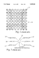
- FIG. 1 is a block level schematic diagram of one possible mesh topology showing a computer network and the computer network interconnect 10.
- FIG. 2 is a block level schematic diagram showing network connections to a node in the computer network of FIG. 1.
- Each node is a switch element, e.g. those elements identified by numeric designators 11 and 12, that contains two or more packet buffers.
- FIG. 3 is a block level schematic diagram showing a buffer arrangement used in the node of FIG. 2.
- the use of packet buffers 31, 32, 33 makes it possible for a switch element 11 to route multiple packets that are received at the switch to a neighboring switch element 12 via the same connection over which the packets were received. In such a case, the switch routes one of the packets out of the switch, while the remaining packets are stored within the packet buffers. When the desired connecting link becomes free again, the switch element forwards another packet over the link from one of the packet buffers. The process repeats until all of the packets stored in the packet buffers are forwarded.
- Packet buffers represent a basic interconnect resource. If more free buffers are available throughout the network fabric at any given time, it is more likely that the network fabric can route packets to their destinations with a minimum amount of delay. Unfortunately, under certain traffic conditions the supply of buffers within a packet switch can become exhausted. When this happens, the performance of the packet switch is degraded such that little, if any, useful work is accomplished by the switch.
- One known method for controlling interconnect flow is to ignore messages that cannot be buffered for lack of switch resources. In this method, if the traffic load consumes all of the available packet buffer resources at a switch, the switch discards any incoming packet that it cannot buffer.
- Sender clients are permitted to inject packets continually into an already congested network fabric mesh. It is possible that one single sending client can consume the entire interconnect bandwidth and buffer space.
- a group of sender clients could conspire to send messages to a single target. Because the maximum rate at which a single node can remove packets from the interconnect is much less than the potential aggregate rate at which multiple sender clients can inject packets into the interconnect toward that single node, the interconnect resources would become exhausted.
- An adaptive credit routing mechanism has been proposed for use in limiting global interconnect saturation. This approach limits both the number of nodes and the location of nodes that can be flooded by a particular individual sender.
- the set of affected nodes along the path from the sender client to the receiver client are defined as a plume.
- the size of the plume is directly related to the number of credits that are issued to each packet of a message. Thus, if more credits are issued to a packet, a bigger plume results; while in-order delivery, i.e. a single path from the sender client to receiver client, produces a smaller plume.
- the foregoing method does not require a global flow control mechanism, and it is therefore simple and fast.
- it allows the interconnect to route a packet around hot spots located inside that portion of the subplume where adaptation is allowed.
- the intermediate nodes inside the plume are still eventually consumed, resulting in plume saturation.
- the rest of the interconnect might remain unaffected and available for useful work.
- the saturated plume would interfere with traffic that either needed to cross it or reach a target inside of it.
- Such interconnect flow control problems limit resources available to a network user and prevent the most efficient, fair, and orderly use of a network interconnect, especially where there is no mechanism for allocating resources among the many network users.
- the invention is based on a new concept, i.e. that of related packets.
- Packets are defined to be related to each other if there is some reason to consider the group of packets as part of some greater entity.
- the concept of relatedness can manifest itself in a variety of ways. For example, a group of packets may be considered to be related if they are subparts of a single message. Packets could also be defined to be related if they originated from the same computer, or even if they originated from a different computer, but are all targeted at the same destination computer.
- a packet is stalled if it is stuck inside a switch packet buffer waiting to be forwarded due to unavailability of appropriate output ports.
- the switch checks to see if its internal packet buffers already contain a related packet that is currently stalled. If so, the switch immediately rejects the incoming packet. The incoming packet is only accepted if there are no related packets stalled inside the receiver.
- a switch may simultaneously contain several related packets that are in the process of being forwarded, but it may never contain more than one stalled packet. In simple terms, if a switch already contains a request to do something that it is currently unable to do, the invention does not allow the switch to accept another packet requiring an identical operation. Thus, the other buffers inside the switch remain free to be allocated to do things that may still be possible, i.e. process cross traffic through a stalled plume.
- a previously stalled packet begins to leave a switch, its associated buffer continues to be marked as stalled until such time as the sender client knows that the receiver client can not reject the packet due to buffer allocation problems. This prevents the sender client from accepting another similar packet until it is sure that it is actually able to forward the one it already has.
- the invention puts a hard limit on the number of packet buffers that any given related data stream can allocate within the interconnect. Allowing a single stalled buffer per intermediate switch is enough to ensure that the performance benefits from pipelining effects are not lost. As soon as a forwarding operation finishes, a stalled packet may be forwarded and a new related packet may be simultaneously accepted to become the next stalled packet.
- the invention herein begins to throttle the sender client under congested conditions much faster than any previous method. In fact, when in-order delivery is used, the congestion effects propagate back to throttle the sender in minimal time.
- a switch inside the plume only rejects packets when it already contains stalled packets.
- the plume fills just as rapidly as with the original methods.
- intermediate switch nodes may be able to support multiple simultaneous forwarding operations which rapidly fills the plume.
- stalled packets may begin to appear in the plume propagating from the destination back to the source.
- the injection switch contains a stalled related packet, it refuses to accept any more related packets for injection into the interconnect, effectively throttling the injection process.
- the destination node removes packets, the fact that each node in the plume may already contain a stalled packet ensures that pipelining effects begin immediately as required.
- FIG. 1 is a block level schematic diagram of a diagonal mesh topology showing a computer network and the computer network interconnect;
- FIG. 2 is a block level schematic diagram showing network connections to a node in the computer network of FIG. 1;
- FIG. 3 is a block level schematic diagram showing a buffer arrangement used in the node of FIG. 2;
- FIG. 4 is a block level schematic diagram of a flow control mechanism for a packet-switched computer network interconnect according to the invention
- FIG. 5 is a block level schematic diagram of a switch packet buffer for the packet-switched computer network interconnect shown in FIG. 4;
- FIG. 6 is a flow diagram for a flow control mechanism for a packet-switched computer network interconnect according to the invention.
- FIG. 7 shows the format of a packet that includes a credit count field and a tag field.
- the invention provides a method of computer network interconnect flow control in which the interconnect hardware constrains the amount of general interconnect resources that are available to any given interconnect user.
- the method constrains the adaptivity of packets moving through the switch fabric. Such adaptivity can improve interconnect performance under certain interconnect traffic patterns. However, if such adaptivity is unconstrained the packets can be routed far from their destination. This roundabout packet routing interferes with other traffic in the network fabric. In the worst case, unconstrained adaptivity allows a single sender/receiver client pair to consume all of the available packet buffers in the network fabric.
- damped adaptivity One aspect of the invention avoids the foregoing problem by limiting adaptivity, referred to herein as damped adaptivity.
- a damped adaptive router requires that the header of each packet routed through the interconnect contain a field referred to as the adaptive credit count.
- the injecting hardware or software writes a numeric value into the adaptive credit count corresponding to the initial credit. If the value of the credit count is positive upon entering a packet switch, the switch is allowed to forward the packet in an adaptive manner. If the field is zero, the packet switch is constrained to route the packet in a nonadaptive manner.
- the credit count may be decremented in at least one of at least two fashions, i.e. whenever the packet switch forwards a packet via an adaptive route, or whenever a packet is forwarded via any route. In either case, picking the initial value of the credit count to be less than the maximum diameter of the switch fabric limits the number and location of the set of packet switches that could possibly be visited by packets from a particular sender/receiver client pair. The set of packet switches that could be visited is referred to as the "plume”. Placing a small initial value in the adaptive count field in relation to the diameter of the interconnect produces a smaller plume.
- a single sender client sending to a single receiver client cannot use up more interconnect resources than are contained within the adaptive plume of the packet switches between the sender client and the receiver client.
- Sender/receiver client plumes that do not overlap can communicate without any contention.
- a sender client is still allowed to consume all of the fabric resources within the plume. This is not always desirable because it is likely that cross traffic from another sender/receiver pair will overlap another plume, and therefore compete for resources within the area described by the intersection of the two plumes.
- the packet switch in the invention constrains the number of packet buffers that are available within a particular plume.
- the invention provides a mechanism in which a switch that contains a packet that it cannot currently forward, i.e. a stalled packet, is not required to accept another incoming packet that requires the same forwarding operation, for example for a packet that is somehow related to the stalled packet. This mechanism limits the number of packet buffers within a switch that may hold packets from the same plume.
- FIG. 4 is a block level schematic diagram of a flow control mechanism for a packet-switched computer network interconnect according to the invention.
- a switch is shown having a number of connections to a network, which in turn connect the switch to other nodes 12-17 in the network.
- Each network connection is connected to a series of switch packet buffers 31-36 via a cross bar switch 38.
- a router 40 connected to the packet buffers coordinates the receipt of traffic at, and forwarding of traffic through, the switch such that packets are forwarded to the appropriate destination.
- a content addressable memory (CAM) 50 is arranged to hold the packet relationship tag for each packet in each packet buffer. In this way, a buffer containing a stalled packet stores a packet relationship tag in the CAM, indicating that any incoming packet having a matching tag should be refused by the switch.
- CAM content addressable memory
- FIG. 5 is a block level schematic diagram of a packet switch buffer of the packet-switched computer network interconnect shown in FIG. 4.
- Each packet buffer 31, 36 includes a sufficient amount of storage capacity to hold a packet.
- the packet buffers hold the packet relationship tag, and a flag that indicates the packet buffer status, i.e. busy, free, stalled/forwarding.
- the invention provides an element that generates information about the packet contained in the packet buffers, and includes a mechanism in the packet switch that analyzes the information, and thereby regulates the flow of incoming packet traffic.
- the invention also includes a mechanism that adds state information to each packet buffer in a switch element. This information indicates whether there is a packet inside a buffer or not. If a buffer contains a packet, the mechanism also generates state information that indicates whether the packet is currently being forwarded, or if it is stalled in the buffer and waiting to be forwarded.
- the mechanism associates a tag with each packet buffer in a packet switch.
- the tag is a numeric value.
- the values assigned to the tag field define the relationship between packets, i.e. like values represent related packets, while unlike values represent unrelated packets.
- the actual values chosen to represent particular relationships are a matter of choice, except that there should be mutual agreement on the values by the various users of the interconnect.
- the tag defines the relationship code of the packet in the buffer.
- a tag may be based on, but is not limited to:
- An alternative embodiment of the invention adds a special tag field within the packet header that is constructed by the system hardware or software before the packet is initially injected into the switch fabric.
- An additional embodiment of the invention splits the tag field into two or more smaller tag subfields, These subfields act in the same manner as the large single field tag, except that the match outputs from the tag subcomparisons may be logically ANDed or ORed together to make more complicated comparisons possible. If the subfields are ANDed together, the result makes the overall possibility of matching less restrictive. If the subfields are ORed together, the possibility of matching becomes more restrictive.
- one tag field is used to define various types of traffic, e.g. priority level: high, medium, or low, and the other tag field is used in one of the manners described above. If the matches from the tag subfields are ANDed together to generate a final match signal, the final match would effectively require that packets be related in the manner specified by the second tag field AND that they have the same priority level. If an OR operation is performed on the tag subfields, the switch would reject any packets that belonged to the same traffic type. In the example regarding traffic types, an OR operation ensures that a switch never devotes all of its buffers to a single traffic type.
- the tags represent a means of grouping packets that are normally considered separate entities into a set of related packets to accomplish flow control.
- the tag generation and checking mechanisms are known, and therefore are not discussed in detail herein.
- the basic elements of the invention include:
- Switch packet headers must contain either information that the switch could use to construct a tag, or an explicit tag constructed by an external agent.
- Switch packet buffers need a flag that marks them as stalled or as being forwarded.
- the switch must contain a CAM (Content Addressable Memory) having an entry for each packet buffer.
- the data stored in the CAM corresponds to the tag information contained in the header.
- the CAM must enable a fast check of the stalled packet buffers to determine if the tag in question already existed.
- the size of the CAM is minimal because it only needs space one entry per packet buffer.
- a receiving switch must support some sort of non-destructive means of rejecting incoming packet traffic. This means that if the sending switch has a packet transfer rejected by the receiving switch, the sender retains the original packet data so that it may try again at some later point in time.
- FIG. 6 is a flow diagram for a flow control mechanism for a packet-switched computer network interconnect according to the invention.
- the inventive congestion control mechanism operates as follows: when a packet arrives (100), the receiving switch searches the set of all of its packet buffers that currently contain stalled packets (102).
- the preferred embodiment of the invention employs a B word by T bit Content Addressable Memory (CAM), where B is the number of buffers in the switch and T is the number of bits in the tag. If there are no buffers with stalled packets (104), or if those buffers containing stalled packets do not match the tag of the incoming packet (106), the packet switch accepts the incoming packet (108) and attempts to forward the packet to its destination (110).
- CAM Content Addressable Memory
- the packet switch refuses to accept the incoming packet (112).
- the packet is not dropped by the sender, it is just not accepted by the receiver switch, possibly causing the packet to stall at the sender.
- the switch By refusing to accept the packet, the switch causes a plume to form because subsequent packets begin to stall within some of the upstream switches. If the condition persists long enough for the packets to stall all the way back to the injection point, the switch at the injection point can use the same mechanism to refuse accepting injection packets. This acts as a back pressure signal for the overall flow control mechanism.
- the mechanism herein is not required to drop packets when the interconnect gets busy.
- the back pressure from the flow control system keeps traffic from entering the fabric. This improves performance by keeping traffic that can not be routed out of the fabric, thereby allowing more of the interconnect resources to be used to forward packets in a useful manner.
- One advantage of the invention herein over the credit based schemes discussed above allows the interconnect a fine grain method of allocating its packet buffer resources because the packet tag field described represents an extremely flexible method of defining the sorts of interconnect packet traffic that should be considered by a switch element as being parts of the same piece of metatraffic. Credit based schemes can only provide a method of determining whether or not the basic buffer resources exist in their neighbors.
- the invention herein also allows an interconnect designer to tune the flow control mechanism for the traffic loads.
- the size of the plume can be adjusted via the adaptive credit count. Larger plumes mean more adaptivity, but a longer time before the back pressure signal propagates back to the injection point.
- Picking appropriate tags to define the relationship between packets specifies a limit on the amount of buffer resources that any given switch can use at any other given switch. A more specific definition of the relation between the various packets allows more resources to be consumed in other switches.
- an interconnect designer can tune the parameters to best suit expected traffic loads.
- the most restrictive tag scheme provides a tag that is the same whenever a packet is injected anywhere in the fabric. In this case, no switch may contain more than one stalled packet and one forwarding packet.
- tags are selected such that the number of unique tags describing the set of packets floating around the fabric is roughly the same as the total number of buffers in the fabric divided by two because each tag can consume two buffers, i.e. one stalled buffer and one forwarding buffer.
- tags it is useful to allow slightly more tags than are in simultaneous use because it can be advantageous to allow temporary traffic overloads. If the overload persists, the flow control mechanism herein described eventually shuts it down.
- the switch permits the packets to be injected.
- the switch is able to for forward the packets, it is not particularly congested.
- the switch contains one packet from a message that gets stalled, further injection is throttled.
- the invention herein enables setting hard limits to the amount of interconnect resource accessible to a single sender.
Abstract
Description
Claims (7)
Priority Applications (4)
| Application Number | Priority Date | Filing Date | Title |
|---|---|---|---|
| US08/296,215 US5699520A (en) | 1994-08-25 | 1994-08-25 | Flow control apparatus and method for a computer interconnect using adaptive credits and flow control tags |
| DE19526962A DE19526962C2 (en) | 1994-08-25 | 1995-07-24 | Flow control mechanism for a packet switched computer connection |
| GB9517344A GB2292656A (en) | 1994-08-25 | 1995-08-24 | Computer flow control mechanism |
| JP21614095A JPH0879306A (en) | 1994-08-25 | 1995-08-24 | Flow control device for computer interconnection |
Applications Claiming Priority (1)
| Application Number | Priority Date | Filing Date | Title |
|---|---|---|---|
| US08/296,215 US5699520A (en) | 1994-08-25 | 1994-08-25 | Flow control apparatus and method for a computer interconnect using adaptive credits and flow control tags |
Publications (1)
| Publication Number | Publication Date |
|---|---|
| US5699520A true US5699520A (en) | 1997-12-16 |
Family
ID=23141082
Family Applications (1)
| Application Number | Title | Priority Date | Filing Date |
|---|---|---|---|
| US08/296,215 Expired - Lifetime US5699520A (en) | 1994-08-25 | 1994-08-25 | Flow control apparatus and method for a computer interconnect using adaptive credits and flow control tags |
Country Status (4)
| Country | Link |
|---|---|
| US (1) | US5699520A (en) |
| JP (1) | JPH0879306A (en) |
| DE (1) | DE19526962C2 (en) |
| GB (1) | GB2292656A (en) |
Cited By (21)
| Publication number | Priority date | Publication date | Assignee | Title |
|---|---|---|---|---|
| US20030035427A1 (en) * | 2001-08-14 | 2003-02-20 | Mehdi Alasti | Method and apparatus for arbitration scheduling with a penalty for a switch fabric |
| EP1361710A2 (en) * | 2002-05-09 | 2003-11-12 | Altima Communications, Inc. | A fairness scheme method and apparatus for pause capable and pause incapable ports |
| US20040073704A1 (en) * | 2002-10-15 | 2004-04-15 | Nomadix, Inc. | Intelligent network address translator and methods for network address translation |
| US6754206B1 (en) * | 1997-12-04 | 2004-06-22 | Alcatel Usa Sourcing, L.P. | Distributed telecommunications switching system and method |
| US6757246B2 (en) | 2001-08-14 | 2004-06-29 | Pts Corporation | Method and apparatus for weighted arbitration scheduling separately at the input ports and the output ports of a switch fabric |
| US7324442B1 (en) * | 2000-02-28 | 2008-01-29 | The Board Of Trustees Of The Leland Stanford Junior University | Active queue management toward fair bandwidth allocation |
| US20080148383A1 (en) * | 2006-09-29 | 2008-06-19 | Balaji Pitchaikani | Systems and methods for injecting content |
| US20090113082A1 (en) * | 2007-10-31 | 2009-04-30 | Etai Adar | Device, System, and Method of Speculative Packet Transmission |
| US20110030037A1 (en) * | 2009-07-07 | 2011-02-03 | Vadim Olshansky | Zone migration in network access |
| US8027339B2 (en) | 1997-03-12 | 2011-09-27 | Nomadix, Inc. | System and method for establishing network connection |
| US20110258637A1 (en) * | 2010-04-15 | 2011-10-20 | Jan Bezdicek | Systems and methods for conducting communications among components of multidomain industrial automation system |
| US8156246B2 (en) | 1998-12-08 | 2012-04-10 | Nomadix, Inc. | Systems and methods for providing content and services on a network system |
| US20120087375A1 (en) * | 2010-10-07 | 2012-04-12 | Korea Advanced Institute Of Science And Technology | Packet switching system and method |
| US8190708B1 (en) | 1999-10-22 | 2012-05-29 | Nomadix, Inc. | Gateway device having an XML interface and associated method |
| US20120182917A1 (en) * | 2009-09-16 | 2012-07-19 | St. Jude Medical Ab | Implantable medical device communication |
| US8266269B2 (en) | 1998-12-08 | 2012-09-11 | Nomadix, Inc. | Systems and methods for providing content and services on a network system |
| US8613053B2 (en) | 1998-12-08 | 2013-12-17 | Nomadix, Inc. | System and method for authorizing a portable communication device |
| US8964771B2 (en) | 2005-04-15 | 2015-02-24 | Altera Corporation | Method and apparatus for scheduling in a packet buffering network |
| US9118578B2 (en) | 2011-01-18 | 2015-08-25 | Nomadix, Inc. | Systems and methods for group bandwidth management in a communication systems network |
| US9392072B2 (en) | 2010-04-15 | 2016-07-12 | Rockwell Automation Technologies, Inc. | Systems and methods for conducting communications among components of multidomain industrial automation system |
| US9411757B2 (en) | 2011-03-14 | 2016-08-09 | Hewlett Packard Enterprise Development Lp | Memory interface |
Families Citing this family (1)
| Publication number | Priority date | Publication date | Assignee | Title |
|---|---|---|---|---|
| US6026093A (en) * | 1997-10-02 | 2000-02-15 | Sun Microsystems, Inc. | Mechanism for dispatching data units via a telecommunications network |
Citations (9)
| Publication number | Priority date | Publication date | Assignee | Title |
|---|---|---|---|---|
| EP0219049A2 (en) * | 1985-10-07 | 1987-04-22 | Nec Corporation | High-speed packet-switched communications system with end-to-end flow control and retransmission |
| EP0281757A2 (en) * | 1987-03-09 | 1988-09-14 | Hitachi, Ltd. | Message transfer system and method |
| US5010516A (en) * | 1988-01-11 | 1991-04-23 | Texas Instruments Incorporated | Content addressable memory |
| US5088091A (en) * | 1989-06-22 | 1992-02-11 | Digital Equipment Corporation | High-speed mesh connected local area network |
| US5193151A (en) * | 1989-08-30 | 1993-03-09 | Digital Equipment Corporation | Delay-based congestion avoidance in computer networks |
| US5253248A (en) * | 1990-07-03 | 1993-10-12 | At&T Bell Laboratories | Congestion control for connectionless traffic in data networks via alternate routing |
| EP0577359A2 (en) * | 1992-06-30 | 1994-01-05 | AT&T Corp. | Congestion control in high speed networks |
| US5282270A (en) * | 1990-06-06 | 1994-01-25 | Apple Computer, Inc. | Network device location using multicast |
| US5493566A (en) * | 1992-12-15 | 1996-02-20 | Telefonaktiebolaget L M. Ericsson | Flow control system for packet switches |
-
1994
- 1994-08-25 US US08/296,215 patent/US5699520A/en not_active Expired - Lifetime
-
1995
- 1995-07-24 DE DE19526962A patent/DE19526962C2/en not_active Expired - Fee Related
- 1995-08-24 JP JP21614095A patent/JPH0879306A/en not_active Withdrawn
- 1995-08-24 GB GB9517344A patent/GB2292656A/en not_active Withdrawn
Patent Citations (9)
| Publication number | Priority date | Publication date | Assignee | Title |
|---|---|---|---|---|
| EP0219049A2 (en) * | 1985-10-07 | 1987-04-22 | Nec Corporation | High-speed packet-switched communications system with end-to-end flow control and retransmission |
| EP0281757A2 (en) * | 1987-03-09 | 1988-09-14 | Hitachi, Ltd. | Message transfer system and method |
| US5010516A (en) * | 1988-01-11 | 1991-04-23 | Texas Instruments Incorporated | Content addressable memory |
| US5088091A (en) * | 1989-06-22 | 1992-02-11 | Digital Equipment Corporation | High-speed mesh connected local area network |
| US5193151A (en) * | 1989-08-30 | 1993-03-09 | Digital Equipment Corporation | Delay-based congestion avoidance in computer networks |
| US5282270A (en) * | 1990-06-06 | 1994-01-25 | Apple Computer, Inc. | Network device location using multicast |
| US5253248A (en) * | 1990-07-03 | 1993-10-12 | At&T Bell Laboratories | Congestion control for connectionless traffic in data networks via alternate routing |
| EP0577359A2 (en) * | 1992-06-30 | 1994-01-05 | AT&T Corp. | Congestion control in high speed networks |
| US5493566A (en) * | 1992-12-15 | 1996-02-20 | Telefonaktiebolaget L M. Ericsson | Flow control system for packet switches |
Non-Patent Citations (6)
| Title |
|---|
| Cerf, Kahn; "A Protocol for Packet Network Intercommunication"; IEEE Transactions on Communications, vol. COM-22, No. 5, May 1974, pp. 637-648. |
| Cerf, Kahn; A Protocol for Packet Network Intercommunication ; IEEE Transactions on Communications, vol. COM 22, No. 5, May 1974, pp. 637 648. * |
| Dixon et al, "Data Link Switching: Switch-to-Switch Protocol", IBM, RFC 1434, Mar. 1993 pp. 1-33. |
| Dixon et al, Data Link Switching: Switch to Switch Protocol , IBM, RFC 1434, Mar. 1993 pp. 1 33. * |
| Sendix: Datensuche im Eiltemp. In: Electronik Oct. 1992, pp. 50 62. * |
| Sendix: Datensuche im Eiltemp. In: Electronik Oct. 1992, pp. 50-62. |
Cited By (64)
| Publication number | Priority date | Publication date | Assignee | Title |
|---|---|---|---|---|
| US8594107B2 (en) | 1997-03-12 | 2013-11-26 | Nomadix, Inc. | System and method for establishing network connection |
| US8027339B2 (en) | 1997-03-12 | 2011-09-27 | Nomadix, Inc. | System and method for establishing network connection |
| US6754206B1 (en) * | 1997-12-04 | 2004-06-22 | Alcatel Usa Sourcing, L.P. | Distributed telecommunications switching system and method |
| US8606917B2 (en) | 1998-12-08 | 2013-12-10 | Nomadix, Inc. | Systems and methods for providing content and services on a network system |
| US10110436B2 (en) | 1998-12-08 | 2018-10-23 | Nomadix, Inc. | Systems and methods for providing content and services on a network system |
| US8725899B2 (en) | 1998-12-08 | 2014-05-13 | Nomadix, Inc. | Systems and methods for providing content and services on a network system |
| US8713641B1 (en) | 1998-12-08 | 2014-04-29 | Nomadix, Inc. | Systems and methods for authorizing, authenticating and accounting users having transparent computer access to a network using a gateway device |
| US8613053B2 (en) | 1998-12-08 | 2013-12-17 | Nomadix, Inc. | System and method for authorizing a portable communication device |
| US8788690B2 (en) | 1998-12-08 | 2014-07-22 | Nomadix, Inc. | Systems and methods for providing content and services on a network system |
| US9548935B2 (en) | 1998-12-08 | 2017-01-17 | Nomadix, Inc. | Systems and methods for providing content and services on a network system |
| US8725888B2 (en) | 1998-12-08 | 2014-05-13 | Nomadix, Inc. | Systems and methods for providing content and services on a network system |
| US8370477B2 (en) | 1998-12-08 | 2013-02-05 | Nomadix, Inc. | Systems and methods for providing content and services on a network system |
| US8364806B2 (en) | 1998-12-08 | 2013-01-29 | Nomadix, Inc. | Systems and methods for providing content and services on a network system |
| US8266269B2 (en) | 1998-12-08 | 2012-09-11 | Nomadix, Inc. | Systems and methods for providing content and services on a network system |
| US8266266B2 (en) | 1998-12-08 | 2012-09-11 | Nomadix, Inc. | Systems and methods for providing dynamic network authorization, authentication and accounting |
| US8244886B2 (en) | 1998-12-08 | 2012-08-14 | Nomadix, Inc. | Systems and methods for providing content and services on a network system |
| US9160672B2 (en) | 1998-12-08 | 2015-10-13 | Nomadix, Inc. | Systems and methods for controlling user perceived connection speed |
| US10341243B2 (en) | 1998-12-08 | 2019-07-02 | Nomadix, Inc. | Systems and methods for providing content and services on a network system |
| US8156246B2 (en) | 1998-12-08 | 2012-04-10 | Nomadix, Inc. | Systems and methods for providing content and services on a network system |
| US8190708B1 (en) | 1999-10-22 | 2012-05-29 | Nomadix, Inc. | Gateway device having an XML interface and associated method |
| US8516083B2 (en) | 1999-10-22 | 2013-08-20 | Nomadix, Inc. | Systems and methods of communicating using XML |
| US7324442B1 (en) * | 2000-02-28 | 2008-01-29 | The Board Of Trustees Of The Leland Stanford Junior University | Active queue management toward fair bandwidth allocation |
| US6757246B2 (en) | 2001-08-14 | 2004-06-29 | Pts Corporation | Method and apparatus for weighted arbitration scheduling separately at the input ports and the output ports of a switch fabric |
| US6990072B2 (en) | 2001-08-14 | 2006-01-24 | Pts Corporation | Method and apparatus for arbitration scheduling with a penalty for a switch fabric |
| US20030035427A1 (en) * | 2001-08-14 | 2003-02-20 | Mehdi Alasti | Method and apparatus for arbitration scheduling with a penalty for a switch fabric |
| US20030210651A1 (en) * | 2002-05-09 | 2003-11-13 | Altima Communications Inc. | Fairness scheme method and apparatus for pause capable and pause incapable ports |
| US20090010160A1 (en) * | 2002-05-09 | 2009-01-08 | Broadcom Corporation | Fairness scheme method and apparatus for pause capable and pause incapable ports |
| EP1361710A2 (en) * | 2002-05-09 | 2003-11-12 | Altima Communications, Inc. | A fairness scheme method and apparatus for pause capable and pause incapable ports |
| EP1361710A3 (en) * | 2002-05-09 | 2006-05-10 | Altima Communications, Inc. | A fairness scheme method and apparatus for pause capable and pause incapable ports |
| US7423967B2 (en) * | 2002-05-09 | 2008-09-09 | Broadcom Corporation | Fairness scheme method and apparatus for pause capable and pause incapable ports |
| US10979385B2 (en) | 2002-10-15 | 2021-04-13 | Nomadix, Inc. | Systems and methods for network address translation |
| US8832315B2 (en) | 2002-10-15 | 2014-09-09 | Nomadix, Inc. | Systems and methods for network address translation |
| US8370524B2 (en) | 2002-10-15 | 2013-02-05 | Nomadix, Inc. | Systems and methods for network address translation |
| US10291580B2 (en) | 2002-10-15 | 2019-05-14 | Nomadix, Inc. | Systems and methods for network address translation |
| US7752334B2 (en) | 2002-10-15 | 2010-07-06 | Nomadix, Inc. | Intelligent network address translator and methods for network address translation |
| US9491136B2 (en) | 2002-10-15 | 2016-11-08 | Nomadix, Inc. | Systems and methods for network address translation |
| US8234409B2 (en) | 2002-10-15 | 2012-07-31 | Nomadix, Inc. | Intelligent network address translator and methods for network address translation |
| US7822873B1 (en) | 2002-10-15 | 2010-10-26 | Nomadix, Inc. | Intelligent network address translator and methods for network address translation |
| US20110035479A1 (en) * | 2002-10-15 | 2011-02-10 | Nomadix, Inc. | Intelligent network address translator and methods for network address translation |
| US8051206B2 (en) | 2002-10-15 | 2011-11-01 | Nomadix, Inc. | Intelligent network address translator and methods for network address translation |
| US20040073704A1 (en) * | 2002-10-15 | 2004-04-15 | Nomadix, Inc. | Intelligent network address translator and methods for network address translation |
| US20100272109A1 (en) * | 2002-10-15 | 2010-10-28 | Nomadix, Inc. | Intellegent network address translator and methods for network address translation |
| US8964771B2 (en) | 2005-04-15 | 2015-02-24 | Altera Corporation | Method and apparatus for scheduling in a packet buffering network |
| US10778787B2 (en) | 2006-09-29 | 2020-09-15 | Nomadix, Inc. | Systems and methods for injecting content |
| US11272019B2 (en) | 2006-09-29 | 2022-03-08 | Nomadix, Inc. | Systems and methods for injecting content |
| US8868740B2 (en) | 2006-09-29 | 2014-10-21 | Nomadix, Inc. | Systems and methods for injecting content |
| US20080148383A1 (en) * | 2006-09-29 | 2008-06-19 | Balaji Pitchaikani | Systems and methods for injecting content |
| US9330400B2 (en) | 2006-09-29 | 2016-05-03 | Nomadix, Inc. | Systems and methods for injecting content |
| US7827325B2 (en) * | 2007-10-31 | 2010-11-02 | International Business Machines Corporation | Device, system, and method of speculative packet transmission |
| US20090113082A1 (en) * | 2007-10-31 | 2009-04-30 | Etai Adar | Device, System, and Method of Speculative Packet Transmission |
| US20110030037A1 (en) * | 2009-07-07 | 2011-02-03 | Vadim Olshansky | Zone migration in network access |
| US10873858B2 (en) | 2009-07-07 | 2020-12-22 | Nomadix, Inc. | Zone migration in network access |
| US9894035B2 (en) | 2009-07-07 | 2018-02-13 | Nomadix, Inc. | Zone migration in network access |
| US8566912B2 (en) | 2009-07-07 | 2013-10-22 | Nomadix, Inc. | Zone migration in network access |
| US9141773B2 (en) | 2009-07-07 | 2015-09-22 | Nomadix, Inc. | Zone migration in network access |
| US20120182917A1 (en) * | 2009-09-16 | 2012-07-19 | St. Jude Medical Ab | Implantable medical device communication |
| US20110258637A1 (en) * | 2010-04-15 | 2011-10-20 | Jan Bezdicek | Systems and methods for conducting communications among components of multidomain industrial automation system |
| US9392072B2 (en) | 2010-04-15 | 2016-07-12 | Rockwell Automation Technologies, Inc. | Systems and methods for conducting communications among components of multidomain industrial automation system |
| US8984533B2 (en) * | 2010-04-15 | 2015-03-17 | Rockwell Automation Technologies, Inc. | Systems and methods for conducting communications among components of multidomain industrial automation system |
| US20120087375A1 (en) * | 2010-10-07 | 2012-04-12 | Korea Advanced Institute Of Science And Technology | Packet switching system and method |
| US8792514B2 (en) * | 2010-10-07 | 2014-07-29 | Korea Advanced Institute Of Science And Technology | Packet switching system and method |
| US9118578B2 (en) | 2011-01-18 | 2015-08-25 | Nomadix, Inc. | Systems and methods for group bandwidth management in a communication systems network |
| US11949562B2 (en) | 2011-01-18 | 2024-04-02 | Nomadix, Inc. | Systems and methods for group bandwidth management in a communication systems network |
| US9411757B2 (en) | 2011-03-14 | 2016-08-09 | Hewlett Packard Enterprise Development Lp | Memory interface |
Also Published As
| Publication number | Publication date |
|---|---|
| DE19526962A1 (en) | 1996-02-29 |
| DE19526962C2 (en) | 1998-09-17 |
| GB9517344D0 (en) | 1995-10-25 |
| JPH0879306A (en) | 1996-03-22 |
| GB2292656A (en) | 1996-02-28 |
Similar Documents
| Publication | Publication Date | Title |
|---|---|---|
| US5699520A (en) | Flow control apparatus and method for a computer interconnect using adaptive credits and flow control tags | |
| US8174978B2 (en) | Method for congestion management of a network, a signalling protocol, a switch, an end station and a network | |
| US7433363B2 (en) | Low latency switch architecture for high-performance packet-switched networks | |
| US20210294762A1 (en) | Procedures for improving efficiency of an interconnect fabric on a system on chip | |
| Ngai et al. | A framework for adaptive routing in multicomputer networks | |
| US6304552B1 (en) | Memory and apparatus for input based control of discards in a lossy packet network | |
| US7623455B2 (en) | Method and apparatus for dynamic load balancing over a network link bundle | |
| CN1770734B (en) | Traffic control method for network equipment | |
| US5511168A (en) | Virtual circuit manager for multicast messaging | |
| US6920147B2 (en) | Input buffering and queue status-based output control for a digital traffic switch | |
| RU2565781C2 (en) | Providing bufferless transport method for multi-dimensional mesh topology | |
| US20020141427A1 (en) | Method and apparatus for a traffic optimizing multi-stage switch fabric network | |
| US7773616B2 (en) | System and method for communicating on a richly connected multi-processor computer system using a pool of buffers for dynamic association with a virtual channel | |
| JPH07221754A (en) | Communication system for load balance and load dispersion | |
| US8509077B2 (en) | Method for congestion management of a network, a switch, and a network | |
| KR20070007769A (en) | Highly parallel switching systems utilizing error correction | |
| US7889729B2 (en) | System and method for reevaluating granted arbitrated bids | |
| JP2001292164A (en) | Packet switch and its switching method | |
| US7773618B2 (en) | System and method for preventing deadlock in richly-connected multi-processor computer system using dynamic assignment of virtual channels | |
| US20080159138A1 (en) | Methods and devices for providing ingress routing in selective randomized load balancing | |
| US7609693B2 (en) | Multicast packet queuing | |
| US7079545B1 (en) | System and method for simultaneous deficit round robin prioritization | |
| Petrini et al. | Performance analysis of minimal adaptive wormhole routing with time-dependent deadlock recovery | |
| KR20030026929A (en) | Packetized data discard | |
| US7773617B2 (en) | System and method for arbitration for virtual channels to prevent livelock in a richly-connected multi-processor computer system |
Legal Events
| Date | Code | Title | Description |
|---|---|---|---|
| AS | Assignment |
Owner name: HEWLETT-PACKARD COMPANY, CALIFORNIA Free format text: ASSIGNMENT OF ASSIGNORS INTEREST;ASSIGNORS:HODGSON, ROBIN;DAVIS, ALAN;REEL/FRAME:007169/0511;SIGNING DATES FROM 19940812 TO 19940822 |
|
| STCF | Information on status: patent grant |
Free format text: PATENTED CASE |
|
| FEPP | Fee payment procedure |
Free format text: PAYER NUMBER DE-ASSIGNED (ORIGINAL EVENT CODE: RMPN); ENTITY STATUS OF PATENT OWNER: LARGE ENTITY Free format text: PAYOR NUMBER ASSIGNED (ORIGINAL EVENT CODE: ASPN); ENTITY STATUS OF PATENT OWNER: LARGE ENTITY |
|
| AS | Assignment |
Owner name: HEWLETT-PACKARD COMPANY, COLORADO Free format text: MERGER;ASSIGNOR:HEWLETT-PACKARD COMPANY;REEL/FRAME:011523/0469 Effective date: 19980520 |
|
| FPAY | Fee payment |
Year of fee payment: 4 |
|
| FPAY | Fee payment |
Year of fee payment: 8 |
|
| FPAY | Fee payment |
Year of fee payment: 12 |
|
| AS | Assignment |
Owner name: HEWLETT-PACKARD DEVELOPMENT COMPANY, L.P., TEXAS Free format text: ASSIGNMENT OF ASSIGNORS INTEREST;ASSIGNOR:HEWLETT-PACKARD COMPANY;REEL/FRAME:026945/0699 Effective date: 20030131 |