US5707139A - Vertical cavity surface emitting laser arrays for illumination - Google Patents
Vertical cavity surface emitting laser arrays for illumination Download PDFInfo
- Publication number
- US5707139A US5707139A US08/548,346 US54834695A US5707139A US 5707139 A US5707139 A US 5707139A US 54834695 A US54834695 A US 54834695A US 5707139 A US5707139 A US 5707139A
- Authority
- US
- United States
- Prior art keywords
- source
- elements
- vcsel
- chip
- illumination
- Prior art date
- Legal status (The legal status is an assumption and is not a legal conclusion. Google has not performed a legal analysis and makes no representation as to the accuracy of the status listed.)
- Expired - Lifetime
Links
Images

Classifications
-
- H—ELECTRICITY
- H01—ELECTRIC ELEMENTS
- H01S—DEVICES USING THE PROCESS OF LIGHT AMPLIFICATION BY STIMULATED EMISSION OF RADIATION [LASER] TO AMPLIFY OR GENERATE LIGHT; DEVICES USING STIMULATED EMISSION OF ELECTROMAGNETIC RADIATION IN WAVE RANGES OTHER THAN OPTICAL
- H01S5/00—Semiconductor lasers
- H01S5/40—Arrangement of two or more semiconductor lasers, not provided for in groups H01S5/02 - H01S5/30
- H01S5/42—Arrays of surface emitting lasers
- H01S5/423—Arrays of surface emitting lasers having a vertical cavity
-
- F—MECHANICAL ENGINEERING; LIGHTING; HEATING; WEAPONS; BLASTING
- F21—LIGHTING
- F21K—NON-ELECTRIC LIGHT SOURCES USING LUMINESCENCE; LIGHT SOURCES USING ELECTROCHEMILUMINESCENCE; LIGHT SOURCES USING CHARGES OF COMBUSTIBLE MATERIAL; LIGHT SOURCES USING SEMICONDUCTOR DEVICES AS LIGHT-GENERATING ELEMENTS; LIGHT SOURCES NOT OTHERWISE PROVIDED FOR
- F21K9/00—Light sources using semiconductor devices as light-generating elements, e.g. using light-emitting diodes [LED] or lasers
- F21K9/20—Light sources comprising attachment means
- F21K9/23—Retrofit light sources for lighting devices with a single fitting for each light source, e.g. for substitution of incandescent lamps with bayonet or threaded fittings
-
- F—MECHANICAL ENGINEERING; LIGHTING; HEATING; WEAPONS; BLASTING
- F21—LIGHTING
- F21K—NON-ELECTRIC LIGHT SOURCES USING LUMINESCENCE; LIGHT SOURCES USING ELECTROCHEMILUMINESCENCE; LIGHT SOURCES USING CHARGES OF COMBUSTIBLE MATERIAL; LIGHT SOURCES USING SEMICONDUCTOR DEVICES AS LIGHT-GENERATING ELEMENTS; LIGHT SOURCES NOT OTHERWISE PROVIDED FOR
- F21K9/00—Light sources using semiconductor devices as light-generating elements, e.g. using light-emitting diodes [LED] or lasers
- F21K9/60—Optical arrangements integrated in the light source, e.g. for improving the colour rendering index or the light extraction
-
- F—MECHANICAL ENGINEERING; LIGHTING; HEATING; WEAPONS; BLASTING
- F21—LIGHTING
- F21Y—INDEXING SCHEME ASSOCIATED WITH SUBCLASSES F21K, F21L, F21S and F21V, RELATING TO THE FORM OR THE KIND OF THE LIGHT SOURCES OR OF THE COLOUR OF THE LIGHT EMITTED
- F21Y2115/00—Light-generating elements of semiconductor light sources
- F21Y2115/10—Light-emitting diodes [LED]
-
- F—MECHANICAL ENGINEERING; LIGHTING; HEATING; WEAPONS; BLASTING
- F21—LIGHTING
- F21Y—INDEXING SCHEME ASSOCIATED WITH SUBCLASSES F21K, F21L, F21S and F21V, RELATING TO THE FORM OR THE KIND OF THE LIGHT SOURCES OR OF THE COLOUR OF THE LIGHT EMITTED
- F21Y2115/00—Light-generating elements of semiconductor light sources
- F21Y2115/30—Semiconductor lasers
-
- H—ELECTRICITY
- H01—ELECTRIC ELEMENTS
- H01S—DEVICES USING THE PROCESS OF LIGHT AMPLIFICATION BY STIMULATED EMISSION OF RADIATION [LASER] TO AMPLIFY OR GENERATE LIGHT; DEVICES USING STIMULATED EMISSION OF ELECTROMAGNETIC RADIATION IN WAVE RANGES OTHER THAN OPTICAL
- H01S5/00—Semiconductor lasers
- H01S5/005—Optical components external to the laser cavity, specially adapted therefor, e.g. for homogenisation or merging of the beams or for manipulating laser pulses, e.g. pulse shaping
-
- H—ELECTRICITY
- H01—ELECTRIC ELEMENTS
- H01S—DEVICES USING THE PROCESS OF LIGHT AMPLIFICATION BY STIMULATED EMISSION OF RADIATION [LASER] TO AMPLIFY OR GENERATE LIGHT; DEVICES USING STIMULATED EMISSION OF ELECTROMAGNETIC RADIATION IN WAVE RANGES OTHER THAN OPTICAL
- H01S5/00—Semiconductor lasers
- H01S5/02—Structural details or components not essential to laser action
- H01S5/022—Mountings; Housings
- H01S5/02208—Mountings; Housings characterised by the shape of the housings
-
- H—ELECTRICITY
- H01—ELECTRIC ELEMENTS
- H01S—DEVICES USING THE PROCESS OF LIGHT AMPLIFICATION BY STIMULATED EMISSION OF RADIATION [LASER] TO AMPLIFY OR GENERATE LIGHT; DEVICES USING STIMULATED EMISSION OF ELECTROMAGNETIC RADIATION IN WAVE RANGES OTHER THAN OPTICAL
- H01S5/00—Semiconductor lasers
- H01S5/02—Structural details or components not essential to laser action
- H01S5/022—Mountings; Housings
- H01S5/0225—Out-coupling of light
- H01S5/02253—Out-coupling of light using lenses
-
- H—ELECTRICITY
- H01—ELECTRIC ELEMENTS
- H01S—DEVICES USING THE PROCESS OF LIGHT AMPLIFICATION BY STIMULATED EMISSION OF RADIATION [LASER] TO AMPLIFY OR GENERATE LIGHT; DEVICES USING STIMULATED EMISSION OF ELECTROMAGNETIC RADIATION IN WAVE RANGES OTHER THAN OPTICAL
- H01S5/00—Semiconductor lasers
- H01S5/02—Structural details or components not essential to laser action
- H01S5/022—Mountings; Housings
- H01S5/023—Mount members, e.g. sub-mount members
- H01S5/02325—Mechanically integrated components on mount members or optical micro-benches
-
- Y—GENERAL TAGGING OF NEW TECHNOLOGICAL DEVELOPMENTS; GENERAL TAGGING OF CROSS-SECTIONAL TECHNOLOGIES SPANNING OVER SEVERAL SECTIONS OF THE IPC; TECHNICAL SUBJECTS COVERED BY FORMER USPC CROSS-REFERENCE ART COLLECTIONS [XRACs] AND DIGESTS
- Y10—TECHNICAL SUBJECTS COVERED BY FORMER USPC
- Y10S—TECHNICAL SUBJECTS COVERED BY FORMER USPC CROSS-REFERENCE ART COLLECTIONS [XRACs] AND DIGESTS
- Y10S362/00—Illumination
- Y10S362/80—Light emitting diode
Definitions
- This invention is in the field of semiconductor light emitting devices. More specifically, the invention relates to light emitting diodes (“LED”s) and vertical cavity surface emitting lasers (“VCSEL”s).
- LED light emitting diodes
- VCSEL vertical cavity surface emitting lasers
- the present invention comprises a two dimensional array of 30 to 100 GaAlAs or GaInAs VCSELs, generating light at wavelengths of 850 nm and 980 nm, respectively.
- the individual VCSELs are driven in parallel from a single current source.
- each laser is generating a relatively low amount of power; in this case, 3 mW.
- This array can be used for infra-red (“IR”) wireless communication, such as the IrDA standard, but at higher speeds than can be obtained using LEDs.
- IR local area networks (“LAN”s) or interactive TV can also utilize this embodiment of the present invention.
- a plurality of VCSEL arrays assembled together within a single housing and with each array operating at a different visible light wavelength, are driven in parallel at low power per individual VCSEL element.
- the different wavelengths of the individual VCSEL arrays cover the edges of the chromaticity diagram, a white area lighting source of extremely high efficiency is created.
- FIG. 1 shows the first embodiment of the present invention, for use in IR communication
- FIG. 2 shows a second embodiment of the present invention, for use as an area illumination device
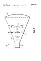
- FIG. 3 shows how the second embodiment of the present invention can be incorporated into a package compatible with known lighting systems.
- VCSELs and methods for manufacturing them are known. See, for example, U.S. Pat. Nos. 5,359,618 and 5,164,949. Forming VCSELs into two-dimensional arrays for data displays is also known. See U.S. Pat. Nos. 5,325,386 and 5,073,041.
- the Sandia National Laboratories demonstrated a VCSEL with a conversion efficiency from electrical power to optical flux of 50% (5 mW of optical power from a 5 mA current and 2 V voltage).
- the Sandia VCSEL used a GaInAs material system, generated light at a wavelength of 980 nm and was roughly 8-10 microns in diameter.
- VCSEL arrays (1 ⁇ 8) of GaAlAs operating at 850 nm have been fabricated.
- the inventor herein has experimented with these arrays by operating the VCSELs in parallel from a single source. Although these arrays operate at only 15-25% conversion efficiency, as compared to Sandia's 50%, they verify the feasibility of operating large arrays of VCSELs in parallel without thermal runaway. Thermal runaway occurred in early power transistors when one emitter finger in the array of emitter fingers used in a single power transistor began to "hog" the current, which increased its operating temperature, which in turn led to even higher current usage, in an accelerating cycle that led to the destruction of the transistor. The inventor herein believes that the series resistance of the Bragg reflectors in each of the VCSELs, undesirable as it is, stabilizes the device and prevents current hogging.
- an optical power source is obtained.
- an array of approximately 10 ⁇ m VCSELs 11, spaced 40 ⁇ m apart center-to-center is fabricated on a 20 ⁇ 20 mil chip 13.
- a 12 ⁇ 12 laser array is easily accommodated.
- a total of 128 lasers allows for a 5 ⁇ 5 mil bonding area 15. If each laser is operated at 2 mA and 2 V, delivering 2 mW of optical flux, then the total input power to the array is 0.5 W and the optical output power is approximately 0.25 W. The remaining 0.25 W must be removed as heat.
- the thermal resistance comprises a spreading term from the 10 ⁇ m circle to the substrate and a linear term of thermal resistance between the lasers and the back surface of the chip. With a heat flow of 0.25 W, the spreading resistance raises the temperature by 1.4° C. and the substrate adds another 2.9° C. for a total chip related temperature rise of 4.3° C. Mounting the chip on a heat spreading substrate, such as chemical vapor deposition ("CVD") grown diamond, AlN or plain copper controls the heat flux without a significant temperature rise.
- CVD chemical vapor deposition
- the VCSELs can also be mounted face down on a heat spreading substrate, which would further reduce the temperature rise within the chip. In this case, the light would be extracted through the substrate.
- the GaAs substrate is transparent. At shorter wavelengths, the substrate would have to be replaced by wafer bonding the structure to a GaP substrate.
- LEDs fabricated from GaAlAs and radiating at 850 nm have a demonstrated internal quantum efficiency of 100%.
- Proper optimization of the VCSEL design in an array similar to that shown in FIG. 1 should result in power conversion efficiencies greater than 50%.
- Such optical power sources would enable IR communication at higher speeds than known IR LEDs permit. They may permit IR LANs and interactive TV. Another possible application is using the arrays for security illumination.
- VCSEL arrays The most significant application for VCSEL arrays is for illumination, using a series of arrays that individually generate light in different parts of the visible light spectrum.
- Sandia National Laboratory has demonstrated red VCSELs fabricated from a GaAlInP material system. These VCSELs generated light at wavelengths from 635-680 nm and at power levels as high as 8 mW for a single VCSEL. The conversion efficiency for the best devices was approximately 15%.
- GaInN devices In the green and blue portions of the visible light spectrum, GaInN devices have demonstrated lasing by optical pumping and green/blue Fabry-Perot lasers have been demonstrated with a ZnSe material system. In the relatively near future, GaInN will be used in Fabry-Perot lasers and in VCSELs.
- the IR VCSEL chip described above can then be scaled to 1 ⁇ 1 mm with the same area density of lasers to provide a monochromatic visible light illumination VCSEL array chip.
- This chip with approximately 500 lasers operating at 2 mA per laser, would have an optical flux of 1 W at 50% conversion efficiency.
- At 560 nm, such a chip would generate a luminous flux of 680 lm.
- At an input current of 1 A and an applied voltage of 2 V, the chip would have a luminous efficiency of 340 lm/W.
- a white light source can be constructed from six VCSEL chips, each chip having an optical flux of 1 W and generating light at equally spaced wavelengths between 475 nm (blue light) and 625 nm (red light).
- Table 1 shows the wavelength/flux relationship for a VCSEL illumination source having six VCSEL arrays and an input of 12 W. This light source with an input of 12 W will generate an optical flux of approximately 2400 lm. Its efficiency is roughly 200 lm/W. A comparison with conventional white light sources of comparable flux levels is shown in Table 2. The 2400 lm flux is equivalent to the flux of a 170 W incandescent light bulb.
- FIG. 2 is a schematic drawing of such a white light illumination source 20 comprised of VCSEL arrays 21 through 26, inclusive.
- the VCSEL arrays each generate a different wavelength of visible light. In a first preferred embodiment, these arrays will generate light at the wavelengths listed in Table 1.
- the VCSEL arrays are in turn coupled to power supply 30 through controller 35.
- power supply 30 must be capable of driving each of the lasers in all of the VCSEL arrays in parallel at the minimum current required for lasing. Controller 35 will permit additional operational flexibility by permitting the user to command more or less light output from the individual arrays and from all of the arrays simultaneously. In so doing, the user can control the color temperature of the source 20, as well as its final light output.
- the described VCSEL array white light illumination source will have many advantages over known lighting sources.
- Table 2 summarizes the efficiency advantages of VCSEL illumination sources over known lighting technologies.
- a VCSEL based light source would offer several other additional advantages over known illumination sources.
- Controller 35 can be used to effect this dimming by reducing the drive current to each of the VCSEL arrays equally and in parallel.
- the dimming range can be further extended if the VCSEL elements of each array have a single common cathode but multiple, independent anodes. This would allow parts of the VCSEL array to be turned on and off independently. Assuming that 10 separate anodes were fabricated for a single array, the dimming range of the array could be extended by an additional factor of 10, in combination with reducing the drive current.
- the color temperature of the light can be changed from bluish cold white to a more yellow, warmer white or any variation or combination in between.
- Source 20 can thus operate over the entire chromaticity diagram.
- a single white light source can also be used as a monochromatic light source of at least six different colors with only a small additional expense. Combined with the dimming ability previously described, the ability to vary color and/or temperature makes the present invention a universal source for decorative or theatrical lighting.
- Fluorescent lamps generate white light by stimulating a phosphor layer with UV light.
- the phosphor layer is a mixture of phosphors generating predominantly three nearly monochromatic lines of light (red, green and blue).
- the VCSEL light source would use six lines of light which improves the color rendering of the illumination source.
- the described white light source has the inherent modulation speed of VCSELs, which can be turned off and on at gigahertz frequencies. This allows the illumination source to be used to distribute signals at gigabits per second rates.
- a low cost, highly asymmetric local area network where high speed signals such as video are broadcast via the light source and low speed signals use conventional telephone wiring can be readily constructed using the present invention.
- a unidirectional signal distribution system in a grocery store, wherein the VCSEL white light illumination source is used both for illumination and signal transmission would permit battery powered electronic shelf labels to be updated through the lighting system without the installation of an IR or RF broadcast system.
- optical receivers are simpler than RF receivers.
- the illumination power levels are very high, permitting the construction of a visible light receiver that would be even simpler than an IR receiver.
- Light sources constructed according to the present invention experience no "turn on” delays, unlike the turn on delay commonly associated with fluorescent light sources. They also have a lifetime measured in tens of thousands of hours, and perhaps as long as ten years.
- the light output from an individual VCSEL is a collimated beam with a dispersion of approximately 10°.
- This beam can be intercepted with low cost optical surfaces to redistribute the flux efficiently to wherever illumination is desired. In case where light spilling is unnecessary or undesirable, this feature translates into another 2x to 5x efficiency improvement when compared with isotropic high temperature conventional light sources.
- VCSELs for illumination does raise the issue of eye safety.
- Light with a temporal coherent wavefront can readily be focused by the eye into a diffraction limited spot on the retina. If the power level in this spot exceeds approximately 200 ⁇ W, permanent damage to the retina can result.
- the VCSEL array has a unique feature that answers the eye safety issue. If the diameter of the individual elements in the VCSEL is increased to 20 to 25 ⁇ m, then the VCSEL no longer lases as one element with temporal coherence. The emitting area breaks into multiple filaments that are not locked into a single coherent mode. If adjacent VCSELs are separated by roughly 20-50 ⁇ m, the array behaves like a number of independent lasers. Temporal coherence is limited to the flux of individual elements, which, in the first preferred embodiment operate at roughly 2 mW each. The temporal coherence of an individual laser element can also be destroyed by intersecting the beam with a holograph-like phase shifting surface. Instead of having to destroy the phase coherence of a 1 W laser, the coherence of many independent 2 mW lasers needs to be destroyed. Thus, the phase coherence must be reduced by a single order of magnitude, as opposed to nearly four orders of magnitude.
- light source 20 of FIG. 2 can be packaged to fit into a known light source package; here, a standard incandescent screw-in light bulb, creating a lighting source 100 that can be easily retro fitted.
- VCSEL arrays 21 through 26 are mounted on ceramic substrate 27 and controlled by controller 35.
- Discrete power supply components 30 are located behind substrate 27 and receive power through socket 28 from a power source.
- Primary beam shaping optics 40 has rear optical surface 41 which destroys the phase coherence of VCSELs 21 through 26 to prevent eye damage and front surface 42 which shapes the light after its phase coherence has been destroyed.
- Secondary beam shaping optics 45 are used to collimate and focus the beam to suit the particular lighting application. By changing secondary beam shaping optics 45, one lighting source can serve in many different applications.
Abstract
Description
              TABLE 1
______________________________________
Wavelength (nm) Flux (lm)
______________________________________
475             77
505             343
535             622
565             665
595             473
625             218
White           2398
______________________________________
              TABLE 2
______________________________________
             Efficiency
Type         (lm/W)   VCSEL Advantage
______________________________________
Incandescent 14       15x
Halogen      20       10x
Fluorescent  80       2.5x
Metal Halide 80       2.5x
Mercury      40        5x
______________________________________
Claims (7)
Priority Applications (9)
| Application Number | Priority Date | Filing Date | Title |
|---|---|---|---|
| US08/548,346 US5707139A (en) | 1995-11-01 | 1995-11-01 | Vertical cavity surface emitting laser arrays for illumination |
| CN96197959A CN1105851C (en) | 1995-11-01 | 1996-10-02 | Vertical cavity surface emitting laser arrays for illumination |
| AU72533/96A AU717622B2 (en) | 1995-11-01 | 1996-10-02 | Vertical cavity surface emitting laser arrays for illumination |
| JP51734097A JP3999268B2 (en) | 1995-11-01 | 1996-10-02 | Vertical cavity surface emitting diode laser array for irradiation |
| PCT/US1996/015822 WO1997016679A1 (en) | 1995-11-01 | 1996-10-02 | Vertical cavity surface emitting laser arrays for illumination |
| KR10-1998-0703254A KR100468256B1 (en) | 1995-11-01 | 1996-10-02 | Vertical cavity surface emitting laser arrays for illumination |
| EP96934011A EP0858573A4 (en) | 1995-11-01 | 1996-10-02 | Vertical cavity surface emitting laser arrays for illumination |
| TW085112567A TW366616B (en) | 1995-11-01 | 1996-10-15 | Vertical cavity surface emitting laser arrays for illumination |
| US08/884,378 US5758951A (en) | 1995-11-01 | 1997-06-27 | Vertical cavity surface emitting laser arrays for illumination |
Applications Claiming Priority (1)
| Application Number | Priority Date | Filing Date | Title |
|---|---|---|---|
| US08/548,346 US5707139A (en) | 1995-11-01 | 1995-11-01 | Vertical cavity surface emitting laser arrays for illumination |
Related Child Applications (1)
| Application Number | Title | Priority Date | Filing Date |
|---|---|---|---|
| US08/884,378 Continuation US5758951A (en) | 1995-11-01 | 1997-06-27 | Vertical cavity surface emitting laser arrays for illumination |
Publications (1)
| Publication Number | Publication Date |
|---|---|
| US5707139A true US5707139A (en) | 1998-01-13 |
Family
ID=24188468
Family Applications (2)
| Application Number | Title | Priority Date | Filing Date |
|---|---|---|---|
| US08/548,346 Expired - Lifetime US5707139A (en) | 1995-11-01 | 1995-11-01 | Vertical cavity surface emitting laser arrays for illumination |
| US08/884,378 Expired - Fee Related US5758951A (en) | 1995-11-01 | 1997-06-27 | Vertical cavity surface emitting laser arrays for illumination |
Family Applications After (1)
| Application Number | Title | Priority Date | Filing Date |
|---|---|---|---|
| US08/884,378 Expired - Fee Related US5758951A (en) | 1995-11-01 | 1997-06-27 | Vertical cavity surface emitting laser arrays for illumination |
Country Status (8)
| Country | Link |
|---|---|
| US (2) | US5707139A (en) |
| EP (1) | EP0858573A4 (en) |
| JP (1) | JP3999268B2 (en) |
| KR (1) | KR100468256B1 (en) |
| CN (1) | CN1105851C (en) |
| AU (1) | AU717622B2 (en) |
| TW (1) | TW366616B (en) |
| WO (1) | WO1997016679A1 (en) |
Cited By (62)
| Publication number | Priority date | Publication date | Assignee | Title |
|---|---|---|---|---|
| US5758951A (en) * | 1995-11-01 | 1998-06-02 | Hewlett-Packard Company | Vertical cavity surface emitting laser arrays for illumination |
| US5837561A (en) * | 1995-11-30 | 1998-11-17 | Hewlett-Packard Company | Fabrication of transparent substrate vertical cavity surface emitting lasers by semiconductor wafer bonding |
| US5986998A (en) * | 1996-10-24 | 1999-11-16 | Samsung Electronics Co., Ltd. | Optical head having two vertical cavity surface emitting lasers with different wavelengths |
| US6200134B1 (en) * | 1998-01-20 | 2001-03-13 | Kerr Corporation | Apparatus and method for curing materials with radiation |
| US20030012246A1 (en) * | 2001-07-12 | 2003-01-16 | Klimek Daniel E. | Semiconductor zigzag laser and optical amplifier |
| US6523979B1 (en) * | 1999-02-09 | 2003-02-25 | Nakanishi, Inc. | Lighting device |
| US6682211B2 (en) * | 2001-09-28 | 2004-01-27 | Osram Sylvania Inc. | Replaceable LED lamp capsule |
| US6711191B1 (en) | 1999-03-04 | 2004-03-23 | Nichia Corporation | Nitride semiconductor laser device |
| US6719446B2 (en) * | 2001-08-24 | 2004-04-13 | Densen Cao | Semiconductor light source for providing visible light to illuminate a physical space |
| US20040090191A1 (en) * | 1997-08-26 | 2004-05-13 | Color Kinetics, Incorporated | Multicolored led lighting method and apparatus |
| US20040105261A1 (en) * | 1997-12-17 | 2004-06-03 | Color Kinetics, Incorporated | Methods and apparatus for generating and modulating illumination conditions |
| US6835956B1 (en) | 1999-02-09 | 2004-12-28 | Nichia Corporation | Nitride semiconductor device and manufacturing method thereof |
| US20050041424A1 (en) * | 1999-11-18 | 2005-02-24 | Color Kinetics, Inc. | Systems and methods for converting illumination |
| US20050040774A1 (en) * | 1999-11-18 | 2005-02-24 | Color Kinetics, Inc. | Methods and apparatus for generating and modulating white light illumination conditions |
| US20050151489A1 (en) * | 1997-08-26 | 2005-07-14 | Color Kinetics Incorporated | Marketplace illumination methods and apparatus |
| US20050231983A1 (en) * | 2002-08-23 | 2005-10-20 | Dahm Jonathan S | Method and apparatus for using light emitting diodes |
| US20050285547A1 (en) * | 1997-08-26 | 2005-12-29 | Color Kinetics Incorporated | Light emitting diode based products |
| US20060203505A1 (en) * | 2002-11-25 | 2006-09-14 | Manfred Griesinger | Wideband illumination device |
| US20060250792A1 (en) * | 2005-05-09 | 2006-11-09 | Gamasonic Ltd. | LED light bulb |
| US20060269897A1 (en) * | 2005-05-27 | 2006-11-30 | Gill Owen J | Curing light instrument |
| US20070020278A1 (en) * | 2004-01-09 | 2007-01-25 | Millennium Pharmaceuticals, Inc.*Ewc* | Diagnosing and treating cancer |
| US20070040503A1 (en) * | 2005-08-18 | 2007-02-22 | Charles Chase | Microstructure non-thermal visible light source |
| US7182597B2 (en) | 2002-08-08 | 2007-02-27 | Kerr Corporation | Curing light instrument |
| US20070241933A1 (en) * | 2004-10-15 | 2007-10-18 | Price Vernon D | Object detection system with a vcsel diode array |
| US7320593B2 (en) | 2000-03-08 | 2008-01-22 | Tir Systems Ltd. | Light emitting diode light source for curing dental composites |
| US20080020235A1 (en) * | 2004-01-15 | 2008-01-24 | Nanosys, Inc. | Nanocrystal doped matrixes |
| US20080062703A1 (en) * | 2001-08-24 | 2008-03-13 | Cao Group, Inc. | Light Bulb Utilizing a Replaceable LED Light Source |
| US7433376B1 (en) | 2006-08-07 | 2008-10-07 | Textron Systems Corporation | Zig-zag laser with improved liquid cooling |
| US20080273329A1 (en) * | 2004-06-15 | 2008-11-06 | Belek Ronald E | High Power Led Electro-Optic Assembly |
| US20090057697A1 (en) * | 2004-10-28 | 2009-03-05 | Henkel Corporation | Led assembly with led-reflector interconnect |
| US20090278165A1 (en) * | 2008-05-09 | 2009-11-12 | National Chiao Tung University | Light emitting device and fabrication method therefor |
| US7645056B1 (en) | 1997-09-25 | 2010-01-12 | Koninklijke Philips Electronics N V | Optical irradiation device having LED and heat pipe |
| US20100096643A1 (en) * | 2001-08-24 | 2010-04-22 | Cao Group, Inc. | Semiconductor light source for illuminating a physical space including a 3-dimensional lead frame |
| US20100187964A1 (en) * | 2008-05-01 | 2010-07-29 | Cao Group, Inc. | LED Lighting Device |
| US20100207502A1 (en) * | 2009-02-17 | 2010-08-19 | Densen Cao | LED Light Bulbs for Space Lighting |
| US20100224905A1 (en) * | 2001-08-24 | 2010-09-09 | Cao Group, Inc. | Semiconductor Light Source |
| US20100279446A1 (en) * | 2005-03-07 | 2010-11-04 | Joseph Reid Henrichs | Optical phase conjugation laser diode |
| US20100276638A1 (en) * | 2009-05-01 | 2010-11-04 | Nanosys, Inc. | Functionalized matrixes for dispersion of nanostructures |
| US20100309656A1 (en) * | 2009-06-09 | 2010-12-09 | O'sullivan Paul | Flashlight with motorized directional lighthead for lightbeam placement |
| US20110037376A1 (en) * | 2008-04-23 | 2011-02-17 | Koninklijke Philips Electronics N.V. | Luminous device |
| US7946912B1 (en) * | 2006-05-01 | 2011-05-24 | Carl J Rennard | Roulette system |
| US20110148328A1 (en) * | 2009-12-19 | 2011-06-23 | Trilumina Corporation | System and method for combining laser arrays for digital outputs |
| US20110234082A1 (en) * | 2001-08-24 | 2011-09-29 | Cao Group, Inc. | Light bulb utilizing a replaceable led light source |
| US8047686B2 (en) | 2006-09-01 | 2011-11-01 | Dahm Jonathan S | Multiple light-emitting element heat pipe assembly |
| US20120296322A1 (en) * | 2010-03-15 | 2012-11-22 | Ya-Man Ltd. | Laser treatment device |
| US8592841B2 (en) | 1997-07-25 | 2013-11-26 | Nichia Corporation | Nitride semiconductor device |
| US8979338B2 (en) | 2009-12-19 | 2015-03-17 | Trilumina Corp. | System for combining laser array outputs into a single beam carrying digital data |
| US8995485B2 (en) | 2009-02-17 | 2015-03-31 | Trilumina Corp. | High brightness pulsed VCSEL sources |
| US8995493B2 (en) | 2009-02-17 | 2015-03-31 | Trilumina Corp. | Microlenses for multibeam arrays of optoelectronic devices for high frequency operation |
| US9005480B2 (en) | 2013-03-14 | 2015-04-14 | Nanosys, Inc. | Method for solventless quantum dot exchange |
| US9066777B2 (en) | 2009-04-02 | 2015-06-30 | Kerr Corporation | Curing light device |
| US9072572B2 (en) | 2009-04-02 | 2015-07-07 | Kerr Corporation | Dental light device |
| US9139770B2 (en) | 2012-06-22 | 2015-09-22 | Nanosys, Inc. | Silicone ligands for stabilizing quantum dot films |
| US9453615B2 (en) * | 2011-01-12 | 2016-09-27 | Linvingstyle Enterprises Limited | Sensing type lighting device with electromagnetic wireless communication module and controlling method thereof |
| WO2016191717A1 (en) * | 2015-05-28 | 2016-12-01 | Vixar | Vcsels and vcsel arrays designed for improved performance as illumination sources and sensors |
| US9726435B2 (en) | 2002-07-25 | 2017-08-08 | Jonathan S. Dahm | Method and apparatus for using light emitting diodes for curing |
| US9876329B2 (en) | 2015-08-03 | 2018-01-23 | Technische Universiteit Eindhoven | One plus one redundant optical interconnects with automated recovery from light source failure |
| US10038304B2 (en) | 2009-02-17 | 2018-07-31 | Trilumina Corp. | Laser arrays for variable optical properties |
| US10244181B2 (en) | 2009-02-17 | 2019-03-26 | Trilumina Corp. | Compact multi-zone infrared laser illuminator |
| US10615871B2 (en) | 2009-02-17 | 2020-04-07 | Trilumina Corp. | High speed free-space optical communications |
| US11095365B2 (en) | 2011-08-26 | 2021-08-17 | Lumentum Operations Llc | Wide-angle illuminator module |
| US11687872B2 (en) | 2017-03-23 | 2023-06-27 | Walmart Apollo, Llc | System and method for remote controlling of electronic shelf labels |
Families Citing this family (34)
| Publication number | Priority date | Publication date | Assignee | Title |
|---|---|---|---|---|
| US5971545A (en) * | 1997-06-25 | 1999-10-26 | Hewlett-Packard Company | Light source for projection display |
| DE69905760T2 (en) | 1998-12-21 | 2004-03-18 | Alliedsignal Inc. | HIGH-PERFORMANCE LAMP WITH INFRARED DIODE |
| US6200002B1 (en) * | 1999-03-26 | 2001-03-13 | Philips Electronics North America Corp. | Luminaire having a reflector for mixing light from a multi-color array of leds |
| EP1168535B1 (en) * | 1999-04-05 | 2006-11-29 | Sharp Kabushiki Kaisha | Semiconductor laser device and its manufacturing method, optical communication system and optical sensor system |
| US6614126B1 (en) * | 2001-10-24 | 2003-09-02 | Rockwell Collins, Inc. | Integrated lighting and data communication apparatus |
| KR20050044865A (en) * | 2002-05-08 | 2005-05-13 | 포세온 테크날러지 인코퍼레이티드 | High efficiency solid-state light source and methods of use and manufacture |
| WO2006072071A2 (en) | 2004-12-30 | 2006-07-06 | Phoseon Technology Inc. | Methods and systems relating to light sources for use in industrial processes |
| JP2004128273A (en) * | 2002-10-03 | 2004-04-22 | Sharp Corp | Light emitting element |
| US6870195B2 (en) * | 2003-02-21 | 2005-03-22 | Agilent Technologies, Inc. | Array of discretely formed optical signal emitters for multi-channel communication |
| US20040179566A1 (en) * | 2003-03-11 | 2004-09-16 | Aharon El-Bahar | Multi-color stacked semiconductor lasers |
| US6827466B2 (en) * | 2003-04-03 | 2004-12-07 | Chih-Cheng Tsai | Color-varying decorative lamp |
| CN101915365B (en) * | 2003-05-05 | 2013-10-30 | 吉尔科有限公司 | LED-based light bulb |
| EP1678442B8 (en) | 2003-10-31 | 2013-06-26 | Phoseon Technology, Inc. | Led light module and manufacturing method |
| US20050276292A1 (en) * | 2004-05-28 | 2005-12-15 | Karl Schrodinger | Circuit arrangement for operating a laser diode |
| EP1684001A1 (en) * | 2005-01-20 | 2006-07-26 | Christian Niederberger | Lighting device |
| CA2620144A1 (en) * | 2005-04-06 | 2006-10-12 | Tir Technology Lp | Lighting module with compact colour mixing and collimating optics |
| WO2007060592A2 (en) * | 2005-11-22 | 2007-05-31 | Koninklijke Philips Electronics N.V. | Light emitting module and manufacturing method |
| WO2008037049A1 (en) * | 2006-09-25 | 2008-04-03 | Tony Mayer | Micro-diffractive surveillance illuminator |
| DE102007041193A1 (en) * | 2007-08-31 | 2009-03-05 | Osram Gesellschaft mit beschränkter Haftung | Light module for a lighting device and lighting device |
| DE102007062047A1 (en) | 2007-12-21 | 2009-07-16 | Osram Opto Semiconductors Gmbh | compact housing |
| JP2008235945A (en) * | 2008-07-03 | 2008-10-02 | Sharp Corp | Light emitting element |
| JP5667177B2 (en) * | 2009-06-16 | 2015-02-12 | コーニンクレッカ フィリップス エヌ ヴェ | Lighting system for spot lighting |
| US8376586B2 (en) * | 2010-03-26 | 2013-02-19 | Robert J. Abbatiello | Low-divergence light pointer apparatus for use through and against transparent surfaces |
| WO2012106678A1 (en) * | 2011-02-03 | 2012-08-09 | Tria Beauty, Inc. | Radiation-based dermatological devices and methods |
| US11406448B2 (en) | 2011-02-03 | 2022-08-09 | Channel Investments, Llc | Devices and methods for radiation-based dermatological treatments |
| US9414888B2 (en) | 2011-02-03 | 2016-08-16 | Tria Beauty, Inc. | Devices and methods for radiation-based dermatological treatments |
| US9789332B2 (en) | 2011-02-03 | 2017-10-17 | Tria Beauty, Inc. | Devices and methods for radiation-based dermatological treatments |
| JP2013030444A (en) * | 2011-07-29 | 2013-02-07 | Sharp Corp | Radiation device, light-emitting device, lighting apparatus, and vehicle headlight |
| RU2632254C2 (en) | 2012-02-22 | 2017-10-03 | Конинклейке Филипс Н.В. | Lighting device |
| JP5611260B2 (en) * | 2012-03-29 | 2014-10-22 | 学校法人立命館 | Lighting device |
| US9456201B2 (en) * | 2014-02-10 | 2016-09-27 | Microsoft Technology Licensing, Llc | VCSEL array for a depth camera |
| AT516729B1 (en) * | 2015-03-25 | 2016-08-15 | Zizala Lichtsysteme Gmbh | Headlights for vehicles |
| US20180301871A1 (en) * | 2017-04-05 | 2018-10-18 | Vixar | Novel patterning of vcsels for displays, sensing, and imaging |
| CN113767249B (en) * | 2019-04-29 | 2023-08-25 | ams传感器亚洲私人有限公司 | lighting device |
Citations (2)
| Publication number | Priority date | Publication date | Assignee | Title |
|---|---|---|---|---|
| US5325386A (en) * | 1992-04-21 | 1994-06-28 | Bandgap Technology Corporation | Vertical-cavity surface emitting laser assay display system |
| US5535230A (en) * | 1994-04-06 | 1996-07-09 | Shogo Tzuzuki | Illuminating light source device using semiconductor laser element |
Family Cites Families (8)
| Publication number | Priority date | Publication date | Assignee | Title |
|---|---|---|---|---|
| US5028802A (en) * | 1990-01-11 | 1991-07-02 | Eye Research Institute Of Retina Foundation | Imaging apparatus and methods utilizing scannable microlaser source |
| US5073041A (en) | 1990-11-13 | 1991-12-17 | Bell Communications Research, Inc. | Integrated assembly comprising vertical cavity surface-emitting laser array with Fresnel microlenses |
| US5164949A (en) | 1991-09-09 | 1992-11-17 | Motorola, Inc. | Vertical cavity surface emitting laser with lateral injection |
| US5266794A (en) * | 1992-01-21 | 1993-11-30 | Bandgap Technology Corporation | Vertical-cavity surface emitting laser optical interconnect technology |
| JP3095545B2 (en) * | 1992-09-29 | 2000-10-03 | 株式会社東芝 | Surface emitting semiconductor light emitting device and method of manufacturing the same |
| GB2277405A (en) * | 1993-04-22 | 1994-10-26 | Sharp Kk | Semiconductor colour display or detector array |
| US5359618A (en) | 1993-06-01 | 1994-10-25 | Motorola, Inc. | High efficiency VCSEL and method of fabrication |
| US5707139A (en) * | 1995-11-01 | 1998-01-13 | Hewlett-Packard Company | Vertical cavity surface emitting laser arrays for illumination |
-
1995
- 1995-11-01 US US08/548,346 patent/US5707139A/en not_active Expired - Lifetime
-
1996
- 1996-10-02 WO PCT/US1996/015822 patent/WO1997016679A1/en not_active Application Discontinuation
- 1996-10-02 KR KR10-1998-0703254A patent/KR100468256B1/en not_active IP Right Cessation
- 1996-10-02 EP EP96934011A patent/EP0858573A4/en not_active Withdrawn
- 1996-10-02 AU AU72533/96A patent/AU717622B2/en not_active Ceased
- 1996-10-02 CN CN96197959A patent/CN1105851C/en not_active Expired - Fee Related
- 1996-10-02 JP JP51734097A patent/JP3999268B2/en not_active Expired - Fee Related
- 1996-10-15 TW TW085112567A patent/TW366616B/en active
-
1997
- 1997-06-27 US US08/884,378 patent/US5758951A/en not_active Expired - Fee Related
Patent Citations (2)
| Publication number | Priority date | Publication date | Assignee | Title |
|---|---|---|---|---|
| US5325386A (en) * | 1992-04-21 | 1994-06-28 | Bandgap Technology Corporation | Vertical-cavity surface emitting laser assay display system |
| US5535230A (en) * | 1994-04-06 | 1996-07-09 | Shogo Tzuzuki | Illuminating light source device using semiconductor laser element |
Cited By (121)
| Publication number | Priority date | Publication date | Assignee | Title |
|---|---|---|---|---|
| US5758951A (en) * | 1995-11-01 | 1998-06-02 | Hewlett-Packard Company | Vertical cavity surface emitting laser arrays for illumination |
| US5837561A (en) * | 1995-11-30 | 1998-11-17 | Hewlett-Packard Company | Fabrication of transparent substrate vertical cavity surface emitting lasers by semiconductor wafer bonding |
| US5986998A (en) * | 1996-10-24 | 1999-11-16 | Samsung Electronics Co., Ltd. | Optical head having two vertical cavity surface emitting lasers with different wavelengths |
| US8592841B2 (en) | 1997-07-25 | 2013-11-26 | Nichia Corporation | Nitride semiconductor device |
| US20050151489A1 (en) * | 1997-08-26 | 2005-07-14 | Color Kinetics Incorporated | Marketplace illumination methods and apparatus |
| US20050285547A1 (en) * | 1997-08-26 | 2005-12-29 | Color Kinetics Incorporated | Light emitting diode based products |
| US20040090191A1 (en) * | 1997-08-26 | 2004-05-13 | Color Kinetics, Incorporated | Multicolored led lighting method and apparatus |
| US20040178751A1 (en) * | 1997-08-26 | 2004-09-16 | Color Kinetics, Incorporated | Multicolored lighting method and apparatus |
| US7161313B2 (en) | 1997-08-26 | 2007-01-09 | Color Kinetics Incorporated | Light emitting diode based products |
| US8096691B2 (en) | 1997-09-25 | 2012-01-17 | Koninklijke Philips Electronics N V | Optical irradiation device |
| US20100073957A1 (en) * | 1997-09-25 | 2010-03-25 | Koninklijke Philips Electronics N V | Optical irradiation device |
| US7645056B1 (en) | 1997-09-25 | 2010-01-12 | Koninklijke Philips Electronics N V | Optical irradiation device having LED and heat pipe |
| US20060152172A9 (en) * | 1997-12-17 | 2006-07-13 | Color Kinetics, Inc. | Methods and apparatus for generating and modulating white light illumination conditions |
| US20060012987A9 (en) * | 1997-12-17 | 2006-01-19 | Color Kinetics, Incorporated | Methods and apparatus for generating and modulating illumination conditions |
| US7387405B2 (en) | 1997-12-17 | 2008-06-17 | Philips Solid-State Lighting Solutions, Inc. | Methods and apparatus for generating prescribed spectrums of light |
| US20040105261A1 (en) * | 1997-12-17 | 2004-06-03 | Color Kinetics, Incorporated | Methods and apparatus for generating and modulating illumination conditions |
| US20060109649A1 (en) * | 1997-12-17 | 2006-05-25 | Color Kinetics Incorporated | Methods and apparatus for controlling a color temperature of lighting conditions |
| US9572643B2 (en) | 1998-01-20 | 2017-02-21 | Kerr Corporation | Apparatus and method for curing materials with radiation |
| US7210930B2 (en) | 1998-01-20 | 2007-05-01 | Kerr Corporation | Apparatus and method for curing materials with radiation |
| US20050003322A1 (en) * | 1998-01-20 | 2005-01-06 | Kerr Corporation | Apparatus and method for curing materials with light radiation |
| US7066733B2 (en) | 1998-01-20 | 2006-06-27 | Kerr Corporation | Apparatus and method for curing materials with light radiation |
| US9622839B2 (en) | 1998-01-20 | 2017-04-18 | Kerr Corporation | Apparatus and method for curing materials with radiation |
| US8568140B2 (en) | 1998-01-20 | 2013-10-29 | Jozef Kovac | Apparatus and method for curing materials with radiation |
| US20040043351A1 (en) * | 1998-01-20 | 2004-03-04 | Kerr Corporation | Apparatus and method for curing materials with radiation |
| US6692251B1 (en) | 1998-01-20 | 2004-02-17 | Kerr Corporation | Apparatus and method for curing materials with light radiation |
| US6200134B1 (en) * | 1998-01-20 | 2001-03-13 | Kerr Corporation | Apparatus and method for curing materials with radiation |
| US6835956B1 (en) | 1999-02-09 | 2004-12-28 | Nichia Corporation | Nitride semiconductor device and manufacturing method thereof |
| US6523979B1 (en) * | 1999-02-09 | 2003-02-25 | Nakanishi, Inc. | Lighting device |
| US20060078022A1 (en) * | 1999-03-04 | 2006-04-13 | Tokuya Kozaki | Nitride semiconductor laser device |
| US20040101986A1 (en) * | 1999-03-04 | 2004-05-27 | Nichia Corporation | Nitride semiconductor laser device |
| US6711191B1 (en) | 1999-03-04 | 2004-03-23 | Nichia Corporation | Nitride semiconductor laser device |
| US8142051B2 (en) | 1999-11-18 | 2012-03-27 | Philips Solid-State Lighting Solutions, Inc. | Systems and methods for converting illumination |
| US20060285325A1 (en) * | 1999-11-18 | 2006-12-21 | Color Kinetics Incorporated | Conventionally-shaped light bulbs employing white leds |
| US20050040774A1 (en) * | 1999-11-18 | 2005-02-24 | Color Kinetics, Inc. | Methods and apparatus for generating and modulating white light illumination conditions |
| US7132785B2 (en) | 1999-11-18 | 2006-11-07 | Color Kinetics Incorporated | Illumination system housing multiple LEDs and provided with corresponding conversion material |
| US20050041424A1 (en) * | 1999-11-18 | 2005-02-24 | Color Kinetics, Inc. | Systems and methods for converting illumination |
| US20070115658A1 (en) * | 1999-11-18 | 2007-05-24 | Color Kinetics Incorporated | Methods and apparatus for generating and modulating white light illumination conditions |
| US20070115665A1 (en) * | 1999-11-18 | 2007-05-24 | Color Kinetics Incorporated | Methods and apparatus for generating and modulating white light illumination conditions |
| US7959320B2 (en) | 1999-11-18 | 2011-06-14 | Philips Solid-State Lighting Solutions, Inc. | Methods and apparatus for generating and modulating white light illumination conditions |
| US7255457B2 (en) * | 1999-11-18 | 2007-08-14 | Color Kinetics Incorporated | Methods and apparatus for generating and modulating illumination conditions |
| US20050030744A1 (en) * | 1999-11-18 | 2005-02-10 | Color Kinetics, Incorporated | Methods and apparatus for generating and modulating illumination conditions |
| US7320593B2 (en) | 2000-03-08 | 2008-01-22 | Tir Systems Ltd. | Light emitting diode light source for curing dental composites |
| US20030012246A1 (en) * | 2001-07-12 | 2003-01-16 | Klimek Daniel E. | Semiconductor zigzag laser and optical amplifier |
| US20100096643A1 (en) * | 2001-08-24 | 2010-04-22 | Cao Group, Inc. | Semiconductor light source for illuminating a physical space including a 3-dimensional lead frame |
| US8569785B2 (en) | 2001-08-24 | 2013-10-29 | Cao Group, Inc. | Semiconductor light source for illuminating a physical space including a 3-dimensional lead frame |
| US20080062703A1 (en) * | 2001-08-24 | 2008-03-13 | Cao Group, Inc. | Light Bulb Utilizing a Replaceable LED Light Source |
| US8723212B2 (en) | 2001-08-24 | 2014-05-13 | Cao Group, Inc. | Semiconductor light source |
| US8882334B2 (en) | 2001-08-24 | 2014-11-11 | Cao Group, Inc. | Light bulb utilizing a replaceable LED light source |
| US20100224905A1 (en) * | 2001-08-24 | 2010-09-09 | Cao Group, Inc. | Semiconductor Light Source |
| US8201985B2 (en) | 2001-08-24 | 2012-06-19 | Cao Group, Inc. | Light bulb utilizing a replaceable LED light source |
| US20110234082A1 (en) * | 2001-08-24 | 2011-09-29 | Cao Group, Inc. | Light bulb utilizing a replaceable led light source |
| US6719446B2 (en) * | 2001-08-24 | 2004-04-13 | Densen Cao | Semiconductor light source for providing visible light to illuminate a physical space |
| US9761775B2 (en) | 2001-08-24 | 2017-09-12 | Epistar Corporation | Semiconductor light source |
| US7976211B2 (en) | 2001-08-24 | 2011-07-12 | Densen Cao | Light bulb utilizing a replaceable LED light source |
| US6682211B2 (en) * | 2001-09-28 | 2004-01-27 | Osram Sylvania Inc. | Replaceable LED lamp capsule |
| US9726435B2 (en) | 2002-07-25 | 2017-08-08 | Jonathan S. Dahm | Method and apparatus for using light emitting diodes for curing |
| US8231383B2 (en) | 2002-08-08 | 2012-07-31 | Kerr Corporation | Curing light instrument |
| US7182597B2 (en) | 2002-08-08 | 2007-02-27 | Kerr Corporation | Curing light instrument |
| US20070134616A1 (en) * | 2002-08-08 | 2007-06-14 | Owen Gill | Curing Light Instrument |
| US20050231983A1 (en) * | 2002-08-23 | 2005-10-20 | Dahm Jonathan S | Method and apparatus for using light emitting diodes |
| US7989839B2 (en) | 2002-08-23 | 2011-08-02 | Koninklijke Philips Electronics, N.V. | Method and apparatus for using light emitting diodes |
| US20060203505A1 (en) * | 2002-11-25 | 2006-09-14 | Manfred Griesinger | Wideband illumination device |
| US20070020278A1 (en) * | 2004-01-09 | 2007-01-25 | Millennium Pharmaceuticals, Inc.*Ewc* | Diagnosing and treating cancer |
| US20080020235A1 (en) * | 2004-01-15 | 2008-01-24 | Nanosys, Inc. | Nanocrystal doped matrixes |
| US20080273329A1 (en) * | 2004-06-15 | 2008-11-06 | Belek Ronald E | High Power Led Electro-Optic Assembly |
| US20070241933A1 (en) * | 2004-10-15 | 2007-10-18 | Price Vernon D | Object detection system with a vcsel diode array |
| US7777173B2 (en) * | 2004-10-15 | 2010-08-17 | Autosense L.L.C. | Object detection system with a VCSEL diode array |
| US20090057697A1 (en) * | 2004-10-28 | 2009-03-05 | Henkel Corporation | Led assembly with led-reflector interconnect |
| US20100279446A1 (en) * | 2005-03-07 | 2010-11-04 | Joseph Reid Henrichs | Optical phase conjugation laser diode |
| US20060250792A1 (en) * | 2005-05-09 | 2006-11-09 | Gamasonic Ltd. | LED light bulb |
| US7347586B2 (en) * | 2005-05-09 | 2008-03-25 | Gamasonic Ltd. | LED light bulb |
| US8113830B2 (en) | 2005-05-27 | 2012-02-14 | Kerr Corporation | Curing light instrument |
| US20060269897A1 (en) * | 2005-05-27 | 2006-11-30 | Gill Owen J | Curing light instrument |
| US20070040503A1 (en) * | 2005-08-18 | 2007-02-22 | Charles Chase | Microstructure non-thermal visible light source |
| US7946912B1 (en) * | 2006-05-01 | 2011-05-24 | Carl J Rennard | Roulette system |
| US7433376B1 (en) | 2006-08-07 | 2008-10-07 | Textron Systems Corporation | Zig-zag laser with improved liquid cooling |
| US8047686B2 (en) | 2006-09-01 | 2011-11-01 | Dahm Jonathan S | Multiple light-emitting element heat pipe assembly |
| US20110037376A1 (en) * | 2008-04-23 | 2011-02-17 | Koninklijke Philips Electronics N.V. | Luminous device |
| US7963667B2 (en) | 2008-05-01 | 2011-06-21 | Stan Thurgood | LED lighting device |
| US20100187964A1 (en) * | 2008-05-01 | 2010-07-29 | Cao Group, Inc. | LED Lighting Device |
| US8465179B2 (en) | 2008-05-01 | 2013-06-18 | Cao Group, Inc. | LED lighting device |
| US7977687B2 (en) | 2008-05-09 | 2011-07-12 | National Chiao Tung University | Light emitter device |
| US20090278165A1 (en) * | 2008-05-09 | 2009-11-12 | National Chiao Tung University | Light emitting device and fabrication method therefor |
| US10938476B2 (en) | 2009-02-17 | 2021-03-02 | Lumentum Operations Llc | System for optical free-space transmission of a string of binary data |
| US11405105B2 (en) | 2009-02-17 | 2022-08-02 | Lumentum Operations Llc | System for optical free-space transmission of a string of binary data |
| US8653723B2 (en) | 2009-02-17 | 2014-02-18 | Cao Group, Inc. | LED light bulbs for space lighting |
| US10038304B2 (en) | 2009-02-17 | 2018-07-31 | Trilumina Corp. | Laser arrays for variable optical properties |
| US10615871B2 (en) | 2009-02-17 | 2020-04-07 | Trilumina Corp. | High speed free-space optical communications |
| US11075695B2 (en) | 2009-02-17 | 2021-07-27 | Lumentum Operations Llc | Eye-safe optical laser system |
| US11121770B2 (en) | 2009-02-17 | 2021-09-14 | Lumentum Operations Llc | Optical laser device |
| US10244181B2 (en) | 2009-02-17 | 2019-03-26 | Trilumina Corp. | Compact multi-zone infrared laser illuminator |
| US8995485B2 (en) | 2009-02-17 | 2015-03-31 | Trilumina Corp. | High brightness pulsed VCSEL sources |
| US8995493B2 (en) | 2009-02-17 | 2015-03-31 | Trilumina Corp. | Microlenses for multibeam arrays of optoelectronic devices for high frequency operation |
| US20100207502A1 (en) * | 2009-02-17 | 2010-08-19 | Densen Cao | LED Light Bulbs for Space Lighting |
| US9066777B2 (en) | 2009-04-02 | 2015-06-30 | Kerr Corporation | Curing light device |
| US9072572B2 (en) | 2009-04-02 | 2015-07-07 | Kerr Corporation | Dental light device |
| US9730778B2 (en) | 2009-04-02 | 2017-08-15 | Kerr Corporation | Curing light device |
| US9693846B2 (en) | 2009-04-02 | 2017-07-04 | Kerr Corporation | Dental light device |
| US9987110B2 (en) | 2009-04-02 | 2018-06-05 | Kerr Corporation | Dental light device |
| US20100276638A1 (en) * | 2009-05-01 | 2010-11-04 | Nanosys, Inc. | Functionalized matrixes for dispersion of nanostructures |
| US8618212B2 (en) | 2009-05-01 | 2013-12-31 | Nanosys, Inc. | Functionalized matrices for dispersion of nanostructures |
| US8283412B2 (en) | 2009-05-01 | 2012-10-09 | Nanosys, Inc. | Functionalized matrices for dispersion of nanostructures |
| US8916064B2 (en) | 2009-05-01 | 2014-12-23 | Nanosys, Inc. | Functionalized matrices for dispersion of nanostructures |
| US20100309656A1 (en) * | 2009-06-09 | 2010-12-09 | O'sullivan Paul | Flashlight with motorized directional lighthead for lightbeam placement |
| US8662700B2 (en) | 2009-06-09 | 2014-03-04 | Paul O'Sullivan | Flashlight with motorized directional lighthead for lightbeam placement |
| US20110148328A1 (en) * | 2009-12-19 | 2011-06-23 | Trilumina Corporation | System and method for combining laser arrays for digital outputs |
| US8979338B2 (en) | 2009-12-19 | 2015-03-17 | Trilumina Corp. | System for combining laser array outputs into a single beam carrying digital data |
| US8613536B2 (en) | 2009-12-19 | 2013-12-24 | Trilumina Corporation | System and method for combining laser arrays for digital outputs |
| US20120296322A1 (en) * | 2010-03-15 | 2012-11-22 | Ya-Man Ltd. | Laser treatment device |
| US9453615B2 (en) * | 2011-01-12 | 2016-09-27 | Linvingstyle Enterprises Limited | Sensing type lighting device with electromagnetic wireless communication module and controlling method thereof |
| US11095365B2 (en) | 2011-08-26 | 2021-08-17 | Lumentum Operations Llc | Wide-angle illuminator module |
| US11451013B2 (en) | 2011-08-26 | 2022-09-20 | Lumentum Operations Llc | Wide-angle illuminator module |
| US9139770B2 (en) | 2012-06-22 | 2015-09-22 | Nanosys, Inc. | Silicone ligands for stabilizing quantum dot films |
| US9005480B2 (en) | 2013-03-14 | 2015-04-14 | Nanosys, Inc. | Method for solventless quantum dot exchange |
| US10177527B2 (en) | 2015-05-28 | 2019-01-08 | Vixar Inc. | VCSELS and VCSEL arrays designed for improved performance as illumination sources and sensors |
| US10749312B2 (en) | 2015-05-28 | 2020-08-18 | Vixar, Inc. | VCSELs and VCSEL arrays designed for improved performance as illumination sources and sensors |
| US10135222B2 (en) | 2015-05-28 | 2018-11-20 | Vixar | VCSELs and VCSEL arrays designed for improved performance as illumination sources and sensors |
| WO2016191717A1 (en) * | 2015-05-28 | 2016-12-01 | Vixar | Vcsels and vcsel arrays designed for improved performance as illumination sources and sensors |
| US11641091B2 (en) | 2015-05-28 | 2023-05-02 | Vixar, Inc. | VCSELs and VCSEL arrays designed for improved performance as illumination sources and sensors |
| US9876329B2 (en) | 2015-08-03 | 2018-01-23 | Technische Universiteit Eindhoven | One plus one redundant optical interconnects with automated recovery from light source failure |
| US11687872B2 (en) | 2017-03-23 | 2023-06-27 | Walmart Apollo, Llc | System and method for remote controlling of electronic shelf labels |
Also Published As
| Publication number | Publication date |
|---|---|
| JP2001520801A (en) | 2001-10-30 |
| CN1200797A (en) | 1998-12-02 |
| EP0858573A4 (en) | 1999-01-20 |
| AU7253396A (en) | 1997-05-22 |
| AU717622B2 (en) | 2000-03-30 |
| CN1105851C (en) | 2003-04-16 |
| US5758951A (en) | 1998-06-02 |
| WO1997016679A1 (en) | 1997-05-09 |
| JP3999268B2 (en) | 2007-10-31 |
| EP0858573A1 (en) | 1998-08-19 |
| TW366616B (en) | 1999-08-11 |
| KR19990067283A (en) | 1999-08-16 |
| KR100468256B1 (en) | 2005-03-16 |
Similar Documents
| Publication | Publication Date | Title |
|---|---|---|
| US5707139A (en) | Vertical cavity surface emitting laser arrays for illumination | |
| US5535230A (en) | Illuminating light source device using semiconductor laser element | |
| US7224001B2 (en) | Semiconductor light source | |
| US6719446B2 (en) | Semiconductor light source for providing visible light to illuminate a physical space | |
| US6465961B1 (en) | Semiconductor light source using a heat sink with a plurality of panels | |
| US6634770B2 (en) | Light source using semiconductor devices mounted on a heat sink | |
| US7497593B2 (en) | Rotational obstruction and beacon signaling apparatus | |
| US9810379B2 (en) | LED lamp | |
| US6746885B2 (en) | Method for making a semiconductor light source | |
| TW594828B (en) | LED lamp | |
| US6799864B2 (en) | High power LED power pack for spot module illumination | |
| US9651239B2 (en) | LED lamp and heat sink | |
| JP5166085B2 (en) | Light emitting diode | |
| US8794793B2 (en) | Solid state lighting device with elongated heatsink | |
| US20100096993A1 (en) | Integrated Modular Lighting Unit | |
| EP3508774A1 (en) | Illumination apparatus | |
| US20070273290A1 (en) | Integrated Modular Light Unit | |
| US20220390074A1 (en) | Led filament and led filament lamp | |
| US20100277059A1 (en) | Light fixture using doped semiconductor nanophosphor in a gas | |
| WO2006056066A1 (en) | Integrated modular lighting unit | |
| US8702275B2 (en) | Light-emitting diode replacement lamp | |
| US9097412B1 (en) | LED lightbulb having a heat sink with a plurality of thermal mounts each having two LED element to emit an even light distribution | |
| Johnson | Leds-an overview of the state of the art in technology and application | |
| US10132486B2 (en) | LED lamp with axial directed reflector | |
| Craford | LEDs a Challenge for Lighting |
Legal Events
| Date | Code | Title | Description |
|---|---|---|---|
| STCF | Information on status: patent grant |
Free format text: PATENTED CASE |
|
| AS | Assignment |
Owner name: HEWLETT-PACKARD COMPANY, A DELAWARE CORPORATION, C Free format text: MERGER;ASSIGNOR:HEWLETT-PACKARD COMPANY, A CALIFORNIA CORPORATION;REEL/FRAME:010841/0649 Effective date: 19980520 |
|
| AS | Assignment |
Owner name: AGILENT TECHNOLOGIES INC, CALIFORNIA Free format text: ASSIGNMENT OF ASSIGNORS INTEREST;ASSIGNOR:HEWLETT-PACKARD COMPANY;REEL/FRAME:010977/0540 Effective date: 19991101 |
|
| FEPP | Fee payment procedure |
Free format text: PAYOR NUMBER ASSIGNED (ORIGINAL EVENT CODE: ASPN); ENTITY STATUS OF PATENT OWNER: LARGE ENTITY |
|
| FPAY | Fee payment |
Year of fee payment: 4 |
|
| FPAY | Fee payment |
Year of fee payment: 8 |
|
| AS | Assignment |
Owner name: AVAGO TECHNOLOGIES GENERAL IP PTE. LTD., SINGAPORE Free format text: ASSIGNMENT OF ASSIGNORS INTEREST;ASSIGNOR:AGILENT TECHNOLOGIES, INC.;REEL/FRAME:017207/0020 Effective date: 20051201 |
|
| AS | Assignment |
Owner name: AVAGO TECHNOLOGIES FIBER IP (SINGAPORE) PTE. LTD., Free format text: ASSIGNMENT OF ASSIGNORS INTEREST;ASSIGNOR:AVAGO TECHNOLOGIES GENERAL IP (SINGAPORE) PTE. LTD.;REEL/FRAME:017675/0199 Effective date: 20060127 |
|
| FPAY | Fee payment |
Year of fee payment: 12 |
|
| AS | Assignment |
Owner name: AVAGO TECHNOLOGIES GENERAL IP (SINGAPORE) PTE. LTD Free format text: MERGER;ASSIGNOR:AVAGO TECHNOLOGIES FIBER IP (SINGAPORE) PTE. LTD.;REEL/FRAME:030369/0672 Effective date: 20121030 |
|
| AS | Assignment |
Owner name: AVAGO TECHNOLOGIES GENERAL IP (SINGAPORE) PTE. LTD Free format text: CORRECTIVE ASSIGNMENT TO CORRECT THE NAME OF THE ASSIGNEE PREVIOUSLY RECORDED ON REEL 017207 FRAME 0020. ASSIGNOR(S) HEREBY CONFIRMS THE ASSIGNMENT;ASSIGNOR:AGILENT TECHNOLOGIES, INC.;REEL/FRAME:038633/0001 Effective date: 20051201 |