US5709060A - Concrete forming system with brace ties - Google Patents
Concrete forming system with brace ties Download PDFInfo
- Publication number
- US5709060A US5709060A US08/413,417 US41341795A US5709060A US 5709060 A US5709060 A US 5709060A US 41341795 A US41341795 A US 41341795A US 5709060 A US5709060 A US 5709060A
- Authority
- US
- United States
- Prior art keywords
- strut
- struts
- truss
- sidewall
- trusses
- Prior art date
- Legal status (The legal status is an assumption and is not a legal conclusion. Google has not performed a legal analysis and makes no representation as to the accuracy of the status listed.)
- Expired - Fee Related
Links
Images


Classifications
-
- E—FIXED CONSTRUCTIONS
- E04—BUILDING
- E04B—GENERAL BUILDING CONSTRUCTIONS; WALLS, e.g. PARTITIONS; ROOFS; FLOORS; CEILINGS; INSULATION OR OTHER PROTECTION OF BUILDINGS
- E04B2/00—Walls, e.g. partitions, for buildings; Wall construction with regard to insulation; Connections specially adapted to walls
- E04B2/02—Walls, e.g. partitions, for buildings; Wall construction with regard to insulation; Connections specially adapted to walls built-up from layers of building elements
- E04B2/42—Walls having cavities between, as well as in, the elements; Walls of elements each consisting of two or more parts, kept in distance by means of spacers, at least one of the parts having cavities
- E04B2/54—Walls having cavities between, as well as in, the elements; Walls of elements each consisting of two or more parts, kept in distance by means of spacers, at least one of the parts having cavities the walls being characterised by fillings in all cavities in order to form a wall construction
-
- E—FIXED CONSTRUCTIONS
- E04—BUILDING
- E04B—GENERAL BUILDING CONSTRUCTIONS; WALLS, e.g. PARTITIONS; ROOFS; FLOORS; CEILINGS; INSULATION OR OTHER PROTECTION OF BUILDINGS
- E04B2/00—Walls, e.g. partitions, for buildings; Wall construction with regard to insulation; Connections specially adapted to walls
- E04B2/84—Walls made by casting, pouring, or tamping in situ
- E04B2/86—Walls made by casting, pouring, or tamping in situ made in permanent forms
- E04B2/8611—Walls made by casting, pouring, or tamping in situ made in permanent forms with spacers being embedded in at least one form leaf
- E04B2/8617—Walls made by casting, pouring, or tamping in situ made in permanent forms with spacers being embedded in at least one form leaf with spacers being embedded in both form leaves
-
- E—FIXED CONSTRUCTIONS
- E04—BUILDING
- E04C—STRUCTURAL ELEMENTS; BUILDING MATERIALS
- E04C1/00—Building elements of block or other shape for the construction of parts of buildings
- E04C1/40—Building elements of block or other shape for the construction of parts of buildings built-up from parts of different materials, e.g. composed of layers of different materials or stones with filling material or with insulating inserts
-
- E—FIXED CONSTRUCTIONS
- E04—BUILDING
- E04B—GENERAL BUILDING CONSTRUCTIONS; WALLS, e.g. PARTITIONS; ROOFS; FLOORS; CEILINGS; INSULATION OR OTHER PROTECTION OF BUILDINGS
- E04B2/00—Walls, e.g. partitions, for buildings; Wall construction with regard to insulation; Connections specially adapted to walls
- E04B2/02—Walls, e.g. partitions, for buildings; Wall construction with regard to insulation; Connections specially adapted to walls built-up from layers of building elements
- E04B2002/0202—Details of connections
- E04B2002/0204—Non-undercut connections, e.g. tongue and groove connections
- E04B2002/0206—Non-undercut connections, e.g. tongue and groove connections of rectangular shape
Definitions
- This invention relates to a concrete forming system and, more particularly, to novel form ties for maintaining the sidewalls of a concrete form in desired longitudinal, vertical and laterally spaced-apart relationships.
- the sidewalls must be immobilized so as to resist pressures on the walls during transport and, more importantly, during concrete pouring and curing. If not, the form sidewalls may shift in lateral and/or vertical and/or longitudinal directions. Such displacements make it difficult to easily connect the forms. Also, the forms may separate along the joints respectively presented along the zones of connection between longitudinally and vertically adjacent forms. If not sufficiently braced the concrete can cause these joints to separate. The industry refers to such separations as "blow outs".
- braces and permanent tension members have been proposed so as to maintain the sidewalls in place to preclude such shifting and/or "blow outs" during concrete pouring and subsequent curing.
- such devices have been relatively complex in construction requiring the sidewalls to have special configurations so as to receive the braces and/or ties.
- Each form tie generally comprises a pair of end trusses with an intermediate web truss spanning the form sidewalls.
- the trusses are formed by a pair of vertical end struts with a pair of horizontal struts spanning the upper and lower ends of the vertical struts.
- a second pair of interior vertical struts and horizontal struts are spaced from the perimetrical struts to form a plurality of secondary rectangular trusses.
- First and second diagonal struts rigidify the trusses.
- the end trusses are embedded in the sidewalls of the forms during the molding process with the intermediate web truss spanning the facing interior surfaces of the sidewalls.
- the ties preclude lateral, vertical and longitudinal shifting of the sidewalls during transport and use.
- the ties utilized adjacent the ends of the form sidewalls are halved so as to not interfere with concrete flow between longitudinally adjacent concrete forms.
- An alternate embodiment of the form tie also comprises a pair of end trusses with an intermediate truss spanning the form sidewalls.
- the exterior vertical end strut of each end truss extends above and below the end truss.
- these end struts are positioned adjacent the exterior surface of each sidewall and cooperate with the smaller interior vertical end strut to reinforce the form sidewall of the concrete form extending between the struts.
- Diagonal struts extend between the upper and lower ends of the exterior vertical struts and interior vertical struts so as to further reinforce the trusses and form sidewalls.
- End ties utilized adjacent the ends of the form sidewalls are approximately one-half the height of the primary tie so as to allow concrete flow between forms.
- a further object of this invention is to provide a concrete form tie, as aforesaid, which is incorporated in the concrete form during the blow molding thereof.
- Another general object of this invention is to provide a concrete form tie, as aforesaid, which resists loads that impart tension, compression, bending, twisting and lateral stresses acting thereon.
- Still a further object of this invention is to provide a concrete form tie, as aforesaid, which diminishes the lateral, vertical and longitudinal displacement of adjacent sidewalls of a concrete form during transport and use.
- a still more particular object of this invention is to provide a concrete form tie, as aforesaid, which presents a plurality of reinforcing trusses within and between the sidewalls of a concrete form.
- a further particular object of this invention is to provide a concrete form tie with trusses, as aforesaid, which are reinforced by diagonal struts extending therethrough.
- Another particular object of this invention is to provide a concrete form tie, as aforesaid, which enhances on-site assembly of the concrete forms.
- a further object of this invention is to provide a concrete form tie, as aforesaid, which does not interfere with concrete flow through the form sidewalls and between adjacent forms.
- Another particular object of this invention is to provide a concrete form tie, as aforesaid, which effectively precludes seepage of the polymeric foam from the form mold during the molding process.
- a further particular object of this invention is to provide a concrete form tie, as aforesaid, which presents a pair of end trusses anchored in each sidewall of a polymeric foam with a web truss defining the lateral distance between the form sidewalls.
- Still a more particular object of this invention is to provide a concrete form tie with end trusses, as aforesaid, the latter having a vertical strut coplanar with the interior surface of a form sidewall to indicate a proper distance between the form sidewalls.
- Another particular object of this invention is to provide a concrete form tie with end trusses, as aforesaid, the latter having a vertical strut anchoring the end truss in a form sidewall.
- FIG. 1 is a perspective view of a plurality of concrete form ties spanning first and second sidewalls of a concrete form.
- FIG. 2 is a perspective view of the form of FIG. 1 with a portion of one sidewall of the form broken away to show the concrete tie embedded within the sidewall of the form.
- FIG. 3 is a plan view of the concrete form tie shown in FIGS. 1 and 2 on an enlarged scale.
- FIG. 4 is a perspective view of the form tie of FIG. 3.
- FIG. 5 is a plan view of an alternative form of the concrete tie for use adjacent the ends of a concrete form.
- FIG. 6 is a perspective view of the concrete tie of FIG. 5.
- FIG. 7 is a section view taken along lines 7--7 in FIG. 9.
- FIG. 8 is an end view of one end of the concrete form of FIG. 9.
- FIG. 9 is a side view of the concrete form with the phantom lines defining the various cavities and form ties therein.
- FIG. 10 is a top view of the concrete form of FIG. 9.
- FIG. 11 is a bottom view of the forms of FIG. 9.
- FIG. 12 is a top view of the tie of FIG. 3.
- FIG. 13 is a top view of the tie of FIG. 5.
- FIG. 14 is a perspective view of an alternative embodiment of a concrete form tie spanning first and second sidewalls of a concrete form with a portion of one sidewall of the form broken away to show an end truss of the tie embedded therein.
- FIG. 15 is an elevation view of the alternative embodiment of a form tie shown in FIG. 14.
- FIG. 16 is a perspective view of the form tie of FIG. 15.
- FIG. 17 is a perspective view of an alternative form of the concrete tie of FIG. 14 for use adjacent the ends of a concrete form.
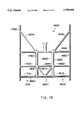
- FIG. 18 is an elevation view of the tie of FIG. 17.
- FIG. 19 is an end view of a concrete form tie of FIG. 14 with the sidewalls of the form removed from one side of the form tie to show the form tie in place.
- FIG. 20 is an end view of a concrete form showing the form tie of FIG. 18 in place.
- FIG. 21 is a diagrammatic top view of a concrete form tie showing the form ties of FIGS. 14 and 17 spanning the sidewalls of the concrete form.
- FIG. 1 shows one type of concrete form 10 as generally comprising a pair of sidewalls 12, 14. Each sidewall has upper 16 and lower 18 longitudinal edges as well as a pair of opposed vertical edges 20, 22.
- the form 10 further includes a pair of longitudinally displaced end walls 24, 26 with intermediate longitudinally spaced-apart partition walls 28.
- the sidewalls 12, 14, end walls 24, 26 and partition walls 28 cooperate to form a plurality of vertical cavities 30 and a vertical slot 32 between the facing surfaces of the end walls 24, 26 and partition walls 28.
- Slot 32 longitudinally spans the length of the form 10 and connects the cavities 30.
- Each form 10 has tongues 34 along the respective upper 16 edges which mate with complementary grooves 36 located along the lower edges of an overlying form 10.
- the forms 10 may be connected in longitudinally extending courses and stacked one atop the other.
- first course of forms are positioned atop a footing and held in place by various materials such as plastic roof cement. It is understood that other types of connection of the first row of forms to the footing may be utilized such as placing the forms in a wet footing and allowing the footing to subsequently dry.
- wet concrete is poured between the form sidewalls 12, 14. (It is understood that the forms are staggered among rows so as to preclude formation of a continuous vertical joint among the form rows.)
- the poured concrete fills the vertical cavities 30 and longitudinally extending vertical slot 32 of each form.
- a horizontal channel is formed which spans the upper and lower forms.
- the poured concrete will fill the channel of the form.
- a concrete wall within slot 32, concrete piers within cavities 30 and a horizontal beam of concrete within the channel is presented.
- the forms 10 are left in place for insulating the resulting concrete wall.
- Wall clips 900 are shown for attaching exterior siding thereto. Such clips 900 are the subject of a separate patent application.
- the courses of the forms may be selectably configured so as to present walls of various configurations.
- door frames, window frames, bucks, bulkheads, and the like may interrupt the courses of forms so as to provide openings for insertion of doors, windows and the like therein while precluding spillage of poured concrete from the forms.
- a hydraulic concrete load acts on the sidewalls 12, 14 of each form 10 as well as on any structure spanning such sidewalls 12, 14.
- the load urges the sidewalls 12, 14 from their proper vertical, lateral and longitudinal spatial relationships.
- the sidewalls 12, 14 may be displaced due to the weight of other forms stacked thereon. In some cases the distance between the sidewalls 12, 14 may vary. Accordingly, problems will arise when attempting to longitudinally and vertically connect forms as the mating lap joint surfaces and/or tongue/groove elements will not be properly aligned.
- each tie 100 presents an overall square configuration.
- the tie comprises first 200 and second 400 laterally spaced-apart end trusses with an intermediate web truss 300 therebetween.
- Each end truss 200, 400 generally comprises a first vertical strut 250, 450 with a second vertical strut 260, 460 laterally displaced therefrom.
- a pair of horizontal struts 620, 660 extend between the lower and upper ends of the end struts 250, 450 and intermediate vertical struts 260, 460. The combination of these horizontal and vertical struts presents the primary rectangular configuration to the end trusses 200, 400 and intermediate web truss 300.
- a second pair of horizontal struts 630, 650 are a second pair of horizontal struts 630, 650. These struts 630, 650 cooperate with the above-described struts to present upper, lower and intermediate trusses within each primary truss 200, 300, 400.
- the respective end trusses 200, 400 thus have lower and upper rectangular trusses 210, 230, 410, 430 with intermediate trusses 220, 420.
- the web truss 300 presents lower and upper trusses 310, 330 with intermediate truss 320.
- a pair of diagonal struts 600, 700 extend between the primary opposed corners of the tie 100 to provide overall rigidity thereto. As seen in FIGS. 3 and 4, the diagonal struts 600, 700 also extend through the lower 210, 410 and upper 230, 430 sections of the end trusses 200, 400 and the central section 320 of the web truss 300.
- Two bipartite molds are used for forming the sidewalls 12, 14 of the polymeric concrete form 10.
- Polystyrene beads are blown into the respective sidewall molds at a first temperature with the beads expanding upon cooling so as to fill the mold.
- a second expansion occurs so that the foam fills the mold.
- the sidewalls are presented.
- the interior vertical struts 260, 460 are configured to seal the mold openings. (Also shown are a plurality of nipples 980 which act as guides to assist the mold operator in aligning the tie 100 within the mold openings.)
- the struts 260, 460 preclude escape of the expanding polystyrene foam from the mold.
- the results of a proper sealing are as shown in FIGS. 1 and 2 as the opposed faces of these struts 260, 460 are not covered by foam.
- the distance between these interior struts 260, 460 define the width of the intermediate web 300 and thus the resulting lateral displacement between the sidewalls 12, 14.
- the coplanar relationship of the opposed, interior faces of the strut 260, 460 with the interior faces of the partition walls 28 present a visual gauge of a common lateral displacement between the sidewalls 12, 14 of all forms. If not, i.e. the strut extends below or beyond the sidewalls, the form 10 sidewalls 12, 14 have an undesirable lateral displacement and should be discarded prior to use.
- the intermediate web 300 fixes and maintains a desired lateral distance between the facing vertical surfaces of the partition sidewalls 28 of the form 10.
- This common lateral modularity assures the builder that the stacked forms 10 will present even exterior surfaces as presented by the exterior surfaces.
- the end trusses 200, 400 are embedded in the sidewalls 12, 14 of the form.
- the end trusses 250, 450 are centrally embedded within the respective sidewall 12, 14 to resist any forces acting thereon which may disrupt the monolithic structure of the sidewall.
- the web 300 spans the sidewalls 12, 14 with the intermediate truss 320 being rigidified by diagonals 600, 700.
- a plurality of trusses 310, 320, 330 extend between the sidewalls so as to maintain the distance therebetween in the presence of hydraulic concrete loads.
- the struts of the trusses are so arranged so as to present a minimal amount of surface to a longitudinal concrete flow through the form 10.
- End ties 600 are as shown in FIGS. 5 and 6 and are approximately one-half the height of the primary tie 100.
- Each end tie 600 comprises first 700 and second 900 end trusses with an intermediate web 800.
- Each end truss 700, 900 comprises a first vertical strut 750, 950 with a second vertical strut 760, 960 laterally displaced therefrom.
- a pair of horizontal struts 830, 860 extend between the lower and upper ends of the end struts 750, 950 and intermediate vertical struts 760, 960.
- An intermediate horizontal strut 840 extends between the vertical struts.
- the struts as above described, present the primary trusses 700, 800, 900.
- Each end truss 700, 900 further presents lower 710, 910 and upper 720, 920 trusses.
- the web 800 also has lower 810 and upper 820 truss sections.
- a diagonal strut 740, 940 extends between the opposed corners of the upper end trusses 720, 920.
- Diagonal struts 870, 880 extend from the upper corners of the lower web truss 810 and towards the midpoint of the lower horizontal strut 860.
- top strut 830 of end tie 600 is aligned with the top strut 660 of a tie 100 at one end of the form 10.
- the bottom strut 620 of tie 600 is aligned with the bottom strut 860 of a tie 100 to present a vertical offset therebetween.
- a pair of form ties 600 will be longitudinally adjacent but vertically offset from one another.
- These vertically offset ties 600 are utilized in lieu of ties 100 to preclude the restriction of concrete flow between longitudinally adjacent forms 10.
- the end ties 600 found at the vertical joint formed by connected forms strengthens this vertical joint so as to diminish "blow out" therealong.
- Such trusses are further reinforced by the diagonal struts extending therethrough. These diagonal struts enhance the maintenance of the overall configuration of the tie, the primary 200, 300, 400 trusses and the secondary trusses therein. Moreover, the portions of the diagonal struts, as embedded in the form material, present additional bearing surfaces resistant to the various pressures presented by the poured concrete. Thus, the vertical, lateral and longitudinal forces acting on the form faces during transport and subsequent use are resisted so as to maintain the desired spatial relationships/modularities of the form sidewalls 12, 14.
- the relatively larger width of the outside 250, 450 struts presents an enlarged bearing surface to the surrounding foam. This relationship not only resists twisting of the form 100 in the face of longitudinal stresses acting thereon but enhances the resistance against pressures resulting from the concrete poured between the form sidewalls 12, 14. Thus, longitudinal shifting of the sidewalls 12, 14 of the form 10 is particularly precluded. Such preclusion also contributes to the elimination of reduction in the width modularity during form use.
- Tie 100 presents a seat 950 extending from the upper horizontal strut 660 for receiving a portion of horizontal rebar (not shown) therein.
- vertical rebar is extended through the respective cavities, offset from the centerline and tied to the horizontal rebar.
- FIGS. 14-21 An alternative tie 1100 for use with the form 10 is shown in FIGS. 14-21.
- This tie 1100 comprises first 1200 and second 1400 laterally spaced-apart end trusses with an intermediate truss 1300 therebetween.
- Each end truss 1200, 1400 generally comprises a first vertical exterior strut 1250, 1450 with a second vertical interior strut 1260, 1460 laterally displaced therefrom.
- a pair of horizontal struts 1620, 1660 extend between the end struts 1250, 1450 and ends of the vertical interior struts 1260, 1460. The combination of these horizontal and vertical struts presents the primary configuration to the end trusses 1200, 1400 and intermediate truss 1300.
- a second pair of horizontal struts 1630, 1650 are a second pair of horizontal struts 1630, 1650. These struts 1630, 1650 cooperate with the above-described struts of tie 100 to present upper, lower and intermediate trusses within each primary truss 1200, 1300, 1400.
- the respective end trusses 1200, 1400 thus have lower and upper rectangular trusses 1210, 1230, 1410, 1430 with intermediate trusses 1220, 1420.
- the intermediate truss 1300 presents lower and upper trusses 1310, 1330 with intermediate truss 1320.
- a pair of upper and lower diagonal struts 1600, 1610, 1700, 1710 extend between upper and lower ends of exterior struts 1250, 1450 and a corner of the upper trusses 1230, 1430 and lower trusses 1210, 1410 to provide reinforcement between the interior struts 1260, 1460 and exterior struts 1250, 1450 as well as the respective trusses 1200, 1400.
- a diagonal strut 1612 also extends through the middle truss 1320 of the intermediate truss 1300.
- two bipartite molds are used for forming the sidewalls 12, 14 of the polymeric concrete form 10.
- Polystyrene beads are blown into the respective sidewall molds at a first temperature with the beads expanding upon cooling so as to fill the mold.
- a second expansion occurs so that the foam fills the mold.
- the sidewalls are presented.
- the interior vertical struts 1260, 1460 are configured to seal the mold openings which allow the end trusses 1200, 1400 to extend into the molds.
- the exterior struts 1250, 1450 seal openings on the outside of the mold.
- a plurality of nipples 1980 act as guides to assist the mold operator in aligning the tie 1100 within the mold openings.
- the struts 1250, 1260, 1450, 1460 preclude escape of the expanding polystyrene foam from the mold. The results of a proper sealing are as shown in FIG. 14 as the opposed faces of these struts 1260, 1460 are not covered by foam.
- the exterior faces of struts 1250, 1450 are generally flush with the exterior surfaces of the respective sidewalls 12, 14.
- the distance between these interior struts 1260, 1460 define the width of the intermediate web 1300 and thus the resulting lateral displacement between the interior surfaces of the sidewalls 12, 14. Accordingly, the width of the resulting concrete pier within cavity 30 is likewise predetermined.
- the coplanar relationship of the struts 1250, 1260, 1450, 1460 with the exterior and interior faces of the sidewalls present a visual gauge of a common lateral displacement between the sidewalls 12, 14 of all forms. If not, i.e. the struts extend below or beyond the sidewalls, the form 10 sidewalls 12, 14 have an undesirable lateral displacement and should be discarded prior to use.
- the intermediate truss 1300 fixes and maintains a desired lateral distance between the facing vertical surfaces of the partition sidewalls 28 of the form 10. This common lateral modularity also assures the builder that the stacked forms 10 will present even exterior surfaces as presented by the exterior surfaces of the sidewalls.
- the end trusses 1200, 1400 span the lateral extent of the sidewalls 12, 14 of the form 10 as the end struts 1250, 1450, 1260, 1460 are coplanar with the exterior and interior faces of the sidewalls 12, 14.
- This strut/sidewall relationship effectively resists any forces acting on the sidewalls 12, 14 which may disrupt the monolithic structure and spatial relationship of the form sidewalls. Stress forces acting throughout the sidewalls are resisted by the outside struts 1250, 1450 as positioned relative to the sidewall 12, 14.
- diagonal struts 1600, 1610, 1700, 1710 further rigidify the end trusses 1200, 1400 so as to resist any twisting, turning, bending, etc of the trusses and struts therein due to forces acting on the form sidewalls 12, 14.
- End ties 1600 are as shown in FIGS. 17 and 18.
- Each end tie 1600 comprises first 1700 and second 1900 end trusses with an intermediate truss 1800.
- Each end truss 1700, 1900 comprises a first elongated vertical strut 1750, 1950 relative to a second smaller vertical strut 1760, 1960 laterally displaced therefrom.
- a horizontal strut 1830 extends between the end struts 1750, 1950 and intermediate vertical struts 1760, 1960.
- a lower horizontal strut 1860 extends between these struts at the lower end thereof.
- An intermediate horizontal strut 1840 extends between these vertical struts.
- each strut 1750, 1950 and towards a corner of the intersection of struts 1760, 1960 and horizontal strut 1830 are diagonal struts 1804, 1806.
- the struts as above described, present the primary trusses 1700, 1800, 1900.
- Each end truss 1700, 1900 further presents lower 1710, 1910 and upper 1720, 1920 trusses.
- the web 1800 also has lower 1810 and upper 1820 truss sections with the lower truss 1810 having a V-shaped diagonal 1812 therein.
- the truss arrangement of tie 1600 is generally one-half the dimension of the truss arrangement of tie 1100 except for the exterior vertical struts 1950, 1960.
- the end tie 1600 at one end of the form is positioned such that the top strut 1830 of end tie 1600 is generally aligned with the top strut 1660 of an adjacent tie 1100.
- the bottom strut 1860 of tie 1600 is generally aligned with the bottom strut 1620 of an adjacent tie 1100.
- Such trusses are reinforced by the position of the exterior struts 1250, 1450, 1750, 1950 as well as the diagonal struts 1600, 1610, 1700, 1710, 1804, 1806. These diagonal struts enhance the maintenance of the overall configuration of the ties 1100, 1600, as well as the primary and the secondary trusses therein. Moreover, the diagonal struts of each tie 1100, 1600 as embedded in the form material, present additional bearing surfaces which resist the various forces acting on the form. Thus, the vertical, lateral and longitudinal forces acting on the form faces during transport and subsequent use are resisted so as to maintain the desired spatial relationships/modularities of the form sidewalls 12, 14.
- the relatively larger width of the outside 1250, 1450, 1750, 1950 struts presents an enlarged bearing surface to the surrounding foam.
- This coplanar relationship with the sidewall surface not only enhances the resistance to twisting of the form 10 in the face of stresses acting thereon but also enhances the resistance against pressures resulting from concrete being poured between the form sidewalls 12, 14. Thus, shifting of the sidewalls 12, 14 of the form 10 is precluded.
- Tie 1100 also presents a seat 1950 extending from the upper horizontal strut 660 for receiving a portion of horizontal rebar (not shown) therein. Upon rebar placement vertical rebar is extended through the respective cavities, offset from the centerline and tied to the horizontal rebar.
Abstract
Description
Claims (11)
Priority Applications (1)
| Application Number | Priority Date | Filing Date | Title |
|---|---|---|---|
| US08/413,417 US5709060A (en) | 1994-11-04 | 1995-03-30 | Concrete forming system with brace ties |
Applications Claiming Priority (2)
| Application Number | Priority Date | Filing Date | Title |
|---|---|---|---|
| US33414694A | 1994-11-04 | 1994-11-04 | |
| US08/413,417 US5709060A (en) | 1994-11-04 | 1995-03-30 | Concrete forming system with brace ties |
Related Parent Applications (1)
| Application Number | Title | Priority Date | Filing Date |
|---|---|---|---|
| US33414694A Continuation-In-Part | 1994-11-04 | 1994-11-04 |
Publications (1)
| Publication Number | Publication Date |
|---|---|
| US5709060A true US5709060A (en) | 1998-01-20 |
Family
ID=46202597
Family Applications (1)
| Application Number | Title | Priority Date | Filing Date |
|---|---|---|---|
| US08/413,417 Expired - Fee Related US5709060A (en) | 1994-11-04 | 1995-03-30 | Concrete forming system with brace ties |
Country Status (1)
| Country | Link |
|---|---|
| US (1) | US5709060A (en) |
Cited By (55)
| Publication number | Priority date | Publication date | Assignee | Title |
|---|---|---|---|---|
| WO1998040577A1 (en) * | 1997-03-11 | 1998-09-17 | Cymbala Patrick M | Insulating concrete form system |
| WO1999015738A1 (en) * | 1997-09-25 | 1999-04-01 | Jorge Pardo | Interlocking blocks of precise height |
| EP1002911A2 (en) * | 1998-11-20 | 2000-05-24 | Robert A. Cantarano | Modular concrete building system |
| US6088985A (en) * | 1998-12-24 | 2000-07-18 | Delta-Tie, Inc. | Structural tie shear connector for concrete and insulation sandwich walls |
| US6324804B1 (en) | 1999-01-15 | 2001-12-04 | Plasti—FAB (division of PFB Corporation) | Concrete wall forming system |
| US6378260B1 (en) | 2000-07-12 | 2002-04-30 | Phoenix Systems & Components, Inc. | Concrete forming system with brace ties |
| US20030029106A1 (en) * | 1999-03-30 | 2003-02-13 | Arxx Building Products, Inc. | Bridging member for concrete form walls |
| US20030033782A1 (en) * | 2001-08-20 | 2003-02-20 | Schmidt Donald L. | Form bracing tie bracket for modular insulating concrete form system and form using the same |
| US20030033781A1 (en) * | 2001-08-20 | 2003-02-20 | Schmidt Donald L. | Modified flat wall modular insulated concrete form system |
| US20030208987A1 (en) * | 2002-05-08 | 2003-11-13 | Dayton Superior Corporation | Structural tie shear connector for concrete and insulation composite panels |
| US6647686B2 (en) | 2001-03-09 | 2003-11-18 | Daniel D. Dunn | System for constructing insulated concrete structures |
| US6668503B2 (en) | 1999-04-16 | 2003-12-30 | Polyform A.G.P. Inc. | Concrete wall form and connectors therefor |
| US20040045238A1 (en) * | 2001-03-09 | 2004-03-11 | Dunn Daniel D. | Reinforced composite system for constructing insulated concrete structures |
| US20040045237A1 (en) * | 2002-09-05 | 2004-03-11 | American Polysteel, Llc | Insulated concrete form and welded wire form tie |
| US20040159061A1 (en) * | 2001-08-20 | 2004-08-19 | Schmidt Donald L. | Insulated concrete form system and method for use |
| US6820384B1 (en) | 2000-10-19 | 2004-11-23 | Reward Wall Systems, Inc. | Prefabricated foam block concrete forms and ties molded therein |
| US20050028467A1 (en) * | 1997-07-04 | 2005-02-10 | Bentley Frank B. | Tie assembly for a wall form system |
| US20050204679A1 (en) * | 2004-03-16 | 2005-09-22 | Tritex Icf Products, Inc. | Prefabricated foam block concrete forms with open tooth connection means |
| US6978581B1 (en) * | 1997-02-04 | 2005-12-27 | Pentstar Corporation | Composite building block with connective structure |
| US7007436B1 (en) * | 2005-01-12 | 2006-03-07 | Kelley Jay R | Snap-in-place building block |
| US20060201090A1 (en) * | 2005-02-25 | 2006-09-14 | Tricia Guevara | Lightweight compositions and articles containing such |
| US20060251851A1 (en) * | 2005-02-25 | 2006-11-09 | Jay Bowman | Composite pre-formed construction articles |
| US20070022708A1 (en) * | 2003-05-21 | 2007-02-01 | Graham Glasspool | Building block |
| US20070113505A1 (en) * | 2005-11-18 | 2007-05-24 | Polyform A.G.P. Inc. | Stackable construction panel intersection assembly |
| US20070294970A1 (en) * | 2006-06-14 | 2007-12-27 | Dale Marshall | Insulated concrete form |
| US20080066408A1 (en) * | 2006-09-14 | 2008-03-20 | Blain Hileman | Insulated concrete form |
| US20080107852A1 (en) * | 2006-11-08 | 2008-05-08 | Rubb Justin D | Foamed plastic structures |
| US20080104911A1 (en) * | 2006-11-08 | 2008-05-08 | Jarvie Shawn P | Insulated concrete form |
| US20080104912A1 (en) * | 2006-11-08 | 2008-05-08 | Ginawati Au | Insulated concrete form |
| US20080250739A1 (en) * | 2006-11-08 | 2008-10-16 | Nova Chemicals Inc. | Foamed plastic structures |
| WO2009049336A1 (en) * | 2007-10-15 | 2009-04-23 | Ggb Gmbh | Spacer and structural component for producing a wall construction, and method and device |
| US20090120027A1 (en) * | 2007-11-08 | 2009-05-14 | Victor Amend | Concrete form tie with connector for finishing panel |
| US20090202307A1 (en) * | 2008-02-11 | 2009-08-13 | Nova Chemicals Inc. | Method of constructing an insulated shallow pier foundation building |
| US20090313914A1 (en) * | 2008-06-20 | 2009-12-24 | Nova Chemicals, Inc.. | Footer cleat for insulating concrete form |
| US20100037545A1 (en) * | 2005-11-15 | 2010-02-18 | Milan Kekanovic | The possibility of special lightening, insulating and reinforcing intermediate floor constructions |
| US20100088984A1 (en) * | 2005-02-25 | 2010-04-15 | Nova Chemicals Inc. | Lightweight compositions and articles containing such |
| WO2010047919A1 (en) * | 2008-10-20 | 2010-04-29 | Nova Chemicals Inc. | Locking tie and insulating concrete form |
| US7861479B2 (en) | 2005-01-14 | 2011-01-04 | Airlite Plastics, Co. | Insulated foam panel forms |
| US8048219B2 (en) | 2007-09-20 | 2011-11-01 | Nova Chemicals Inc. | Method of placing concrete |
| USRE43253E1 (en) | 2005-03-22 | 2012-03-20 | Nova Chemicals Inc. | Lightweight concrete compositions |
| USD713975S1 (en) | 2012-07-30 | 2014-09-23 | Airlite Plastics Co. | Insulative insert for insulated concrete form |
| US8887465B2 (en) | 2012-01-13 | 2014-11-18 | Airlite Plastics Co. | Apparatus and method for construction of structures utilizing insulated concrete forms |
| US8919067B2 (en) | 2011-10-31 | 2014-12-30 | Airlite Plastics Co. | Apparatus and method for construction of structures utilizing insulated concrete forms |
| US20150033660A1 (en) * | 2012-10-04 | 2015-02-05 | Joe Balducci, JR. | Interlocking masonry unit |
| US20150218806A1 (en) * | 2013-02-04 | 2015-08-06 | Andre Cossette | Crossed ties for construction block assembly |
| US9151051B2 (en) | 2013-02-04 | 2015-10-06 | Andre Cossette | 65 db sound barrier insulated block |
| CN106840925A (en) * | 2017-03-31 | 2017-06-13 | 沈阳建筑大学 | Research structure rod member bends and turns round the experimental rig and method of Hysteresis Behavior |
| US20180044915A1 (en) * | 2007-02-02 | 2018-02-15 | Les Materiaux De Construction Oldcastle Canada, Inc. | Wall with decorative facing |
| US10273647B2 (en) | 2010-09-28 | 2019-04-30 | Les Materiaux De Construction Oldcastle Canada, Inc. | Retaining wall |
| US10753109B2 (en) | 2018-08-22 | 2020-08-25 | Victor Amend | Concrete form tie, and concrete formwork comprising same |
| US10787827B2 (en) | 2016-11-14 | 2020-09-29 | Airlite Plastics Co. | Concrete form with removable sidewall |
| US11008752B1 (en) * | 2020-10-05 | 2021-05-18 | Juan Diego Castro | Insulating superblocks for constructing modular superblock assemblies |
| US11155995B2 (en) | 2018-11-19 | 2021-10-26 | Airlite Plastics Co. | Concrete form with removable sidewall |
| US11352787B2 (en) * | 2019-06-18 | 2022-06-07 | Victor Amend | Concrete form panel, and concrete formwork comprising same |
| US20230407636A1 (en) * | 2022-06-16 | 2023-12-21 | ICF Building Systems LLC | Concrete form systems, devices, and related methods |
Citations (20)
| Publication number | Priority date | Publication date | Assignee | Title |
|---|---|---|---|---|
| US880820A (en) * | 1905-12-08 | 1908-03-03 | Arthur Samuel Pierson | Reinforcing and tension device for concrete structures. |
| US1871318A (en) * | 1929-01-30 | 1932-08-09 | Richard F Greenwood | Precast concrete structural unit |
| US3778020A (en) * | 1972-03-09 | 1973-12-11 | C Burrows | Foundation strip for concrete molding |
| US3788020A (en) * | 1966-03-22 | 1974-01-29 | Roher Bohm Ltd | Foamed plastic concrete form with fire resistant tension member |
| US3872636A (en) * | 1973-05-07 | 1975-03-25 | Pacenti Robert A | Light weight load bearing metal structural panel |
| US3922828A (en) * | 1973-11-15 | 1975-12-02 | Tri International Corp | Structural member |
| US3979867A (en) * | 1975-06-20 | 1976-09-14 | National Gypsum Company | Nailable foam faced board |
| US4223501A (en) * | 1978-12-29 | 1980-09-23 | Rocky Mountain Foam Form, Inc. | Concrete form |
| US4516372A (en) * | 1981-08-14 | 1985-05-14 | Grutsch George A | Concrete formwork |
| US4698947A (en) * | 1986-11-13 | 1987-10-13 | Mckay Harry | Concrete wall form tie system |
| US4706429A (en) * | 1985-11-20 | 1987-11-17 | Young Rubber Company | Permanent non-removable insulating type concrete wall forming structure |
| US4730422A (en) * | 1985-11-20 | 1988-03-15 | Young Rubber Company | Insulating non-removable type concrete wall forming structure and device and system for attaching wall coverings thereto |
| US4731968A (en) * | 1982-04-23 | 1988-03-22 | Daniele Obino | Concrete formwork component |
| US4750308A (en) * | 1987-02-09 | 1988-06-14 | Mckay Harry | Heat resistant, insulated wall construction |
| US4765109A (en) * | 1987-09-25 | 1988-08-23 | Boeshart Patrick E | Adjustable tie |
| US4879855A (en) * | 1988-04-20 | 1989-11-14 | Berrenberg John L | Attachment and reinforcement member for molded construction forms |
| US4884382A (en) * | 1988-05-18 | 1989-12-05 | Horobin David D | Modular building-block form |
| US4889310A (en) * | 1988-05-26 | 1989-12-26 | Boeshart Patrick E | Concrete forming system |
| US4916879A (en) * | 1989-09-18 | 1990-04-17 | Boeshart Patrick E | Corner tie |
| US5065561A (en) * | 1988-10-19 | 1991-11-19 | American Construction Products, Inc. | Form work system |
-
1995
- 1995-03-30 US US08/413,417 patent/US5709060A/en not_active Expired - Fee Related
Patent Citations (21)
| Publication number | Priority date | Publication date | Assignee | Title |
|---|---|---|---|---|
| US880820A (en) * | 1905-12-08 | 1908-03-03 | Arthur Samuel Pierson | Reinforcing and tension device for concrete structures. |
| US1871318A (en) * | 1929-01-30 | 1932-08-09 | Richard F Greenwood | Precast concrete structural unit |
| US3788020A (en) * | 1966-03-22 | 1974-01-29 | Roher Bohm Ltd | Foamed plastic concrete form with fire resistant tension member |
| US3778020A (en) * | 1972-03-09 | 1973-12-11 | C Burrows | Foundation strip for concrete molding |
| US3872636A (en) * | 1973-05-07 | 1975-03-25 | Pacenti Robert A | Light weight load bearing metal structural panel |
| US3922828A (en) * | 1973-11-15 | 1975-12-02 | Tri International Corp | Structural member |
| US3979867A (en) * | 1975-06-20 | 1976-09-14 | National Gypsum Company | Nailable foam faced board |
| US4223501A (en) * | 1978-12-29 | 1980-09-23 | Rocky Mountain Foam Form, Inc. | Concrete form |
| US4516372A (en) * | 1981-08-14 | 1985-05-14 | Grutsch George A | Concrete formwork |
| US4516372B1 (en) * | 1981-08-14 | 2000-04-25 | Ciu Corp | Concrete formwork |
| US4731968A (en) * | 1982-04-23 | 1988-03-22 | Daniele Obino | Concrete formwork component |
| US4706429A (en) * | 1985-11-20 | 1987-11-17 | Young Rubber Company | Permanent non-removable insulating type concrete wall forming structure |
| US4730422A (en) * | 1985-11-20 | 1988-03-15 | Young Rubber Company | Insulating non-removable type concrete wall forming structure and device and system for attaching wall coverings thereto |
| US4698947A (en) * | 1986-11-13 | 1987-10-13 | Mckay Harry | Concrete wall form tie system |
| US4750308A (en) * | 1987-02-09 | 1988-06-14 | Mckay Harry | Heat resistant, insulated wall construction |
| US4765109A (en) * | 1987-09-25 | 1988-08-23 | Boeshart Patrick E | Adjustable tie |
| US4879855A (en) * | 1988-04-20 | 1989-11-14 | Berrenberg John L | Attachment and reinforcement member for molded construction forms |
| US4884382A (en) * | 1988-05-18 | 1989-12-05 | Horobin David D | Modular building-block form |
| US4889310A (en) * | 1988-05-26 | 1989-12-26 | Boeshart Patrick E | Concrete forming system |
| US5065561A (en) * | 1988-10-19 | 1991-11-19 | American Construction Products, Inc. | Form work system |
| US4916879A (en) * | 1989-09-18 | 1990-04-17 | Boeshart Patrick E | Corner tie |
Cited By (81)
| Publication number | Priority date | Publication date | Assignee | Title |
|---|---|---|---|---|
| US6978581B1 (en) * | 1997-02-04 | 2005-12-27 | Pentstar Corporation | Composite building block with connective structure |
| US5896714A (en) * | 1997-03-11 | 1999-04-27 | Cymbala; Patrick M. | Insulating concrete form system |
| WO1998040577A1 (en) * | 1997-03-11 | 1998-09-17 | Cymbala Patrick M | Insulating concrete form system |
| US20050028467A1 (en) * | 1997-07-04 | 2005-02-10 | Bentley Frank B. | Tie assembly for a wall form system |
| WO1999015738A1 (en) * | 1997-09-25 | 1999-04-01 | Jorge Pardo | Interlocking blocks of precise height |
| US6145267A (en) * | 1997-09-25 | 2000-11-14 | Pardo; Jorge | Interlocking blocks of precise height |
| EP1002911A2 (en) * | 1998-11-20 | 2000-05-24 | Robert A. Cantarano | Modular concrete building system |
| EP1002911A3 (en) * | 1998-11-20 | 2001-10-17 | Robert A. Cantarano | Modular concrete building system |
| US6088985A (en) * | 1998-12-24 | 2000-07-18 | Delta-Tie, Inc. | Structural tie shear connector for concrete and insulation sandwich walls |
| US6324804B1 (en) | 1999-01-15 | 2001-12-04 | Plasti—FAB (division of PFB Corporation) | Concrete wall forming system |
| US20030029106A1 (en) * | 1999-03-30 | 2003-02-13 | Arxx Building Products, Inc. | Bridging member for concrete form walls |
| US7032357B2 (en) | 1999-03-30 | 2006-04-25 | Arxx Building Products, Inc. | Bridging member for concrete form walls |
| US6668503B2 (en) | 1999-04-16 | 2003-12-30 | Polyform A.G.P. Inc. | Concrete wall form and connectors therefor |
| US6378260B1 (en) | 2000-07-12 | 2002-04-30 | Phoenix Systems & Components, Inc. | Concrete forming system with brace ties |
| US6820384B1 (en) | 2000-10-19 | 2004-11-23 | Reward Wall Systems, Inc. | Prefabricated foam block concrete forms and ties molded therein |
| US6935081B2 (en) | 2001-03-09 | 2005-08-30 | Daniel D. Dunn | Reinforced composite system for constructing insulated concrete structures |
| US20040045238A1 (en) * | 2001-03-09 | 2004-03-11 | Dunn Daniel D. | Reinforced composite system for constructing insulated concrete structures |
| US6647686B2 (en) | 2001-03-09 | 2003-11-18 | Daniel D. Dunn | System for constructing insulated concrete structures |
| US20030033782A1 (en) * | 2001-08-20 | 2003-02-20 | Schmidt Donald L. | Form bracing tie bracket for modular insulating concrete form system and form using the same |
| US20040159061A1 (en) * | 2001-08-20 | 2004-08-19 | Schmidt Donald L. | Insulated concrete form system and method for use |
| US20030033781A1 (en) * | 2001-08-20 | 2003-02-20 | Schmidt Donald L. | Modified flat wall modular insulated concrete form system |
| US6922962B2 (en) * | 2001-08-20 | 2005-08-02 | Donald L. Schmidt | Modified flat wall modular insulated concrete form system |
| US6761007B2 (en) * | 2002-05-08 | 2004-07-13 | Dayton Superior Corporation | Structural tie shear connector for concrete and insulation composite panels |
| US20030208987A1 (en) * | 2002-05-08 | 2003-11-13 | Dayton Superior Corporation | Structural tie shear connector for concrete and insulation composite panels |
| US20040045237A1 (en) * | 2002-09-05 | 2004-03-11 | American Polysteel, Llc | Insulated concrete form and welded wire form tie |
| US7415804B2 (en) * | 2002-09-05 | 2008-08-26 | Coombs Jerry D | Isulated concrete form having welded wire form tie |
| US20070022708A1 (en) * | 2003-05-21 | 2007-02-01 | Graham Glasspool | Building block |
| US20050204679A1 (en) * | 2004-03-16 | 2005-09-22 | Tritex Icf Products, Inc. | Prefabricated foam block concrete forms with open tooth connection means |
| US7409801B2 (en) | 2004-03-16 | 2008-08-12 | Tritex Icf Products, Inc. | Prefabricated foam block concrete forms with open tooth connection means |
| US7007436B1 (en) * | 2005-01-12 | 2006-03-07 | Kelley Jay R | Snap-in-place building block |
| US7861479B2 (en) | 2005-01-14 | 2011-01-04 | Airlite Plastics, Co. | Insulated foam panel forms |
| US20060201090A1 (en) * | 2005-02-25 | 2006-09-14 | Tricia Guevara | Lightweight compositions and articles containing such |
| US7666258B2 (en) | 2005-02-25 | 2010-02-23 | Nova Chemicals Inc. | Lightweight compositions and articles containing such |
| US7963080B1 (en) | 2005-02-25 | 2011-06-21 | Nova Chemicals Inc. | Composite pre-formed construction articles |
| US7964272B2 (en) | 2005-02-25 | 2011-06-21 | Nova Chemicals Inc. | Lightweight compositions and articles containing such |
| US20110138725A1 (en) * | 2005-02-25 | 2011-06-16 | Nova Chemicals Inc. | Composite pre-formed construction articles |
| US7790302B2 (en) | 2005-02-25 | 2010-09-07 | Nova Chemicals Inc. | Lightweight compositions and articles containing such |
| US20060251851A1 (en) * | 2005-02-25 | 2006-11-09 | Jay Bowman | Composite pre-formed construction articles |
| US8752348B2 (en) | 2005-02-25 | 2014-06-17 | Syntheon Inc. | Composite pre-formed construction articles |
| US20100088984A1 (en) * | 2005-02-25 | 2010-04-15 | Nova Chemicals Inc. | Lightweight compositions and articles containing such |
| USRE43253E1 (en) | 2005-03-22 | 2012-03-20 | Nova Chemicals Inc. | Lightweight concrete compositions |
| US8122660B2 (en) * | 2005-11-15 | 2012-02-28 | Milan Kekanovic | Possibility of special lightening, insulating and reinforcing intermediate floor constructions |
| US20100037545A1 (en) * | 2005-11-15 | 2010-02-18 | Milan Kekanovic | The possibility of special lightening, insulating and reinforcing intermediate floor constructions |
| US20070113505A1 (en) * | 2005-11-18 | 2007-05-24 | Polyform A.G.P. Inc. | Stackable construction panel intersection assembly |
| US8468761B2 (en) * | 2006-06-14 | 2013-06-25 | Encon Environmental Construction Solutions Inc. | Insulated concrete form |
| US20070294970A1 (en) * | 2006-06-14 | 2007-12-27 | Dale Marshall | Insulated concrete form |
| US8037652B2 (en) * | 2006-06-14 | 2011-10-18 | Encon Environmental Construction Solutions Inc. | Insulated concrete form |
| US20080066408A1 (en) * | 2006-09-14 | 2008-03-20 | Blain Hileman | Insulated concrete form |
| US7765759B2 (en) | 2006-11-08 | 2010-08-03 | Nova Chemicals Inc. | Insulated concrete form |
| US20080250739A1 (en) * | 2006-11-08 | 2008-10-16 | Nova Chemicals Inc. | Foamed plastic structures |
| US20080104912A1 (en) * | 2006-11-08 | 2008-05-08 | Ginawati Au | Insulated concrete form |
| US20080104911A1 (en) * | 2006-11-08 | 2008-05-08 | Jarvie Shawn P | Insulated concrete form |
| US20080107852A1 (en) * | 2006-11-08 | 2008-05-08 | Rubb Justin D | Foamed plastic structures |
| US20180044915A1 (en) * | 2007-02-02 | 2018-02-15 | Les Materiaux De Construction Oldcastle Canada, Inc. | Wall with decorative facing |
| US10472821B2 (en) * | 2007-02-02 | 2019-11-12 | Les Materiaux De Construction Oldcastle Canada, Inc | Wall with decorative facing |
| US8048219B2 (en) | 2007-09-20 | 2011-11-01 | Nova Chemicals Inc. | Method of placing concrete |
| WO2009049336A1 (en) * | 2007-10-15 | 2009-04-23 | Ggb Gmbh | Spacer and structural component for producing a wall construction, and method and device |
| US20090120027A1 (en) * | 2007-11-08 | 2009-05-14 | Victor Amend | Concrete form tie with connector for finishing panel |
| US20090202307A1 (en) * | 2008-02-11 | 2009-08-13 | Nova Chemicals Inc. | Method of constructing an insulated shallow pier foundation building |
| US7874112B2 (en) | 2008-06-20 | 2011-01-25 | Nova Chemicals Inc. | Footer cleat for insulating concrete form |
| US20090313914A1 (en) * | 2008-06-20 | 2009-12-24 | Nova Chemicals, Inc.. | Footer cleat for insulating concrete form |
| WO2010047919A1 (en) * | 2008-10-20 | 2010-04-29 | Nova Chemicals Inc. | Locking tie and insulating concrete form |
| US10273647B2 (en) | 2010-09-28 | 2019-04-30 | Les Materiaux De Construction Oldcastle Canada, Inc. | Retaining wall |
| US8919067B2 (en) | 2011-10-31 | 2014-12-30 | Airlite Plastics Co. | Apparatus and method for construction of structures utilizing insulated concrete forms |
| US8887465B2 (en) | 2012-01-13 | 2014-11-18 | Airlite Plastics Co. | Apparatus and method for construction of structures utilizing insulated concrete forms |
| USD713975S1 (en) | 2012-07-30 | 2014-09-23 | Airlite Plastics Co. | Insulative insert for insulated concrete form |
| US9290933B2 (en) * | 2012-10-04 | 2016-03-22 | Joe Balducci, JR. | Interlocking masonry unit |
| US20150033660A1 (en) * | 2012-10-04 | 2015-02-05 | Joe Balducci, JR. | Interlocking masonry unit |
| US9151051B2 (en) | 2013-02-04 | 2015-10-06 | Andre Cossette | 65 db sound barrier insulated block |
| US20150218806A1 (en) * | 2013-02-04 | 2015-08-06 | Andre Cossette | Crossed ties for construction block assembly |
| US9234347B2 (en) * | 2013-02-04 | 2016-01-12 | Andŕe Cossette | Crossed ties for construction block assembly |
| WO2015117227A1 (en) * | 2014-02-04 | 2015-08-13 | Cossette André | Crossed ties for construction block assembly |
| US11591813B2 (en) | 2016-11-14 | 2023-02-28 | Airlite Plastics Co. | Concrete form with removable sidewall |
| US10787827B2 (en) | 2016-11-14 | 2020-09-29 | Airlite Plastics Co. | Concrete form with removable sidewall |
| CN106840925A (en) * | 2017-03-31 | 2017-06-13 | 沈阳建筑大学 | Research structure rod member bends and turns round the experimental rig and method of Hysteresis Behavior |
| CN106840925B (en) * | 2017-03-31 | 2023-04-14 | 沈阳建筑大学 | Device and method for testing compression-bending-torsion hysteresis performance of rod piece for research structure |
| US10753109B2 (en) | 2018-08-22 | 2020-08-25 | Victor Amend | Concrete form tie, and concrete formwork comprising same |
| US11155995B2 (en) | 2018-11-19 | 2021-10-26 | Airlite Plastics Co. | Concrete form with removable sidewall |
| US11352787B2 (en) * | 2019-06-18 | 2022-06-07 | Victor Amend | Concrete form panel, and concrete formwork comprising same |
| US11008752B1 (en) * | 2020-10-05 | 2021-05-18 | Juan Diego Castro | Insulating superblocks for constructing modular superblock assemblies |
| US20230407636A1 (en) * | 2022-06-16 | 2023-12-21 | ICF Building Systems LLC | Concrete form systems, devices, and related methods |
Similar Documents
| Publication | Publication Date | Title |
|---|---|---|
| US5709060A (en) | Concrete forming system with brace ties | |
| US5845449A (en) | Concrete forming system with brace ties | |
| US6378260B1 (en) | Concrete forming system with brace ties | |
| US5568710A (en) | Concrete forming system with expanded metal tie | |
| RU2129640C1 (en) | Shuttering component for making concrete walls | |
| US5887401A (en) | Concrete form system | |
| US4125977A (en) | Internally composite cellular section and composite slab assembled therefrom | |
| US3693308A (en) | Building construction | |
| US9453350B2 (en) | Shuttering | |
| US4982544A (en) | Module and method for constructing sealing load-bearing retaining wall | |
| US8555588B2 (en) | Insulating concrete form system with fire-break ties | |
| JP2000319816A (en) | Rigid connection structure of upper and lower composite members | |
| WO1980002301A1 (en) | Improved building block and structures formed therewith | |
| KR102159180B1 (en) | Architectural Middle Insulation System and Construction Method of this | |
| US8827235B1 (en) | Concrete form for building foundation construction with form insert creating recessed sections | |
| WO1995012034A1 (en) | A method of constructing a roofed structure | |
| EP0016478A2 (en) | Wall made of a plurality of pre cast cementitious panels | |
| CA2111801A1 (en) | Insulated construction form element and reinforcement therefor, and wall construction | |
| JPH052662Y2 (en) | ||
| WO1986001243A1 (en) | Shuttering unit | |
| JP3111331B2 (en) | Retaining wall block and retaining wall construction | |
| CN213358696U (en) | Post-pouring belt | |
| KR102575432B1 (en) | Construction Method of Ramen Bridge Using Partial Rigid Composite Box Girder | |
| CN219972914U (en) | Precast beam body and precast bent cap | |
| KR102643102B1 (en) | Precast concrete structure for rapid construction |
Legal Events
| Date | Code | Title | Description |
|---|---|---|---|
| AS | Assignment |
Owner name: I.S.M., INC., KANSAS Free format text: ASSIGNMENT OF ASSIGNORS INTEREST;ASSIGNORS:VAUGHAN, JAMIESON R.;WILLIAMSON, JAY D.;BLOM, KENNETH M.;REEL/FRAME:007423/0971;SIGNING DATES FROM 19950323 TO 19950330 |
|
| AS | Assignment |
Owner name: AIRLITE PLASTICS CO., NEBRASKA Free format text: SECURITY AGREEMENT;ASSIGNOR:ISM, INC.;REEL/FRAME:009207/0659 Effective date: 19980430 |
|
| AS | Assignment |
Owner name: AMERICAN NATIONAL BANK, A NATIONAL BANKING ASSOCIA Free format text: ASSIGNMENT OF ASSIGNORS INTEREST;ASSIGNOR:I.S.M. INCORPORATED, A CORP. OF TEXAS;REEL/FRAME:009958/0462 Effective date: 19990416 |
|
| AS | Assignment |
Owner name: REWARD WALL SYSTEMS, INC., NEBRASKA Free format text: ASSIGNMENT OF ASSIGNORS INTEREST;ASSIGNOR:AMERICAN NATIONAL BANK;REEL/FRAME:010567/0307 Effective date: 20000114 |
|
| FPAY | Fee payment |
Year of fee payment: 4 |
|
| FPAY | Fee payment |
Year of fee payment: 8 |
|
| REMI | Maintenance fee reminder mailed | ||
| LAPS | Lapse for failure to pay maintenance fees | ||
| STCH | Information on status: patent discontinuation |
Free format text: PATENT EXPIRED DUE TO NONPAYMENT OF MAINTENANCE FEES UNDER 37 CFR 1.362 |
|
| FP | Lapsed due to failure to pay maintenance fee |
Effective date: 20100120 |