US5711349A - Flow divider with diverter valve - Google Patents
Flow divider with diverter valve Download PDFInfo
- Publication number
- US5711349A US5711349A US08/781,253 US78125397A US5711349A US 5711349 A US5711349 A US 5711349A US 78125397 A US78125397 A US 78125397A US 5711349 A US5711349 A US 5711349A
- Authority
- US
- United States
- Prior art keywords
- flow
- channels
- valve
- flow divider
- divider
- Prior art date
- Legal status (The legal status is an assumption and is not a legal conclusion. Google has not performed a legal analysis and makes no representation as to the accuracy of the status listed.)
- Expired - Lifetime
Links
- 239000000155 melt Substances 0.000 claims abstract description 12
- 239000004033 plastic Substances 0.000 claims description 20
- 229920003023 plastic Polymers 0.000 claims description 20
- 238000001125 extrusion Methods 0.000 claims description 17
- 230000007935 neutral effect Effects 0.000 claims description 3
- 239000000463 material Substances 0.000 abstract description 55
- 230000009977 dual effect Effects 0.000 abstract description 6
- 230000007704 transition Effects 0.000 abstract description 3
- 239000000203 mixture Substances 0.000 abstract description 2
- 239000011162 core material Substances 0.000 description 9
- 238000010276 construction Methods 0.000 description 5
- 238000000034 method Methods 0.000 description 5
- 230000008569 process Effects 0.000 description 4
- 239000000654 additive Substances 0.000 description 3
- 230000000694 effects Effects 0.000 description 3
- 238000012545 processing Methods 0.000 description 3
- 230000002411 adverse Effects 0.000 description 2
- 230000015556 catabolic process Effects 0.000 description 2
- 238000001816 cooling Methods 0.000 description 2
- 230000008878 coupling Effects 0.000 description 2
- 238000010168 coupling process Methods 0.000 description 2
- 238000005859 coupling reaction Methods 0.000 description 2
- 238000006731 degradation reaction Methods 0.000 description 2
- 238000013461 design Methods 0.000 description 2
- 235000012438 extruded product Nutrition 0.000 description 2
- 238000010438 heat treatment Methods 0.000 description 2
- NJPPVKZQTLUDBO-UHFFFAOYSA-N novaluron Chemical compound C1=C(Cl)C(OC(F)(F)C(OC(F)(F)F)F)=CC=C1NC(=O)NC(=O)C1=C(F)C=CC=C1F NJPPVKZQTLUDBO-UHFFFAOYSA-N 0.000 description 2
- 239000012815 thermoplastic material Substances 0.000 description 2
- 229910000831 Steel Inorganic materials 0.000 description 1
- 239000006096 absorbing agent Substances 0.000 description 1
- 230000004075 alteration Effects 0.000 description 1
- 238000013459 approach Methods 0.000 description 1
- 230000008901 benefit Effects 0.000 description 1
- 238000004891 communication Methods 0.000 description 1
- 238000006073 displacement reaction Methods 0.000 description 1
- 230000006872 improvement Effects 0.000 description 1
- 238000003754 machining Methods 0.000 description 1
- 238000004519 manufacturing process Methods 0.000 description 1
- 230000007246 mechanism Effects 0.000 description 1
- 238000012986 modification Methods 0.000 description 1
- 230000004048 modification Effects 0.000 description 1
- 238000013021 overheating Methods 0.000 description 1
- 239000004800 polyvinyl chloride Substances 0.000 description 1
- 229920000915 polyvinyl chloride Polymers 0.000 description 1
- 230000009467 reduction Effects 0.000 description 1
- 239000011347 resin Substances 0.000 description 1
- 229920005989 resin Polymers 0.000 description 1
- 239000000523 sample Substances 0.000 description 1
- 238000007789 sealing Methods 0.000 description 1
- 238000000926 separation method Methods 0.000 description 1
- 239000010959 steel Substances 0.000 description 1
- 229920001169 thermoplastic Polymers 0.000 description 1
- 239000004416 thermosoftening plastic Substances 0.000 description 1
Images


Classifications
-
- B—PERFORMING OPERATIONS; TRANSPORTING
- B29—WORKING OF PLASTICS; WORKING OF SUBSTANCES IN A PLASTIC STATE IN GENERAL
- B29C—SHAPING OR JOINING OF PLASTICS; SHAPING OF MATERIAL IN A PLASTIC STATE, NOT OTHERWISE PROVIDED FOR; AFTER-TREATMENT OF THE SHAPED PRODUCTS, e.g. REPAIRING
- B29C48/00—Extrusion moulding, i.e. expressing the moulding material through a die or nozzle which imparts the desired form; Apparatus therefor
- B29C48/25—Component parts, details or accessories; Auxiliary operations
- B29C48/36—Means for plasticising or homogenising the moulding material or forcing it through the nozzle or die
- B29C48/50—Details of extruders
- B29C48/695—Flow dividers, e.g. breaker plates
-
- B—PERFORMING OPERATIONS; TRANSPORTING
- B29—WORKING OF PLASTICS; WORKING OF SUBSTANCES IN A PLASTIC STATE IN GENERAL
- B29C—SHAPING OR JOINING OF PLASTICS; SHAPING OF MATERIAL IN A PLASTIC STATE, NOT OTHERWISE PROVIDED FOR; AFTER-TREATMENT OF THE SHAPED PRODUCTS, e.g. REPAIRING
- B29C48/00—Extrusion moulding, i.e. expressing the moulding material through a die or nozzle which imparts the desired form; Apparatus therefor
- B29C48/25—Component parts, details or accessories; Auxiliary operations
- B29C48/255—Flow control means, e.g. valves
- B29C48/2556—Flow control means, e.g. valves provided in or in the proximity of dies
-
- B—PERFORMING OPERATIONS; TRANSPORTING
- B29—WORKING OF PLASTICS; WORKING OF SUBSTANCES IN A PLASTIC STATE IN GENERAL
- B29C—SHAPING OR JOINING OF PLASTICS; SHAPING OF MATERIAL IN A PLASTIC STATE, NOT OTHERWISE PROVIDED FOR; AFTER-TREATMENT OF THE SHAPED PRODUCTS, e.g. REPAIRING
- B29C48/00—Extrusion moulding, i.e. expressing the moulding material through a die or nozzle which imparts the desired form; Apparatus therefor
- B29C48/03—Extrusion moulding, i.e. expressing the moulding material through a die or nozzle which imparts the desired form; Apparatus therefor characterised by the shape of the extruded material at extrusion
-
- Y—GENERAL TAGGING OF NEW TECHNOLOGICAL DEVELOPMENTS; GENERAL TAGGING OF CROSS-SECTIONAL TECHNOLOGIES SPANNING OVER SEVERAL SECTIONS OF THE IPC; TECHNICAL SUBJECTS COVERED BY FORMER USPC CROSS-REFERENCE ART COLLECTIONS [XRACs] AND DIGESTS
- Y10—TECHNICAL SUBJECTS COVERED BY FORMER USPC
- Y10T—TECHNICAL SUBJECTS COVERED BY FORMER US CLASSIFICATION
- Y10T137/00—Fluid handling
- Y10T137/8593—Systems
- Y10T137/877—With flow control means for branched passages
- Y10T137/87788—With valve or movable deflector at junction
- Y10T137/8782—Rotary valve or deflector
Definitions
- the present invention relates to a flow divider used with an extruder to separate the plastic melt into two flow paths, and more particularly, to such a flow divider that includes diverter means to adjust and balance the melt flow in the respective flow paths.
- thermoplastic extrusions Given the various sizes of thermoplastic extrusions and the varying capacities of extruders, it is sometimes advantageous for one extruder to supply the thermoplastic material in sufficient quantity to supply two or more dies.
- new techniques for producing coextrusions can take advantage of multiple melt streams from a single extruder; for example, a coextrusion system using two extruders, each of which produce two melt streams that are combined to produce two finished profiles would be desirable.
- the idea of extruding several streams of plastic melt simultaneously from a single extruder is not new. In principle, it involves simply subdividing the main flow of material just after it exits the extruder into two or more melt streams which supply the respective extrusion dies.
- an object of the present invention is to provide a flow divider for an extruder that includes the capability of adjusting the flow in the respective paths and is compatible with coextrusion applications.
- a further object is to configure the adjustment mechanism and flow paths to avoid any irregularities or surface variations which would adversely affect performance when the flow divider is used with heat sensitive materials.
- the present invention provides a flow divider that is constructed in two halves to facilitate machining optimal geometry for the material flow path. More specifically, the flow path is configured to divide the flow received by a central entry into two separate flow channels, the respective channels being formed as nearly to identical (mirror image) as is practically possible.
- the relative flow in the respective channels can be varied by rotating a diverter valve that extends to a position adjacent the central entry of the flow divider, i.e., where the melt stream begins to divide.
- the control end of the diverter valve is specially configured to avoid any shape or surface conditions that would impose heat-generating restrictions to material flow, and/or allow areas of stagnation in the flow stream.
- the flow channels are machined to provide smooth, streamlined transitions at all points along the flow path. The surfaces of the flow channels which intersect with the diverter valve do so at sharp edges. This blends the surfaces of the channels and valve while also serving as a "wiper" when the valve is rotated.
- FIG. 1 is a side elevational view of extrusion apparatus including a flow divider assembly according to present invention and configured for dual coextrusion by providing a second extruder is positioned above a first extruder.
- FIG. 2 is an enlarged side elevational view of the output end of the extrusion apparatus shown in FIG. 1, focusing on the flow divider assembly according to the present invention with certain portions broken away for clarity.
- FIG. 3 is a top plan view of the divider assembly shown in FIG. 2, with certain portions broken away for clarity.
- FIG. 4 is an end view of the core material flow divider of the assembly shown in FIG. 3; specifically, the end adjacent the extruder.
- FIG. 5 is a top view of half of the body of the skin material flow divider taken along line 5--5 of FIG. 2; for clarity, separable elements are not shown.
- FIG. 6 is an enlarged view of the area in the divider body shown in FIG. 5 where the flow channels and valve bore intersect.
- FIG. 7 is a partial end view of the divider body half as shown in FIG. 5 taken along line 7--7.
- FIG. 8 is a section view of the portion of the divider body as shown in FIG. 6 taken along line 8--8.
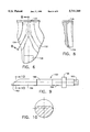
- FIG. 9 is a front elevational view of the diverter valve in accordance with the present invention.
- FIG. 10 is a sectional view of the diverter valve shown in FIG. 9 taken along the line 10--10.
- FIG. 11 is an enlarged, fragmentary view of the skin material flow divider of the assembly shown in FIG. 3.
- FIG. 12 is an enlarged, fragmentary view of an alternate embodiment of the diverter valve according to the present invention.
- FIGS. 1 and 2 there is shown a coextrusion arrangement including a first, lower extruder 18 and a second upper extruder 52, each of which provides plasticated material to a flow divider and extrusion die assembly 96.
- This arrangement of the two machines permits the extrusion of a predetermined shape from different materials, or from common base materials that each include different additives, such as color, for providing coextruded articles in a single extrusion operation.
- the two extruders 18, 52 are operated to provide a core material and a skin material to the flow divider and extrusion die assembly 96.
- the output from each of the extruders is divided into two flow paths to enable simultaneous extrusion of two profiles.
- First extruder 18 is positioned so that its longitudinal axis is disposed substantially horizontally, while second extruder 52 is positioned above first extruder 18 and has its longitudinal axis disposed at an angle to that of first extruder 18.
- the coextrusion arrangement is supported on a machine base 10 defined by a generally rectangular, box-type frame having an overall structure that is well known to those skilled in the art.
- Base 10 includes a base plate 14 at its uppermost portion, base plate 14 preferably being oriented so that its upper surface 16 lies substantially in a horizontal plane.
- first extruder 18 Carried by and secured to uppermost surface 16 of base plate 14 is first extruder 18 that incorporates a tubular extruder barrel 20 that has its axis extending in a substantially horizontal direction.
- Barrel 20 includes an inner, rotatable plastication screw (not shown) and a plurality of outer, resistance-type heater bands 22 to apply heat to the exterior of barrel 20.
- Heater bands 22 aid in softening the plastic material while the material is mechanically worked by the plastication screw and as the material is being conveyed within barrel 20 in a direction toward the barrel outlet 24 by the plastication screw.
- Barrel 20 includes a forward flange 26 at outlet 24, and it also includes a drive end 28 that permits a drive coupling (not shown) to couple the plastication screw with a drive gear system 30 which, in turn, is coupled with a reduction gearbox 32 that receives power from a screw drive motor 34.
- a drive motor cooling blower 36 is carried by the motor casing of motor 34.
- Barrel 20 includes an outer cover 38 that has a generally rectangular cross section and that has its inner surfaces spaced from the outer surface of barrel 20 and from the outer surfaces of heater bands 22.
- Adjacent drive end 28 of barrel 20 is a plastics material inlet 40 that receives pelletized or powdered plastic material that is placed in a feed hopper 42. The material is transported to inlet 40 by means of a feed screw drive motor 44 that drives a feed screw (not shown) carried within a feed screw housing 46.
- Hopper 42 and feed screw housing 46 are partially supported by the casing of drive gear system 30 by a feeder support member 48 that is carried by a support bracket 50.
- Second extruder 52 is also supported by machine base 10 and is carried on a pedestal 54 that extends upwardly from base plate 14.
- Pedestal 54 carries a support cradle 64 that, in turn, carries an upper extruder support frame 66, which is a generally rectangular structure formed from a plurality of box-type beams of known construction.
- the second extruder 52 is capable of angular and linear movement with respect to the first extruder 18.
- the support cradle 64 pivots on a shaft 62, with the angular position being determined by extension or retraction of jackscrews 60 connected between the base 10 and support cradle 64.
- support frame 66 includes parallel track members 108, 110 which engage a plurality of interiorly positioned, longitudinally aligned rollers 112. This construction permits the upper extruder support frame 66 to be shifted slidably along the support cradle 64 so that the extruder outlet 88 can be axially aligned and connected with divider 98.
- support frame 66 carries second extruder 52 and its related drive system. Included on support frame 66 are an extruder barrel 68 with cover 58, a rotatable extruder screw (not shown) positioned within the barrel 68, a screw drive coupling (not shown), a gearing system 70, a gearbox 72, and a drive motor 76 along with a drive motor cooling blower 74. Second extruder 52 and related components carried by support frame 66 are similar in structure and function to the corresponding parts forming a part of first extruder 18. Consequently, second extruder 52 includes a material inlet 78 that is in communication with a plastic material feed hopper 80 for receiving pelletized or powdered plastics material.
- a material feed screw drive motor 82 rotates a feed screw (not shown) carried within a feed screw housing 84 to carry the plastics material from feed hopper 80 to material inlet 78.
- a feed conduit adapter 86 is provided to permit feed screw housing 84 to be oriented so that its longitudinal axis is substantially in a horizontal plane.
- Second extruder 52 includes a barrel outlet 88 that includes a flange for connection of outlet 88 with a die entry adapter 90 by means of a split ring clamp 92.
- First extruder 18 includes a die entry adapter 27 that is also connected with first extruder outlet 26, by means of a split clamp 29.
- Each of die entry adapters 27, 90 is so configured that it can be easily connected at suitable connectors on the flow dividers 94, 98 of assembly 96, so that plasticated material can be conveyed from the respective first and second extruders 18, 52 to the assembly 96 where the flows of skin and core material are each divided then combined to form two coextruded profiles of predetermined shape.
- the entry adapters 27, 90 are provided with a bore 105 for connecting a melt thermocouple and/or a bore 106 to receive a probe for melt pressure, or other suitable sensors.
- the die entry adapters 27, 90 for the first and second extruders are connected to the respective extruder outlets 24, 88 by means of split clamp rings 29, 92.
- First extruder die entry adapter 27 is connected with core material flow divider 94 by a plurality of bolts 140 so that the flow passage in die entry adapter 27 is interconnected with first flow passage 142 in flow divider 94.
- Second extruder die entry adapter 90 is connected with a split flange arrangement 144 to interconnect securely the flow passage in die entry adapter 90 with second flow inlet passage 120 in flow divider 98.
- the plastic melt passes from the respective extruders 18, 52 into flow dividers 94, 98 and through appropriate connectors which equalize the flow velocities of the respective streams of plastics material, as required.
- flow divider 98 includes diverter valve 100 to provide the capability to alter the flow within the passages of the divider during the extrusion process, as will be more fully described later.
- the materials then flow into extrusion dies 102, 104 and ultimately issue as the defined profile configuration.
- many types of die housings for forming various extruded shapes can be provided, as desired.
- FIGS. 2, 3 and 5 there are shown the flow dividers 94, 98 according to the present invention, designed to separate the streams of plasticized core and skin material into two flow streams, enabling simultaneous extrusion of two profiles.
- the flow divider 98 as representative of the preferred construction, its body is made in two halves 114, 116 which are machined from rectangular steel blocks.
- the halves 114, 116 are essentially identical (see FIG. 5) with respect to forming a material flow path 118 having a flow entry 120 and subsequently dividing into two flow channels 122, 124.
- the halves 114, 116 are machined to form a bore 126 to receive the diverter valve 100.
- equal portions of the flow path 118 and bore 126 are formed in each half of the flow divider body, so that the desired configurations are fully formed when the halves 114, 116 are fastened together.
- through holes are provided in half 114 and threaded holes are provided in half 116 so that they can be connected together by bolts 127.
- each half 114, 116 of the dual flow divider 98 it is preferable to provide heating means within each half 114, 116 of the dual flow divider 98.
- the embodiment shown in the FIGS. 1 through 4 includes a series of suitably placed bores 130 to receive electric cartridge heaters 132 which can be controlled as required for consistent operation.
- the heaters 132 grouped in independently controlled zones see FIG. 4). For example, four banks of four heaters are shown, each bank of heaters 132 having a suitable connector 131 (FIG. 3) for interface with the machine control 180.
- Each of the channels 122, 124 are essentially circular in cross-section when the divider body is assembled, a semicircular portion of the channel being machined in each half 114, 116 of the divider body.
- adequate performance has been achieved by a flow divider having a channel diameter of 30 mm when used with a standard size extruder.
- the flow channel 122 and 124 diverge from the flow entry 120.
- the entry 120 is larger in area than the respective flow paths; a diameter of 40 mm is compatible with the 30 mm channel diameter suggested.
- each of the channels 122, 124 is deepened from its normal depth 134 to a deeper section 136 where the two channels merge to provide an enlarged opening at the entry 120.
- the phantom line at 138 in FIG. 7 illustrates the boundary of the material that is removed by the deeper section 136 to improve the entry 120 of flow path 118.
- the material at 138 were not removed, it would present a configuration which would restrict flow and tend to generate heat, resulting in a burning condition for heat sensitive materials, particularly at the corner formed at 139.
- Another point regarding the construction of the flow divider 98 is the provision of a sealing ledge 150 along the entire material flow path 118. Specifically, the ledge 150 extends not only along the channels 122, 124, but also forms a seal around the exits 152 and along the entry 120 of the halves 114, 116.
- valve 100 As noted previously, an important feature of the flow divider 98 is the provision of a diverter valve 100. As shown in FIGS. 9, 10 and 11, the valve 100 has an elongated body 148 with bearing surfaces 156 that are received in the bore 126 formed by the assembled halves 114, 116. The valve 100 also has a retaining shoulder 158 and a head 160 that are important for adjustment of the valve 100, as will be more fully discussed later.
- the valve 100 has a diverter end 162 that is designed to enter the material flow path 118 adjacent the entry 120 just before the flow is divided into channels 122, 124. As seen in the drawings, the diverter end 162 of the valve 100 is specially designed, as by rounding all edges and streamlining surfaces to avoid any corners or other geometry that would adversely affect the flow of heat sensitive material past the diverter end 162 of valve 100.
- the diverter valve 100 is held in the dual flow diverter 98 by means of a retaining plate 164 and bolts 166 which serve to trap the shoulder 158 in a recess 161 of bore 126.
- a retaining plate 164 and bolts 166 which serve to trap the shoulder 158 in a recess 161 of bore 126.
- the washers 168 can be put on either side of the retaining shoulder 158 to determine how far the diverter end 162 of the valve 100 will extend from the bore 126 into the flow path 118 adjacent the entry 120.
- each of the channels 122, 124 there are counterbores 170, 172 to receive an extrusion die adapter 174, or other appropriate die interface.
- the die adapter 174 is typically held in place by a retaining ring 176 and bolts 178.
- each of extruders 18 and 52 is operated in the normal manner; that operation can be accomplished in any conventional manner, as through a single operator control panel 180 containing the necessary switches, indicators, and controls. Simultaneous flows of plastics materials from each of the extruders enter the respective flow dividers, steams of each material are combined at the dies 102, 104 and issue as a single coextruded profile.
- an extruded section that can be used for siding for homes can be extruded using a base (core) material of polyvinyl chloride resin that flows from extruder 18.
- a cap stock or skin material can be arranged to flow from second extruder 52 to form a thin cover layer over the core material.
- the color, ultraviolet absorbers, and other expensive additives can be confined to the skin material, to thereby reduce the quantity of such additives that is needed, and thereby reduce the cost of the finished extruded product.
- each extruder produces plastic melt which exits the extruder under pressure, passing through the entry adapters 27, 90 and into the flow entry 120 of the material flow path 118.
- flow divider 98 the flow of plastic melt then encounters the diverter end 162 of the valve 100 just prior to the point where it is forced to separate into the separate channels 122, 124 of the material flow path 118.
- the diverter valve 100 is used to vary the relative flow resistance in the separate channels 122, 124.
- the diverter valve 100 can be used to balance effectively the flow in the respective channels 122, 124 to achieve the desired results.
- valve 100 is in a neutral position so that it has minimal effect on the plastic melt as it divides into separate flows.
- the valve 100 would be in a neutral position when the operation is started since the relative flow resistance in the respective flow channels 122, 124 is not yet known.
- the output of the respective dies 102, 104 is examined for quality and performance. If one profile is disproportionate with respect to the other, the valve 100 is rotated by means of the hex head 160 to alter the position of the diverter end 162. Specifically, the diverter end 162 is positioned so that it begins to obstruct the channel which leads to the die having the larger material flow, while simultaneously reducing the restriction of the other channel. This construction enables adjustment of flow resistance in fine increments to optimize processing without having to stop the extruder. If necessary, the flow rate or output of the extruder can also be altered to achieve the desired production results by means of the dual flow divider and extrusion die assembly 96.
- FIG. 12 An alternate embodiment for a valve arrangement according to the present invention is shown in FIG. 12.
- two separately adjustable valves can be used near the exits of the flow channels in flow divider 94. The following description of this embodiment will describe only one valve in detail; however, it will be readily apparent that a similar valve is needed in the other flow channel to maximize performance and capabilities of the divider.
- FIG. 12 shows a segment of the divider 94 where it attaches to the die 102, similar to the right-hand side of the assembly shown in FIG. 3.
- a bore 182 is provided in the flow divider 94 to intersect the right-hand channel 190 of flow passage 142 adjacent the point where channel 190 connects with the die 102.
- Received within the bore 182 is a restrictor valve 184.
- the valve 184 is fitted for adjustable, linear movement (without rotation) in the bore 182 in any suitable manner, as is well known in the art.
- the distal end (not shown) of the valve 184 could be threaded for adjustment, and keyed to engage a slot or recess in the divider body, thereby preventing rotation.
- a nut (not shown), trapped against the divider 94 and concentric with the bore 182, engages the treaded end of valve 184, such that rotation of the nut causes linear displacement of the valve 184.
- valve 184 is shown in its retracted position so that the end 186 has minimal effect on flow of material through the channel 190 when a full volume of flow is desired.
- the end 186 is contoured, as shown, to avoid "dead spots" around the point of entry of the valve 184 into the flow channel 190, while maintaining a rigid geometry for the end 186.
- the linear adjustment of valve 184 allows its position in the channel 190 to be infinitely variable from the retracted position shown to a fully extended position indicated at 188.
- valves 184 positioned in the divider 94 at locations similar to that shown in FIG. 12, it would also be necessary to streamline the contour of the flow channel 190 to minimize dead spots in the area where the bore 182 intersects the channel 190.
- the separate valves 184 provide further flexibility in making the adjustment in flow resistance for the paths leading to the respective dies fully independent of one another.
Abstract
Description
Claims (2)
Priority Applications (1)
| Application Number | Priority Date | Filing Date | Title |
|---|---|---|---|
| US08/781,253 US5711349A (en) | 1995-04-10 | 1997-01-10 | Flow divider with diverter valve |
Applications Claiming Priority (2)
| Application Number | Priority Date | Filing Date | Title |
|---|---|---|---|
| US08/419,306 US5616350A (en) | 1995-04-10 | 1995-04-10 | Dual flow divider with diverter valve |
| US08/781,253 US5711349A (en) | 1995-04-10 | 1997-01-10 | Flow divider with diverter valve |
Related Parent Applications (1)
| Application Number | Title | Priority Date | Filing Date |
|---|---|---|---|
| US08/419,306 Division US5616350A (en) | 1995-04-10 | 1995-04-10 | Dual flow divider with diverter valve |
Publications (1)
| Publication Number | Publication Date |
|---|---|
| US5711349A true US5711349A (en) | 1998-01-27 |
Family
ID=23661689
Family Applications (2)
| Application Number | Title | Priority Date | Filing Date |
|---|---|---|---|
| US08/419,306 Expired - Lifetime US5616350A (en) | 1995-04-10 | 1995-04-10 | Dual flow divider with diverter valve |
| US08/781,253 Expired - Lifetime US5711349A (en) | 1995-04-10 | 1997-01-10 | Flow divider with diverter valve |
Family Applications Before (1)
| Application Number | Title | Priority Date | Filing Date |
|---|---|---|---|
| US08/419,306 Expired - Lifetime US5616350A (en) | 1995-04-10 | 1995-04-10 | Dual flow divider with diverter valve |
Country Status (1)
| Country | Link |
|---|---|
| US (2) | US5616350A (en) |
Cited By (12)
| Publication number | Priority date | Publication date | Assignee | Title |
|---|---|---|---|---|
| US20020109258A1 (en) * | 2001-02-09 | 2002-08-15 | Hans Groeblacher | Method and system for dual co-extrusion |
| US6626206B1 (en) * | 2000-01-20 | 2003-09-30 | Extrusion Dies, Inc. | Feedblock for adjusting the dimensions of a set of co-extruded layers of a multi-layer sheet |
| US7743567B1 (en) | 2006-01-20 | 2010-06-29 | The Crane Group Companies Limited | Fiberglass/cellulosic composite and method for molding |
| US7913960B1 (en) | 2007-08-22 | 2011-03-29 | The Crane Group Companies Limited | Bracketing system |
| US8074339B1 (en) | 2004-11-22 | 2011-12-13 | The Crane Group Companies Limited | Methods of manufacturing a lattice having a distressed appearance |
| US20120073687A1 (en) * | 2010-09-27 | 2012-03-29 | Hanson Dana R | Diverter Valve |
| US8167275B1 (en) | 2005-11-30 | 2012-05-01 | The Crane Group Companies Limited | Rail system and method for assembly |
| US8460797B1 (en) | 2006-12-29 | 2013-06-11 | Timbertech Limited | Capped component and method for forming |
| US10207444B2 (en) | 2015-02-20 | 2019-02-19 | Processing Technologies, Llc | Diverter valve |
| US10220561B2 (en) | 2015-05-04 | 2019-03-05 | Nordson Corporation | Extrusion device and method of use |
| US10252457B2 (en) | 2015-05-04 | 2019-04-09 | Nordson Corporation | Flow diverter valve for an extrusion system |
| WO2021023663A1 (en) * | 2019-08-06 | 2021-02-11 | Kautex Maschinenbau Gmbh | Melt distributor |
Families Citing this family (14)
| Publication number | Priority date | Publication date | Assignee | Title |
|---|---|---|---|---|
| US5858420A (en) * | 1997-08-13 | 1999-01-12 | Husky Injection Molding Systems Ltd. | Flow regulating and distributing assembly |
| US6174478B1 (en) * | 1998-09-25 | 2001-01-16 | Silver-Line Plastics Corporation | Method and apparatus for simultaneous extrusion of two triple-wall pipes |
| US6478564B1 (en) * | 2000-09-08 | 2002-11-12 | The Goodyear Tire & Rubber Company | Adjustable flow channel for an extruder head |
| US6491510B1 (en) * | 2000-09-08 | 2002-12-10 | The Goodyear Tire & Rubber Company | Adjustable flow channel for an extruder head |
| US20040185132A1 (en) * | 2003-03-19 | 2004-09-23 | The Goodyear Tire & Rubber Company | Removable flow diverter for an extrusion head |
| US6821106B1 (en) | 2003-06-24 | 2004-11-23 | The Goodyear Tire & Rubber Company | Roller die preformer for wide extrusions |
| US6994821B1 (en) | 2003-07-28 | 2006-02-07 | Graham Engineering Corporation | Dual parison blow molding and method |
| US20060076703A1 (en) * | 2004-10-13 | 2006-04-13 | Looman Ernest W Jr | Double flow channel for an extruder head |
| TWI243743B (en) * | 2004-12-21 | 2005-11-21 | Ind Tech Res Inst | Material discharging device for a two-step injection molding machine |
| CA2659409C (en) | 2006-09-29 | 2014-05-20 | General Mills, Inc. | Apparatus and methods for fabricating food items |
| WO2010087977A2 (en) * | 2009-01-30 | 2010-08-05 | Lrm Industries International, Inc. | Method of forming a molded article from thermoformable thermoplastic sheets |
| US8328546B2 (en) * | 2010-06-29 | 2012-12-11 | Mold-Masters (2007) Limited | Auxiliary injection unit integrated in injection molding system |
| CN107186985B (en) * | 2017-06-16 | 2023-10-13 | 常州金纬管道科技有限公司 | Composite extrusion system of pipe production line |
| US10974432B2 (en) * | 2017-09-26 | 2021-04-13 | Nordson Corporation | Extrusion system including an edge encapsulation block |
Citations (7)
| Publication number | Priority date | Publication date | Assignee | Title |
|---|---|---|---|---|
| US3199537A (en) * | 1963-03-11 | 1965-08-10 | Hart Carter Co | Diverter valve |
| US3545489A (en) * | 1968-07-02 | 1970-12-08 | North American Rockwell | Tool diverter for directing tfl tools |
| US3901636A (en) * | 1973-06-11 | 1975-08-26 | Beloit Corp | Plastic extrusion and odor elimination apparatus |
| US4049105A (en) * | 1975-11-07 | 1977-09-20 | Kamyr Incorporated | Diverter valve |
| US4055280A (en) * | 1976-06-01 | 1977-10-25 | King-Seeley Thermos Co. | Diverter valve assembly for ice distribution systems |
| US4836250A (en) * | 1987-09-04 | 1989-06-06 | Avt Anlagen- Und Verfahrenstechnik Gmbh | Device for closing a pipe branch |
| US4840028A (en) * | 1987-03-20 | 1989-06-20 | Matsushita Electric Industrial Co., Ltd. | Purifier of diesel particulates in exhaust gas |
Family Cites Families (12)
| Publication number | Priority date | Publication date | Assignee | Title |
|---|---|---|---|---|
| FR2087753A5 (en) * | 1970-05-29 | 1971-12-31 | Saint Gobain | |
| US4032279A (en) * | 1975-09-08 | 1977-06-28 | The B. F. Goodrich Company | Extrusion adapter |
| US4076477A (en) * | 1975-12-08 | 1978-02-28 | Grandview Industries Limited | Multiple extrusion apparatus |
| ES222540Y (en) * | 1976-07-26 | 1977-03-16 | Cables De Comunicaciones, S. A. | HEAD FOR MULTIPLE INSULATION OF CONDUCTORS. |
| US4107246A (en) * | 1976-12-20 | 1978-08-15 | Phillips Petroleum Company | Extrusion control |
| US4081231A (en) * | 1976-12-23 | 1978-03-28 | Mobil Oil Corporation | Flow distribution valve for dual thermoplastic tube extrusion |
| US4302172A (en) * | 1980-05-15 | 1981-11-24 | Leesona Corporation | Extrusion die assembly |
| IT1129467B (en) * | 1980-12-19 | 1986-06-04 | Lavorazione Mat Plast | ADAPTER FOR SIMULTANEOUS EXTRUSION OF MULTIPLE THREADS OF SYNTHETIC THERMOPLASTIC FOAM USING A SINGLE EXTRUDER |
| US4521359A (en) * | 1981-12-04 | 1985-06-04 | Exxon Research & Engineering Co. | Method of coextruding plastics to form a composite sheet |
| US5110276A (en) * | 1989-12-28 | 1992-05-05 | Farnsworth John T | Extrusion die assembly |
| US5076777A (en) * | 1990-12-20 | 1991-12-31 | Cincinnati Milacron Inc. | Apparatus for coextruding plastics materials |
| US5507631A (en) * | 1994-04-21 | 1996-04-16 | Basf Corporation | Cam pump for the production of alternating sequences of polymer flow pulses |
-
1995
- 1995-04-10 US US08/419,306 patent/US5616350A/en not_active Expired - Lifetime
-
1997
- 1997-01-10 US US08/781,253 patent/US5711349A/en not_active Expired - Lifetime
Patent Citations (7)
| Publication number | Priority date | Publication date | Assignee | Title |
|---|---|---|---|---|
| US3199537A (en) * | 1963-03-11 | 1965-08-10 | Hart Carter Co | Diverter valve |
| US3545489A (en) * | 1968-07-02 | 1970-12-08 | North American Rockwell | Tool diverter for directing tfl tools |
| US3901636A (en) * | 1973-06-11 | 1975-08-26 | Beloit Corp | Plastic extrusion and odor elimination apparatus |
| US4049105A (en) * | 1975-11-07 | 1977-09-20 | Kamyr Incorporated | Diverter valve |
| US4055280A (en) * | 1976-06-01 | 1977-10-25 | King-Seeley Thermos Co. | Diverter valve assembly for ice distribution systems |
| US4840028A (en) * | 1987-03-20 | 1989-06-20 | Matsushita Electric Industrial Co., Ltd. | Purifier of diesel particulates in exhaust gas |
| US4836250A (en) * | 1987-09-04 | 1989-06-06 | Avt Anlagen- Und Verfahrenstechnik Gmbh | Device for closing a pipe branch |
Cited By (26)
| Publication number | Priority date | Publication date | Assignee | Title |
|---|---|---|---|---|
| US6626206B1 (en) * | 2000-01-20 | 2003-09-30 | Extrusion Dies, Inc. | Feedblock for adjusting the dimensions of a set of co-extruded layers of a multi-layer sheet |
| US20020109258A1 (en) * | 2001-02-09 | 2002-08-15 | Hans Groeblacher | Method and system for dual co-extrusion |
| US6793474B2 (en) * | 2001-02-09 | 2004-09-21 | American Maplan Corporation | Method and system for dual co-extrusion |
| US20050006810A1 (en) * | 2001-02-09 | 2005-01-13 | American Maplan Corporation | Method and system for dual co-extrusion |
| US7122141B2 (en) | 2001-02-09 | 2006-10-17 | American Maplan Corporation | Method and system for dual co-extrusion |
| US8074339B1 (en) | 2004-11-22 | 2011-12-13 | The Crane Group Companies Limited | Methods of manufacturing a lattice having a distressed appearance |
| US10358841B2 (en) | 2005-11-30 | 2019-07-23 | Cpg International Llc | Rail system and method for assembly |
| USD797307S1 (en) | 2005-11-30 | 2017-09-12 | Cpg International Llc | Rail assembly |
| US8167275B1 (en) | 2005-11-30 | 2012-05-01 | The Crane Group Companies Limited | Rail system and method for assembly |
| US9822547B2 (en) | 2005-11-30 | 2017-11-21 | Cpg International Llc | Rail system and method for assembly |
| USD797953S1 (en) | 2005-11-30 | 2017-09-19 | Cpg International Llc | Rail assembly |
| USD782698S1 (en) | 2005-11-30 | 2017-03-28 | Cpg International Llc | Rail |
| USD782697S1 (en) | 2005-11-30 | 2017-03-28 | Cpg International Llc | Rail |
| USD787707S1 (en) | 2005-11-30 | 2017-05-23 | Cpg International Llc | Rail |
| USD788329S1 (en) | 2005-11-30 | 2017-05-30 | Cpg International Llc | Post cover |
| US7743567B1 (en) | 2006-01-20 | 2010-06-29 | The Crane Group Companies Limited | Fiberglass/cellulosic composite and method for molding |
| US8460797B1 (en) | 2006-12-29 | 2013-06-11 | Timbertech Limited | Capped component and method for forming |
| US7913960B1 (en) | 2007-08-22 | 2011-03-29 | The Crane Group Companies Limited | Bracketing system |
| USRE45965E1 (en) * | 2010-09-27 | 2016-04-05 | Processing Technologies, Llc | Diverter valve |
| US8490643B2 (en) * | 2010-09-27 | 2013-07-23 | Processing Technologies, Llc | Diverter valve |
| US20120073687A1 (en) * | 2010-09-27 | 2012-03-29 | Hanson Dana R | Diverter Valve |
| US10207444B2 (en) | 2015-02-20 | 2019-02-19 | Processing Technologies, Llc | Diverter valve |
| US10220561B2 (en) | 2015-05-04 | 2019-03-05 | Nordson Corporation | Extrusion device and method of use |
| US10252457B2 (en) | 2015-05-04 | 2019-04-09 | Nordson Corporation | Flow diverter valve for an extrusion system |
| WO2021023663A1 (en) * | 2019-08-06 | 2021-02-11 | Kautex Maschinenbau Gmbh | Melt distributor |
| CN114364504A (en) * | 2019-08-06 | 2022-04-15 | 考特斯机械制造有限公司 | Melt distributor |
Also Published As
| Publication number | Publication date |
|---|---|
| US5616350A (en) | 1997-04-01 |
Similar Documents
| Publication | Publication Date | Title |
|---|---|---|
| US5711349A (en) | Flow divider with diverter valve | |
| US5076777A (en) | Apparatus for coextruding plastics materials | |
| EP0092188B1 (en) | Coextrusion die | |
| US5223276A (en) | Multilayer coextrusion apparatus | |
| EP0457991B1 (en) | Multiple layer die head with adjustable gaps | |
| US4405547A (en) | Method of coextruding diverse materials | |
| US4888146A (en) | Method and apparatus of forming extruded article | |
| US3877857A (en) | Multiple melt chamber extrusion die | |
| EP0050476B1 (en) | Coextrusion device and method | |
| CA1147920A (en) | Method of and apparatus for extruding plastics products | |
| US7384254B2 (en) | Coextrusion adapter | |
| EP2734353B1 (en) | Concentric co - extrusion die and a method of extruding a multilayer thermoplastic film | |
| KR930000735B1 (en) | Rapid change die assembly | |
| US2977632A (en) | Centripetal extruder | |
| US3930782A (en) | Apparatus for extruding plastic material | |
| US4723902A (en) | Balanced flow extrusion crosshead and die assembly | |
| US4548570A (en) | Extrusion apparatus for producing thermoplastic pipe | |
| US5567369A (en) | Method for die lip temperature adjustment in a thermoplastic extruder | |
| US6533974B1 (en) | Method of forming a profile on a foam rod | |
| US3677863A (en) | Dies for producing multi-layer tubes or films | |
| EP0834386A1 (en) | Apparatus for producing double walled plastic pipes | |
| US4032279A (en) | Extrusion adapter | |
| JPS6238132B2 (en) | ||
| US4512943A (en) | Extrusion process for producing thermoplastic pipe | |
| US3784339A (en) | Disk extruder |
Legal Events
| Date | Code | Title | Description |
|---|---|---|---|
| STCF | Information on status: patent grant |
Free format text: PATENTED CASE |
|
| FEPP | Fee payment procedure |
Free format text: PAYOR NUMBER ASSIGNED (ORIGINAL EVENT CODE: ASPN); ENTITY STATUS OF PATENT OWNER: LARGE ENTITY |
|
| AS | Assignment |
Owner name: UNILOY MILACRON USA INC., MICHIGAN Free format text: ASSIGNMENT OF ASSIGNORS INTEREST;ASSIGNOR:MILACRON INC.;REEL/FRAME:011887/0236 Effective date: 20000101 |
|
| FPAY | Fee payment |
Year of fee payment: 4 |
|
| AS | Assignment |
Owner name: BANKERS TRUST COMPANY, AS ADMINISTRATIVE AGENT, NE Free format text: SECURITY AGREEMENT;ASSIGNORS:VALENITE U.S.A. INC.;MILACRON INC.;TALBOT HOLDINGS, LTD.;AND OTHERS;REEL/FRAME:013110/0122 Effective date: 20011210 |
|
| AS | Assignment |
Owner name: CREDIT SUISSE FIRST BOSTON, ACTING THROUGH ITS CAY Free format text: SECURITY INTEREST;ASSIGNOR:UNILOY MILACRON U.S.A. INC.;REEL/FRAME:014438/0413 Effective date: 20040312 |
|
| AS | Assignment |
Owner name: UNILOY MILACRON U.S.A. INC., OHIO Free format text: RELEASE;ASSIGNOR:DEUTSCHE BANK TRUST COMPANY AMERICAS (F/K/A BANKERS TRUST COMPANY);REEL/FRAME:015209/0817 Effective date: 20040312 |
|
| AS | Assignment |
Owner name: JP MORGAN CHASE BANK, NEW YORK Free format text: SECURITY AGREEMENT;ASSIGNORS:UNILOY MILACRON INC.;D-M-E U.S.A. INC.;MILACRON INC.;AND OTHERS;REEL/FRAME:014763/0181 Effective date: 20040610 |
|
| AS | Assignment |
Owner name: U.S. BANK NATIONAL ASSOCIATION, OHIO Free format text: SECURITY INTEREST;ASSIGNOR:UNILOY MILACRON U.S.A. INC.;REEL/FRAME:015442/0691 Effective date: 20040610 |
|
| AS | Assignment |
Owner name: D-M-E COMPANY, MICHIGAN Free format text: RELEASE OF LIEN IN PATENTS;ASSIGNOR:CREIDT SUISSE FIRST BOSTON, ACTING THROUGH ITS CAYMAN ISLANDS BRANCH ONE MADISON AVENUE NEW YORK, NY 10010;REEL/FRAME:014852/0375 Effective date: 20040610 Owner name: D-M-E U.S.A. INC., MICHIGAN Free format text: RELEASE OF LIEN IN PATENTS;ASSIGNOR:CREIDT SUISSE FIRST BOSTON, ACTING THROUGH ITS CAYMAN ISLANDS BRANCH ONE MADISON AVENUE NEW YORK, NY 10010;REEL/FRAME:014852/0375 Effective date: 20040610 Owner name: MILACRON INC., OHIO Free format text: RELEASE OF LIEN IN PATENTS;ASSIGNOR:CREIDT SUISSE FIRST BOSTON, ACTING THROUGH ITS CAYMAN ISLANDS BRANCH ONE MADISON AVENUE NEW YORK, NY 10010;REEL/FRAME:014852/0375 Effective date: 20040610 Owner name: MILACRON INDUSTRIAL PRODUCTS, INC., MICHIGAN Free format text: RELEASE OF LIEN IN PATENTS;ASSIGNOR:CREIDT SUISSE FIRST BOSTON, ACTING THROUGH ITS CAYMAN ISLANDS BRANCH ONE MADISON AVENUE NEW YORK, NY 10010;REEL/FRAME:014852/0375 Effective date: 20040610 Owner name: OAK INTERNATIONAL, INC., MICHIGAN Free format text: RELEASE OF LIEN IN PATENTS;ASSIGNOR:CREIDT SUISSE FIRST BOSTON, ACTING THROUGH ITS CAYMAN ISLANDS BRANCH ONE MADISON AVENUE NEW YORK, NY 10010;REEL/FRAME:014852/0375 Effective date: 20040610 Owner name: UNILOY MILACRON U.S.A. INC., MICHIGAN Free format text: RELEASE OF LIEN IN PATENTS;ASSIGNOR:CREIDT SUISSE FIRST BOSTON, ACTING THROUGH ITS CAYMAN ISLANDS BRANCH ONE MADISON AVENUE NEW YORK, NY 10010;REEL/FRAME:014852/0375 Effective date: 20040610 Owner name: UNILOY MILACRON, INC., MICHIGAN Free format text: RELEASE OF LIEN IN PATENTS;ASSIGNOR:CREIDT SUISSE FIRST BOSTON, ACTING THROUGH ITS CAYMAN ISLANDS BRANCH ONE MADISON AVENUE NEW YORK, NY 10010;REEL/FRAME:014852/0375 Effective date: 20040610 |
|
| FPAY | Fee payment |
Year of fee payment: 8 |
|
| AS | Assignment |
Owner name: GENERAL ELECTRIC CAPITAL CORPORATION, AS AGENT, CO Free format text: SECURITY AGREEMENT;ASSIGNORS:MILACRON INC.;D-M-E U.S.A. INC.;MILACRON INDUSTRIAL PRODUCTS, INC.;AND OTHERS;REEL/FRAME:018688/0070 Effective date: 20061219 Owner name: GENERAL ELECTRIC CAPITAL CORPORATION, AS AGENT,CON Free format text: SECURITY AGREEMENT;ASSIGNORS:MILACRON INC.;D-M-E U.S.A. INC.;MILACRON INDUSTRIAL PRODUCTS, INC.;AND OTHERS;REEL/FRAME:018688/0070 Effective date: 20061219 Owner name: UNILOY MILACRON INC.,MICHIGAN Free format text: RELEASE BY SECURED PARTY;ASSIGNOR:JPMORGAN CHASE BANK, N.A.;REEL/FRAME:018688/0001 Effective date: 20061219 Owner name: OAK INTERNATIONAL, INC.,MICHIGAN Free format text: RELEASE BY SECURED PARTY;ASSIGNOR:JPMORGAN CHASE BANK, N.A.;REEL/FRAME:018688/0001 Effective date: 20061219 Owner name: MILACRON INDUSTRIAL PRODUCTS, INC.,MICHIGAN Free format text: RELEASE BY SECURED PARTY;ASSIGNOR:JPMORGAN CHASE BANK, N.A.;REEL/FRAME:018688/0001 Effective date: 20061219 Owner name: D-M-E COMPANY,MICHIGAN Free format text: RELEASE BY SECURED PARTY;ASSIGNOR:JPMORGAN CHASE BANK, N.A.;REEL/FRAME:018688/0001 Effective date: 20061219 Owner name: MILACRON INC.,OHIO Free format text: RELEASE BY SECURED PARTY;ASSIGNOR:JPMORGAN CHASE BANK, N.A.;REEL/FRAME:018688/0001 Effective date: 20061219 Owner name: D-M-E U.S.A. INC,MICHIGAN Free format text: RELEASE BY SECURED PARTY;ASSIGNOR:JPMORGAN CHASE BANK, N.A.;REEL/FRAME:018688/0001 Effective date: 20061219 Owner name: UNILOY MILACRON U.S.A. INC.,MICHIGAN Free format text: RELEASE BY SECURED PARTY;ASSIGNOR:JPMORGAN CHASE BANK, N.A.;REEL/FRAME:018688/0001 Effective date: 20061219 Owner name: UNILOY MILACRON INC., MICHIGAN Free format text: RELEASE BY SECURED PARTY;ASSIGNOR:JPMORGAN CHASE BANK, N.A.;REEL/FRAME:018688/0001 Effective date: 20061219 Owner name: OAK INTERNATIONAL, INC., MICHIGAN Free format text: RELEASE BY SECURED PARTY;ASSIGNOR:JPMORGAN CHASE BANK, N.A.;REEL/FRAME:018688/0001 Effective date: 20061219 Owner name: D-M-E U.S.A. INC, MICHIGAN Free format text: RELEASE BY SECURED PARTY;ASSIGNOR:JPMORGAN CHASE BANK, N.A.;REEL/FRAME:018688/0001 Effective date: 20061219 Owner name: MILACRON INDUSTRIAL PRODUCTS, INC., MICHIGAN Free format text: RELEASE BY SECURED PARTY;ASSIGNOR:JPMORGAN CHASE BANK, N.A.;REEL/FRAME:018688/0001 Effective date: 20061219 Owner name: MILACRON INC., OHIO Free format text: RELEASE BY SECURED PARTY;ASSIGNOR:JPMORGAN CHASE BANK, N.A.;REEL/FRAME:018688/0001 Effective date: 20061219 Owner name: D-M-E COMPANY, MICHIGAN Free format text: RELEASE BY SECURED PARTY;ASSIGNOR:JPMORGAN CHASE BANK, N.A.;REEL/FRAME:018688/0001 Effective date: 20061219 Owner name: UNILOY MILACRON U.S.A. INC., MICHIGAN Free format text: RELEASE BY SECURED PARTY;ASSIGNOR:JPMORGAN CHASE BANK, N.A.;REEL/FRAME:018688/0001 Effective date: 20061219 |
|
| AS | Assignment |
Owner name: GENERAL ELECTRIC CAPITAL CORPORATION, AS AGENT, CO Free format text: SECURITY AGREEMENT;ASSIGNORS:MILACRON INC;CIMCOOL INDUSTRIAL PRODUCTS INC.;MILACRON MARKETING COMPANY;AND OTHERS;REEL/FRAME:022427/0080 Effective date: 20090311 Owner name: GENERAL ELECTRIC CAPITAL CORPORATION, AS AGENT,CON Free format text: SECURITY AGREEMENT;ASSIGNORS:MILACRON INC;CIMCOOL INDUSTRIAL PRODUCTS INC.;MILACRON MARKETING COMPANY;AND OTHERS;REEL/FRAME:022427/0080 Effective date: 20090311 |
|
| AS | Assignment |
Owner name: MILACRON INC., OHIO Free format text: ASSIGNMENT OF ASSIGNORS INTEREST;ASSIGNOR:MILACRON PLASTIC TECHNOLOGIES GROUP INC.;REEL/FRAME:022878/0553 Effective date: 20081231 Owner name: MILACRON PLASTICS TECHNOLOGIES GROUP INC., OHIO Free format text: ASSIGNMENT OF ASSIGNORS INTEREST;ASSIGNOR:UNILOY MILACRON USA INC.;REEL/FRAME:022878/0541 Effective date: 20081231 |
|
| FPAY | Fee payment |
Year of fee payment: 12 |
|
| AS | Assignment |
Owner name: D-M-E COMPANY, INC., MICHIGAN Free format text: RELEASE BY SECURED PARTY;ASSIGNOR:U.S. BANK NATIONAL ASSOCIATION, AS TRUSTEE AND COLLATERAL AGENT;REEL/FRAME:023134/0432 Effective date: 20090821 Owner name: D-M-E U.S.A. INC., MICHIGAN Free format text: RELEASE BY SECURED PARTY;ASSIGNOR:U.S. BANK NATIONAL ASSOCIATION, AS TRUSTEE AND COLLATERAL AGENT;REEL/FRAME:023134/0432 Effective date: 20090821 Owner name: MILACRON INC., OHIO Free format text: RELEASE BY SECURED PARTY;ASSIGNOR:U.S. BANK NATIONAL ASSOCIATION, AS TRUSTEE AND COLLATERAL AGENT;REEL/FRAME:023134/0432 Effective date: 20090821 Owner name: MILACRON INDUSTRIAL PRODUCTS INC., MICHIGAN Free format text: RELEASE BY SECURED PARTY;ASSIGNOR:U.S. BANK NATIONAL ASSOCIATION, AS TRUSTEE AND COLLATERAL AGENT;REEL/FRAME:023134/0432 Effective date: 20090821 Owner name: OAK INTERNATIONAL, INC., MICHIGAN Free format text: RELEASE BY SECURED PARTY;ASSIGNOR:U.S. BANK NATIONAL ASSOCIATION, AS TRUSTEE AND COLLATERAL AGENT;REEL/FRAME:023134/0432 Effective date: 20090821 Owner name: UNILOY MILACRON INC., MICHIGAN Free format text: RELEASE BY SECURED PARTY;ASSIGNOR:U.S. BANK NATIONAL ASSOCIATION, AS TRUSTEE AND COLLATERAL AGENT;REEL/FRAME:023134/0432 Effective date: 20090821 Owner name: UNILOY MILACRON U.S.A. INC., MICHIGAN Free format text: RELEASE BY SECURED PARTY;ASSIGNOR:U.S. BANK NATIONAL ASSOCIATION, AS TRUSTEE AND COLLATERAL AGENT;REEL/FRAME:023134/0432 Effective date: 20090821 Owner name: D-M-E COMPANY, INC.,MICHIGAN Free format text: RELEASE BY SECURED PARTY;ASSIGNOR:U.S. BANK NATIONAL ASSOCIATION, AS TRUSTEE AND COLLATERAL AGENT;REEL/FRAME:023134/0432 Effective date: 20090821 Owner name: D-M-E U.S.A. INC.,MICHIGAN Free format text: RELEASE BY SECURED PARTY;ASSIGNOR:U.S. BANK NATIONAL ASSOCIATION, AS TRUSTEE AND COLLATERAL AGENT;REEL/FRAME:023134/0432 Effective date: 20090821 Owner name: MILACRON INC.,OHIO Free format text: RELEASE BY SECURED PARTY;ASSIGNOR:U.S. BANK NATIONAL ASSOCIATION, AS TRUSTEE AND COLLATERAL AGENT;REEL/FRAME:023134/0432 Effective date: 20090821 Owner name: MILACRON INDUSTRIAL PRODUCTS INC.,MICHIGAN Free format text: RELEASE BY SECURED PARTY;ASSIGNOR:U.S. BANK NATIONAL ASSOCIATION, AS TRUSTEE AND COLLATERAL AGENT;REEL/FRAME:023134/0432 Effective date: 20090821 Owner name: OAK INTERNATIONAL, INC.,MICHIGAN Free format text: RELEASE BY SECURED PARTY;ASSIGNOR:U.S. BANK NATIONAL ASSOCIATION, AS TRUSTEE AND COLLATERAL AGENT;REEL/FRAME:023134/0432 Effective date: 20090821 Owner name: UNILOY MILACRON INC.,MICHIGAN Free format text: RELEASE BY SECURED PARTY;ASSIGNOR:U.S. BANK NATIONAL ASSOCIATION, AS TRUSTEE AND COLLATERAL AGENT;REEL/FRAME:023134/0432 Effective date: 20090821 Owner name: UNILOY MILACRON U.S.A. INC.,MICHIGAN Free format text: RELEASE BY SECURED PARTY;ASSIGNOR:U.S. BANK NATIONAL ASSOCIATION, AS TRUSTEE AND COLLATERAL AGENT;REEL/FRAME:023134/0432 Effective date: 20090821 |
|
| AS | Assignment |
Owner name: WELLS FARGO FOOTHILL, LLC, AS AGENT, GEORGIA Free format text: SECURITY AGREEMENT;ASSIGNORS:MILACRON LLC;DME COMPANY LLC;REEL/FRAME:023134/0669 Effective date: 20090821 Owner name: WELLS FARGO FOOTHILL, LLC, AS AGENT,GEORGIA Free format text: SECURITY AGREEMENT;ASSIGNORS:MILACRON LLC;DME COMPANY LLC;REEL/FRAME:023134/0669 Effective date: 20090821 |
|
| AS | Assignment |
Owner name: MILACRON LLC, OHIO Free format text: ASSIGNMENT OF ASSIGNORS INTEREST;ASSIGNOR:MILACRON INC.;REEL/FRAME:023163/0565 Effective date: 20090818 Owner name: MILACRON LLC,OHIO Free format text: ASSIGNMENT OF ASSIGNORS INTEREST;ASSIGNOR:MILACRON INC.;REEL/FRAME:023163/0565 Effective date: 20090818 |
|
| AS | Assignment |
Owner name: MILACRON INC., OHIO Free format text: RELEASE BY SECURED PARTY;ASSIGNOR:GENERAL ELECTRIC CAPITAL CORPORATION, AS AGENT;REEL/FRAME:023180/0690 Effective date: 20090821 Owner name: MILACRON MARKETING COMPANY, OHIO Free format text: RELEASE BY SECURED PARTY;ASSIGNOR:GENERAL ELECTRIC CAPITAL CORPORATION, AS AGENT;REEL/FRAME:023180/0690 Effective date: 20090821 Owner name: MILACRON PLASTICS TECHNOLOGIES GROUP INC., OHIO Free format text: RELEASE BY SECURED PARTY;ASSIGNOR:GENERAL ELECTRIC CAPITAL CORPORATION, AS AGENT;REEL/FRAME:023180/0690 Effective date: 20090821 Owner name: D-M-E COMPANY, INC., MICHIGAN Free format text: RELEASE BY SECURED PARTY;ASSIGNOR:GENERAL ELECTRIC CAPITAL CORPORATION, AS AGENT;REEL/FRAME:023180/0690 Effective date: 20090821 Owner name: CIMCOOL INDUSTRIAL PRODUCTS INC., OHIO Free format text: RELEASE BY SECURED PARTY;ASSIGNOR:GENERAL ELECTRIC CAPITAL CORPORATION, AS AGENT;REEL/FRAME:023180/0690 Effective date: 20090821 Owner name: MILACRON INC.,OHIO Free format text: RELEASE BY SECURED PARTY;ASSIGNOR:GENERAL ELECTRIC CAPITAL CORPORATION, AS AGENT;REEL/FRAME:023180/0690 Effective date: 20090821 Owner name: MILACRON MARKETING COMPANY,OHIO Free format text: RELEASE BY SECURED PARTY;ASSIGNOR:GENERAL ELECTRIC CAPITAL CORPORATION, AS AGENT;REEL/FRAME:023180/0690 Effective date: 20090821 Owner name: MILACRON PLASTICS TECHNOLOGIES GROUP INC.,OHIO Free format text: RELEASE BY SECURED PARTY;ASSIGNOR:GENERAL ELECTRIC CAPITAL CORPORATION, AS AGENT;REEL/FRAME:023180/0690 Effective date: 20090821 Owner name: D-M-E COMPANY, INC.,MICHIGAN Free format text: RELEASE BY SECURED PARTY;ASSIGNOR:GENERAL ELECTRIC CAPITAL CORPORATION, AS AGENT;REEL/FRAME:023180/0690 Effective date: 20090821 Owner name: CIMCOOL INDUSTRIAL PRODUCTS INC.,OHIO Free format text: RELEASE BY SECURED PARTY;ASSIGNOR:GENERAL ELECTRIC CAPITAL CORPORATION, AS AGENT;REEL/FRAME:023180/0690 Effective date: 20090821 |
|
| AS | Assignment |
Owner name: THE BANK OF NEW YORK MELLON, TEXAS Free format text: SECOND LIEN PATENT SECURITY AGREEMENT;ASSIGNORS:MILACRON LLC;DME COMPANY LLC;REEL/FRAME:023449/0926 Effective date: 20091021 Owner name: THE BANK OF NEW YORK MELLON,TEXAS Free format text: SECOND LIEN PATENT SECURITY AGREEMENT;ASSIGNORS:MILACRON LLC;DME COMPANY LLC;REEL/FRAME:023449/0926 Effective date: 20091021 |
|
| AS | Assignment |
Owner name: BANK OF AMERICA, N.A., AS ADMINISTRATIVE AGENT, IL Free format text: SECURITY AGREEMENT;ASSIGNORS:MILACRON LLC;DME COMPANY LLC;REEL/FRAME:026341/0357 Effective date: 20110506 Owner name: MILACRON LLC, OHIO Free format text: SECURITY AGREEMENT;ASSIGNOR:THE BANK OF NEW YORK MELLON;REEL/FRAME:026344/0926 Effective date: 20110506 |
|
| AS | Assignment |
Owner name: MILACRON LLC, OHIO Free format text: RELEASE BY SECURED PARTY;ASSIGNOR:WELLS FARGO CAPITAL FINANCE LLC;REEL/FRAME:028130/0164 Effective date: 20120430 |
|
| AS | Assignment |
Owner name: DME COMPANY LLC, MICHIGAN Free format text: PATENT RELEASE;ASSIGNOR:BANK OF AMERICA, N.A., AS ADMINISTRATIVE AGENT;REEL/FRAME:028153/0392 Effective date: 20120430 |
|
| AS | Assignment |
Owner name: U.S. BANK NATIONAL ASSOCIATION, AS NOTES COLLATERA Free format text: SECURITY AGREEMENT;ASSIGNORS:DME COMPANY LLC;MILACRON LLC;REEL/FRAME:028154/0084 Effective date: 20120430 |
|
| AS | Assignment |
Owner name: BANK OF AMERICA, N.A., AS COLLATERAL AGENT, WISCON Free format text: SECURITY AGREEMENT;ASSIGNORS:DME COMPANY LLC;MILACRON LLC;REEL/FRAME:028168/0689 Effective date: 20120430 |
|
| AS | Assignment |
Owner name: U.S. BANK NATIONAL ASSOCIATION, AS NOTES COLLATERA Free format text: SECURITY AGREEMENT;ASSIGNORS:MILACRON LLC;DME COMPANY LLC;REEL/FRAME:030201/0510 Effective date: 20130328 |
|
| AS | Assignment |
Owner name: DME COMPANY LLC, MICHIGAN Free format text: RELEASE OF INTELLECTUAL PROPERTY SECURITY AGREEMENT;ASSIGNOR:U.S. BANK NATIONAL ASSOCIATION;REEL/FRAME:035668/0634 Effective date: 20150514 Owner name: MILACRON LLC, OHIO Free format text: RELEASE OF INTELLECTUAL PROPERTY SECURITY AGREEMENT;ASSIGNOR:U.S. BANK NATIONAL ASSOCIATION;REEL/FRAME:035668/0634 Effective date: 20150514 Owner name: KORTEC, INC., OHIO Free format text: RELEASE OF INTELLECTUAL PROPERTY SECURITY AGREEMENT;ASSIGNOR:U.S. BANK NATIONAL ASSOCIATION;REEL/FRAME:035668/0634 Effective date: 20150514 |
|
| AS | Assignment |
Owner name: JPMORGAN CHASE BANK, N.A., AS COLLATERAL AGENT, IL Free format text: SECURITY AGREEMENT;ASSIGNORS:MILACRON LLC;DME COMPANY LLC, A DELAWARE LIMITED LIABILITY COMPANY;KORTEC, INC., A MASSACHUSETTS CORPORATION;REEL/FRAME:035707/0098 Effective date: 20150514 |
|
| AS | Assignment |
Owner name: MILACRON LLC, OHIO Free format text: RELEASE BY SECURED PARTY;ASSIGNOR:JPMORGAN CHASE BANK, N.A.;REEL/FRAME:051094/0944 Effective date: 20191121 Owner name: DME COMPANY LLC, MICHIGAN Free format text: RELEASE BY SECURED PARTY;ASSIGNOR:BANK OF AMERICA, N.A.;REEL/FRAME:051094/0964 Effective date: 20191121 Owner name: MILACRON MARKETING COMPANY LLC, OHIO Free format text: RELEASE BY SECURED PARTY;ASSIGNOR:JPMORGAN CHASE BANK, N.A.;REEL/FRAME:051094/0944 Effective date: 20191121 Owner name: DME COMPANY LLC, MICHIGAN Free format text: RELEASE BY SECURED PARTY;ASSIGNOR:JPMORGAN CHASE BANK, N.A.;REEL/FRAME:051094/0944 Effective date: 20191121 Owner name: MILACRON LLC, OHIO Free format text: RELEASE BY SECURED PARTY;ASSIGNOR:BANK OF AMERICA, N.A.;REEL/FRAME:051094/0964 Effective date: 20191121 |