US5711907A - Method for producing a weather strip for a motor vehicle - Google Patents
Method for producing a weather strip for a motor vehicle Download PDFInfo
- Publication number
- US5711907A US5711907A US08/602,446 US60244696A US5711907A US 5711907 A US5711907 A US 5711907A US 60244696 A US60244696 A US 60244696A US 5711907 A US5711907 A US 5711907A
- Authority
- US
- United States
- Prior art keywords
- core
- weather strip
- tubular
- base portion
- tubular part
- Prior art date
- Legal status (The legal status is an assumption and is not a legal conclusion. Google has not performed a legal analysis and makes no representation as to the accuracy of the status listed.)
- Expired - Fee Related
Links
Images


Classifications
-
- B—PERFORMING OPERATIONS; TRANSPORTING
- B29—WORKING OF PLASTICS; WORKING OF SUBSTANCES IN A PLASTIC STATE IN GENERAL
- B29C—SHAPING OR JOINING OF PLASTICS; SHAPING OF MATERIAL IN A PLASTIC STATE, NOT OTHERWISE PROVIDED FOR; AFTER-TREATMENT OF THE SHAPED PRODUCTS, e.g. REPAIRING
- B29C45/00—Injection moulding, i.e. forcing the required volume of moulding material through a nozzle into a closed mould; Apparatus therefor
- B29C45/14—Injection moulding, i.e. forcing the required volume of moulding material through a nozzle into a closed mould; Apparatus therefor incorporating preformed parts or layers, e.g. injection moulding around inserts or for coating articles
- B29C45/14336—Coating a portion of the article, e.g. the edge of the article
- B29C45/14409—Coating profiles or strips by injecting end or corner or intermediate parts
-
- B—PERFORMING OPERATIONS; TRANSPORTING
- B60—VEHICLES IN GENERAL
- B60J—WINDOWS, WINDSCREENS, NON-FIXED ROOFS, DOORS, OR SIMILAR DEVICES FOR VEHICLES; REMOVABLE EXTERNAL PROTECTIVE COVERINGS SPECIALLY ADAPTED FOR VEHICLES
- B60J10/00—Sealing arrangements
- B60J10/15—Sealing arrangements characterised by the material
- B60J10/16—Sealing arrangements characterised by the material consisting of two or more plastic materials having different physical or chemical properties
-
- B—PERFORMING OPERATIONS; TRANSPORTING
- B60—VEHICLES IN GENERAL
- B60J—WINDOWS, WINDSCREENS, NON-FIXED ROOFS, DOORS, OR SIMILAR DEVICES FOR VEHICLES; REMOVABLE EXTERNAL PROTECTIVE COVERINGS SPECIALLY ADAPTED FOR VEHICLES
- B60J10/00—Sealing arrangements
- B60J10/20—Sealing arrangements characterised by the shape
-
- B—PERFORMING OPERATIONS; TRANSPORTING
- B60—VEHICLES IN GENERAL
- B60J—WINDOWS, WINDSCREENS, NON-FIXED ROOFS, DOORS, OR SIMILAR DEVICES FOR VEHICLES; REMOVABLE EXTERNAL PROTECTIVE COVERINGS SPECIALLY ADAPTED FOR VEHICLES
- B60J10/00—Sealing arrangements
- B60J10/80—Sealing arrangements specially adapted for opening panels, e.g. doors
-
- Y—GENERAL TAGGING OF NEW TECHNOLOGICAL DEVELOPMENTS; GENERAL TAGGING OF CROSS-SECTIONAL TECHNOLOGIES SPANNING OVER SEVERAL SECTIONS OF THE IPC; TECHNICAL SUBJECTS COVERED BY FORMER USPC CROSS-REFERENCE ART COLLECTIONS [XRACs] AND DIGESTS
- Y10—TECHNICAL SUBJECTS COVERED BY FORMER USPC
- Y10T—TECHNICAL SUBJECTS COVERED BY FORMER US CLASSIFICATION
- Y10T428/00—Stock material or miscellaneous articles
- Y10T428/24—Structurally defined web or sheet [e.g., overall dimension, etc.]
- Y10T428/2419—Fold at edge
- Y10T428/24198—Channel-shaped edge component [e.g., binding, etc.]
Definitions
- the present invention relates to weather strips for motor vehicles, and, more particularly, to a method for producing weather strips having molded end portions joined to ends of extruded strip portions.
- a weather strip W is attached to a body panel around door openings of a motor vehicle to seal around door window panes 10 of closed doors.
- the weather strip W generally includes a tubular seal portion to be pushed by peripheral edges of the door window panes 10 and a base portion to be fitted in a retainer secured to the body panel around the door openings.
- FIG. 2(A) illustrates a molded end portion of one example of a conventional weather strip, which is seen from a reverse side thereof.
- a tubular part 18 and a fin-like end part 20 which extends from the tubular part 18 are molded integrally with an end of an extruded weather strip 16 including a base portion 12 and a tubular seal portion 14, thus providing a weather strip W1.
- the tubular part 18 and the fin-like end part 20 are generally formed by placing the end of the extruded weather strip 16 in a cavity of a mold, and injecting a molding material into the cavity. During this molding step, the tubular part 18, integral with the fin-like end part 20, is joined to the extruded weather strip 16.
- the tubular part 18 is molded with a core inserted into the cavity.
- a core-removing opening 22 is formed in a bottom wall of the molded tubular part 18, as shown in FIGS. 2(A) and 2(B) (See Japanese Utility Model application laid-open No. Hei 3-43050).
- This core-removing opening 22 reduces the attaching stability of the molded end portion to the retainer. Furthermore, water or the like may intrude into the resultant weather strip through this core-removing opening 22. To overcome these problems, the core-removing opening 22 has been closed with a bonding agent or the like. Around this core-removing opening 22, flash is inevitably formed during molding due to the intrusion of the molding material between the core and opposed mold members or walls around the core-removing opening. This flash must be removed before closing the core-removing opening 22, but, this operation is extremely troublesome.
- the weather strip of the present invention is formed by the following method.
- An extruded weather strip including a base portion and a tubular seal portion is prepared, and only a portion of the tubular seal portion is cut-off to a predetermined length at an end of the prepared extruded weather strip.
- the uncut base portion of the end of the extruded weather strip is placed in a cavity of a mold, and a core is placed along the uncut base portion.
- a molding material is injected into the cavity to form around the core, a tubular part having a configuration conforming to the cut-off tubular seal portion integrally with a fin-like end part which extends from the tubular part.
- the mold is opened and the core is removed along a reverse face of the fin-like end part.
- the reverse face of the fin-like end part is provided with a depression having a width greater than the diameter of the core, which interconnects with an end opening of the molded tubular part. This depression enables the core to be smoothly drawn from the molded tubular part along the reverse face of the fin-like end part.
- the surface slidability thereof can be made better than that of sponge rubber to facilitate the removal of the core from the molded end portion.
- FIG. 1 is a side elevational view of a motor vehicle to which the present invention is applied;
- FIG. 2(A) is a perspective view of a molded end portion of a conventional weather strip
- FIG. 2(B) is a cross-sectional view taken along the line IIB--IIB of FIG. 2(A);
- FIG. 3(A) is a perspective view of a molded end portion formed onto an end of an extruded weather strip by a method in accordance with the present invention
- FIG. 3(B) is a cross-sectional view taken along the line IIIB--IIIB of FIG. 3(A);
- FIG. 3(C) is a cross-sectional view taken along the line IIIC--IIIC of FIG. 3(A);
- FIG. 3(D) is a perspective view of the end of the extruded weather strip from which the tubular seal portion is cut-off;
- FIG. 3(E) is a cross-sectional view of the end of the extruded weather strip, taken along the line IIIE--IIIE of FIG. 3(D), which is placed in a mold;
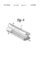
- FIG. 4 is a perspective view of an end of another extruded weather strip from which a tubular seal portion is cut-off.
- the present invention will be explained based on an embodiment wherein a weather strip, adapted to be attached along a side of a roof around door openings of a motor vehicle, is produced.
- FIGS. 3(A) to 3(C) show an end portion of a weather strip W produced by the method in accordance with the present invention.
- an extruded weather strip 28 including a base portion 24 composed of solid rubber and a tubular seal portion 26 composed of sponge rubber is prepared, and, as shown in FIG. 3(D), only a portion of the tubular seal portion 26 is cut-off at a predetermined length at the end of the prepared extruded weather strip 28 with the base portion 24a thereof remaining uncut.
- the uncut base portion 24a of the end of the extruded weather strip 28 is placed in a cavity 32 of a mold 30.
- the mold 30 is composed of a lower mold member 30A, upper mold member 30B, intermediate mold members 30C and 30D which define the cavity 32.
- the cavity 32 defines a molding chamber for molding a tubular part 34 (FIG. 3(A)), which has a cross-section identical to that of the tubular seal portion 26 of the extruded weather strip 28, and a second molding chamber (not shown) for molding a fin-like end part 40 (FIG. 3(A)).
- the second molding chamber has a configuration capable of forming in a reverse face of the fin-like part 40, a depression 36 having great width, which interconnects with an end opening 35 of the tubular part 34, and a plurality of small depressions 38 separated from each other.
- the tubular part 34 having a cross-section identical to that of the tubular seal portion 26 of the extruded weather strip 28, and the fin-like end part 40 which extends continuously from the tubular part 34 are formed integrally with the end of the extruded weather strip 28.
- the mold is opened and the molded end portion is removed from the mold.
- the core 42 disposed within the molded tubular part 34, is removed through the end opening 35 by drawing the core 42 along the depression 36 formed in the reverse face of the molded end part 40, and pulling it obliquely downwards.
- the uncut base portion 24a is composed of an extruded body of solid rubber so that the surface slidability thereof is good so as to facilitate the removal of the core 42.
- the molded tubular part 34 is expanded to facilitate the removal of the core 42 further.
- a molded end portion is formed onto an end of an extruded weather strip having a tubular configuration
- the present invention is also applicable to other weather strips with different configurations.
- an extruded weather strip 44 includes a base portion 46, a tubular seal portion 48 and a lip-like seal portion 50. Only a portion of the tubular seal portion 48 is cut-off from an end of the extruded weather strip 44. The formation of a molded end portion and removal of a core are respectively performed similarly to that of the preceding embodiment.
- an end portion can be integrally molded onto an end of a weather strip having a tubular seal portion without removing a core through a core-removing opening therein.
- the weather strip obtained by the method of the present invention exhibits good attaching stability when attached to a retainer, because the resultant weather strip has no core-removing opening.
- there is no need for the closing operation of the core-removing opening which eliminates the operations of removing flashes and closing the core-removing opening, which reduces production steps and thus production costs.
Abstract
Description
Claims (4)
Applications Claiming Priority (2)
| Application Number | Priority Date | Filing Date | Title |
|---|---|---|---|
| JP7-58099 | 1995-02-22 | ||
| JP05809995A JP3467896B2 (en) | 1995-02-22 | 1995-02-22 | Manufacturing method of weather strip for automobile |
Publications (1)
| Publication Number | Publication Date |
|---|---|
| US5711907A true US5711907A (en) | 1998-01-27 |
Family
ID=13074516
Family Applications (1)
| Application Number | Title | Priority Date | Filing Date |
|---|---|---|---|
| US08/602,446 Expired - Fee Related US5711907A (en) | 1995-02-22 | 1996-02-16 | Method for producing a weather strip for a motor vehicle |
Country Status (2)
| Country | Link |
|---|---|
| US (1) | US5711907A (en) |
| JP (1) | JP3467896B2 (en) |
Cited By (13)
| Publication number | Priority date | Publication date | Assignee | Title |
|---|---|---|---|---|
| US5972268A (en) * | 1997-11-06 | 1999-10-26 | Toyoda Gosei Co., Ltd. | Method of forming a corner part of a weather strip |
| US6007753A (en) * | 1997-04-10 | 1999-12-28 | Toyoda Gosei Co., Ltd. | Method for processing an end portion of a weather strip |
| US6623688B2 (en) | 2001-06-28 | 2003-09-23 | Cascade Engineering, Inc. | Gas-assisted two-shot injection molding process |
| US20030188491A1 (en) * | 1999-07-23 | 2003-10-09 | Masanori Aritake | Process for manufacturing weather strip |
| US6748702B2 (en) | 2002-06-11 | 2004-06-15 | Hyundai Motor Company | Outside weather strip of a vehicle |
| US20040247827A1 (en) * | 2003-03-28 | 2004-12-09 | Yoshihisa Kubo | Weather strip and manufacturing method therefor |
| US20040250474A1 (en) * | 2003-03-28 | 2004-12-16 | Yoshihisa Kubo | Weather strip |
| US6866811B2 (en) | 2000-04-28 | 2005-03-15 | Mitsubishi Engineering-Plastics Corp. | Method for injection-molding an article having a hollow portion |
| US20050208232A1 (en) * | 2004-03-19 | 2005-09-22 | Nobuyuki Kimura | Weather strip and method of manufacturing the same |
| WO2009012570A1 (en) * | 2007-07-24 | 2009-01-29 | Magna International Inc. | Outer belt polypropylene endcap insert function partially as material mold tooling shut-off |
| US20130142990A1 (en) * | 2010-07-08 | 2013-06-06 | Tokai Kogyo Co., Ltd. | Composite molded article and manufacturing method thereof |
| US10752184B2 (en) | 2015-06-19 | 2020-08-25 | Henniges Automotive Sealing Systems North America, Inc. | Trim strip assembly for vehicle and method of manufacturing same |
| US11148615B2 (en) | 2015-06-19 | 2021-10-19 | Henniges Automotive Sealing Systems North America, Inc. | Fixed window assembly for a vehicle and method of manufacturing same |
Families Citing this family (5)
| Publication number | Priority date | Publication date | Assignee | Title |
|---|---|---|---|---|
| JP3797522B2 (en) * | 1998-07-10 | 2006-07-19 | 西川ゴム工業株式会社 | Door and glass run |
| JP4873240B2 (en) * | 2006-10-30 | 2012-02-08 | 豊田合成株式会社 | Weather strip for automobile |
| JP5190208B2 (en) * | 2007-03-07 | 2013-04-24 | 鬼怒川ゴム工業株式会社 | Weather strip for automobile |
| JP5829481B2 (en) * | 2011-10-26 | 2015-12-09 | 西川ゴム工業株式会社 | Weather Strip |
| CN114474818B (en) * | 2022-02-23 | 2022-11-18 | 山东水星博惠汽车部件股份有限公司 | Core taking machine and core taking method for automobile composite sealing strip |
Citations (10)
| Publication number | Priority date | Publication date | Assignee | Title |
|---|---|---|---|---|
| JPS5922735A (en) * | 1982-07-30 | 1984-02-06 | Hashimoto Forming Co Ltd | Molding of end cap of extruded synthetic resin braid |
| JPS5967035A (en) * | 1982-10-08 | 1984-04-16 | Kinugawa Rubber Ind Co Ltd | Forming method of corner part of rubber made glass running channel |
| US4620959A (en) * | 1983-02-25 | 1986-11-04 | Ngk Insulators, Ltd. | Method of releasing an inner mold from a rubbery elastic molding |
| US4719067A (en) * | 1984-06-05 | 1988-01-12 | Gebr. Happich Gmbh | Method and apparatus for forming end pieces on plastic molding strips |
| US4861530A (en) * | 1987-06-05 | 1989-08-29 | S.A.I.A.G. S.P.A. | Method for enabling the cutting to size of a continuously extruded weather strip with variable characteristics, particularly for motor vehicle bodies |
| JPH02297569A (en) * | 1989-05-12 | 1990-12-10 | Casio Comput Co Ltd | Electrostatic recorder |
| US4986947A (en) * | 1989-06-29 | 1991-01-22 | Toyoda Gosei Co., Ltd. | Method for connecting ends of weather strips |
| JPH03290714A (en) * | 1990-04-06 | 1991-12-20 | Mitsubishi Electric Corp | Method and device for control of servo motor |
| US5395579A (en) * | 1992-02-28 | 1995-03-07 | Kinugawa Rubber Ind. Co., Ltd. | Method of producing weatherstrip for automotive vehicle |
| US5494630A (en) * | 1994-07-01 | 1996-02-27 | The Standard Products Company | Method of forming molding end |
-
1995
- 1995-02-22 JP JP05809995A patent/JP3467896B2/en not_active Expired - Fee Related
-
1996
- 1996-02-16 US US08/602,446 patent/US5711907A/en not_active Expired - Fee Related
Patent Citations (10)
| Publication number | Priority date | Publication date | Assignee | Title |
|---|---|---|---|---|
| JPS5922735A (en) * | 1982-07-30 | 1984-02-06 | Hashimoto Forming Co Ltd | Molding of end cap of extruded synthetic resin braid |
| JPS5967035A (en) * | 1982-10-08 | 1984-04-16 | Kinugawa Rubber Ind Co Ltd | Forming method of corner part of rubber made glass running channel |
| US4620959A (en) * | 1983-02-25 | 1986-11-04 | Ngk Insulators, Ltd. | Method of releasing an inner mold from a rubbery elastic molding |
| US4719067A (en) * | 1984-06-05 | 1988-01-12 | Gebr. Happich Gmbh | Method and apparatus for forming end pieces on plastic molding strips |
| US4861530A (en) * | 1987-06-05 | 1989-08-29 | S.A.I.A.G. S.P.A. | Method for enabling the cutting to size of a continuously extruded weather strip with variable characteristics, particularly for motor vehicle bodies |
| JPH02297569A (en) * | 1989-05-12 | 1990-12-10 | Casio Comput Co Ltd | Electrostatic recorder |
| US4986947A (en) * | 1989-06-29 | 1991-01-22 | Toyoda Gosei Co., Ltd. | Method for connecting ends of weather strips |
| JPH03290714A (en) * | 1990-04-06 | 1991-12-20 | Mitsubishi Electric Corp | Method and device for control of servo motor |
| US5395579A (en) * | 1992-02-28 | 1995-03-07 | Kinugawa Rubber Ind. Co., Ltd. | Method of producing weatherstrip for automotive vehicle |
| US5494630A (en) * | 1994-07-01 | 1996-02-27 | The Standard Products Company | Method of forming molding end |
Cited By (22)
| Publication number | Priority date | Publication date | Assignee | Title |
|---|---|---|---|---|
| US6007753A (en) * | 1997-04-10 | 1999-12-28 | Toyoda Gosei Co., Ltd. | Method for processing an end portion of a weather strip |
| US5972268A (en) * | 1997-11-06 | 1999-10-26 | Toyoda Gosei Co., Ltd. | Method of forming a corner part of a weather strip |
| US20030188491A1 (en) * | 1999-07-23 | 2003-10-09 | Masanori Aritake | Process for manufacturing weather strip |
| US6786007B2 (en) * | 1999-07-23 | 2004-09-07 | Toyoda Gosei Co, Ltd. | Process for manufacturing weather strip |
| US6866811B2 (en) | 2000-04-28 | 2005-03-15 | Mitsubishi Engineering-Plastics Corp. | Method for injection-molding an article having a hollow portion |
| US6623688B2 (en) | 2001-06-28 | 2003-09-23 | Cascade Engineering, Inc. | Gas-assisted two-shot injection molding process |
| US20030206985A1 (en) * | 2001-06-28 | 2003-11-06 | Cascade Engineering, Inc. | Gas-assisted two-shot injection molding process |
| US6748702B2 (en) | 2002-06-11 | 2004-06-15 | Hyundai Motor Company | Outside weather strip of a vehicle |
| US7247362B2 (en) | 2003-03-28 | 2007-07-24 | Toyoda Gosei Co., Ltd. | Weather strip |
| US20040247827A1 (en) * | 2003-03-28 | 2004-12-09 | Yoshihisa Kubo | Weather strip and manufacturing method therefor |
| US20040250474A1 (en) * | 2003-03-28 | 2004-12-16 | Yoshihisa Kubo | Weather strip |
| US7214417B2 (en) | 2003-03-28 | 2007-05-08 | Toyoda Gosei Co., Ltd. | Weather strip and manufacturing method therefor |
| US20050208232A1 (en) * | 2004-03-19 | 2005-09-22 | Nobuyuki Kimura | Weather strip and method of manufacturing the same |
| WO2009012570A1 (en) * | 2007-07-24 | 2009-01-29 | Magna International Inc. | Outer belt polypropylene endcap insert function partially as material mold tooling shut-off |
| US20090025300A1 (en) * | 2007-07-24 | 2009-01-29 | Ho Toan C | Outer belt polypropylene encap insert function partially as material mold tooling shut-off |
| US8001727B2 (en) | 2007-07-24 | 2011-08-23 | Magna International Inc | Sealing molding with insert for forming closeout surface |
| US20110266716A1 (en) * | 2007-07-24 | 2011-11-03 | Magna International Inc. | Sealing Molding With Insert For Forming Closeout Surface |
| US20130142990A1 (en) * | 2010-07-08 | 2013-06-06 | Tokai Kogyo Co., Ltd. | Composite molded article and manufacturing method thereof |
| US9073286B2 (en) * | 2010-07-08 | 2015-07-07 | Tokai Kogyo Co., Ltd. | Composite molded article and manufacturing method thereof |
| US10752184B2 (en) | 2015-06-19 | 2020-08-25 | Henniges Automotive Sealing Systems North America, Inc. | Trim strip assembly for vehicle and method of manufacturing same |
| US11148615B2 (en) | 2015-06-19 | 2021-10-19 | Henniges Automotive Sealing Systems North America, Inc. | Fixed window assembly for a vehicle and method of manufacturing same |
| US11173852B2 (en) * | 2015-06-19 | 2021-11-16 | Henniges Automotive Sealing Systems North America, Inc. | Method of manufacturing decorative trim |
Also Published As
| Publication number | Publication date |
|---|---|
| JPH08224764A (en) | 1996-09-03 |
| JP3467896B2 (en) | 2003-11-17 |
Similar Documents
| Publication | Publication Date | Title |
|---|---|---|
| US5711907A (en) | Method for producing a weather strip for a motor vehicle | |
| JPH0736845Y2 (en) | Automotive weather strip connection structure | |
| US5566510A (en) | Molded glass run channel corner assembly | |
| US4769947A (en) | Weather strip for automobile | |
| US5972268A (en) | Method of forming a corner part of a weather strip | |
| CA2013681C (en) | Method for connecting ends of weather strips | |
| CA2042747C (en) | Door glass run for motor vehicle | |
| JP3814946B2 (en) | Method for forming corner part of door glass run for automobile | |
| US5819472A (en) | Method and article of manufacture for reinforcing curved sections of hollow weatherstrip material | |
| JP2572144B2 (en) | Automotive weather strip | |
| JP2005186543A (en) | Manufacturing method for weather strip and mold for weather strip | |
| JPH05139217A (en) | Weatherstrip for automobile | |
| JPH0125686B2 (en) | ||
| JPH0755165Y2 (en) | Automotive weather strip | |
| JP2674363B2 (en) | Method of molding weather strip mold connection | |
| JPH07115589B2 (en) | Automotive weather strip | |
| JPS6194815A (en) | Weather strip having drain and manufacture thereof | |
| JP4274676B2 (en) | Weather strip | |
| JP2924226B2 (en) | Automotive glass run | |
| JP3201857B2 (en) | Weatherstrip mounting structure for sashless door type car | |
| JPS63290714A (en) | Corner molding method for weather strip for automobile | |
| JP3740563B2 (en) | Weather strip manufacturing method | |
| JPH0986175A (en) | Weather strip connecting structure | |
| JP3427635B2 (en) | Weather strip mold connection method | |
| JPH11227544A (en) | Weather strip for car and its manufacture |
Legal Events
| Date | Code | Title | Description |
|---|---|---|---|
| AS | Assignment |
Owner name: TOYODA GOSEI CO., LTD., JAPAN Free format text: ASSIGNMENT OF ASSIGNORS INTEREST;ASSIGNORS:NOZAKI, MASAHIRO;NAGATA, TATSUHIKO;REEL/FRAME:007861/0470 Effective date: 19960202 |
|
| FEPP | Fee payment procedure |
Free format text: PAYOR NUMBER ASSIGNED (ORIGINAL EVENT CODE: ASPN); ENTITY STATUS OF PATENT OWNER: LARGE ENTITY |
|
| FPAY | Fee payment |
Year of fee payment: 4 |
|
| FPAY | Fee payment |
Year of fee payment: 8 |
|
| FEPP | Fee payment procedure |
Free format text: PAYER NUMBER DE-ASSIGNED (ORIGINAL EVENT CODE: RMPN); ENTITY STATUS OF PATENT OWNER: LARGE ENTITY Free format text: PAYOR NUMBER ASSIGNED (ORIGINAL EVENT CODE: ASPN); ENTITY STATUS OF PATENT OWNER: LARGE ENTITY |
|
| REMI | Maintenance fee reminder mailed | ||
| LAPS | Lapse for failure to pay maintenance fees | ||
| STCH | Information on status: patent discontinuation |
Free format text: PATENT EXPIRED DUE TO NONPAYMENT OF MAINTENANCE FEES UNDER 37 CFR 1.362 |
|
| FP | Lapsed due to failure to pay maintenance fee |
Effective date: 20100127 |