US5718258A - Releasing additives into engine oil - Google Patents
Releasing additives into engine oil Download PDFInfo
- Publication number
- US5718258A US5718258A US08/740,139 US74013996A US5718258A US 5718258 A US5718258 A US 5718258A US 74013996 A US74013996 A US 74013996A US 5718258 A US5718258 A US 5718258A
- Authority
- US
- United States
- Prior art keywords
- canister
- container
- recited
- oil
- outlet
- Prior art date
- Legal status (The legal status is an assumption and is not a legal conclusion. Google has not performed a legal analysis and makes no representation as to the accuracy of the status listed.)
- Expired - Lifetime
Links
Images
Classifications
-
- B—PERFORMING OPERATIONS; TRANSPORTING
- B01—PHYSICAL OR CHEMICAL PROCESSES OR APPARATUS IN GENERAL
- B01F—MIXING, e.g. DISSOLVING, EMULSIFYING OR DISPERSING
- B01F21/00—Dissolving
- B01F21/20—Dissolving using flow mixing
- B01F21/22—Dissolving using flow mixing using additional holders in conduits, containers or pools for keeping the solid material in place, e.g. supports or receptacles
- B01F21/221—Dissolving using flow mixing using additional holders in conduits, containers or pools for keeping the solid material in place, e.g. supports or receptacles comprising constructions for blocking or redispersing undissolved solids
-
- B—PERFORMING OPERATIONS; TRANSPORTING
- B01—PHYSICAL OR CHEMICAL PROCESSES OR APPARATUS IN GENERAL
- B01D—SEPARATION
- B01D37/00—Processes of filtration
- B01D37/02—Precoating the filter medium; Addition of filter aids to the liquid being filtered
- B01D37/025—Precoating the filter medium; Addition of filter aids to the liquid being filtered additives incorporated in the filter
-
- C—CHEMISTRY; METALLURGY
- C10—PETROLEUM, GAS OR COKE INDUSTRIES; TECHNICAL GASES CONTAINING CARBON MONOXIDE; FUELS; LUBRICANTS; PEAT
- C10M—LUBRICATING COMPOSITIONS; USE OF CHEMICAL SUBSTANCES EITHER ALONE OR AS LUBRICATING INGREDIENTS IN A LUBRICATING COMPOSITION
- C10M175/00—Working-up used lubricants to recover useful products ; Cleaning
- C10M175/0091—Treatment of oils in a continuous lubricating circuit (e.g. motor oil system)
-
- Y—GENERAL TAGGING OF NEW TECHNOLOGICAL DEVELOPMENTS; GENERAL TAGGING OF CROSS-SECTIONAL TECHNOLOGIES SPANNING OVER SEVERAL SECTIONS OF THE IPC; TECHNICAL SUBJECTS COVERED BY FORMER USPC CROSS-REFERENCE ART COLLECTIONS [XRACs] AND DIGESTS
- Y10—TECHNICAL SUBJECTS COVERED BY FORMER USPC
- Y10T—TECHNICAL SUBJECTS COVERED BY FORMER US CLASSIFICATION
- Y10T137/00—Fluid handling
- Y10T137/4891—With holder for solid, flaky or pulverized material to be dissolved or entrained
Definitions
- thermoplastic polymers having additives--such as anti-oxidants--incorporated therein in order to extend the time between oil filter changes and/or adequately protect the invention. Examples of these techniques are shown in U.S. Pat. Nos. 4,066,559 and 4,144,166, the disclosures of which are hereby incorporated by reference herein.
- thermoplastic material gradually dissolves in above ambient temperature oil (e.g. about 150° F. or higher), the thermoplastic having oil property improving additives which are released into the oil over time as the thermoplastic material dissolves.
- the discrete shapes e.g. the shape of pellets, such as rice-shaped pellets or strands
- a canister for releasing oil additives into oil in an internal combustion engine, hydraulic equipment, or automatic transmissions comprises the following components: A container having an inlet, an outlet, and an interior volume between the inlet and outlet. Partitions dividing the interior volume into a plurality of different individual compartments. A plurality of discrete shapes of thermoplastic material which gradually dissolves in above ambient temperature oil, the thermoplastic material having oil properties improving additives which are released into the oil over time as the thermoplastic material dissolves. And, the discrete shapes disposed within at least a plurality of the different individual compartments.
- the partitions may comprise a metal grid (e.g. 16 gauge steel) and the discrete shapes are disposed in substantially all of the individual compartments.
- a container may have first and second perforated end faces which contain the inlet and outlet respectively, and the container may be substantially disc-shaped, having a circumferential wall that is approximately 1/8 to 1/2 inch long, and so that the entire thickness of the container is about 1/8-1/2 inch (e.g. about 1/4 inch).
- the first end face may have a flexible material seal surrounding the inlet which can seal with the oil block of an internal combustion engine.
- the container may further comprise a central opening larger than the perforation openings in each end wall in alignment with each other, and there is further provided an interior wall extending between the central openings to provide a central oil flow passage distinct from the oil flow through the perforation openings.
- An O-ring may be provided surrounding each of the central openings to seal the container to the engine block and an oil filter.
- the container may be provided in combination with an oil filter and engine block, the container disposed between the oil filter and engine block and the engine block having an exteriorly threaded tube which extends through the central openings and engages the oil filter.
- the container may comprise first and second parts, each having a perforated end wall and a circumferential wall, the first part circumferential wall having a larger diameter than the second part circumferential wall so that the circumferential walls are concentric, and a sealant (such as a flexible Plastasol type sealant) may seal the parts together.
- the discrete shape additives may include an anti-oxidant, acid neutralizer, anti-foaming agent, detergent, viscosity enhancer, or combinations thereof.
- the container may comprise an elongated tube having first and second end faces, and a circumferential wall having a length of more than one inch (typically several inches) in the dimension of elongation of the tube, the inlet in the first face and the outlet in the second face.
- the partitions may comprise disc-shaped elements each extending in a plane substantially transverse to the dimension of elongation, the elements having a plurality of openings therein shaped and dimensioned with respect to the discrete shapes so that the discrete shapes cannot pass through the openings in the elements.
- the individual volumes are less than filled with the discrete shapes (e.g. about 40-80% filled) so that oil flowing through the container will agitate and flow around the discrete shapes for optimum additive release.
- a check valve connected to the outlet to preclude reverse flow of oil into the outlet.
- the inlet typically includes a metering jet for limiting the flow rate through the container while a screen is disposed at the outlet.
- the individual compartments typically include an end compartment adjacent the second face, the end compartment preferably being devoid of the discrete shapes.
- the inlet is typically connected to an engine block and the outlet is connected to an oil filter.
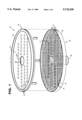
- FIG. 1 is a perspective exploded view of one exemplary embodiment of a canister for releasing oil additives into oil;
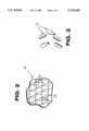
- FIG. 2 is a detail perspective view of a metal grid that may be used in the construction of FIG. 1;
- FIG. 3 is an enlarged perspective view of one exemplary geometric configuration that the thermoplastic material discrete shapes according to the invention may take;
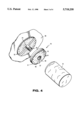
- FIG. 4 is a perspective exploded view showing the container of FIG. 1 in association with an engine block and a conventional oil filter;
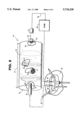
- FIG. 5 is a perspective view, with portions of the casing cut away for clarity of illustration, of a second embodiment of a container according to the present invention shown schematically in association with an engine block and oil filter.
- FIGS. 1 through 4 illustrate one exemplary embodiment of a canister for releasing oil additives into oil in an internal combustion engine, hydraulic equipment, automatic transmissions, or the like, according to the present invention.
- the canister is shown generally by reference numeral 10 and includes an inlet, outlet, and an interior volume, the interior volume shown generally by reference numeral 11 in FIG. 1.
- the container has a generally disc shape with a total thickness of approximately 1/8 to 1/2 inch (e.g. about 1/4 inch).
- the inlet comprises a first end face 12 with a plurality of perforation openings 13 therein.
- the outlet includes perforation openings 14 in the second end face 15.
- the container 10 also has a circumferential wall 16 with a total thickness 17 (e.g. approximately 1/8 to 1/2 inch) so that the container 10 may fit appropriately in association with a conventional oil filter on an engine block.
- the container 10 is formed in two parts shown generally by reference numerals 18 and 19.
- the first part 18 circumferential wall 16 has a slightly larger diameter than the second part circumferential wall 20 so that the part 18 overlaps the part 19. Then the entire periphery of the circumferential wall 16 may be sealed to the circumferential wall 20 with any suitable sealing component, such as a flexible Plastisol type sealant, shown generally by reference numeral 21 in FIG. 4.
- the embodiment shown in FIGS. 1 through 10 also includes a partition dividing the interior volume 11 into a plurality of different individual compartments.
- the partition takes the form of a metal grid, shown schematically and in general by reference numeral 23 in FIG. 2.
- the grid 23 may be constructed of 16 gauge steel, and the individual compartments 24 are rectangular or square in configuration.
- the grid has approximately the same height 25 as the height of the circumferential wall 20, and prevents the ends 12, 15 from collapsing, providing rigidity to the entire container 10.
- the container 10 also includes a plurality of discrete shapes, such as the pellets shown generally by reference numeral 27 in FIG. 3, disposed within the individual compartments 24, a plurality of the discrete shapes 27 disposed within substantially each of the compartments 24 in the preferred embodiment.
- the discrete shapes may include a variety of different configurations, such as strands, cubes, spheres, or--as illustrated in FIG. 3--rice-shaped pellets (disclosed and described in detail in said co-pending application). While a wide variety of different materials may be provided, the thermoplastic material discrete shapes 27 may comprise about 83-90% all percentages indicated herein are weight %! liquid ethylene propylene, and about 10-17% dispersing agent, lubricant, and detergent neutralizer combined.
- additives provided in the polypropylene may comprise about 3-5% dispersing agent, about 1-1.5% organic phosphate lubricant, about 2.5-3.5% detergent neutralizing sulfonate, and about 4.5-5.5% detergent neutralizing phenate.
- ethylene propylene in liquid form may comprise 86.8 parts, Cooper E-644 dispersing agent 4.0 parts, Cooper E-685 zinc organic phosphate lubricant 1.2 parts, Cooper E-654 detergent neutralizing sulfonate 3.0 parts, and Cooper M-6148 detergent neutralizing phenate 5.0 parts.
- the anti-oxidation and acidification additives are mixed with the liquid thermoplastic material to form a thermoplastic mixture.
- the mixture is extruded, utilizing a conventional extruder, into spaghetti-like strands having a thickness of about 0.0625-0.125 inches. Then the strands are cooled, as in a cooling trough, and cut, as by using a conventional chopper, into discrete elements 27. That is the discrete shapes additives may include an anti-oxidant, acid neutralizer, anti-foaming agent, detergent, viscosity enhancer, or combinations thereof.
- the grid 23 also provides support for the canister end faces 12, 15 to give rigidity to the entire container 10.
- the container 10 is disposed between the engine block 30 and a conventional oil filter 31, the perforation openings 13 communicating with cooperating openings 32 or the like in the engine block.
- the engine block as is conventional, has an exteriorly threaded (see 33) tube 34 extending outwardly therefrom, threads 33 being received by internal threads at the end of the oil filter 31.
- the container 10 includes a central opening 36, 37, respectively, in each of the end faces 12, 15 which is larger than the perforation openings 13 and are in alignment with each other, and an interior tubular wall 38 extending between the central openings 36, 37 to provide a central oil flow passage distinct from the oil flow through the perforation openings 13, 14.
- an O-ring such as the O-ring 39, 40 (typically of nitril rubber having a diameter of the rubber material itself of about 1/8 inch), or a like sealing component, is provided to seal the central passage defined by the tubular wall 38.
- the perforation openings 13, 14 are positioned with respect to the partition 23 walls 24, and are dimensioned with respect the partition 23 and the discrete shapes 27 so that the discrete shapes 27 cannot pass through the perforation openings 13, 14.
- the appropriate additives from the shapes 27 are released into the oil typically when the temperature thereof reaches a 150° F. or above and the thermoplastic material providing the bulk of the shapes 27 gradually dissolves.
- the container 10 is periodically replaced based upon TBN levels in a periodic oil analysis report, and typically is replaced less frequently than the filter 31.
- a second exemplary embodiment according to the present invention is illustrated schematically by reference numeral 45 in FIG. 5 in which the configuration of the container, partitions, inlet, and outlet are significantly different than the embodiment of FIGS. 1 and 4.
- the container 45 comprises an elongated tubular casing 46, which has a length 47 in the dimension of elongation thereof which is greater than an inch, and preferably several inches.
- the container 45 also has first and second end walls 48, 49 which have an inlet 50 and an outlet 51, respectively, therein.
- the partitions comprise a plurality of disc-shaped elements 51 each extending in a plane substantially traverse to the dimension of elongation 47 of the container circumferential wall 46, and generally parallel to each other.
- Each of the elements 51 has a plurality of openings 52 therein shaped and dimensioned with respect to the discrete shapes 27 so that the discrete shapes 27 cannot pass through the openings 52.
- the individual volumes 54 between the disc-shaped elements 51 and the end faces 48, 49, respectively, are less than completely filled with the discrete shapes 27 (e.g. typically only about 40-80% filled).
- the plurality of shapes 27 are provided in sufficient volume within the compartments 54 so that oil flowing through the container 45 will agitate and flow around the discrete shapes 27 for optimum additive release.
- the oil is introduced in container 45 inlet 50 through a metering jet 55 which reduces the flow rate of the oil.
- a metering jet 55 which reduces the flow rate of the oil.
- the metering jet 55 which has an opening perhaps 1/32 to 1/64 inch in dimension! restricts the flow through the filter 56 at the normal rate through the oil filter 56.
- the oil filter 56 traps many solids and the differential pressure starts to increase across the inlet and outlet sides of container 45 due to the increased resistance of flow caused by the build-up of contaminants.
- the increase in differential pressure causes the flow rate to increase through the container 45 allowing more of the hot oil to pass through the canister 45 thus increasing the additives in the container 47 shapes 27. This increase compensates for the additive depletion occurring in the oil as the additives normally present in the oil are consumed.
- a check valve 57 is disposed in the outlet 51 (the check valve 57 of any conventional construction such as a spring pressed ball) to prevent any backflow of oil into the container 45.
- the check valve 57 of any conventional construction such as a spring pressed ball
- the container 45 keeps the additives in the oil at or near the new oil additive level.
- the last of the compartments 54, containing the outlet 51 preferably is left devoid of shapes 27 so that they cannot clog the opening 51. Also a screen 58 is preferably provided at the outlet 51 in the last compartment 54.
- any suitable connection may be provided between the container 45 and the filter 56 on the engine block 59.
- the outlet 60 from the engine block 59 is connected to the inlet 50 via any suitable conventional fitting 61, for example a 3/16 inch interior diameter fitting, such as a conventional swivel flared fitting to make it easy to service the additive canister 45.
- the inlet 62 back to the engine block 59 is connected to the filter 56 and the outlet 51 and/or check valve 57 by similar pipes and fittings illustrated schematically by 63 in FIG. 5.
- the container 45 may be constructed so that it is disposable, that is once the additive value of the shapes 27 therein have been exhausted the container 45 is replaced, or the container 45 may be constructed so that it is refillable. If refillable the container 45 may be constructed so that one or both of the end faces 48, 49 are connected to a rack, which is similarly connected to the disc-shaped elements 51 so that end faces 48, and/or 49 and the elements 51 are removable from the circumferential housing 46 and the old, spent, shapes 27 may be discharged and new shapes 27 put in their place.
- a canister for releasing oil additives into oil which provides a plurality of individual compartments containing discrete shapes which the oil flows around and gradually dissolves to release the appropriate additives into the oil.
Abstract
Description
Claims (20)
Priority Applications (1)
| Application Number | Priority Date | Filing Date | Title |
|---|---|---|---|
| US08/740,139 US5718258A (en) | 1996-10-22 | 1996-10-22 | Releasing additives into engine oil |
Applications Claiming Priority (1)
| Application Number | Priority Date | Filing Date | Title |
|---|---|---|---|
| US08/740,139 US5718258A (en) | 1996-10-22 | 1996-10-22 | Releasing additives into engine oil |
Publications (1)
| Publication Number | Publication Date |
|---|---|
| US5718258A true US5718258A (en) | 1998-02-17 |
Family
ID=24975208
Family Applications (1)
| Application Number | Title | Priority Date | Filing Date |
|---|---|---|---|
| US08/740,139 Expired - Lifetime US5718258A (en) | 1996-10-22 | 1996-10-22 | Releasing additives into engine oil |
Country Status (1)
| Country | Link |
|---|---|
| US (1) | US5718258A (en) |
Cited By (44)
| Publication number | Priority date | Publication date | Assignee | Title |
|---|---|---|---|---|
| EP0889115A2 (en) * | 1997-07-03 | 1999-01-07 | Toyota Jidosha Kabushiki Kaisha | An engine oil deterioration preventing agent and device |
| US20020014447A1 (en) * | 2000-05-08 | 2002-02-07 | Rohrbach Ronald Paul | Staged oil filter incorporating additive-releasing particles |
| US20020043495A1 (en) * | 2000-01-19 | 2002-04-18 | Beard John H. | Combination particulate and acid-neutralizing filter |
| WO2002092192A1 (en) * | 2001-05-17 | 2002-11-21 | Beard John H | Acid-neutralizing filter |
| US20030069378A1 (en) * | 2000-04-28 | 2003-04-10 | Sanduja Mohan L. | Filtration efficiency |
| US20030226793A1 (en) * | 2002-06-07 | 2003-12-11 | Baldwin Filters, Inc. | Environmentally friendly acid neutralizing full flow cartridge |
| US20040014614A1 (en) * | 2002-07-16 | 2004-01-22 | Burrington James D. | Slow release lubricant additives gel |
| GB2392395A (en) * | 2001-05-17 | 2004-03-03 | D A Lubricant Company Inc | Acid-neutralizing filter |
| WO2004020070A1 (en) * | 2002-08-30 | 2004-03-11 | Honeywell International Inc. | Staged oil filter incorporating timed release oil conditioner |
| US20040079589A1 (en) * | 2002-10-23 | 2004-04-29 | Schneider Eric West | Automatic additive replenishment system for IC engine lubricating oil |
| US20040140255A1 (en) * | 2002-06-07 | 2004-07-22 | Baldwin Filters, Inc. | Environmentally friendly acid neutralizing cartridge |
| US20040140254A1 (en) * | 2002-06-07 | 2004-07-22 | Merritt Steven J. | Acid neutralizing filter canister |
| US20040154970A1 (en) * | 2000-05-08 | 2004-08-12 | Rohrbach Ronald Paul | Staged oil filter incorporating pelletized basic conditioner |
| US20040159304A1 (en) * | 2003-02-14 | 2004-08-19 | Frank Caracciolo | Additive-containing, dissolvable coating on engine part that contacts oil |
| US20040266631A1 (en) * | 2003-06-25 | 2004-12-30 | The Lubrizol Corporation | Gels that reduce soot and/or emissions from engines |
| US20050019236A1 (en) * | 2001-08-24 | 2005-01-27 | Harold Martin | Controlled release of additives in fluid systems |
| US20050137097A1 (en) * | 2002-07-16 | 2005-06-23 | The Lubrizol Corporation | Controlled release of additive gel(s) for functional fluids |
| US20050173325A1 (en) * | 2004-01-13 | 2005-08-11 | Mann & Hummel Gmbh | Additive dispensing filter apparatus |
| US20050194301A1 (en) * | 2004-03-05 | 2005-09-08 | Hacker John R. | Liquid filter assembly for use with treatment agent; and, methods |
| US7000655B2 (en) | 2004-01-09 | 2006-02-21 | The Lubrizol Corporation | Fluid additive delivery systems |
| US7018531B2 (en) | 2001-05-30 | 2006-03-28 | Honeywell International Inc. | Additive dispensing cartridge for an oil filter, and oil filter incorporating same |
| US7182863B2 (en) | 2000-05-08 | 2007-02-27 | Honeywell International, Inc. | Additive dispersing filter and method of making |
| US20070235378A1 (en) * | 2004-03-05 | 2007-10-11 | Donaldson Corporation Company, Inc. | Top Load Liquid Filter Assembly for Use with Treatment Agent; and, Methods |
| US20080047887A1 (en) * | 2006-08-28 | 2008-02-28 | Gerwin Weston H | Additive dispersing filter and method of making |
| US20080188386A1 (en) * | 2007-02-05 | 2008-08-07 | The Lubrizol Corporation | Low Ash Controlled Release Gels |
| US20090050547A1 (en) * | 2007-06-14 | 2009-02-26 | Hsu Jeffery Hsiu | Additive Releasing Oil Filter |
| US20090064646A1 (en) * | 2004-08-06 | 2009-03-12 | Donaldson Company, Inc. | Air filter arrangement; assembly; and methods |
| US20090139483A1 (en) * | 2005-05-20 | 2009-06-04 | Lutek, Llc | Materials and processes for reducing combustion by-products in a lubrication system for an internal combustion engine |
| US20090151311A1 (en) * | 2005-01-13 | 2009-06-18 | Donaldson Company, Inc. | Air filter cartridge and air cleaner assembly |
| US20090206024A1 (en) * | 2008-02-15 | 2009-08-20 | Bilski Gerard W | Additive dispensing device and a thermally activated additive dispensing filter having the additive dispensing device |
| US7625419B2 (en) | 2006-05-10 | 2009-12-01 | Donaldson Company, Inc. | Air filter arrangement; assembly; and, methods |
| US20100108018A1 (en) * | 2006-06-21 | 2010-05-06 | Castrol Limited | Apparatus and method for adding one or more additives to an engine lubricant |
| US8034145B2 (en) | 2004-06-14 | 2011-10-11 | Donaldson Company, Inc. | Air filter arrangement; assembly; and, methods |
| US8293119B2 (en) | 2007-10-19 | 2012-10-23 | The Lubrizol Corporation | Filter cap additive delivery system |
| US8425772B2 (en) | 2006-12-12 | 2013-04-23 | Cummins Filtration Ip, Inc. | Filtration device with releasable additive |
| US8496723B2 (en) | 2005-01-13 | 2013-07-30 | Donaldson Company, Inc. | Air filter arrangement |
| US20140251883A1 (en) * | 2011-11-07 | 2014-09-11 | Toyota Jidosha Kabushiki Kaisha | OIL DETERIORATION PREVENTION DEVICE (as amended) |
| US9555370B2 (en) | 2007-09-07 | 2017-01-31 | Donaldson Company, Inc. | Air filter assembly; components thereof; and, methods |
| US9623350B2 (en) | 2013-03-01 | 2017-04-18 | Fram Group Ip Llc | Extended-life oil management system and method of using same |
| US9844743B2 (en) | 2011-11-07 | 2017-12-19 | Toyota Boshoku Kabushiki Kaisha | Oil deterioration prevention device |
| CN109569072A (en) * | 2018-11-29 | 2019-04-05 | 金阿益 | A kind of filter pipe connection structure when oil extraction |
| US10369498B2 (en) | 2012-05-07 | 2019-08-06 | Toyota Boshoku Kabushiki Kaisha | Oil deterioration suppressing apparatus |
| US11110382B2 (en) | 2014-12-27 | 2021-09-07 | Donaldson Company, Inc. | Filter cartridges; air cleaner assemblies; housings; features; components; and, methods |
| US11772026B2 (en) | 2014-09-15 | 2023-10-03 | Donaldson Company, Inc. | Filter cartridges; air cleaner assemblies; housings; features; components; and, methods |
Citations (8)
| Publication number | Priority date | Publication date | Assignee | Title |
|---|---|---|---|---|
| US2955028A (en) * | 1955-10-17 | 1960-10-04 | Ethyl Corp | Fuel systems for compression ignition engines |
| US4014794A (en) * | 1974-03-11 | 1977-03-29 | E. I. Du Pont De Nemours And Company | Oil filter adapter |
| US4066559A (en) * | 1970-09-21 | 1978-01-03 | Phillips Petroleum Company | Container for oil-additive release |
| US4144166A (en) * | 1977-03-24 | 1979-03-13 | Atlantic Richfield Company | Compositions, apparatus and methods useful for releasing solid lubricating oil additive |
| US4402912A (en) * | 1981-12-23 | 1983-09-06 | Borg-Warner Corporation | Device to automatically add a controlled amount of corrosion inhibitor with a change in spring loading |
| US5459074A (en) * | 1994-07-19 | 1995-10-17 | Helsinki University Licensing, Ltd. | Materials and methods for reducing lubricant oil breakdown |
| WO1995032045A1 (en) * | 1994-05-25 | 1995-11-30 | T/F Purifiner, Inc. | Bypass filtering |
| US5643541A (en) * | 1995-05-02 | 1997-07-01 | Peddicord; Steven M. | Salt platform |
-
1996
- 1996-10-22 US US08/740,139 patent/US5718258A/en not_active Expired - Lifetime
Patent Citations (9)
| Publication number | Priority date | Publication date | Assignee | Title |
|---|---|---|---|---|
| US2955028A (en) * | 1955-10-17 | 1960-10-04 | Ethyl Corp | Fuel systems for compression ignition engines |
| US4066559A (en) * | 1970-09-21 | 1978-01-03 | Phillips Petroleum Company | Container for oil-additive release |
| US4014794A (en) * | 1974-03-11 | 1977-03-29 | E. I. Du Pont De Nemours And Company | Oil filter adapter |
| US4144166A (en) * | 1977-03-24 | 1979-03-13 | Atlantic Richfield Company | Compositions, apparatus and methods useful for releasing solid lubricating oil additive |
| US4402912A (en) * | 1981-12-23 | 1983-09-06 | Borg-Warner Corporation | Device to automatically add a controlled amount of corrosion inhibitor with a change in spring loading |
| WO1995032045A1 (en) * | 1994-05-25 | 1995-11-30 | T/F Purifiner, Inc. | Bypass filtering |
| US5591330A (en) * | 1994-05-25 | 1997-01-07 | T/F Purifiner, Inc. | Oil filter containing an oil soluble thermoplastic additive material therein |
| US5459074A (en) * | 1994-07-19 | 1995-10-17 | Helsinki University Licensing, Ltd. | Materials and methods for reducing lubricant oil breakdown |
| US5643541A (en) * | 1995-05-02 | 1997-07-01 | Peddicord; Steven M. | Salt platform |
Cited By (118)
| Publication number | Priority date | Publication date | Assignee | Title |
|---|---|---|---|---|
| EP0889115A3 (en) * | 1997-07-03 | 2000-01-19 | Toyota Jidosha Kabushiki Kaisha | An engine oil deterioration preventing agent and device |
| EP0889115A2 (en) * | 1997-07-03 | 1999-01-07 | Toyota Jidosha Kabushiki Kaisha | An engine oil deterioration preventing agent and device |
| US7132047B2 (en) | 2000-01-19 | 2006-11-07 | Baldwin Filters, Inc. | Combination particulate and acid-neutralizing filter |
| US6969461B2 (en) | 2000-01-19 | 2005-11-29 | Baldwin Filters, Inc. | Combination particulate and acid-neutralizing filter |
| US20020043495A1 (en) * | 2000-01-19 | 2002-04-18 | Beard John H. | Combination particulate and acid-neutralizing filter |
| US7410572B2 (en) | 2000-01-19 | 2008-08-12 | Baldwin Filters, Inc. | Combination particulate and acid-neutralizing filter |
| US20060000760A1 (en) * | 2000-01-19 | 2006-01-05 | Baldwin Filters, Inc. | Combination particulate and acid-neutralizing filter |
| US20030069378A1 (en) * | 2000-04-28 | 2003-04-10 | Sanduja Mohan L. | Filtration efficiency |
| US20060276576A1 (en) * | 2000-04-28 | 2006-12-07 | Puradyn Filter Technologies Incorporated | Coating composition for chemical grafting |
| US7811462B2 (en) | 2000-05-08 | 2010-10-12 | Honeywell International, Inc. | Additive dispersing filter and method of making |
| US20020014447A1 (en) * | 2000-05-08 | 2002-02-07 | Rohrbach Ronald Paul | Staged oil filter incorporating additive-releasing particles |
| US20110084032A1 (en) * | 2000-05-08 | 2011-04-14 | Derek Eilers | Additive dispersing filter and method of making |
| US7316778B2 (en) | 2000-05-08 | 2008-01-08 | Honeywell International, Inc. | Staged oil filter incorporating pelletized basic conditioner |
| US7182863B2 (en) | 2000-05-08 | 2007-02-27 | Honeywell International, Inc. | Additive dispersing filter and method of making |
| US7291264B2 (en) | 2000-05-08 | 2007-11-06 | Honeywell International, Inc. | Staged oil filter incorporating additive-releasing particles |
| US20040154970A1 (en) * | 2000-05-08 | 2004-08-12 | Rohrbach Ronald Paul | Staged oil filter incorporating pelletized basic conditioner |
| US20080099407A1 (en) * | 2000-05-08 | 2008-05-01 | Derek Eilers | Additive dispersing filter and method of making |
| US20080110819A1 (en) * | 2000-05-08 | 2008-05-15 | Ronald Paul Rohrbach | Staged oil filter incorporating additive-releasing particles |
| WO2002092192A1 (en) * | 2001-05-17 | 2002-11-21 | Beard John H | Acid-neutralizing filter |
| GB2392395A (en) * | 2001-05-17 | 2004-03-03 | D A Lubricant Company Inc | Acid-neutralizing filter |
| GB2392395B (en) * | 2001-05-17 | 2005-04-27 | D A Lubricant Company Inc | Acid-neutralizing filter |
| US6537453B2 (en) * | 2001-05-17 | 2003-03-25 | Baldwin Filters, Inc. | Acid-neutralizing filter |
| WO2002096534A1 (en) * | 2001-05-30 | 2002-12-05 | Honeywell International Inc. | Staged oil filter incorporating additive-releasing particles |
| US7018531B2 (en) | 2001-05-30 | 2006-03-28 | Honeywell International Inc. | Additive dispensing cartridge for an oil filter, and oil filter incorporating same |
| US8109287B2 (en) | 2001-08-24 | 2012-02-07 | Cummins Filtration Ip, Inc. | Controlled release of additives in fluid systems |
| US20070241042A1 (en) * | 2001-08-24 | 2007-10-18 | Dober Chemical Corporation | Controlled release of additives in fluid systems |
| US20050019236A1 (en) * | 2001-08-24 | 2005-01-27 | Harold Martin | Controlled release of additives in fluid systems |
| US20090283466A1 (en) * | 2001-08-24 | 2009-11-19 | Cummins Filtration Ip Inc. | Controlled release of additives in fluid systems |
| US6919023B2 (en) | 2002-06-07 | 2005-07-19 | Baldwin Filters, Inc. | Acid neutralizing filter canister |
| US20050247615A1 (en) * | 2002-06-07 | 2005-11-10 | Merritt Steven J | Acid neutralizing filter canister |
| US6984319B2 (en) | 2002-06-07 | 2006-01-10 | Baldwin Filters, Inc. | Environmentally friendly acid neutralizing full flow cartridge |
| US7232521B2 (en) | 2002-06-07 | 2007-06-19 | Baldwin Filters, Inc. | Environmentally friendly acid neutralizing cartridge |
| US20040140254A1 (en) * | 2002-06-07 | 2004-07-22 | Merritt Steven J. | Acid neutralizing filter canister |
| US20040140255A1 (en) * | 2002-06-07 | 2004-07-22 | Baldwin Filters, Inc. | Environmentally friendly acid neutralizing cartridge |
| US20060113233A1 (en) * | 2002-06-07 | 2006-06-01 | Baldwin Filters, Inc. | Environmentally friendly acid neutralizing full flow cartridge |
| US20030226793A1 (en) * | 2002-06-07 | 2003-12-11 | Baldwin Filters, Inc. | Environmentally friendly acid neutralizing full flow cartridge |
| US6843916B2 (en) | 2002-07-16 | 2005-01-18 | The Lubrizol Corporation | Slow release lubricant additives gel |
| US7799745B2 (en) | 2002-07-16 | 2010-09-21 | The Lubrizol Corporation | Slow release lubricant additives gel |
| US20040014614A1 (en) * | 2002-07-16 | 2004-01-22 | Burrington James D. | Slow release lubricant additives gel |
| US8299000B2 (en) | 2002-07-16 | 2012-10-30 | The Lubrizol Corporation | Slow release lubricant additives gel |
| US7417012B2 (en) | 2002-07-16 | 2008-08-26 | The Lubrizol Corporation | Slow release lubricant additives gel |
| EP2284248A2 (en) | 2002-07-16 | 2011-02-16 | The Lubrizol Corporation | Slow release lubricant additives gel |
| US20100317553A1 (en) * | 2002-07-16 | 2010-12-16 | Burrington James D | Slow Release Lubricant Additives Gel |
| US7384896B2 (en) | 2002-07-16 | 2008-06-10 | The Lubrizol Corporation | Controlled release of additive gel(s) for functional fluids |
| US20050085399A1 (en) * | 2002-07-16 | 2005-04-21 | Burrington James D. | Slow release lubricant additives gel |
| US8076273B2 (en) | 2002-07-16 | 2011-12-13 | The Lubrizol Corportion | Slow release lubricant additives gel |
| US20050137097A1 (en) * | 2002-07-16 | 2005-06-23 | The Lubrizol Corporation | Controlled release of additive gel(s) for functional fluids |
| US20080257803A1 (en) * | 2002-07-16 | 2008-10-23 | The Lubrizol Corporation | Slow Release Lubricant Additives Gel |
| WO2004020070A1 (en) * | 2002-08-30 | 2004-03-11 | Honeywell International Inc. | Staged oil filter incorporating timed release oil conditioner |
| US6938585B2 (en) | 2002-10-23 | 2005-09-06 | General Motors Corporation | Automatic additive replenishment system for IC engine lubricating oil |
| US20040079589A1 (en) * | 2002-10-23 | 2004-04-29 | Schneider Eric West | Automatic additive replenishment system for IC engine lubricating oil |
| US7124729B2 (en) | 2003-02-14 | 2006-10-24 | General Motors Corporation | Additive-containing, dissolvable coating on engine part that contacts oil |
| US20040159304A1 (en) * | 2003-02-14 | 2004-08-19 | Frank Caracciolo | Additive-containing, dissolvable coating on engine part that contacts oil |
| US20040266631A1 (en) * | 2003-06-25 | 2004-12-30 | The Lubrizol Corporation | Gels that reduce soot and/or emissions from engines |
| US7534747B2 (en) | 2003-06-25 | 2009-05-19 | The Lubrizol Corporation | Gels that reduce soot and/or emissions from engines |
| US7000655B2 (en) | 2004-01-09 | 2006-02-21 | The Lubrizol Corporation | Fluid additive delivery systems |
| US20050173325A1 (en) * | 2004-01-13 | 2005-08-11 | Mann & Hummel Gmbh | Additive dispensing filter apparatus |
| US7323102B2 (en) | 2004-01-13 | 2008-01-29 | Mann & Hummel Gmbh | Additive dispensing filter apparatus |
| US20070235378A1 (en) * | 2004-03-05 | 2007-10-11 | Donaldson Corporation Company, Inc. | Top Load Liquid Filter Assembly for Use with Treatment Agent; and, Methods |
| US20050194301A1 (en) * | 2004-03-05 | 2005-09-08 | Hacker John R. | Liquid filter assembly for use with treatment agent; and, methods |
| US7160451B2 (en) | 2004-03-05 | 2007-01-09 | Donaldson Company, Inc. | Liquid filter assembly for use with treatment agent and methods |
| US20060065584A1 (en) * | 2004-03-05 | 2006-03-30 | Donaldson Company, Inc. | Liquid filter assembly for use with treatment agent and methods |
| US7238285B2 (en) | 2004-03-05 | 2007-07-03 | Donaldson Company, Inc. | Liquid filter assembly for use with treatment agent; and, methods |
| US10603618B2 (en) | 2004-06-14 | 2020-03-31 | Donaldson Company, Inc. | Air filter arrangement; assembly; and, methods |
| US9120047B2 (en) | 2004-06-14 | 2015-09-01 | Donaldson Company, Inc. | Air filter arrangement; assembly; and, methods |
| US11291943B2 (en) | 2004-06-14 | 2022-04-05 | Donaldson Company, Inc. | Air filter arrangement; assembly; and, methods |
| US8480779B2 (en) * | 2004-06-14 | 2013-07-09 | Donaldson Company, Inc. | Air filter arrangement; assembly; and, methods |
| US9937455B2 (en) | 2004-06-14 | 2018-04-10 | Donaldson Company, Inc. | Air filter arrangement; assembly; and, methods |
| US8034145B2 (en) | 2004-06-14 | 2011-10-11 | Donaldson Company, Inc. | Air filter arrangement; assembly; and, methods |
| US20090064646A1 (en) * | 2004-08-06 | 2009-03-12 | Donaldson Company, Inc. | Air filter arrangement; assembly; and methods |
| US11759744B2 (en) | 2004-08-06 | 2023-09-19 | Donaldson Company, Inc. | Air filter arrangement; assembly; and, methods |
| US8906128B2 (en) | 2004-08-06 | 2014-12-09 | Donaldson Company, Inc. | Air filter arrangement; assembly; and, methods |
| US9795911B2 (en) | 2004-08-06 | 2017-10-24 | Donaldson Company, Inc. | Air filter arrangement; assembly; and, methods |
| US8277532B2 (en) | 2004-08-06 | 2012-10-02 | Donaldson Company, Inc. | Air filter arrangement; assembly; and methods |
| US10556201B2 (en) | 2004-08-06 | 2020-02-11 | Donaldson Company, Inc. | Air filter arrangement; assembly; and, methods |
| US11207632B2 (en) | 2004-08-06 | 2021-12-28 | Donaldson Company, Inc. | Air filter arrangement; assembly; and, methods |
| US8636820B2 (en) | 2005-01-13 | 2014-01-28 | Donaldson Company, Inc. | Air filter arrangement |
| US20090151311A1 (en) * | 2005-01-13 | 2009-06-18 | Donaldson Company, Inc. | Air filter cartridge and air cleaner assembly |
| US11951429B2 (en) | 2005-01-13 | 2024-04-09 | Donaldson Company, Inc. | Air filter arrangement; assembly; and, methods |
| US11826689B2 (en) | 2005-01-13 | 2023-11-28 | Donaldson Company, Inc. | Air filter arrangement; assembly; and, methods |
| US8292983B2 (en) | 2005-01-13 | 2012-10-23 | Donaldson Company, Inc. | Air filter cartridge and air cleaner assembly |
| US11020699B2 (en) | 2005-01-13 | 2021-06-01 | Donaldson Company, Inc. | Air filter arrangement; assembly; and, methods |
| US10864475B2 (en) | 2005-01-13 | 2020-12-15 | Donaldson Company, Inc. | Air filter arrangement; assembly; and, methods |
| US10421034B2 (en) | 2005-01-13 | 2019-09-24 | Donaldson Company, Inc. | Air filter arrangement; assembly; and, methods |
| US10315144B2 (en) | 2005-01-13 | 2019-06-11 | Donaldson Company, Inc. | Air filter arrangement; assembly; and, methods |
| US10065145B2 (en) | 2005-01-13 | 2018-09-04 | Donaldson Company, Inc. | Air filter arrangement; assembly; and, methods |
| US8496723B2 (en) | 2005-01-13 | 2013-07-30 | Donaldson Company, Inc. | Air filter arrangement |
| US9527023B2 (en) | 2005-01-13 | 2016-12-27 | Donaldson Comapny, Inc. | Air filter arrangement; assembly; and, methods |
| US9180399B2 (en) | 2005-01-13 | 2015-11-10 | Donaldson Company, Inc. | Air filter arrangement |
| US8709119B2 (en) | 2005-01-13 | 2014-04-29 | Donaldson Company, Inc. | Air filter cartridge and air cleaner assembly |
| US20090139483A1 (en) * | 2005-05-20 | 2009-06-04 | Lutek, Llc | Materials and processes for reducing combustion by-products in a lubrication system for an internal combustion engine |
| US8607991B2 (en) | 2005-05-20 | 2013-12-17 | Lutek, Llc | Materials and processes for reducing combustion by-products in a lubrication system for an internal combustion engine |
| US8328897B2 (en) | 2006-05-10 | 2012-12-11 | Donaldson Company, Inc. | Air cleaner arrangement; assembly; and, methods |
| US7625419B2 (en) | 2006-05-10 | 2009-12-01 | Donaldson Company, Inc. | Air filter arrangement; assembly; and, methods |
| US8062399B2 (en) | 2006-05-10 | 2011-11-22 | Donaldson Company, Inc. | Air filter arrangement; assembly; and, methods |
| US8327818B2 (en) | 2006-06-21 | 2012-12-11 | Castrol Limited | Apparatus and method for adding one or more additives to an engine lubricant |
| US20100108018A1 (en) * | 2006-06-21 | 2010-05-06 | Castrol Limited | Apparatus and method for adding one or more additives to an engine lubricant |
| WO2008027892A2 (en) * | 2006-08-28 | 2008-03-06 | Honeywell International Inc. | Additive dispersing filter and method of making |
| US20080047887A1 (en) * | 2006-08-28 | 2008-02-28 | Gerwin Weston H | Additive dispersing filter and method of making |
| WO2008027892A3 (en) * | 2006-08-28 | 2008-06-26 | Honeywell Int Inc | Additive dispersing filter and method of making |
| US7481923B2 (en) | 2006-08-28 | 2009-01-27 | Honeywell International Inc. | Additive dispersing filter and method of making |
| US8425772B2 (en) | 2006-12-12 | 2013-04-23 | Cummins Filtration Ip, Inc. | Filtration device with releasable additive |
| US8022021B2 (en) | 2007-02-05 | 2011-09-20 | The Lubrizol Corporation | Low ash controlled release gels |
| US20080188386A1 (en) * | 2007-02-05 | 2008-08-07 | The Lubrizol Corporation | Low Ash Controlled Release Gels |
| US20090050547A1 (en) * | 2007-06-14 | 2009-02-26 | Hsu Jeffery Hsiu | Additive Releasing Oil Filter |
| US10422306B2 (en) | 2007-09-07 | 2019-09-24 | Donaldson Company, Inc. | Air filter assembly; components thereof; and, methods |
| US9555370B2 (en) | 2007-09-07 | 2017-01-31 | Donaldson Company, Inc. | Air filter assembly; components thereof; and, methods |
| US8293119B2 (en) | 2007-10-19 | 2012-10-23 | The Lubrizol Corporation | Filter cap additive delivery system |
| US7931817B2 (en) | 2008-02-15 | 2011-04-26 | Honeywell International Inc. | Additive dispensing device and a thermally activated additive dispensing filter having the additive dispensing device |
| US20090206024A1 (en) * | 2008-02-15 | 2009-08-20 | Bilski Gerard W | Additive dispensing device and a thermally activated additive dispensing filter having the additive dispensing device |
| US20140251883A1 (en) * | 2011-11-07 | 2014-09-11 | Toyota Jidosha Kabushiki Kaisha | OIL DETERIORATION PREVENTION DEVICE (as amended) |
| US10145275B2 (en) * | 2011-11-07 | 2018-12-04 | Toyota Boshoku Kabushiki Kaisha | Oil deterioration prevention device |
| US9844743B2 (en) | 2011-11-07 | 2017-12-19 | Toyota Boshoku Kabushiki Kaisha | Oil deterioration prevention device |
| US10369498B2 (en) | 2012-05-07 | 2019-08-06 | Toyota Boshoku Kabushiki Kaisha | Oil deterioration suppressing apparatus |
| US9623350B2 (en) | 2013-03-01 | 2017-04-18 | Fram Group Ip Llc | Extended-life oil management system and method of using same |
| US11772026B2 (en) | 2014-09-15 | 2023-10-03 | Donaldson Company, Inc. | Filter cartridges; air cleaner assemblies; housings; features; components; and, methods |
| US11110382B2 (en) | 2014-12-27 | 2021-09-07 | Donaldson Company, Inc. | Filter cartridges; air cleaner assemblies; housings; features; components; and, methods |
| CN109569072A (en) * | 2018-11-29 | 2019-04-05 | 金阿益 | A kind of filter pipe connection structure when oil extraction |
Similar Documents
| Publication | Publication Date | Title |
|---|---|---|
| US5718258A (en) | Releasing additives into engine oil | |
| US4075097A (en) | Oil filter with oil improving dissolving body | |
| US4265748A (en) | Lubricant filter for internal combustion engines | |
| CA2567652C (en) | Additive dispersing filter and method of making | |
| JP3660681B2 (en) | Apparatus and method for bypass filtration | |
| US7160451B2 (en) | Liquid filter assembly for use with treatment agent and methods | |
| US3000506A (en) | Throwaway type filter | |
| US6835304B2 (en) | Device for monitoring of a coolant regeneration system | |
| US20030127384A1 (en) | Filter module for aircraft lubrication systems | |
| US20060226065A1 (en) | Coaxial full-flow and bypass oil filter apparatus and method | |
| EP1406714A1 (en) | Staged oil filter incorporating additive-releasing particles | |
| US5546999A (en) | External transmission filter adapter | |
| US7704397B2 (en) | Coaxial full-flow and bypass oil filter having cap with blades | |
| US7704396B2 (en) | Coaxial full-flow and bypass oil filter with spring/gasket arrangement | |
| EP0160643B1 (en) | Oil filter assembly having a removable filter member | |
| WO2008101006A9 (en) | Additive dispersing filter and method | |
| US20070170107A1 (en) | Single body fuIl flow acid-neutralizing fluid filter | |
| US7588691B2 (en) | Additive dispersing filter and method of making | |
| US7371321B1 (en) | Fluid filtration system | |
| GB1569991A (en) | Oil filter |
Legal Events
| Date | Code | Title | Description |
|---|---|---|---|
| AS | Assignment |
Owner name: T/F PURIFINER, INC., FLORIDA Free format text: ASSIGNMENT OF ASSIGNORS INTEREST;ASSIGNORS:LEFEBVRE, BYRON;FORD, RICHARD J.;REEL/FRAME:008234/0186 Effective date: 19961021 |
|
| STCF | Information on status: patent grant |
Free format text: PATENTED CASE |
|
| FEPP | Fee payment procedure |
Free format text: PAT HLDR NO LONGER CLAIMS SMALL ENT STAT AS SMALL BUSINESS (ORIGINAL EVENT CODE: LSM2); ENTITY STATUS OF PATENT OWNER: SMALL ENTITY |
|
| FEPP | Fee payment procedure |
Free format text: PAT HOLDER CLAIMS SMALL ENTITY STATUS - SMALL BUSINESS (ORIGINAL EVENT CODE: SM02); ENTITY STATUS OF PATENT OWNER: SMALL ENTITY |
|
| REFU | Refund |
Free format text: REFUND - PAYMENT OF MAINTENANCE FEE, 4TH YEAR, LARGE ENTITY (ORIGINAL EVENT CODE: R183); ENTITY STATUS OF PATENT OWNER: SMALL ENTITY |
|
| FPAY | Fee payment |
Year of fee payment: 4 |
|
| FPAY | Fee payment |
Year of fee payment: 8 |
|
| SULP | Surcharge for late payment |
Year of fee payment: 7 |
|
| REMI | Maintenance fee reminder mailed | ||
| FEPP | Fee payment procedure |
Free format text: PAYOR NUMBER ASSIGNED (ORIGINAL EVENT CODE: ASPN); ENTITY STATUS OF PATENT OWNER: SMALL ENTITY |
|
| FPAY | Fee payment |
Year of fee payment: 12 |