US5728443A - Composite article of an automotive vehicle and method of making the same - Google Patents
Composite article of an automotive vehicle and method of making the same Download PDFInfo
- Publication number
- US5728443A US5728443A US08/739,479 US73947996A US5728443A US 5728443 A US5728443 A US 5728443A US 73947996 A US73947996 A US 73947996A US 5728443 A US5728443 A US 5728443A
- Authority
- US
- United States
- Prior art keywords
- shell
- icon
- supporting member
- mold
- front surface
- Prior art date
- Legal status (The legal status is an assumption and is not a legal conclusion. Google has not performed a legal analysis and makes no representation as to the accuracy of the status listed.)
- Expired - Lifetime
Links
- 239000002131 composite material Substances 0.000 title claims abstract description 12
- 238000004519 manufacturing process Methods 0.000 title description 6
- 239000000463 material Substances 0.000 claims abstract description 16
- 239000012943 hotmelt Substances 0.000 claims abstract description 15
- 239000000853 adhesive Substances 0.000 claims abstract description 10
- 230000001070 adhesive effect Effects 0.000 claims abstract description 10
- 238000002347 injection Methods 0.000 claims abstract description 8
- 239000007924 injection Substances 0.000 claims abstract description 8
- 229920001169 thermoplastic Polymers 0.000 claims abstract description 6
- 239000004416 thermosoftening plastic Substances 0.000 claims abstract description 6
- 238000001746 injection moulding Methods 0.000 claims description 4
- 239000002184 metal Substances 0.000 claims description 2
- 229910052751 metal Inorganic materials 0.000 claims description 2
- 238000000465 moulding Methods 0.000 abstract description 3
- 238000004026 adhesive bonding Methods 0.000 abstract 1
- PXHVJJICTQNCMI-UHFFFAOYSA-N Nickel Chemical compound [Ni] PXHVJJICTQNCMI-UHFFFAOYSA-N 0.000 description 4
- 229920002799 BoPET Polymers 0.000 description 3
- 239000005041 Mylar™ Substances 0.000 description 3
- 239000004676 acrylonitrile butadiene styrene Substances 0.000 description 3
- 229920000728 polyester Polymers 0.000 description 3
- 239000012815 thermoplastic material Substances 0.000 description 3
- 239000004952 Polyamide Substances 0.000 description 2
- 230000009969 flowable effect Effects 0.000 description 2
- 238000010438 heat treatment Methods 0.000 description 2
- 238000000034 method Methods 0.000 description 2
- 229910052759 nickel Inorganic materials 0.000 description 2
- 229920002647 polyamide Polymers 0.000 description 2
- XECAHXYUAAWDEL-UHFFFAOYSA-N acrylonitrile butadiene styrene Chemical compound C=CC=C.C=CC#N.C=CC1=CC=CC=C1 XECAHXYUAAWDEL-UHFFFAOYSA-N 0.000 description 1
- 229920000122 acrylonitrile butadiene styrene Polymers 0.000 description 1
- 239000007767 bonding agent Substances 0.000 description 1
- 238000001816 cooling Methods 0.000 description 1
- 229920003023 plastic Polymers 0.000 description 1
- 238000003825 pressing Methods 0.000 description 1
Images


Classifications
-
- B—PERFORMING OPERATIONS; TRANSPORTING
- B60—VEHICLES IN GENERAL
- B60R—VEHICLES, VEHICLE FITTINGS, OR VEHICLE PARTS, NOT OTHERWISE PROVIDED FOR
- B60R13/00—Elements for body-finishing, identifying, or decorating; Arrangements or adaptations for advertising purposes
- B60R13/04—External Ornamental or guard strips; Ornamental inscriptive devices thereon
-
- B—PERFORMING OPERATIONS; TRANSPORTING
- B29—WORKING OF PLASTICS; WORKING OF SUBSTANCES IN A PLASTIC STATE IN GENERAL
- B29C—SHAPING OR JOINING OF PLASTICS; SHAPING OF MATERIAL IN A PLASTIC STATE, NOT OTHERWISE PROVIDED FOR; AFTER-TREATMENT OF THE SHAPED PRODUCTS, e.g. REPAIRING
- B29C45/00—Injection moulding, i.e. forcing the required volume of moulding material through a nozzle into a closed mould; Apparatus therefor
- B29C45/14—Injection moulding, i.e. forcing the required volume of moulding material through a nozzle into a closed mould; Apparatus therefor incorporating preformed parts or layers, e.g. injection moulding around inserts or for coating articles
- B29C45/14467—Joining articles or parts of a single article
-
- B—PERFORMING OPERATIONS; TRANSPORTING
- B29—WORKING OF PLASTICS; WORKING OF SUBSTANCES IN A PLASTIC STATE IN GENERAL
- B29C—SHAPING OR JOINING OF PLASTICS; SHAPING OF MATERIAL IN A PLASTIC STATE, NOT OTHERWISE PROVIDED FOR; AFTER-TREATMENT OF THE SHAPED PRODUCTS, e.g. REPAIRING
- B29C65/00—Joining or sealing of preformed parts, e.g. welding of plastics materials; Apparatus therefor
- B29C65/02—Joining or sealing of preformed parts, e.g. welding of plastics materials; Apparatus therefor by heating, with or without pressure
- B29C65/022—Particular heating or welding methods not otherwise provided for
- B29C65/028—Particular heating or welding methods not otherwise provided for making use of inherent heat, i.e. the heat for the joining comes from the moulding process of one of the parts to be joined
-
- B—PERFORMING OPERATIONS; TRANSPORTING
- B29—WORKING OF PLASTICS; WORKING OF SUBSTANCES IN A PLASTIC STATE IN GENERAL
- B29C—SHAPING OR JOINING OF PLASTICS; SHAPING OF MATERIAL IN A PLASTIC STATE, NOT OTHERWISE PROVIDED FOR; AFTER-TREATMENT OF THE SHAPED PRODUCTS, e.g. REPAIRING
- B29C66/00—General aspects of processes or apparatus for joining preformed parts
- B29C66/01—General aspects dealing with the joint area or with the area to be joined
- B29C66/05—Particular design of joint configurations
- B29C66/10—Particular design of joint configurations particular design of the joint cross-sections
- B29C66/11—Joint cross-sections comprising a single joint-segment, i.e. one of the parts to be joined comprising a single joint-segment in the joint cross-section
- B29C66/112—Single lapped joints
- B29C66/1122—Single lap to lap joints, i.e. overlap joints
-
- B—PERFORMING OPERATIONS; TRANSPORTING
- B29—WORKING OF PLASTICS; WORKING OF SUBSTANCES IN A PLASTIC STATE IN GENERAL
- B29C—SHAPING OR JOINING OF PLASTICS; SHAPING OF MATERIAL IN A PLASTIC STATE, NOT OTHERWISE PROVIDED FOR; AFTER-TREATMENT OF THE SHAPED PRODUCTS, e.g. REPAIRING
- B29C66/00—General aspects of processes or apparatus for joining preformed parts
- B29C66/40—General aspects of joining substantially flat articles, e.g. plates, sheets or web-like materials; Making flat seams in tubular or hollow articles; Joining single elements to substantially flat surfaces
- B29C66/47—Joining single elements to sheets, plates or other substantially flat surfaces
- B29C66/472—Joining single elements to sheets, plates or other substantially flat surfaces said single elements being substantially flat
- B29C66/4724—Joining single elements to sheets, plates or other substantially flat surfaces said single elements being substantially flat said single elements being appliques, e.g. in the form of a text or drawing
-
- B—PERFORMING OPERATIONS; TRANSPORTING
- B29—WORKING OF PLASTICS; WORKING OF SUBSTANCES IN A PLASTIC STATE IN GENERAL
- B29C—SHAPING OR JOINING OF PLASTICS; SHAPING OF MATERIAL IN A PLASTIC STATE, NOT OTHERWISE PROVIDED FOR; AFTER-TREATMENT OF THE SHAPED PRODUCTS, e.g. REPAIRING
- B29C66/00—General aspects of processes or apparatus for joining preformed parts
- B29C66/70—General aspects of processes or apparatus for joining preformed parts characterised by the composition, physical properties or the structure of the material of the parts to be joined; Joining with non-plastics material
- B29C66/73—General aspects of processes or apparatus for joining preformed parts characterised by the composition, physical properties or the structure of the material of the parts to be joined; Joining with non-plastics material characterised by the intensive physical properties of the material of the parts to be joined, by the optical properties of the material of the parts to be joined, by the extensive physical properties of the parts to be joined, by the state of the material of the parts to be joined or by the material of the parts to be joined being a thermoplastic or a thermoset
- B29C66/739—General aspects of processes or apparatus for joining preformed parts characterised by the composition, physical properties or the structure of the material of the parts to be joined; Joining with non-plastics material characterised by the intensive physical properties of the material of the parts to be joined, by the optical properties of the material of the parts to be joined, by the extensive physical properties of the parts to be joined, by the state of the material of the parts to be joined or by the material of the parts to be joined being a thermoplastic or a thermoset characterised by the material of the parts to be joined being a thermoplastic or a thermoset
- B29C66/7392—General aspects of processes or apparatus for joining preformed parts characterised by the composition, physical properties or the structure of the material of the parts to be joined; Joining with non-plastics material characterised by the intensive physical properties of the material of the parts to be joined, by the optical properties of the material of the parts to be joined, by the extensive physical properties of the parts to be joined, by the state of the material of the parts to be joined or by the material of the parts to be joined being a thermoplastic or a thermoset characterised by the material of the parts to be joined being a thermoplastic or a thermoset characterised by the material of at least one of the parts being a thermoplastic
-
- B—PERFORMING OPERATIONS; TRANSPORTING
- B29—WORKING OF PLASTICS; WORKING OF SUBSTANCES IN A PLASTIC STATE IN GENERAL
- B29C—SHAPING OR JOINING OF PLASTICS; SHAPING OF MATERIAL IN A PLASTIC STATE, NOT OTHERWISE PROVIDED FOR; AFTER-TREATMENT OF THE SHAPED PRODUCTS, e.g. REPAIRING
- B29C69/00—Combinations of shaping techniques not provided for in a single one of main groups B29C39/00 - B29C67/00, e.g. associations of moulding and joining techniques; Apparatus therefore
- B29C69/02—Combinations of shaping techniques not provided for in a single one of main groups B29C39/00 - B29C67/00, e.g. associations of moulding and joining techniques; Apparatus therefore of moulding techniques only
-
- B—PERFORMING OPERATIONS; TRANSPORTING
- B29—WORKING OF PLASTICS; WORKING OF SUBSTANCES IN A PLASTIC STATE IN GENERAL
- B29C—SHAPING OR JOINING OF PLASTICS; SHAPING OF MATERIAL IN A PLASTIC STATE, NOT OTHERWISE PROVIDED FOR; AFTER-TREATMENT OF THE SHAPED PRODUCTS, e.g. REPAIRING
- B29C70/00—Shaping composites, i.e. plastics material comprising reinforcements, fillers or preformed parts, e.g. inserts
- B29C70/68—Shaping composites, i.e. plastics material comprising reinforcements, fillers or preformed parts, e.g. inserts by incorporating or moulding on preformed parts, e.g. inserts or layers, e.g. foam blocks
- B29C70/78—Moulding material on one side only of the preformed part
-
- B—PERFORMING OPERATIONS; TRANSPORTING
- B29—WORKING OF PLASTICS; WORKING OF SUBSTANCES IN A PLASTIC STATE IN GENERAL
- B29C—SHAPING OR JOINING OF PLASTICS; SHAPING OF MATERIAL IN A PLASTIC STATE, NOT OTHERWISE PROVIDED FOR; AFTER-TREATMENT OF THE SHAPED PRODUCTS, e.g. REPAIRING
- B29C45/00—Injection moulding, i.e. forcing the required volume of moulding material through a nozzle into a closed mould; Apparatus therefor
-
- B—PERFORMING OPERATIONS; TRANSPORTING
- B29—WORKING OF PLASTICS; WORKING OF SUBSTANCES IN A PLASTIC STATE IN GENERAL
- B29C—SHAPING OR JOINING OF PLASTICS; SHAPING OF MATERIAL IN A PLASTIC STATE, NOT OTHERWISE PROVIDED FOR; AFTER-TREATMENT OF THE SHAPED PRODUCTS, e.g. REPAIRING
- B29C51/00—Shaping by thermoforming, i.e. shaping sheets or sheet like preforms after heating, e.g. shaping sheets in matched moulds or by deep-drawing; Apparatus therefor
-
- B—PERFORMING OPERATIONS; TRANSPORTING
- B29—WORKING OF PLASTICS; WORKING OF SUBSTANCES IN A PLASTIC STATE IN GENERAL
- B29C—SHAPING OR JOINING OF PLASTICS; SHAPING OF MATERIAL IN A PLASTIC STATE, NOT OTHERWISE PROVIDED FOR; AFTER-TREATMENT OF THE SHAPED PRODUCTS, e.g. REPAIRING
- B29C66/00—General aspects of processes or apparatus for joining preformed parts
- B29C66/70—General aspects of processes or apparatus for joining preformed parts characterised by the composition, physical properties or the structure of the material of the parts to be joined; Joining with non-plastics material
- B29C66/71—General aspects of processes or apparatus for joining preformed parts characterised by the composition, physical properties or the structure of the material of the parts to be joined; Joining with non-plastics material characterised by the composition of the plastics material of the parts to be joined
-
- B—PERFORMING OPERATIONS; TRANSPORTING
- B29—WORKING OF PLASTICS; WORKING OF SUBSTANCES IN A PLASTIC STATE IN GENERAL
- B29C—SHAPING OR JOINING OF PLASTICS; SHAPING OF MATERIAL IN A PLASTIC STATE, NOT OTHERWISE PROVIDED FOR; AFTER-TREATMENT OF THE SHAPED PRODUCTS, e.g. REPAIRING
- B29C66/00—General aspects of processes or apparatus for joining preformed parts
- B29C66/70—General aspects of processes or apparatus for joining preformed parts characterised by the composition, physical properties or the structure of the material of the parts to be joined; Joining with non-plastics material
- B29C66/73—General aspects of processes or apparatus for joining preformed parts characterised by the composition, physical properties or the structure of the material of the parts to be joined; Joining with non-plastics material characterised by the intensive physical properties of the material of the parts to be joined, by the optical properties of the material of the parts to be joined, by the extensive physical properties of the parts to be joined, by the state of the material of the parts to be joined or by the material of the parts to be joined being a thermoplastic or a thermoset
- B29C66/731—General aspects of processes or apparatus for joining preformed parts characterised by the composition, physical properties or the structure of the material of the parts to be joined; Joining with non-plastics material characterised by the intensive physical properties of the material of the parts to be joined, by the optical properties of the material of the parts to be joined, by the extensive physical properties of the parts to be joined, by the state of the material of the parts to be joined or by the material of the parts to be joined being a thermoplastic or a thermoset characterised by the intensive physical properties of the material of the parts to be joined
- B29C66/7316—Surface properties
- B29C66/73161—Roughness or rugosity
-
- B—PERFORMING OPERATIONS; TRANSPORTING
- B29—WORKING OF PLASTICS; WORKING OF SUBSTANCES IN A PLASTIC STATE IN GENERAL
- B29L—INDEXING SCHEME ASSOCIATED WITH SUBCLASS B29C, RELATING TO PARTICULAR ARTICLES
- B29L2031/00—Other particular articles
- B29L2031/30—Vehicles, e.g. ships or aircraft, or body parts thereof
- B29L2031/3005—Body finishings
- B29L2031/302—Trim strips
-
- B—PERFORMING OPERATIONS; TRANSPORTING
- B29—WORKING OF PLASTICS; WORKING OF SUBSTANCES IN A PLASTIC STATE IN GENERAL
- B29L—INDEXING SCHEME ASSOCIATED WITH SUBCLASS B29C, RELATING TO PARTICULAR ARTICLES
- B29L2031/00—Other particular articles
- B29L2031/722—Decorative or ornamental articles
-
- Y—GENERAL TAGGING OF NEW TECHNOLOGICAL DEVELOPMENTS; GENERAL TAGGING OF CROSS-SECTIONAL TECHNOLOGIES SPANNING OVER SEVERAL SECTIONS OF THE IPC; TECHNICAL SUBJECTS COVERED BY FORMER USPC CROSS-REFERENCE ART COLLECTIONS [XRACs] AND DIGESTS
- Y10—TECHNICAL SUBJECTS COVERED BY FORMER USPC
- Y10T—TECHNICAL SUBJECTS COVERED BY FORMER US CLASSIFICATION
- Y10T428/00—Stock material or miscellaneous articles
- Y10T428/14—Layer or component removable to expose adhesive
-
- Y—GENERAL TAGGING OF NEW TECHNOLOGICAL DEVELOPMENTS; GENERAL TAGGING OF CROSS-SECTIONAL TECHNOLOGIES SPANNING OVER SEVERAL SECTIONS OF THE IPC; TECHNICAL SUBJECTS COVERED BY FORMER USPC CROSS-REFERENCE ART COLLECTIONS [XRACs] AND DIGESTS
- Y10—TECHNICAL SUBJECTS COVERED BY FORMER USPC
- Y10T—TECHNICAL SUBJECTS COVERED BY FORMER US CLASSIFICATION
- Y10T428/00—Stock material or miscellaneous articles
- Y10T428/22—Nonparticulate element embedded or inlaid in substrate and visible
-
- Y—GENERAL TAGGING OF NEW TECHNOLOGICAL DEVELOPMENTS; GENERAL TAGGING OF CROSS-SECTIONAL TECHNOLOGIES SPANNING OVER SEVERAL SECTIONS OF THE IPC; TECHNICAL SUBJECTS COVERED BY FORMER USPC CROSS-REFERENCE ART COLLECTIONS [XRACs] AND DIGESTS
- Y10—TECHNICAL SUBJECTS COVERED BY FORMER USPC
- Y10T—TECHNICAL SUBJECTS COVERED BY FORMER US CLASSIFICATION
- Y10T428/00—Stock material or miscellaneous articles
- Y10T428/24—Structurally defined web or sheet [e.g., overall dimension, etc.]
- Y10T428/24628—Nonplanar uniform thickness material
- Y10T428/24736—Ornamental design or indicia
Definitions
- This invention relates to a composite article of an automotive vehicle such as an automotive trim strip having and icon secured thereto, and to a method of making the same.
- an icon mounted on an article such as a trim strip for an automotive vehicle
- a suitable bonding agent or fastener Because the icon is exposed around the edges, it is often damaged or chipped away and in some cases actually stripped off when the vehicle is washed or waxed. A more secure, protected form of attachment is needed.
- the article is a composite composed of a supporting member, a shell covering at least a portion of the supporting member, and an icon embedded in a recess in the exposed surface of the shell.
- the icon is flush with the surrounding surface of the shell and thus protected from being damaged or detached.
- the icon is adhered to the front of a shell formed of a heat-softenable material.
- the shell with the adhered icon is placed in a mold cavity in a position such that the front of the shell and the front of the icon face a surface of a mold cavity.
- a flowable hot melt material is introduced into the mold cavity to form the supporting member and, at the same time, by the heat of the hot melt material, bond the shell to the supporting member and soften the shell enough to cause the icon to become embedded in the shell.
- the icon has a roughened surface to improve its adherence to the shell.
- the icon is adhered to the front of the shell by an adhesive which is cured by the heat of the hot melt material to provide a bond between the shell and the embedded icon.
- the adhesive is preferably a thermoplastic material which may, for example, be a polyamide or polyester.
- the shell is formed of acrylonitrile-butadiene-styrene (ABS) or some other thermoplastic material.
- One object of this invention is to provide a composite article of the type described above having the foregoing features and capabilities, and a method of making the article.
- Another object is to provide a composite article which is rugged and durable in use, and is capable of inexpensive manufacture in accordance with the method of the invention.
- FIG. 1 is a perspective view showing an open vacuum mold for manufacturing a sheet of shells for the supporting member of an automotive trim strip, in accordance with the present invention.
- FIG. 2 is a transverse sectional view showing the sheet of shells applied over the lower vacuum mold part in FIG. 1, with parts in elevation.
- FIG. 3 is a perspective view of a finished sheet in which a plurality of shells have been molded in the mold of FIG. 1.
- FIG. 4 is a perspective view of one of the shells after it has been trimmed from the sheet in FIG. 3.
- FIG. 5 is a perspective view of an icon shown attached to a carrier strip.
- FIG. 6 is an enlarged sectional view taken on the line 6--6 in FIG. 5.
- FIG. 7 is an elevational view showing the icon applied to a surface of the shell.
- FIG. 8 is a sectional view of an open injection mold with the shell and applied icon of FIG. 7 inserted in one of the mold parts.
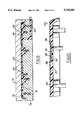
- FIG. 9 is a sectional view showing the injection mold of FIG. 8 after the mold parts have been closed and a hot melt material has been introduced into the mold.
- FIG. 10 is a sectional view of the composite article consisting of the icon embedded in the shell and the shell applied to a surface of the supporting member formed in the mold.
- the composite article 20 of this invention comprises an elongated supporting member 22, and an elongated shell 24 covering the front surface of the supporting member.
- the supporting member 22 and the shell 24 together make up the trim strip of an automotive vehicle.
- An icon 26 is secured to the exposed front surface of the shell 24.
- FIG. 4 shows the shell 24 and FIGS. 1-3 show a vacuum mold 28 for forming a plurality of shells from a sheet 30 of thermoplastic material.
- the shells 24 are simultaneously formed from the sheet 30 in the vacuum mold and then individually cut from the sheet.
- the thermoplastic sheet 30 may, for example, be made of acrylonitrile-butadiene-styrene (ABS).
- the vacuum mold 28 comprises a lower mold part 32 and an upper mold part 34.
- the lower mold part 32 is in the form of a rectangular box-shaped housing 36 having a vacuum chamber 38 therein.
- the top wall 40 of the housing 36 has a plurality of elongated, laterally spaced apart, raised mold forms 42 of like configuration to form and shape a plurality of shells.
- Vacuum passages 44 in the top wall 40 extend from the vacuum chamber through the mold forms 40.
- a vacuum line 46 leads to the chamber 38.
- the upper mold part 34 is in the form of a rectangular box-shaped housing 50 of about the same size as the lower mold part 34 and contains an elongated heating element 51.
- the sheet which may be preheated if desired, is laid over the mold forms 42 on the top wall 40 of the lower mold part, as shown in FIGS. 1 and 2.
- the upper mold part is brought down on the lower mold part to close the vacuum mold, and the heating element 51 is energized to a temperature sufficient to soften the sheet 30.
- Vacuum applied to chamber 38 draws the sheet down tightly on the mold forms 42 as in FIG. 2.
- the mold is opened and the sheet is allowed to cool after which it is removed.
- the finished sheet is shown in FIG. 3 and retains the configuration imparted to it in the vacuum mold.
- the individual shells 24 may be cut or trimmed from the sheet and appear as shown in FIG. 4.
- the shells are preferably on the order of about 0.020" thick.
- the icon 26 is shown in FIGS. 5 and 6.
- the icon may be any image, symbol, design or words or a combination thereof or any other representation that may be desired.
- the icon is the design of an eagle.
- the icon may be made of metal and may, for example, be chrome-plated nickel or gold-plated nickel, as desired.
- the icon is very thin.
- the icon may initially have its front side adhered to a transfer strip 52.
- the transfer strip 52 may be a transparent plastic such, for example, as Mylar which is a brand name for a polyester.
- a plurality of spaced-apart globs 60 of an adhesive is applied to the exposed back of the icon 26.
- the globs 60 are preferably formed of a heat-curable adhesive of a type which is at least tacky at room temperature and cures at the higher temperature of a subsequent injection molding operation to be described hereinafter.
- the adhesive may be a polyamide or a polyester.
- the icon 26 is applied to the front surface of the shell 24 by pressing its adhesive coated back against the shell and peeling away the Mylar carrier strip.
- FIG. 7 shows the icon applied to the shell after the Mylar carrier strip has been peeled away.
- the injection mold 70 is composed of two parts 72 and 74.
- the shell with the icon adhered to it is placed in the upper mold part as shown in FIG. 8 with its front surface, and the front surface of the icon, facing a mold surface 76.
- This mold surface 76 is configured to match the configuration of the shell.
- the injection mold is closed by bringing the mold parts 72 and 74 together as shown in FIG. 8 defining a mold cavity beneath the shell in which the supporting member 22 of the composite article is formed and molded.
- a thermoplastic hot melt material such as ABS
- the hot melt material is heated to be flowable and fills the mold to form the sturdy supporting member 22.
- the hot melt material is introduced under enough pressure to force the shell 24 into full surface-to-surface contact with the mold surface 76 of the mold part 72.
- the hot melt material and shell are compatible and bond to one another on the rear surface of the shell.
- the heat of the hot melt material is sufficient to soften the shell 24 and cause the icon 26 to form a recess 82 in the shell and the icon to become embedded in the recess.
- the heat of the hot melt material is sufficient to cure the adhesive 60 to form a strong bond between the back of the icon and the bottom of the recess. This bond is increased by the ridges 54 and grooves in the back of the icon.
- the heat of the molding operating will vary depending upon the hot melt material used but may be about 400° F. This degree of heat is enough to soften the shell and cause the icon to become fully embedded in the shell with the front surface of the icon substantially flush with the front surface of the shell.
- the mold is opened and the composite article consisting of the supporting member 22, shell 24 and icon 26, is removed.
- the icon in the finished composite article is protected on all sides around its periphery by reason of the fact that it is fully embedded in the shell with its front surface flush with the front surface of the shell.
- the edges 86 of the icon abut the edges of the recess and are protected and will not be chipped or damaged and the icon will not be inadvertently peeled away.
Landscapes
- Engineering & Computer Science (AREA)
- Mechanical Engineering (AREA)
- Manufacturing & Machinery (AREA)
- Chemical & Material Sciences (AREA)
- Composite Materials (AREA)
- Injection Moulding Of Plastics Or The Like (AREA)
Abstract
Description
Claims (4)
Priority Applications (1)
| Application Number | Priority Date | Filing Date | Title |
|---|---|---|---|
| US08/739,479 US5728443A (en) | 1995-10-11 | 1996-10-28 | Composite article of an automotive vehicle and method of making the same |
Applications Claiming Priority (2)
| Application Number | Priority Date | Filing Date | Title |
|---|---|---|---|
| US08/540,697 US5626704A (en) | 1995-10-11 | 1995-10-11 | Composite article of an automotive vehicle and method of making the same |
| US08/739,479 US5728443A (en) | 1995-10-11 | 1996-10-28 | Composite article of an automotive vehicle and method of making the same |
Related Parent Applications (1)
| Application Number | Title | Priority Date | Filing Date |
|---|---|---|---|
| US08/540,697 Division US5626704A (en) | 1995-10-11 | 1995-10-11 | Composite article of an automotive vehicle and method of making the same |
Publications (1)
| Publication Number | Publication Date |
|---|---|
| US5728443A true US5728443A (en) | 1998-03-17 |
Family
ID=24156568
Family Applications (2)
| Application Number | Title | Priority Date | Filing Date |
|---|---|---|---|
| US08/540,697 Expired - Lifetime US5626704A (en) | 1995-10-11 | 1995-10-11 | Composite article of an automotive vehicle and method of making the same |
| US08/739,479 Expired - Lifetime US5728443A (en) | 1995-10-11 | 1996-10-28 | Composite article of an automotive vehicle and method of making the same |
Family Applications Before (1)
| Application Number | Title | Priority Date | Filing Date |
|---|---|---|---|
| US08/540,697 Expired - Lifetime US5626704A (en) | 1995-10-11 | 1995-10-11 | Composite article of an automotive vehicle and method of making the same |
Country Status (1)
| Country | Link |
|---|---|
| US (2) | US5626704A (en) |
Cited By (4)
| Publication number | Priority date | Publication date | Assignee | Title |
|---|---|---|---|---|
| US6454974B1 (en) | 1998-12-21 | 2002-09-24 | Magna International Of America, Inc. | Method for vacuum pressure forming reinforced plastic articles |
| US20050048276A1 (en) * | 2001-06-21 | 2005-03-03 | Magna International Of America, Inc. | Structural foam composite having nano-particle reinforcement and method of making the same |
| US6977115B1 (en) | 1998-12-21 | 2005-12-20 | Magna International Of America, Inc. | Low pressure compression molded parts having nano-particle reinforced protrusions and method of making the same |
| US6988305B1 (en) | 1999-12-17 | 2006-01-24 | Magna International Of America, Inc. | Method and apparatus for blow molding large reinforced plastic parts |
Families Citing this family (12)
| Publication number | Priority date | Publication date | Assignee | Title |
|---|---|---|---|---|
| US20050225006A1 (en) * | 1995-11-01 | 2005-10-13 | Patent Holding Company | Method for molding metal-covered component |
| US6428738B1 (en) * | 1995-11-01 | 2002-08-06 | Patent Holding Company | Method of manufacturing an in-mold laminate component |
| US5874033A (en) * | 1997-02-05 | 1999-02-23 | Owens Corning Fiberglas Technology, Inc. | Process for preparing a laminar structure |
| US6620371B1 (en) * | 1998-05-22 | 2003-09-16 | Patent Holding Company | Method of manufacturing an in-mold laminate component |
| US6082762A (en) | 1998-05-22 | 2000-07-04 | Larry J. Winget | Air bag cover having a decorative applique preform bonded thereto and method of making same |
| US6818305B2 (en) | 1998-05-22 | 2004-11-16 | Patent Holding Company | Molding method and metal-covered component formed thereby |
| US7458631B2 (en) | 2004-10-19 | 2008-12-02 | International Automotive Components Group North America, Inc. | Automotive armrest with soft feel and method of making the same |
| US7156437B2 (en) * | 2004-10-19 | 2007-01-02 | Lear Corporation | Automotive trim part with applique and method of making same |
| US7478854B2 (en) * | 2004-10-19 | 2009-01-20 | International Automotive Components Group North America, Inc. | Automotive handle with soft feel and method of making the same |
| US20060099395A1 (en) * | 2004-11-09 | 2006-05-11 | Cowelchuk Glenn A | Automotive interior trim assembly and method |
| FR2907728B1 (en) * | 2006-10-25 | 2009-01-23 | Plastic Omnium Cie | LOT OF AT LEAST TWO DECORATIVE AND / OR PROTECTIVE ELEMENTS OF A BODY PANEL |
| US10464244B2 (en) * | 2017-02-15 | 2019-11-05 | Fca Us Llc | Injection mold for ultra thin wall components |
Citations (3)
| Publication number | Priority date | Publication date | Assignee | Title |
|---|---|---|---|---|
| US3687794A (en) * | 1971-03-09 | 1972-08-29 | Glass Lab Co | Combination decorative and safety composite molding |
| US3881042A (en) * | 1973-10-03 | 1975-04-29 | Standard Products Co | Adhesive barrier for plastic trim strip |
| US4446179A (en) * | 1982-05-21 | 1984-05-01 | The D. L. Auld Company | Trim strip for automobile bodies |
Family Cites Families (4)
| Publication number | Priority date | Publication date | Assignee | Title |
|---|---|---|---|---|
| US3108850A (en) * | 1960-11-23 | 1963-10-29 | American Can Co | Labeling of blown plastic containers |
| US3654062A (en) * | 1970-09-28 | 1972-04-04 | Standard Products Co | Injection molded decorative plaques |
| US4323411A (en) * | 1976-09-27 | 1982-04-06 | Owens-Illinois, Inc. | Method for applying prefabricated parts to blow molded articles |
| US5342666A (en) * | 1986-10-28 | 1994-08-30 | Rexham Industries Corp. | Injection molded plastic article with integral weatherable pigmented film surface |
-
1995
- 1995-10-11 US US08/540,697 patent/US5626704A/en not_active Expired - Lifetime
-
1996
- 1996-10-28 US US08/739,479 patent/US5728443A/en not_active Expired - Lifetime
Patent Citations (3)
| Publication number | Priority date | Publication date | Assignee | Title |
|---|---|---|---|---|
| US3687794A (en) * | 1971-03-09 | 1972-08-29 | Glass Lab Co | Combination decorative and safety composite molding |
| US3881042A (en) * | 1973-10-03 | 1975-04-29 | Standard Products Co | Adhesive barrier for plastic trim strip |
| US4446179A (en) * | 1982-05-21 | 1984-05-01 | The D. L. Auld Company | Trim strip for automobile bodies |
Cited By (7)
| Publication number | Priority date | Publication date | Assignee | Title |
|---|---|---|---|---|
| US6454974B1 (en) | 1998-12-21 | 2002-09-24 | Magna International Of America, Inc. | Method for vacuum pressure forming reinforced plastic articles |
| US20020190440A1 (en) * | 1998-12-21 | 2002-12-19 | Magna International Of America, Inc. | Method for vacuum pressure forming reinforced plastic articles |
| US6872432B2 (en) | 1998-12-21 | 2005-03-29 | Magna International Of America, Inc. | Hard top produced by method for vacuum pressure forming reinforced plastic articles |
| US6977115B1 (en) | 1998-12-21 | 2005-12-20 | Magna International Of America, Inc. | Low pressure compression molded parts having nano-particle reinforced protrusions and method of making the same |
| US6988305B1 (en) | 1999-12-17 | 2006-01-24 | Magna International Of America, Inc. | Method and apparatus for blow molding large reinforced plastic parts |
| US20050048276A1 (en) * | 2001-06-21 | 2005-03-03 | Magna International Of America, Inc. | Structural foam composite having nano-particle reinforcement and method of making the same |
| US7169467B2 (en) | 2001-06-21 | 2007-01-30 | Magna International Of America, Inc. | Structural foam composite having nano-particle reinforcement and method of making the same |
Also Published As
| Publication number | Publication date |
|---|---|
| US5626704A (en) | 1997-05-06 |
Similar Documents
| Publication | Publication Date | Title |
|---|---|---|
| US5728443A (en) | Composite article of an automotive vehicle and method of making the same | |
| US5672397A (en) | Composite article of an automotive vehicle | |
| CA2289728C (en) | Method for making smart cards | |
| US5604006A (en) | Label inmolding process and article of manufacture produced therefrom | |
| US5429786A (en) | Method of manufacturing resin member | |
| EP0742102A3 (en) | Print head and method of making a print head by one-shot injection molding | |
| JP5220977B2 (en) | Co-molded flock transfer body and process for producing the same | |
| KR940009007B1 (en) | Coated synthetic articles and method of making the same | |
| EP1157800A1 (en) | Method for joining synthetic resin to metallic plate | |
| JPH0531808A (en) | Manufacture of plastic joint product | |
| JP4359374B2 (en) | Method for producing molded product with film, mold | |
| KR100717711B1 (en) | Manufacturing method of injection article having decoration film layer | |
| JP4676607B2 (en) | Injection molding simultaneous painting method | |
| JPH03230918A (en) | Manufacture of metallic foil-plastic composite injection molding and its product | |
| JPH0523933B2 (en) | ||
| JPH03128739A (en) | Bright emblem and manufacture thereof | |
| JPH0852760A (en) | Printed decorative laminate | |
| US20050127577A1 (en) | Injection molded article having integral thermoplastic skin and method for making same | |
| JP3198594B2 (en) | Manufacturing method of decorative parts | |
| JPS63135213A (en) | Manufacture of decorative molding | |
| JP3020437B2 (en) | Molding terminal processing method | |
| US20030162455A1 (en) | Woody decorative item and method of manufacturing same | |
| JPH0615795A (en) | Insert label and decoration method | |
| JPH06106555A (en) | Molding method of integrated molded product with skin | |
| JP2000158479A (en) | Manufacture of film-inserted molding |
Legal Events
| Date | Code | Title | Description |
|---|---|---|---|
| STCF | Information on status: patent grant |
Free format text: PATENTED CASE |
|
| FPAY | Fee payment |
Year of fee payment: 4 |
|
| FPAY | Fee payment |
Year of fee payment: 8 |
|
| AS | Assignment |
Owner name: DAIMLERCHRYSLER CORPORATION, MICHIGAN Free format text: CHANGE OF NAME;ASSIGNOR:DAIMLERCHRYSLER CORPORATION;REEL/FRAME:016800/0852 Effective date: 19981116 |
|
| AS | Assignment |
Owner name: WILMINGTON TRUST COMPANY, DELAWARE Free format text: GRANT OF SECURITY INTEREST IN PATENT RIGHTS - FIRST PRIORITY;ASSIGNOR:CHRYSLER LLC;REEL/FRAME:019773/0001 Effective date: 20070803 Owner name: WILMINGTON TRUST COMPANY,DELAWARE Free format text: GRANT OF SECURITY INTEREST IN PATENT RIGHTS - FIRST PRIORITY;ASSIGNOR:CHRYSLER LLC;REEL/FRAME:019773/0001 Effective date: 20070803 |
|
| AS | Assignment |
Owner name: WILMINGTON TRUST COMPANY, DELAWARE Free format text: GRANT OF SECURITY INTEREST IN PATENT RIGHTS - SECOND PRIORITY;ASSIGNOR:CHRYSLER LLC;REEL/FRAME:019767/0810 Effective date: 20070803 Owner name: WILMINGTON TRUST COMPANY,DELAWARE Free format text: GRANT OF SECURITY INTEREST IN PATENT RIGHTS - SECOND PRIORITY;ASSIGNOR:CHRYSLER LLC;REEL/FRAME:019767/0810 Effective date: 20070803 |
|
| AS | Assignment |
Owner name: DAIMLERCHRYSLER COMPANY LLC, MICHIGAN Free format text: CHANGE OF NAME;ASSIGNOR:DAIMLERCHRYSLER CORPORATION;REEL/FRAME:021779/0793 Effective date: 20070329 |
|
| AS | Assignment |
Owner name: CHRYSLER LLC, MICHIGAN Free format text: CHANGE OF NAME;ASSIGNOR:DAIMLERCHRYSLER COMPANY LLC;REEL/FRAME:021826/0001 Effective date: 20070727 |
|
| AS | Assignment |
Owner name: US DEPARTMENT OF THE TREASURY, DISTRICT OF COLUMBI Free format text: GRANT OF SECURITY INTEREST IN PATENT RIGHTS - THIR;ASSIGNOR:CHRYSLER LLC;REEL/FRAME:022259/0188 Effective date: 20090102 Owner name: US DEPARTMENT OF THE TREASURY,DISTRICT OF COLUMBIA Free format text: GRANT OF SECURITY INTEREST IN PATENT RIGHTS - THIR;ASSIGNOR:CHRYSLER LLC;REEL/FRAME:022259/0188 Effective date: 20090102 |
|
| AS | Assignment |
Owner name: CHRYSLER LLC, MICHIGAN Free format text: RELEASE BY SECURED PARTY;ASSIGNOR:US DEPARTMENT OF THE TREASURY;REEL/FRAME:022902/0164 Effective date: 20090608 Owner name: CHRYSLER LLC,MICHIGAN Free format text: RELEASE BY SECURED PARTY;ASSIGNOR:US DEPARTMENT OF THE TREASURY;REEL/FRAME:022902/0164 Effective date: 20090608 |
|
| AS | Assignment |
Owner name: CHRYSLER LLC, MICHIGAN Free format text: RELEASE OF SECURITY INTEREST IN PATENT RIGHTS - FIRST PRIORITY;ASSIGNOR:WILMINGTON TRUST COMPANY;REEL/FRAME:022910/0498 Effective date: 20090604 Owner name: CHRYSLER LLC, MICHIGAN Free format text: RELEASE OF SECURITY INTEREST IN PATENT RIGHTS - SECOND PRIORITY;ASSIGNOR:WILMINGTON TRUST COMPANY;REEL/FRAME:022910/0740 Effective date: 20090604 Owner name: NEW CARCO ACQUISITION LLC, MICHIGAN Free format text: ASSIGNMENT OF ASSIGNORS INTEREST;ASSIGNOR:CHRYSLER LLC;REEL/FRAME:022915/0001 Effective date: 20090610 Owner name: THE UNITED STATES DEPARTMENT OF THE TREASURY, DIST Free format text: SECURITY AGREEMENT;ASSIGNOR:NEW CARCO ACQUISITION LLC;REEL/FRAME:022915/0489 Effective date: 20090610 Owner name: CHRYSLER LLC,MICHIGAN Free format text: RELEASE OF SECURITY INTEREST IN PATENT RIGHTS - FIRST PRIORITY;ASSIGNOR:WILMINGTON TRUST COMPANY;REEL/FRAME:022910/0498 Effective date: 20090604 Owner name: CHRYSLER LLC,MICHIGAN Free format text: RELEASE OF SECURITY INTEREST IN PATENT RIGHTS - SECOND PRIORITY;ASSIGNOR:WILMINGTON TRUST COMPANY;REEL/FRAME:022910/0740 Effective date: 20090604 Owner name: NEW CARCO ACQUISITION LLC,MICHIGAN Free format text: ASSIGNMENT OF ASSIGNORS INTEREST;ASSIGNOR:CHRYSLER LLC;REEL/FRAME:022915/0001 Effective date: 20090610 Owner name: THE UNITED STATES DEPARTMENT OF THE TREASURY,DISTR Free format text: SECURITY AGREEMENT;ASSIGNOR:NEW CARCO ACQUISITION LLC;REEL/FRAME:022915/0489 Effective date: 20090610 |
|
| AS | Assignment |
Owner name: CHRYSLER GROUP LLC, MICHIGAN Free format text: CHANGE OF NAME;ASSIGNOR:NEW CARCO ACQUISITION LLC;REEL/FRAME:022919/0126 Effective date: 20090610 Owner name: CHRYSLER GROUP LLC,MICHIGAN Free format text: CHANGE OF NAME;ASSIGNOR:NEW CARCO ACQUISITION LLC;REEL/FRAME:022919/0126 Effective date: 20090610 |
|
| FPAY | Fee payment |
Year of fee payment: 12 |
|
| AS | Assignment |
Owner name: CHRYSLER GROUP GLOBAL ELECTRIC MOTORCARS LLC, NORT Free format text: RELEASE BY SECURED PARTY;ASSIGNOR:THE UNITED STATES DEPARTMENT OF THE TREASURY;REEL/FRAME:026343/0298 Effective date: 20110524 Owner name: CHRYSLER GROUP LLC, MICHIGAN Free format text: RELEASE BY SECURED PARTY;ASSIGNOR:THE UNITED STATES DEPARTMENT OF THE TREASURY;REEL/FRAME:026343/0298 Effective date: 20110524 |
|
| AS | Assignment |
Owner name: CITIBANK, N.A., NEW YORK Free format text: SECURITY AGREEMENT;ASSIGNOR:CHRYSLER GROUP LLC;REEL/FRAME:026404/0123 Effective date: 20110524 |
|
| AS | Assignment |
Owner name: CITIBANK, N.A., NEW YORK Free format text: SECURITY AGREEMENT;ASSIGNOR:CHRYSLER GROUP LLC;REEL/FRAME:026435/0652 Effective date: 20110524 |
|
| AS | Assignment |
Owner name: JPMORGAN CHASE BANK, N.A., ILLINOIS Free format text: SECURITY AGREEMENT;ASSIGNOR:CHRYSLER GROUP LLC;REEL/FRAME:032384/0640 Effective date: 20140207 |
|
| AS | Assignment |
Owner name: FCA US LLC, MICHIGAN Free format text: CHANGE OF NAME;ASSIGNOR:CHRYSLER GROUP LLC;REEL/FRAME:035553/0356 Effective date: 20141203 |
|
| AS | Assignment |
Owner name: FCA US LLC, FORMERLY KNOWN AS CHRYSLER GROUP LLC, Free format text: RELEASE OF SECURITY INTEREST RELEASING SECOND-LIEN SECURITY INTEREST PREVIOUSLY RECORDED AT REEL 026426 AND FRAME 0644, REEL 026435 AND FRAME 0652, AND REEL 032384 AND FRAME 0591;ASSIGNOR:CITIBANK, N.A.;REEL/FRAME:037784/0001 Effective date: 20151221 |
|
| AS | Assignment |
Owner name: FCA US LLC (FORMERLY KNOWN AS CHRYSLER GROUP LLC), Free format text: RELEASE BY SECURED PARTY;ASSIGNOR:CITIBANK, N.A.;REEL/FRAME:042885/0255 Effective date: 20170224 |
|
| AS | Assignment |
Owner name: FCA US LLC (FORMERLY KNOWN AS CHRYSLER GROUP LLC), Free format text: RELEASE BY SECURED PARTY;ASSIGNOR:JPMORGAN CHASE BANK, N.A.;REEL/FRAME:048177/0356 Effective date: 20181113 |