US5735505A - Cable pulley device and method - Google Patents
Cable pulley device and method Download PDFInfo
- Publication number
- US5735505A US5735505A US08/617,103 US61710396A US5735505A US 5735505 A US5735505 A US 5735505A US 61710396 A US61710396 A US 61710396A US 5735505 A US5735505 A US 5735505A
- Authority
- US
- United States
- Prior art keywords
- strap
- cable
- wheel
- pulley device
- pulley
- Prior art date
- Legal status (The legal status is an assumption and is not a legal conclusion. Google has not performed a legal analysis and makes no representation as to the accuracy of the status listed.)
- Expired - Lifetime
Links
Images


Classifications
-
- G—PHYSICS
- G02—OPTICS
- G02B—OPTICAL ELEMENTS, SYSTEMS OR APPARATUS
- G02B6/00—Light guides; Structural details of arrangements comprising light guides and other optical elements, e.g. couplings
- G02B6/46—Processes or apparatus adapted for installing or repairing optical fibres or optical cables
- G02B6/50—Underground or underwater installation; Installation through tubing, conduits or ducts
- G02B6/54—Underground or underwater installation; Installation through tubing, conduits or ducts using mechanical means, e.g. pulling or pushing devices
- G02B6/545—Pulling eyes
-
- H—ELECTRICITY
- H02—GENERATION; CONVERSION OR DISTRIBUTION OF ELECTRIC POWER
- H02G—INSTALLATION OF ELECTRIC CABLES OR LINES, OR OF COMBINED OPTICAL AND ELECTRIC CABLES OR LINES
- H02G1/00—Methods or apparatus specially adapted for installing, maintaining, repairing or dismantling electric cables or lines
- H02G1/02—Methods or apparatus specially adapted for installing, maintaining, repairing or dismantling electric cables or lines for overhead lines or cables
- H02G1/04—Methods or apparatus specially adapted for installing, maintaining, repairing or dismantling electric cables or lines for overhead lines or cables for mounting or stretching
Definitions
- the invention herein pertains to installing cable in office buildings and other structures and particularly pertains to installing sensitive data communications cables such as identified as Category 5 or fiber optic, utilizing a lightweight pulley device by one installer.
- installers During wiring of buildings, whether with data cables such as Category 5 or with optical fiber cable, installers usually work in pairs in order to direct the sensitive cables along or around joists, rafters, and other structural components.
- the use of "teams” of installers is expensive with one team member often being idle for extended periods during the installation process.
- installers must be extremely careful in turning corners and in pulling cables from one level to another so that the cables are not unduly stressed or deformed. Consequently, with conventional techniques employed in installing fiber optic or other sensitive data communications cables, problems have arisen requiring the cables to be removed and reinstalled at a later date at great time and expense.
- the present invention was conceived and one of its objectives is to provide a data communications cable pulley device and method which will facilitate cable installation during building construction and retrofitting procedures.
- the invention herein provides a pulley device and method whereby sensitive data communications cable can be installed in office buildings and the like by a lone installer easily and without damage to the cable.
- a lightweight pulley device is provided having a pulley wheel attached to a closable strap.
- the strap includes a plurality of latches that are positioned along the flexible strap whereby the strap can be adjustably fastened to a stringer or other rigid support to hold the pulley in a desired position.
- a pulley guide is affixed to the strap for latching purposes.
- the flexible strap includes a designated break area whereby excess force on the pulley device, such as by overstretching the communications cable, will cause the strap to break and prevent damage to the communications cable during installation.
- the flexible strap utilizes a conventional "tie-wrap" configuration.
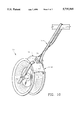
- FIG. 1 demonstrates the preferred form of the pulley device of the invention affixed to a building structural component.
- FIG. 2 depicts the pulley device as shown in FIG. 1 unattached and in an open posture
- FIG. 3 shows a right side view of the pulley device shown in FIG.
- FIG. 4 pictures the pulley device of FIGS. 1-3 with the strap in a linear posture
- FIG. 5 features another side view of the pulley device as shown unopened as in FIG. 2;
- FIG. 6 illustrates yet another embodiment of the pulley device
- FIG. 7 demonstrates a front view of the pulley device as shown in FIG. 6 with a pair of cables therein;
- FIG. 8 pictures a perspective view of another embodiment of the invention having a pulley fender
- FIG. 9 features the pulley device of FIG. 8 shown in exploded form
- FIG. 10 depicts a perspective view of still another embodiment of the invention.
- FIG. 11 shows the pulley fender as seen in FIG. 10 removed from the pulley device.
- FIG. 12 demonstrates a schematic view of a cable installation within an attic area of an office building.
- FIG. 1 illustrates the preferred form of cable pulley device 10 which is pivotally attached by conventional tie strap 11 to stringer 12 which may be, for example, a wooden 2" ⁇ 4" as conventionally used for construction purposes.
- stringer 12 which may be, for example, a wooden 2" ⁇ 4" as conventionally used for construction purposes.
- pulley device 10 may be formed entirely of a polymeric material such as nylon, polypropylene, or other suitable plastics.
- Pulley device 10 includes flexible strap 13 having a plurality of latches 14 therealong which are somewhat wedge-shaped and extend from the outer surface 15 of flexible strap 13. When used, pulley device 10 prevents a damaging acute angle being formed in cable 17 due to the relatively large diameter of pulley wheel 16 as compared to the diameter of cable 17.
- Typical data communications cable may be identified as Category 5 cable or optical fiber cable.
- First strap catch 18 is shown in FIG. 1 above pulley wheel 16 and a second strap catch 19 is affixed proximate the top of pulley wheel 16.
- cable pulley device 10 is shown in an open form prior to attachment to a stringer or other building component.
- pulley wheel 16 is attached to flexible strap 13 by axle 20 passing therethrough.
- pulley wheel 16 is rotatably positioned on axle 20 to allow cable 17 (FIG. 1) to move easily therealong.
- Cable guide 21 is mounted to inside surface 22 of flexible cable 13 with first strap catch 18 affixed thereto.
- Second strap catch 19 is joined to cable axle 20 through intermediate vertical strap catch support 23.
- Break area 25 is of lesser diameter and has been calculated, based on the tensile strength of strap 13, to break when a predetermined force is applied, and therefore release cable 17 before damage such as stretching of cable 17.
- FIG. 4 illustrates pulley device 10 with flexible strap 13 fully opened prior to placement around stringer 12 or the like as shown in FIG. 1.
- Wedge-shaped latches 14 as would be understood are flexible allowing easy placement through first strap catch 18 and second strap catch 19 as shown.
- FIG. 5 a front view of pulley device 10 is shown in open form as illustrated in FIG. 2.
- Pulley device 10 is preferably utilized by a lone installer, as no help is required to feed communications cables or lines around corners or turns. Instead, flexible strap 13 is attached as shown in FIG. 1 to provide universal pivoting action and with cable 17 positioned between cable guide 21 and wheel 16, cable 17 can then be pulled therealong through various turns and angles without fear of stretching, injuriously bending, or otherwise damaging cable 17.
- FIG. 6 another embodiment of the invention is illustrated whereby pulley device 30 is shown in a side elevational view.
- Flexible strap 31 is provided with teeth 32 along inside strap surface 33 as also shown in FIG. 7.
- Teeth 32 are of the conventional type as shown along tie strap 11 in FIG. 1 and do not protrude from strap 31 as do wedge-shaped latches 14 positioned on strap 13 as seen in FIGS. 1-5.
- first strap catch 34 is affixed to inside surface 33 of flexible strap 31 and as understood, first strap catch 34 maintains strap 31 in place as teeth 32 easily slide into and through first catch 34 and second catch 35, but strap 31 prohibits withdrawal.
- Second strap catch 35 is affixed to pulley wheel axle 36 and is so positioned to maintain strap 31 against the side surface of pulley wheel 38. With strap 31 so placed, each cable 37 is prevented from exiting the confinement provided by first strap catch 34, pulley wheel 38 and along the sides by flexible strap 31.
- pulley device 30 can be formed entirely of a conventional lightweight polymeric material whereby an installer can easily carry a number of pulley devices 30 without undue effort or inconvenience.
- pulley device 40 includes a flexible strap 41 affixed to pulley axle 42.
- Pulley fender 43 has sides 80, 80' which extend along the periphery of pulley wheel 48 and are contiguous thereto.
- Pulley fender 43 also has ends 81' which are perpendicular to the axis of rotation of pulley wheel 48 and are spaced from flexible strap 41 and each other. Ends 81, 81' span the entire width of pulley wheel 48.
- Pulley fender 43 has an arcuate cross-section and is slidably positioned on strap 41 and acts as a cable guide to prevent cable 50 (FIG. 12) from inadvertently slipping from pulley wheel 48.
- pulley device 40 is usually turned and twisted in a variety of positions as cable 50 is installed and fender 43 prevents cable 50 from inadvertently detaching from pulley device 40.
- Flexible strap 41 and fender 43 are molded from conventional plastics as is wheel 48.
- Pulley fender 43 includes a pair of strap brackets 44, 44' which include strap slots 45, 46, 45', 46' respectively. Bracket studs 47' (not shown) are attached to pulley fender 43 within brackets 44, 44' and help secure flexible strap 41 to pulley fender 43. As shown in FIG. 8, strap 41 includes a plurality of apertures 49, 49' for selectable attachment to respectively, bracket studs 47, 47'. Flexible strap 41 is joined to grooved pulley axle 42 by apertures 51, 51', seen also in FIG. 9. Thus, during cable installation, with flexible strap 41 positioned on a joist 60 as shown in FIG. 11, fender 43 will prevent cable 50 from escaping the confines of wheel
- FIG. 10 A further embodiment of the invention is shown in FIG. 10 wherein pulley device 70 is shown suspended by conventional tie strap 11.
- Pulley device 70 includes pulley fender 72 which also acts as a cable guide.
- fender 72 includes an arcuate cover 73 and a suspension strap protrubance 74.
- Protrubance 74 is open to allow conventional tie strap 11 to pass therethrough in an axial direction as shown along lines A--A or perpendicularly thereto along lines B--B for convenience in hanging as seen in FIG. 11.
- a pair of radial pulley straps 75, 75' are affixable to grooved axle 76 through apertures 77, 77'.
- FIG. 12 a typical pulley device installation is shown whereby metal roof joist 60 is used to hang pulley devices 40 by removing one or more ceiling tiles 65 as shown. Cable 50 can then be installed easily for data transmission or the like in the office building.
- FIGS. 1-10 are formed of a conventional polymeric material
- the pulley devices may be formed of metal or other materials suitable for plenum or non-plenum uses, as necessary.
- Other sizes and diameters of the pulley wheels may specific embodiments and examples shown herein are not intended to limit the scope as defined by the appended claims as other embodiments and equivalents are anticipated.
Abstract
Description
Claims (12)
Priority Applications (2)
| Application Number | Priority Date | Filing Date | Title |
|---|---|---|---|
| US08/617,103 US5735505A (en) | 1995-04-03 | 1996-03-18 | Cable pulley device and method |
| US09/005,678 US6045124A (en) | 1995-04-03 | 1998-01-12 | Cable pulley device |
Applications Claiming Priority (2)
| Application Number | Priority Date | Filing Date | Title |
|---|---|---|---|
| US08/415,856 US5618031A (en) | 1995-04-03 | 1995-04-03 | Cable pulley device and method |
| US08/617,103 US5735505A (en) | 1995-04-03 | 1996-03-18 | Cable pulley device and method |
Related Parent Applications (1)
| Application Number | Title | Priority Date | Filing Date |
|---|---|---|---|
| US08/415,856 Continuation-In-Part US5618031A (en) | 1995-04-03 | 1995-04-03 | Cable pulley device and method |
Related Child Applications (1)
| Application Number | Title | Priority Date | Filing Date |
|---|---|---|---|
| US09/005,678 Continuation US6045124A (en) | 1995-04-03 | 1998-01-12 | Cable pulley device |
Publications (1)
| Publication Number | Publication Date |
|---|---|
| US5735505A true US5735505A (en) | 1998-04-07 |
Family
ID=27023134
Family Applications (1)
| Application Number | Title | Priority Date | Filing Date |
|---|---|---|---|
| US08/617,103 Expired - Lifetime US5735505A (en) | 1995-04-03 | 1996-03-18 | Cable pulley device and method |
Country Status (1)
| Country | Link |
|---|---|
| US (1) | US5735505A (en) |
Cited By (13)
| Publication number | Priority date | Publication date | Assignee | Title |
|---|---|---|---|---|
| US5941507A (en) * | 1998-07-02 | 1999-08-24 | Page; Douglas Monroe | Cable installation guide |
| US6340271B1 (en) * | 1999-02-26 | 2002-01-22 | Wireline Technologies, Inc. | Conduit cable feeding sheave |
| US6375163B1 (en) * | 1999-02-26 | 2002-04-23 | Wireline Technologies, Inc. | Cable stringing block |
| US6814327B1 (en) * | 2002-04-18 | 2004-11-09 | Myer, Ii John D. | Support for holding and securing vacuum and pressure hoses associated with a carpet cleaning system |
| US20060064138A1 (en) * | 2004-04-30 | 2006-03-23 | Francisco Velasco | Method of treating mood disorders and/or anxiety disorders by brain stimulation |
| US20060141622A1 (en) * | 2004-11-17 | 2006-06-29 | Johe Karl K | Transplantation of human neural cells for treatment of neurodegenerative conditions |
| US20060212090A1 (en) * | 2005-03-01 | 2006-09-21 | Functional Neuroscience Inc. | Method of treating cognitive disorders using neuromodulation |
| US20060212091A1 (en) * | 2005-03-01 | 2006-09-21 | Functional Neuroscience Inc. | Method of treating depression, mood disorders and anxiety disorders using neuromodulation |
| US20070005115A1 (en) * | 2003-06-19 | 2007-01-04 | Lozano Andres M | Method of treating depression, mood disorders and anxiety disorders using neuromodulation |
| US9127788B2 (en) | 2012-11-16 | 2015-09-08 | Jameson Llc | Aerial sheave device |
| CN106848958A (en) * | 2017-04-13 | 2017-06-13 | 许陈菲 | A kind of cable orifice protecting device |
| US20180062361A1 (en) * | 2016-08-30 | 2018-03-01 | Maclean Power, L.L.C. | Double v stringing block |
| CN113422322A (en) * | 2021-07-21 | 2021-09-21 | 北京国电天昱建设工程有限公司 | Stringing pulley and stringing method for overhead line |
Citations (3)
| Publication number | Priority date | Publication date | Assignee | Title |
|---|---|---|---|---|
| US516268A (en) * | 1894-03-13 | Snatch-block | ||
| US2181072A (en) * | 1939-05-03 | 1939-11-21 | Sayers Eugene Thomas | Cable clamp |
| US2858106A (en) * | 1954-09-20 | 1958-10-28 | William G Anton | Guide for flexible lines |
-
1996
- 1996-03-18 US US08/617,103 patent/US5735505A/en not_active Expired - Lifetime
Patent Citations (3)
| Publication number | Priority date | Publication date | Assignee | Title |
|---|---|---|---|---|
| US516268A (en) * | 1894-03-13 | Snatch-block | ||
| US2181072A (en) * | 1939-05-03 | 1939-11-21 | Sayers Eugene Thomas | Cable clamp |
| US2858106A (en) * | 1954-09-20 | 1958-10-28 | William G Anton | Guide for flexible lines |
Cited By (21)
| Publication number | Priority date | Publication date | Assignee | Title |
|---|---|---|---|---|
| US5941507A (en) * | 1998-07-02 | 1999-08-24 | Page; Douglas Monroe | Cable installation guide |
| US6340271B1 (en) * | 1999-02-26 | 2002-01-22 | Wireline Technologies, Inc. | Conduit cable feeding sheave |
| US6375163B1 (en) * | 1999-02-26 | 2002-04-23 | Wireline Technologies, Inc. | Cable stringing block |
| US6814327B1 (en) * | 2002-04-18 | 2004-11-09 | Myer, Ii John D. | Support for holding and securing vacuum and pressure hoses associated with a carpet cleaning system |
| US8467878B2 (en) | 2003-06-19 | 2013-06-18 | Advanced Neuromodulation Systems, Inc. | Method of treating depression, mood disorders and anxiety disorders using neuromodulation |
| US7653433B2 (en) | 2003-06-19 | 2010-01-26 | Advanced Neuromodulation Systems, Inc. | Method of treating depression, mood disorders and anxiety disorders using neuromodulation |
| US8190264B2 (en) | 2003-06-19 | 2012-05-29 | Advanced Neuromodulation Systems, Inc. | Method of treating depression, mood disorders and anxiety disorders using neuromodulation |
| EP2277588A2 (en) | 2003-06-19 | 2011-01-26 | Advanced Neuromodulation Systems, Inc. | Method of treating depression, mood disorders and anxiety disorders using neuromodulation |
| US20070005115A1 (en) * | 2003-06-19 | 2007-01-04 | Lozano Andres M | Method of treating depression, mood disorders and anxiety disorders using neuromodulation |
| US20100114193A1 (en) * | 2003-06-19 | 2010-05-06 | Advanced Neuromodulation Systems, Inc. | Method of treating depression, mood disorders and anxiety disorders using neuromodulation |
| US7346395B2 (en) | 2003-06-19 | 2008-03-18 | Advanced Neuromodulation Systems, Inc. | Method of treating depression, mood disorders and anxiety disorders using neuromodulation |
| US7313442B2 (en) | 2004-04-30 | 2007-12-25 | Advanced Neuromodulation Systems, Inc. | Method of treating mood disorders and/or anxiety disorders by brain stimulation |
| US20060064138A1 (en) * | 2004-04-30 | 2006-03-23 | Francisco Velasco | Method of treating mood disorders and/or anxiety disorders by brain stimulation |
| US20060141622A1 (en) * | 2004-11-17 | 2006-06-29 | Johe Karl K | Transplantation of human neural cells for treatment of neurodegenerative conditions |
| US20060212091A1 (en) * | 2005-03-01 | 2006-09-21 | Functional Neuroscience Inc. | Method of treating depression, mood disorders and anxiety disorders using neuromodulation |
| US20060212090A1 (en) * | 2005-03-01 | 2006-09-21 | Functional Neuroscience Inc. | Method of treating cognitive disorders using neuromodulation |
| US9931500B2 (en) | 2005-03-01 | 2018-04-03 | Andres M. Lozano | Method of treating depression, mood disorders and anxiety disorders using neuromodulation |
| US9127788B2 (en) | 2012-11-16 | 2015-09-08 | Jameson Llc | Aerial sheave device |
| US20180062361A1 (en) * | 2016-08-30 | 2018-03-01 | Maclean Power, L.L.C. | Double v stringing block |
| CN106848958A (en) * | 2017-04-13 | 2017-06-13 | 许陈菲 | A kind of cable orifice protecting device |
| CN113422322A (en) * | 2021-07-21 | 2021-09-21 | 北京国电天昱建设工程有限公司 | Stringing pulley and stringing method for overhead line |
Similar Documents
| Publication | Publication Date | Title |
|---|---|---|
| US5735505A (en) | Cable pulley device and method | |
| US5740994A (en) | Cable support and method | |
| US5443232A (en) | Apparatus for hanging TV cable and the like | |
| US6565048B1 (en) | Cable support bracket assembly | |
| US5918837A (en) | Cable retainer bracket and method of installation | |
| US10361544B2 (en) | Cable and/or socket holder | |
| US7740211B2 (en) | Conduit attachment apparatus | |
| US5941507A (en) | Cable installation guide | |
| US6313406B1 (en) | Cable support | |
| US6045124A (en) | Cable pulley device | |
| US6222128B1 (en) | Cable support | |
| US5964434A (en) | Cable support and method | |
| US20100133389A1 (en) | Device for supporting a safety line | |
| US6325338B1 (en) | Bridle ring saddle | |
| US5618031A (en) | Cable pulley device and method | |
| EP2514054B1 (en) | Cable positioning arrangement | |
| US20020117574A1 (en) | Wire spool stay | |
| EP0390834B1 (en) | Quick-acting clamp, whose clamping force is a direct function of the load, for wires suspending weights, especially chandeliers | |
| CN114671307A (en) | Optical fiber jumper wire storage rack | |
| JPS587794Y2 (en) | Cable horizontal overhead line support structure | |
| JP2755474B2 (en) | Twisting method of self-supporting cable | |
| JPS5952241B2 (en) | How to install a suspension structure cable | |
| JPH0227642B2 (en) | ||
| JPS5932176Y2 (en) | High-rise cable pulling aid | |
| JP3404339B2 (en) | Leader for cable drawstring |
Legal Events
| Date | Code | Title | Description |
|---|---|---|---|
| AS | Assignment |
Owner name: DATA CONNECTIONS, INC., NORTH CAROLINA Free format text: ASSIGNMENT OF ASSIGNORS INTEREST;ASSIGNOR:WALTON, NEWTON C.;REEL/FRAME:007928/0392 Effective date: 19960308 |
|
| STCF | Information on status: patent grant |
Free format text: PATENTED CASE |
|
| FPAY | Fee payment |
Year of fee payment: 4 |
|
| FPAY | Fee payment |
Year of fee payment: 8 |
|
| AS | Assignment |
Owner name: GIBBS, R. RODOLPH, NORTH CAROLINA Free format text: ASSIGNMENT OF ASSIGNORS INTEREST;ASSIGNOR:DATA CONNECTIONS, INC.;REEL/FRAME:019094/0750 Effective date: 20070302 |
|
| AS | Assignment |
Owner name: NEWCOM, INC., NORTH CAROLINA Free format text: ASSIGNMENT OF ASSIGNORS INTEREST;ASSIGNOR:GIBBS, R. RODOLPH;REEL/FRAME:019331/0142 Effective date: 20070515 |
|
| AS | Assignment |
Owner name: CAPITALSOURCE FINANCE, LLC, A DELAWARE LIMITED LIA Free format text: FIRST AMENDMENT TO INTELLECTUAL PROPERTY SECURITY AGREEMENT;ASSIGNOR:JAMESON, LLC (F/K/A MACLEAN JAMESON, L.L.C.), A DELAWARE LIMITED LIABILITY COMPANY;REEL/FRAME:020353/0471 Effective date: 20071228 |
|
| AS | Assignment |
Owner name: JAMESON, LLC, SOUTH CAROLINA Free format text: ASSIGNMENT OF ASSIGNORS INTEREST;ASSIGNOR:NEWCOM, INC.;REEL/FRAME:020371/0160 Effective date: 20071228 |
|
| FEPP | Fee payment procedure |
Free format text: PAYOR NUMBER ASSIGNED (ORIGINAL EVENT CODE: ASPN); ENTITY STATUS OF PATENT OWNER: SMALL ENTITY |
|
| FPAY | Fee payment |
Year of fee payment: 12 |
|
| AS | Assignment |
Owner name: CAPITALSOURCE FINANCE, LLC, MARYLAND Free format text: RELEASE BY SECURED PARTY;ASSIGNOR:JAMESON, LLC;REEL/FRAME:037313/0332 Effective date: 20151217 |