US5737500A - Mobile dexterous siren degree of freedom robot arm with real-time control system - Google Patents
Mobile dexterous siren degree of freedom robot arm with real-time control system Download PDFInfo
- Publication number
- US5737500A US5737500A US08/431,361 US43136195A US5737500A US 5737500 A US5737500 A US 5737500A US 43136195 A US43136195 A US 43136195A US 5737500 A US5737500 A US 5737500A
- Authority
- US
- United States
- Prior art keywords
- joint
- arm
- joints
- defining
- robot arm
- Prior art date
- Legal status (The legal status is an assumption and is not a legal conclusion. Google has not performed a legal analysis and makes no representation as to the accuracy of the status listed.)
- Expired - Fee Related
Links
Images


Classifications
-
- B—PERFORMING OPERATIONS; TRANSPORTING
- B25—HAND TOOLS; PORTABLE POWER-DRIVEN TOOLS; MANIPULATORS
- B25J—MANIPULATORS; CHAMBERS PROVIDED WITH MANIPULATION DEVICES
- B25J9/00—Programme-controlled manipulators
- B25J9/16—Programme controls
- B25J9/1628—Programme controls characterised by the control loop
- B25J9/1643—Programme controls characterised by the control loop redundant control
-
- G—PHYSICS
- G05—CONTROLLING; REGULATING
- G05B—CONTROL OR REGULATING SYSTEMS IN GENERAL; FUNCTIONAL ELEMENTS OF SUCH SYSTEMS; MONITORING OR TESTING ARRANGEMENTS FOR SUCH SYSTEMS OR ELEMENTS
- G05B2219/00—Program-control systems
- G05B2219/30—Nc systems
- G05B2219/33—Director till display
- G05B2219/33169—Name of bus, vme-bus
-
- G—PHYSICS
- G05—CONTROLLING; REGULATING
- G05B—CONTROL OR REGULATING SYSTEMS IN GENERAL; FUNCTIONAL ELEMENTS OF SUCH SYSTEMS; MONITORING OR TESTING ARRANGEMENTS FOR SUCH SYSTEMS OR ELEMENTS
- G05B2219/00—Program-control systems
- G05B2219/30—Nc systems
- G05B2219/34—Director, elements to supervisory
- G05B2219/34403—RTI real time, kernel, processing
-
- G—PHYSICS
- G05—CONTROLLING; REGULATING
- G05B—CONTROL OR REGULATING SYSTEMS IN GENERAL; FUNCTIONAL ELEMENTS OF SUCH SYSTEMS; MONITORING OR TESTING ARRANGEMENTS FOR SUCH SYSTEMS OR ELEMENTS
- G05B2219/00—Program-control systems
- G05B2219/30—Nc systems
- G05B2219/39—Robotics, robotics to robotics hand
- G05B2219/39062—Calculate, jacobian matrix estimator
-
- G—PHYSICS
- G05—CONTROLLING; REGULATING
- G05B—CONTROL OR REGULATING SYSTEMS IN GENERAL; FUNCTIONAL ELEMENTS OF SUCH SYSTEMS; MONITORING OR TESTING ARRANGEMENTS FOR SUCH SYSTEMS OR ELEMENTS
- G05B2219/00—Program-control systems
- G05B2219/30—Nc systems
- G05B2219/39—Robotics, robotics to robotics hand
- G05B2219/39081—Inexact solution for orientation or other DOF with relation to type of task
-
- G—PHYSICS
- G05—CONTROLLING; REGULATING
- G05B—CONTROL OR REGULATING SYSTEMS IN GENERAL; FUNCTIONAL ELEMENTS OF SUCH SYSTEMS; MONITORING OR TESTING ARRANGEMENTS FOR SUCH SYSTEMS OR ELEMENTS
- G05B2219/00—Program-control systems
- G05B2219/30—Nc systems
- G05B2219/39—Robotics, robotics to robotics hand
- G05B2219/39082—Collision, real time collision avoidance
-
- G—PHYSICS
- G05—CONTROLLING; REGULATING
- G05B—CONTROL OR REGULATING SYSTEMS IN GENERAL; FUNCTIONAL ELEMENTS OF SUCH SYSTEMS; MONITORING OR TESTING ARRANGEMENTS FOR SUCH SYSTEMS OR ELEMENTS
- G05B2219/00—Program-control systems
- G05B2219/30—Nc systems
- G05B2219/39—Robotics, robotics to robotics hand
- G05B2219/39172—Vehicle, coordination between manipulator arm and its moving vehicle
-
- G—PHYSICS
- G05—CONTROLLING; REGULATING
- G05B—CONTROL OR REGULATING SYSTEMS IN GENERAL; FUNCTIONAL ELEMENTS OF SUCH SYSTEMS; MONITORING OR TESTING ARRANGEMENTS FOR SUCH SYSTEMS OR ELEMENTS
- G05B2219/00—Program-control systems
- G05B2219/30—Nc systems
- G05B2219/39—Robotics, robotics to robotics hand
- G05B2219/39174—Add DOFs of mobility to DOFs of manipulator to add user defined tasks to motion
-
- G—PHYSICS
- G05—CONTROLLING; REGULATING
- G05B—CONTROL OR REGULATING SYSTEMS IN GENERAL; FUNCTIONAL ELEMENTS OF SUCH SYSTEMS; MONITORING OR TESTING ARRANGEMENTS FOR SUCH SYSTEMS OR ELEMENTS
- G05B2219/00—Program-control systems
- G05B2219/30—Nc systems
- G05B2219/39—Robotics, robotics to robotics hand
- G05B2219/39414—7-DOF
-
- G—PHYSICS
- G05—CONTROLLING; REGULATING
- G05B—CONTROL OR REGULATING SYSTEMS IN GENERAL; FUNCTIONAL ELEMENTS OF SUCH SYSTEMS; MONITORING OR TESTING ARRANGEMENTS FOR SUCH SYSTEMS OR ELEMENTS
- G05B2219/00—Program-control systems
- G05B2219/30—Nc systems
- G05B2219/39—Robotics, robotics to robotics hand
- G05B2219/39422—7-DOF for arm and 6-DOF for end effector
-
- G—PHYSICS
- G05—CONTROLLING; REGULATING
- G05B—CONTROL OR REGULATING SYSTEMS IN GENERAL; FUNCTIONAL ELEMENTS OF SUCH SYSTEMS; MONITORING OR TESTING ARRANGEMENTS FOR SUCH SYSTEMS OR ELEMENTS
- G05B2219/00—Program-control systems
- G05B2219/30—Nc systems
- G05B2219/40—Robotics, robotics mapping to robotics vision
- G05B2219/40252—Robot on track, rail moves only back and forth
-
- G—PHYSICS
- G05—CONTROLLING; REGULATING
- G05B—CONTROL OR REGULATING SYSTEMS IN GENERAL; FUNCTIONAL ELEMENTS OF SUCH SYSTEMS; MONITORING OR TESTING ARRANGEMENTS FOR SUCH SYSTEMS OR ELEMENTS
- G05B2219/00—Program-control systems
- G05B2219/30—Nc systems
- G05B2219/40—Robotics, robotics mapping to robotics vision
- G05B2219/40293—Gantry, portal
-
- G—PHYSICS
- G05—CONTROLLING; REGULATING
- G05B—CONTROL OR REGULATING SYSTEMS IN GENERAL; FUNCTIONAL ELEMENTS OF SUCH SYSTEMS; MONITORING OR TESTING ARRANGEMENTS FOR SUCH SYSTEMS OR ELEMENTS
- G05B2219/00—Program-control systems
- G05B2219/30—Nc systems
- G05B2219/40—Robotics, robotics mapping to robotics vision
- G05B2219/40297—Macro manipulator and microhand, distributed positioning
-
- G—PHYSICS
- G05—CONTROLLING; REGULATING
- G05B—CONTROL OR REGULATING SYSTEMS IN GENERAL; FUNCTIONAL ELEMENTS OF SUCH SYSTEMS; MONITORING OR TESTING ARRANGEMENTS FOR SUCH SYSTEMS OR ELEMENTS
- G05B2219/00—Program-control systems
- G05B2219/30—Nc systems
- G05B2219/40—Robotics, robotics mapping to robotics vision
- G05B2219/40298—Manipulator on vehicle, wheels, mobile
-
- G—PHYSICS
- G05—CONTROLLING; REGULATING
- G05B—CONTROL OR REGULATING SYSTEMS IN GENERAL; FUNCTIONAL ELEMENTS OF SUCH SYSTEMS; MONITORING OR TESTING ARRANGEMENTS FOR SUCH SYSTEMS OR ELEMENTS
- G05B2219/00—Program-control systems
- G05B2219/30—Nc systems
- G05B2219/40—Robotics, robotics mapping to robotics vision
- G05B2219/40317—For collision avoidance and detection
-
- G—PHYSICS
- G05—CONTROLLING; REGULATING
- G05B—CONTROL OR REGULATING SYSTEMS IN GENERAL; FUNCTIONAL ELEMENTS OF SUCH SYSTEMS; MONITORING OR TESTING ARRANGEMENTS FOR SUCH SYSTEMS OR ELEMENTS
- G05B2219/00—Program-control systems
- G05B2219/30—Nc systems
- G05B2219/40—Robotics, robotics mapping to robotics vision
- G05B2219/40327—Calculation, inverse kinematics solution using damped least squares method
-
- G—PHYSICS
- G05—CONTROLLING; REGULATING
- G05B—CONTROL OR REGULATING SYSTEMS IN GENERAL; FUNCTIONAL ELEMENTS OF SUCH SYSTEMS; MONITORING OR TESTING ARRANGEMENTS FOR SUCH SYSTEMS OR ELEMENTS
- G05B2219/00—Program-control systems
- G05B2219/30—Nc systems
- G05B2219/40—Robotics, robotics mapping to robotics vision
- G05B2219/40342—Minimize sum of gravitational torques of some joints
-
- G—PHYSICS
- G05—CONTROLLING; REGULATING
- G05B—CONTROL OR REGULATING SYSTEMS IN GENERAL; FUNCTIONAL ELEMENTS OF SUCH SYSTEMS; MONITORING OR TESTING ARRANGEMENTS FOR SUCH SYSTEMS OR ELEMENTS
- G05B2219/00—Program-control systems
- G05B2219/30—Nc systems
- G05B2219/40—Robotics, robotics mapping to robotics vision
- G05B2219/40345—Minor measure
-
- G—PHYSICS
- G05—CONTROLLING; REGULATING
- G05B—CONTROL OR REGULATING SYSTEMS IN GENERAL; FUNCTIONAL ELEMENTS OF SUCH SYSTEMS; MONITORING OR TESTING ARRANGEMENTS FOR SUCH SYSTEMS OR ELEMENTS
- G05B2219/00—Program-control systems
- G05B2219/30—Nc systems
- G05B2219/40—Robotics, robotics mapping to robotics vision
- G05B2219/40362—Elbow high or low, avoid obstacle collision with redundancy control
-
- G—PHYSICS
- G05—CONTROLLING; REGULATING
- G05B—CONTROL OR REGULATING SYSTEMS IN GENERAL; FUNCTIONAL ELEMENTS OF SUCH SYSTEMS; MONITORING OR TESTING ARRANGEMENTS FOR SUCH SYSTEMS OR ELEMENTS
- G05B2219/00—Program-control systems
- G05B2219/30—Nc systems
- G05B2219/40—Robotics, robotics mapping to robotics vision
- G05B2219/40371—Control trajectory to avoid joint limit as well as obstacle collision
-
- G—PHYSICS
- G05—CONTROLLING; REGULATING
- G05B—CONTROL OR REGULATING SYSTEMS IN GENERAL; FUNCTIONAL ELEMENTS OF SUCH SYSTEMS; MONITORING OR TESTING ARRANGEMENTS FOR SUCH SYSTEMS OR ELEMENTS
- G05B2219/00—Program-control systems
- G05B2219/30—Nc systems
- G05B2219/40—Robotics, robotics mapping to robotics vision
- G05B2219/40379—Manipulability
Definitions
- the invention is related to the use of the configuration control method disclosed in U.S. Pat. No. 4,999,553 by one of the inventors herein to the control of seven degree of freedom robot arms, using a kinematic approach.
- Redundant manipulators have an infinite number of joint motions which lead to the same end-effector trajectory. This richness in the choice of joint motions complicates the manipulator control problem considerably.
- the kinematic component of a redundant manipulator control scheme must generate a set of joint angle trajectories, from the infinite set of possible trajectories, which causes the end-effector to follow a desired trajectory while satisfying additional constraints, such as collision avoidance, servomotor torque minimization, singularity avoidance, or joint limit avoidance.
- additional constraints such as collision avoidance, servomotor torque minimization, singularity avoidance, or joint limit avoidance.
- redundancy resolution is an important evolutionary step toward versatile manipulation
- research activity in redundancy resolution and related areas has grown considerably in recent years, e.g. 3-10!.
- researchers have been working with a set of analytical tools based on linearized differential/kinematics models.
- Previous investigations of redundant manipulators have often focused on local/optimization for redundancy resolution by using the Jacobian pseudoinverse to solve the instantaneous relationship between the joint and end-effector velocities. Redundancy resolution based on the Jacobian pseudoinverse was first proposed by Whitney 3! in 1969, and the null-space projection improvement was proposed byoutheasternois 4! in 1977.
- the present invention also provides the remote inspection system with a mobile dexterous robotic manipulator for sensor placement including an associated multi-mode real-time control system.
- the mobility of the manipulator is accomplished by a motorized mobile platform.
- Section 2 describes the kinematics of the 7 DOF Robotics Research arm and gives an overview of the configuration control approach.
- Various applications of the configuration control approach to the 7 DOF arm providing elbow control, collision avoidance, and optimal joint movement are given in Section 3.
- Section 4 describes the laboratory setup and the implementation of configuration control for real-time motion control of the 7 DOF arm, with elbow positioning for redundancy resolution.
- Section 5 describes the configuration control approach for the manipulator with the motorized mobile platform.
- Section 6 describes the implementation of the configuration control for real-time motion control of the manipulator with the motorized mobile platform.
- Section 7 describes the graphics simulation of the manipulator with the motorized mobile platform.
- the Robotics Research (RR) arm is one of the few kinematically-redundant manipulators that is commercially available at the present time 12!.
- the Model K1207 RR arm has been purchased by JPL and similar models by other NASA centers for research and development of technologies applicable to the NASA Space Telerobotics Projects.
- the Robotics Research arm has an anthropomorphic design with seven revolute joints, as shown in FIG. 1 and has nonzero offsets at all the joints.
- the arm is composed of a number of "modules" with roll and pitch motions.
- the shoulder joint with roll and pitch motions moves the upper-arm;
- the elbow joint with roll and pitch actions drives the forearm; and
- the 7 DOF arm is obtained by adding the upper-arm roll as the 7th joint to a conventional 6 DOF arm design.
- the RR arm is supported by a pedestal at the base.
- the hand Jacobian matrix is computed using the vector cross-product form 14! ##EQU5## where z i is the unit vector along the z-axis of link frame ⁇ i ⁇ , and P i is the position vector from the origin O i of link frame ⁇ i ⁇ to the origin of hand frame ⁇ 7 ⁇ .
- the Jacobian matrix in (4) can be
- a seven-degree-of-freedom robot arm with a six-degree-of-freedom end effector is controlled by a processor employing a 6-by-7 Jacobian matrix for defining location and orientation of the end effector in terms of the rotation angles of the joints, a 1 (or more)-by-7 Jacobian matrix for defining 1 (or more) user-specified kinematic functions constraining location or movement of selected portions of the arm in terms of the joint angles, the processor combining the two Jacobian matrices to produce an augmented 7 (or more)-by-7 Jacobian matrix, the processor effecting control by computing in accordance with kinematics from the augmented 7-by-7 Jacobian matrix and from the seven joint angles of the arm a set of seven desired joint angles for transmittal to the joint servo loops of the arms.
- One of the kinematic functions constrains the orientation of the elbow plane of the arm. Another one of the kinematic functions minimizing a sum of gravitational torques on the joints. Still another one of the kinematic functions constrains the location of the arm to perform collision avoidance. Generically, one of the kinematic functions minimizes a sum of selected mechanical parameters of at least some of the joints associated with weighting coefficients which may be changed during arm movement. The mechanical parameters may be velocity errors or position errors or gravity torques associated with individual joints.
- the present invention also provides a mobile redundant dexterous manipulator including a real-time control system with multiple modes of operation.
- the manipulator is a seven degree-of-freedom arm mounted on a motorized platform.
- the manipulator-plus-platform system has two degrees-of-redundancy for the task of hand placement and orientation. The redundancy resolution is achieved by accomplishing two additional tasks using the configuration control technique.
- This mobile manipulator with control system allows a choice of arm angle control or collision avoidance for the seventh task, and platform placement or elbow angle control for the eighth task.
- joint limit avoidance task is automatically invoked when any of the joints approach their limits.
- This mobile manipulator with control system is robust to singularities, and also provides the capability of assigning weighting factors to end-effector and redundancy resolution tasks.
- the motion control algorithms controlling the mobile robot are executed at approximately 1.1 ms also on the VME-based chassis with two Motorola MC68040 processor boards.
- FIG. 1 is a perspective view of a seven degree of freedom robot arm of the type controlled in the present invention.
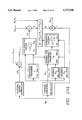
- FIG. 2 is a block diagram of an architecture embodying the present invention.
- FIG. 3 is a diagram of the robot arm of FIG. 1 in one position of interest.
- FIGS. 4a, 4b, 4c and 4d are diagrams of the robot arm of FIG. 1 in various positions of interest.
- FIG. 5 is a diagram illustrating the coordinates employed in the detailed description of the invention below.
- FIG. 6 is a graph illustrating the arm angle as a function of the number of sampling steps in one implementation of the invention.
- FIGS. 7a and 7b are graphs illustrating joint angles of respective joints of the arm of FIG. 1 as a function of the number of sampling steps in an implementation of the invention.
- FIGS. 8a and 8b are graphs illustrating a collision weighting factor and a collision avoidance critical distance, respectively, as a function of the number of sampling steps in an implementation of the invention.
- FIG. 9 is a graph illustrating the variation of the arm angle as a function of the number of sampling steps in an implementation of the invention.
- FIG. 10 is a graph illustrating various joint angles as a function of the number of sampling steps in an implementation of the invention.
- FIG. 11 is a block diagram of a hardware system employed in carrying out one embodiment of the present invention.
- FIGS. 12a through 12g are graphs illustrating errors in respective parameters of joint position and joint angle as a function of time in an implementation of the invention.
- FIG. 13a illustrates the architecture corresponding to Equations (8) and (10) as shown in FIG. 2 additionally including an additional Platform Motion Control routine for position control of the mobile platform.
- FIG. 13b illustrates a Cartesian control flow diagram for the manipulator.
- FIG. 14 illustrates the hardware of the 7 DOF Arm with 1 DOF mobile platform.
- FIG. 15 illustrates a two link approximation of the manipulator with the mobile platform.
- FIG. 16 illustrates the Platform Motion Control routine of FIG. 13a in detail.
- FIG. 17 shows a sample IRIS workstation graphical user interface with windows for manipulator control.
- FIG. 18 illustrates a sample software architecture of the system of the present invention operating in a VME environment.
- FIG. 19 illustrates the experimental results on the real-time control of the mobile manipulator system of the present invention.
- the configuration control approach introduced in 11! is a viable technique for resolution of redundancy and motion control of redundant manipulators.
- This is contrast to the conventional Jacobian pseudoinverse methods which resolve the redundancy at the velocity (i.e., differential kinematics) level.
- the configuration control approach can be implemented either as a dynamic or a kinematic control law.
- the configuration controller produces the appropriate joint torques ⁇ (t) using a joint-space or a task-space formulation.
- the controller In the kinematic control implementation 17!, the controller generates the appropriate joint angle trajectories ⁇ d (t) which are then used as setpoints for the low-level joint servo-loops.
- we adopt the kinematic configuration control approach due to ease of implementation. Since the Robotics Research arm has non-zero joint offsets, there are no closed-form analytical inverse kinematic solutions and therefore a differential kinematics approach must be adopted.
- ⁇ and X are the actual values while ⁇ d and X d are the desired values. Note that the use of X in (8) corrects for linearization errors due to differential kinematics.
- the configuration control framework allows the user to specify multiple additional tasks to be accomplished simultaneously with the basic task of hand motion.
- the augmented differential kinematics model becomes ##EQU12##
- E e Y d -J e ⁇ and E c ⁇ d -J c ⁇ are the basic task and additional task velocity errors.
- the task weighting factors W e , W c enable the user to assign priorities to the different basic and additional task requirements.
- the joint velocity weighting factor W v allows the user to suppress large joint velocities near singularities, at the expense of small task errors. This is particularly important in redundant arm control because the complicated nature of the augmented Jacobian singularities deters any analytical characterization of the singular configurations.
- Equation (8) and (10) An architecture corresponding to Equations (8) and (10) is illustrated in FIG. 2.
- Equation (10) can be written as ##EQU13## where J ci is the Jacobian related to ⁇ i . Equation (13) shows the contribution of each additional task constraint to the optimal joint motion.
- the configuration control formulation can be used to meet diverse additional task constraints for redundancy resolution 20!.
- the redundancy can be used to control directly: a geometrical variable (such as coordinates of a point on the arm), a physical variable (e.g. a joint gravity torque), or a mathematical function (such as projected gradient of an optimization function).
- a geometrical variable such as coordinates of a point on the arm
- a physical variable e.g. a joint gravity torque
- a mathematical function such as projected gradient of an optimization function
- the Silicon Graphics IRIS 4D70-GT is a Workstation with both high-speed computing and graphics capabilities, and is used in this simulation study.
- a three-dimensional color rendering of the Robotics Research K1207 arm is built with a set of primitives that use the IRIS "C" language graphics library.
- the rendering of the arm is centered on the screen with the joint angles, Cartesian hand coordinates, arm angle, manipulability indices, and trajectory time information displayed in a table in the lower left corner, the redundancy control mode is displayed in the upper left, and the user menu box (not shown) appears as needed in the upper right corner of the screen.
- FIGS. 4(a)-(d) show the evolution of the arm as it moves from an initial to a user-specified final configuration.
- the control law is computed and used to continuously change the arm configuration and the state information in the lower left corner of the screen is updated at every sampling instant.
- a simple cycloidal trajectory generator provides point-to-point straight-line Cartesian paths based on Cartesian goal points input by the user either from the keyboard or from the mouse.
- the user may use the mouse in teleoperation mode to directly control the arm in joint or Cartesian space, activating different degrees-of-freedom with the mouse buttons.
- the user may save a sequence of intermediate points to a file for a later run.
- the user can also select from a number of redundancy resolution schemes for each task, adjust optimization parameters or obstacle location, plot the results of each run, or save the data for later analysis.
- the user may also rerun the simulation program, adjusting his viewing location and perspective on each run.
- This interactive graphics simulation environment serves as an essential tool for development and validation of new control schemes for redundant 7 DOF arms.
- the IRIS also allows the user to simulate the robot workspace graphically and plan the task sequence. It can then be used for "task preview" by simulating the robot control algorithms and animating the task scenario. In this mode of operation, the IRIS can be used for operator training and rehearsal, prior to actual task execution. This preview mode is important in dealing with redundant arms, since it enables the user to explore various alternatives for redundancy resolution and can reveal unexpected behavior of the robot.
- elbow position is the "arm angle" ⁇ defined as the angle between the arm plane SEW and a reference plane, such as the vertical plane passing through the line SW, 15!, as depicted in FIG. 5.
- the angle ⁇ succinctly characterizes the self-motion of the arm and uniquely specifies the elbow position for a given hand frame.
- Other viable representations of the elbow position are the x, y, or z Cartesian coordinates of the elbow (i.e., E x , E y , or E z ) in the base frame.
- the choice of ⁇ or a particular elbow coordinate is clearly dictated by the task that the arm is required to perform.
- the user interacts with the IRIS Workstation by using the keyboard to enter the desired target position and orientation of the hand (x f ,y f , z f , ⁇ f , ⁇ f , ⁇ f ) and the desired final arm angle ⁇ f , as well as the duration of motion ⁇ and the sampling period ⁇ t.
- the hand frame can alternatively be input using the mouse which essentially emulates a 6 DOF cursor.
- the trajectory generator software then computes smooth cycloidal trajectories for these seven variables to change them from their initial values (x 0 , y 0 , z 0 , ⁇ 0 , ⁇ 0 , ⁇ 0 , ⁇ 0 , ⁇ 0 ) to the final values in the specified time duration. For instance, a typical cycloidal trajectory for the desired arm angle ⁇ d is ##EQU15##
- the hand is commanded to trace a triangle by making the successive moves: P 0 ⁇ .sup. ⁇ .sbsp.1 P 1 , P 1 ⁇ .sup. ⁇ .sbsp.2 P 2 , P 2 ⁇ .sup. ⁇ .sbsp.3 P 0 , where
- FIG. 6 shows the executed motion of the elbow, in which the arm angle changes from 0° to -90° and then to +45° during the hand motion.
- the variations of the joint angles ⁇ 1 , . . . , ⁇ 7 to achieve the commanded arm motion are shown in FIGS. 7a-7b.
- One of the advantages of the 7 DOF arm is the potential to use the "extra" DOF to maneuver in a congested workspace and avoid collision with obstacles by configuring the arm appropriately without perturbing the hand trajectory.
- all workspace obstacles are enclosed in convex volumes and each volume defines a "space of influence” (SOI) for the control law.
- SOI space of influence
- the SOIs are assumed to be spheres in the three-dimensional workspace, but extension to other geometrical shapes is possible using distance functions 21!.
- variable task weighting scheme alleviates both the chattering and discontinuity problems.
- the weighting factors w el and w co for the elbow control and collision avoidance tasks Cases One and Two are chosen as functions of the critical distance d c ( ⁇ ), instead of predefined constants.
- the use of variable weighting factors for the additional tasks allows the collision avoidance constraint to be incorporated gradually with the basic task, and furthermore circumvents the discontinuity problem in switching between different additional tasks.
- the obstacle is enclosed by two SOIs: an inner SOI which touches the actual obstacle boundary, and an outer SOI which allows for some "buffer.”
- FIGS. 8a-8b The variations of w co and the critical distance d c ( ⁇ ) are shown in FIGS. 8a-8b. It is seen that the increase in w co has hindered motion of the arm inside the inner SOI, thus ensuring that collision avoidance is successfully accomplished throughout the arm motion.
- the variation of the arm angle ⁇ ( ⁇ ) is shown in FIG. 9, and illustrates that the arm angle is held constant when the obstacle is not encountered, as expected.
- the redundancy resolution goal is to distribute the hand motion among the joints in such a way that a weighted sum of joint movements is kept at minimum.
- the optimization objective function is selected as ##EQU21## where k i is the weighting factor for joint i movement and ⁇ i (t)- ⁇ i (0)! 2 denotes the current deviation of joint angle ⁇ i (t) from its initial position ⁇ i (0).
- the objective function G( ⁇ ) (19) represents the total instantaneous potential energy stored in seven hypothetical springs attached to the robot joints with stiffness coefficients ⁇ k i ⁇ an natural lengths ⁇ i (0) ⁇ .
- the configuration control approach can then be applied to obtain the joint trajectories which cause the hand to attain the commanded motion with an optimal total joint spring energy.
- the program then computes ##EQU24## and augments the hand Jacobian J e to obtain J.
- the variations of the joint angles are given in FIG. 10, which shows that the first joint with a large weighting factor has moved considerably less than the other joints, as desired.
- redundancy resolution options are an area of current research, and analytical techniques that are being developed are added to the menu for test and validation. In this section, we shall present some of the items on the redundancy resolution menu.
- the resulting Jacobian J e is always singular, which implies that from a physical point of view, the hand position and orientation can not be changed arbitrarily while ⁇ j is locked.
- the joint locking option is useful in investigating the fail-tolerance feature of the robot joints, i.e., preservation of hand motion despite a joint failure.
- this option can be exercised when the operation only wishes to perform the basic task of hand placement and orientation.
- the Robotics Research Laboratory at JPL consists of one Model K1207 7 DOF arm and control unit from the Robotics Research Corporation, a VME-based chassis with MC 68020 processor boards, two 3 DOF industrial rate joysticks, a motorized lathe-bed, and a Silicon Graphics IRIS Workstation.
- the arm pedestal is mounted on a mobile platform of the lathe-bed which provides one additional degree-of-freedom.
- the joint servomotors can be commanded in any of the four modes: position, velocity, torque, and current. This makes it possible to operate the arm under either kinematic or dynamic control schemes, and therefore provides a testbed for validation of different 7 DOF control laws. In the present implementation, all seven joints are commanded in the position mode.
- the hardware diagram of the experimental setup is shown in FIG. 11.
- the IRIS can operate in two different modes. First, it creates an interactive graphics simulation environment for analysis and control of the 7 DOF arm, as discussed in Section 3. Second, the IRIS serves as the graphical user interface through which the operator interacts with the actual arm in real-time and issues motion commands in joint or task space. Using this dual-mode functionality, the IRIS can be used initially in "preview mode” for animating the task scenario, and subsequently in "execution mode” to command the arm to duplicate the simulated motion.
- the software which provides graphical user interface and simulation capabilities resides on the IRIS.
- the VME-based real-time robot control system receives commands from the IRIS to move the actual arm. This is the part of the system which handles all real-time operations including computation of control laws and transmission of appropriate signals to the multibus-based arm control unit.
- the control unit dispatches the commands for execution to the seven joint motors of the arm to perform the task.
- the VME chassis configuration contains five CPU boards that communicate through a shared memory board to perform all the necessary computations to provide real-time manipulator control.
- the first CPU interfaces with the high-level software residing on the IRIS, receives commands from the operator and obtains acknowledgment and state information from the low level after command execution.
- This processor also serves as the master by scheduling the synchronous operations of the slave processors that perform the real-time computations.
- the second CPU performs real-time trajectory generation and kinematic computations. This includes generating the desired end-effector trajectories and computing the necessary kinematic and Jacobian transformations.
- the second CPU also accesses and updates the world model and performs computations to resolve the manipulator redundancy.
- the third CPU is designated to perform all the computations associated with invoking various dynamic control algorithms (not used at present).
- the fourth CPU solely communicates with the arm control unit by executing the arm interface driver at every 2.5 milliseconds.
- a two-card VME-to-multibus adaptor set from the BIT3 Corporation is employed to provide shared memory servo interface with the arm control unit at high speed. The role of the driver is to perform handshake with the arm control unit and to convert data into appropriate format for usage.
- the fifth CPU hosts various drivers that manipulate the shared memory board which contains global memory formation, read in joystick inputs, control the motorized lathe-bed, and interface with other devices such as a force/torque sensor and a gripper. All software executing on the VME environment is written in the "C" language. Code is developed on a SUN 3/60 UNIX computer utilizing SUN's "C” compiler and Wind River's VxWorks/Wind real-time library. The code is then downloaded through Ethernet to the target processor boards for immediate execution.
- a computer program is written for trajectory generation, kinematic computations, and arm interface via the driver. At the present time, all of these computations are performed sequentially on one MC68020 processor with a cycle period of 25 milliseconds.
- a simple cycloidal Cartesian-space trajectory is generated based on the operator's input of the desired arm goal configuration.
- the 7 ⁇ 1 arm configuration vector X includes the 6 ⁇ 1 vector Y of position and orientation coordinates of the hand and the scalar arm angle ⁇ for redundancy resolution.
- the output from the trajectory generator is the 7 ⁇ 1 vector of Cartesian increments ⁇ X.
- the 7 ⁇ 7 augmented Jacobian J is also computed which embodies the redundancy resolution goal, namely ⁇ control in this case.
- the joint setpoints are computed by adding the increments to the current joint angles and are dispatched to the arm interface driver to move the arm under position mode.
- the Jacobian matrix J is computed using the desired joint angles instead of the actual joint angles.
- the Cartesian increment ⁇ X is calculated using the difference between the two consecutive desired Cartesian setpoints, not by subtracting the actual Cartesian values from the desired Cartesian setpoints.
- the first processor will be designated solely to communicate with the arm at every 2.5 milliseconds (running the driver as CPU 4).
- the second processor will perform cycloidal trajectory generation and Jacobian computation and version.
- the first processor will then obtain the joint setpoints at every 25 milliseconds, but will linearly interpolate these points into ten via-points which are then sent one at a time to the arm controller every 2.5 milliseconds.
- FIG. 13a illustrates the architecture corresponding to Equations (8) and (10) as shown in FIG. 2 additionally including an additional Platform Motion Control routine for position control of the mobile platform.
- the Platform Motion Control system will be described in detail in Section 6 below.
- FIG. 13b illustrates a Cartesian control flow diagram for the manipulator which can be implemented in the VME environment for the seven DOF arm plus the one DOF mobile platform. This allows specification of additional tasks for redundancy resolution. Currently, two choices for the seventh task are available, arm angle control for elbow placement, or obstacle avoidance to reach through an opening. The present invention additionally allows an eighth task with two choices, platform position control, or elbow angle control.
- the software modules for the control system include the forward kinematics and Jacobian computations, a singularity robust inverse kinematic computation, and a real-time trajectory generation routine.
- the computations of the forward kinematics and Jacobian of the 7 DOF manipulator can utilize Craig's interpretation of Denavit-Hartenberg (DH) parameters for frame assignment.
- This method provides direct computation of the manipulator Jacobian in the world frame of the robot.
- the forward kinematics and Jacobian are also computed for the obstacle avoidance task.
- a singularity-robust inverse kinematics algorithm is implemented and can be the damped-least-squares method. Basically, the method relies on weighting large joint velocities against large task space errors.
- the resultant computation of the joint velocities has the following form:
- FIG. 14 illustrates the hardware of the 7 DOF Arm with 1 DOF mobile platform.
- the manipulator control system (MCS) of FIG. 14 is very similar to FIG. 11 and consists of the seven degree-of-freedom (DOF) arm/control unit, such as the Robotics Research Corporation model K1207, the chassis with processors, such as the VME-based chassis with the two Motorola MC68040 processor boards and additional interface cards, two joysticks, and the workstation, such as a Silicon Graphics IRIS workstation.
- the VME-bus environment can be running the VxWorks real-time operating system.
- FIG. 14 additionally includes the 1 DOF mobile platform as a motorized rail with associated control unit.
- the arm is mounted on a motorized servo driven platform with control unit as shown in FIGS. 3, 4a-4d, and 15.
- FIG. 14 illustrates the local site interacting with the remote site in a similar fashion as shown in FIG. 11.
- the remote site sub-system includes the robot with the arm having the integrated sensor/end-effector (ISEE) unit consisting of two CCD cameras with controlled lights, two infrared triangulation-based proximity sensors, a gas sensor, a temperature sensor, and a gripper. Sensor information is received from the integrated sensor/end-effector (ISEE).
- the remote system additionally includes the mobile platform.
- the local site consists of an operator control station where the operator resides. This local site can be referred to as the "cupola". Within the cupola is the IRIS workstation, two color monitors, a stereo color monitor, and two joysticks.
- the dexterous manipulator of the present invention has seven revolute joints in an alternating roll/pitch sequence beginning with the shoulder roll at the base and ending with the tool-plate roll at the hand.
- the arm pedestal is mounted on a mobile platform having a motorized rail which provides one additional translational degree-of-freedom that can be treated as a prismatic joint. Therefore, the complete manipulator system has eight independent joint degrees-of-freedom with two degrees-of-redundancy, i.e. two "extra" joints, since six joints are sufficient for the basic task of hand position and orientation in the three-dimensional workspace.
- FIG. 14 illustrates the arm controlled by the real-time microprocessor-based controller that uses advanced control algorithms for high-level dexterous motion control and interfaces directly with the arm control unit chassis, such as the Multibus chassis unit.
- the real-time controller can be the VME bus-based system that uses two Motorola MC68040 processors along with various data acquisition, memory, and communication devices.
- the real-time controller is linked via socket communication to the workstation, which serves as the host computer for the manipulator control interface.
- the real-time controller also has the shared memory interface allowing a high speed communication link with other systems.
- a separate image processing real-time chassis, such as the VME chassis uses the interface to monitor the Cartesian position of the end-effector.
- the real-time chassis and the arm control unit chassis are connected via the two-card real-time chassis to arm control unit, such as the two-card VME-to-Multibus adaptor. This allows a high speed bi-directional shared memory interface between the two buses.
- FIG. 14 illustrates the robot mounted on a mobile platform with a control unit, such as a motorized platform having a motorized rail, which provides one additional translational degree-of-freedom that can be treated as a prismatic joint.
- the commands from the workstation to the platform control unit can be communicated through a serial port.
- the platform control unit is capable of providing very accurate position control (0.012 mm accuracy) of the platform. However, with a serial port link, communication with the platform control unit occurs at a slow rate relative to the arm control unit.
- FIG. 15 illustrates a two link approximation of the manipulator with the mobile platform.
- the "arm angle” is defined as the angle between the arm plane OEW and the vertical plane passing through the line OW, where O, E and W refer to the origins of the shoulder, elbow and wrist frames, respectively.
- O, E and W refer to the origins of the shoulder, elbow and wrist frames, respectively.
- the "elbow angle” or ⁇ is defined as the angle between the upper-arm, l 2 , and the forearm, l 1 .
- the platform position is defined to be the position of the base of the robot, x r , with respect to a given world frame.
- the obstacle avoidance task allows the arm to reach through an opening while using the redundancy to avoid collision.
- the arm controller When the eighth task is platform position control, for a given user-specified platform trajectory, the arm controller creates an equal but opposite trajectory for the hand. Since the platform always provides a straight-line trajectory with a trapezoidal velocity profile, the compensating trajectory for the arm is maintained by the platform.
- elbow angle control is chosen as the eighth task, instead of specifying an explicit elbow angle, an acceptable range of elbow angles is specified.
- FIG. 16 illustrates the Platform Motion Control routine of FIG. 13a in detail.
- the control routine will constantly monitor the elbow angle, ⁇ . If the elbow angle, ⁇ , equals the user specified wedge angle of 90°, a stop command is initiated and the routine returns. However, if the elbow angle, ⁇ , does not equal the user specified wedge angle of 90°, the platform is moved in accordance with a given movement equation. Thus, the platform controller will maintain the elbow angle.
- the control system which moves the elbow angle back to the specified elbow angle, such as 90°, by moving the platform, while compensating for the platform movement with an opposite trajectory for the hand.
- the control system performs a simplistic computation for the platform movement. For instance, assuming a two-link approximation for the arm, the hand must move by: ##EQU26## where x hi is the initial hand position relative to the shoulder; l 1 and l 2 are the upper-arm and forearm lengths, and ⁇ i is the initial elbow angle. As a result, the platform is thus commanded to move by (- ⁇ X .sbsb.h). The net effect is to leave the hand position constant while placing the elbow angle back to approximately 90°.
- the platform controller will bring the elbow angle back to the specified elbow angle, which is 90° in this case.
- the choice of 90° for an elbow angle maximizes the manipulability of the hand in the arm plane and also maximizes the midrange value of the elbow angle.
- an extra task is added for each joint that is near its limit. This is accomplished within the framework of the configuration control scheme as shown in FIG. 13b.
- joint limits When joint limits are approached, the system actually becomes “deficient” (as opposed to being “redundant”).
- the damped-least-squares algorithm automatically relaxes certain tasks based on their weighting factors.
- the joint limit avoidance task is formulated as an inequality constraint that is activated only when the joint is within its "soft" limit, and is inactive otherwise.
- J.sub. ⁇ T W.sub. ⁇ J.sub. ⁇ W.sub. ⁇
- J.sub. ⁇ T W.sub. ⁇ reduces to W.sub. ⁇ , where ⁇ indicates the joint limit avoidance task.
- ⁇ indicates the joint limit avoidance task.
- the first trajectory generator produces smooth continuous cycloidal functions to make the transition from the initial value to the final value in a specified time.
- a second via-point blending trajectory generator is also implemented in the system.
- the via-point blending trajectory generator allows the specification of several via-points.
- the control system generates a smooth trajectory between the points, while smoothly blending the velocities from one viapoint to the next.
- the control system provides an arm simulation mode in addition to real arm execution mode.
- the control system sends the measured joint angles to the workstation, such as IRIS. This ensures that the user views the actual arm configuration since the measured joint angles are used for graphic simulation.
- the control system outputs the joint setpoints to a different shared memory location.
- the control system transmits the commanded joint setpoints instead of the actual joint angles to the workstation, such as the IRIS.
- the implementation of the simulation mode in the control system assures that the simulation will effectively duplicate real arm execution since the same code is executed in both cases.
- FIG. 17 shows a sample IRIS workstation graphical user interface with windows for manipulator control.
- the manipulator control system has three command mode options, the Teleoperated Command Mode, Automated Command Mode, and Shared Command Mode.
- the manipulator control interface enables the user to specify the command and control modes of operation, set control system parameters, and determine the manipulator status. The user selects the desired command mode on the appropriate button on the menu of the graphical user interface.
- the user employs two industrial joysticks to generate the commanded velocity inputs to the manipulator system.
- These joysticks can be identical to the joysticks used by astronauts to operate the Remote Manipulator System (RMS) from the Space Shuttle bay.
- the first joystick has a 3-axis square handle and is used solely to command translation
- the second joystick has a 3-axis rotational grip handle and is used for commanding orientation.
- the second joystick also has three mounted switches, including a trigger, slide and momentary switch.
- the trigger switch is used to change the arm angle in one direction at a constant speed.
- the slide switch is used to move the platform in one direction at a constant speed.
- the momentary pushbutton switch has dual usage, including changing the direction of both the platform and changing the arm angle commands. The user can select the gains that map the joystick deflections into the arm displacements.
- the motion commands to the arm are issued by trajectory generator software in the VME chassis.
- the user inputs on the keyboard or the slider bars the desired final values of the hand coordinates and arm angle or the target values of the joint angles, as well as the motion duration.
- the system of the present invention also provides a shared command mode which combines the teleoperated and automated modes.
- the shared command mode uses commanded values for the arm coordinates are read both from the joystick channel and the trajectory generator channel and added together to form the commanded arm coordinates.
- the shared command mode of operation is particularly useful in applications where the hand coordinates are moved in automated mode by the trajectory generator software while the user is commanding the elbow motion through the arm angle using the joystick in teleoperated mode.
- the user can also select a Joint Control Mode, Cartesian-World Control Mode, Cartesian-World Relative Control Mode, and Cartesian-Tool Control Mode.
- the user selects one of the control modes to operate the arm by selecting the appropriate button on the IRIS graphical user interface screen.
- commands are issued to the seven joint angles of the arm and the platform.
- commands are expressed relative to a fixed user-defined frame of reference (the world frame)
- motion commands are in the world frame coordinates measured relative to the current world frame coordinates of the hand
- Cartesian-Tool Control Mode motion commands are in the end-effector coordinates measured relative to a reference frame displaced by the tool length from the current hand frame.
- the tool length is defined by the user using the IRIS screen.
- the operator of the robot can choose between arm simulation mode or real arm execution mode by selecting the particular mode from the graphical user interface.
- the choice for the seventh and eighth tasks is made using software toggle buttons.
- the eighth task parameter in the slider window changes from the platform position to the elbow angle.
- the system of the present invention also provides the capability of utilizing the arm redundancy in order to avoid collision with workspace obstacles in tasks such as reaching safely through an opening.
- the obstacle avoidance window shows the distance of the arm from the center of the opening, and the entry angle.
- the entry angle is defined as the angle between the arm link entering the opening and the normal to the opening.
- the sliders display the current values, and the maximum allowable values. When the maximum allowed values are exceeded, the obstacle avoidance task is aborted.
- the system allows the operator to continue to move the arm, however, the responsibility for obstacle avoidance falls on the operator.
- the various command and control modes provide considerable flexibility for operation of the robotic arm. The mode of operation can be changed on-line by the user at any time based on the task at hand.
- the control system greatly increases the up-time of the arm by being robust to singularities and joint limits.
- FIG. 18 illustrates a sample software architecture of the system of the present invention operating in a VME environment.
- One type of software component of the VME environment used for real-time control of the manipulator is preferably written in the C language.
- Code is developed on a SUN Sparc 10 UNIX computer utilizing Wind River System's VxWorks development environment.
- the development environment consists of a C compiler, a remote symbolic debugger, and the Stethoscope real-time monitoring tool.
- the code is downloaded through Ethernet to the target processor boards for execution.
- the VME chassis hosts two Motorola MV167 MC68040 CPU cards that perform all the necessary computations to provide real-time control of the manipulator and the base platform.
- the user interface (ui) task interfaces with the high-level system residing in the IRIS to receive user commands and to send acknowledgment and state information after execution of the commands. The information is routed bi-directionally through Ethernet using the UNIX socket protocol. Once a command is received from the IRIS, the ui task parses the command and then writes appropriate command information onto the shared memory card to pass along to the other tasks. All commands from the IRIS are acknowledged by the controller. Every reply from the controller contains the state of the system which includes information such as sensor data, current joint angles, current mode, and Cartesian task values. The information also includes the current parameters that the system is using such as the elbow wedge angle and the hand controller gains. The state of the controller also indicates whether joint limit tasks are activated, whether the arm power is on, and the current seventh and eighth tasks chosen.
- the hand controller (hc) task is designated to perform data acquisition. It controls the activities of the Analog-to-Digital (A/D) converter boards which are used to read in joystick inputs and sensor data.
- the first A/D board reads in various voltage outputs of the six potentiometers on the joystick. In addition, it monitors the voltages of the three switches on the rotational grip joystick.
- the second A/D board reads in the sensor data from the temperature sensor, gas sensor, and the two proximity sensors.
- the control (ctrl) task performs real-time trajectory generation and kinematic computations.
- the forward kinematics and Jacobian computations, damped-least-squares computation, and the Cholesky decomposition computation have been timed to take approximately 1.1 ms to complete.
- the robotics research servo (rrs) task communicates with the arm control unit at the maximum possible rate of 400 Hz, i.e. every 2.5 ms.
- Each joint servo motor can be independently commanded in any of the four modes, including position, velocity, torque, and current. This feature enables the operation of the robot under both kinematic and dynamic control schemes, and therefore facilitates validation of a variety of arm control laws.
- the driver performs all necessary handshakes with the arm control unit software and conversion of data into appropriate formats. In addition, joint position and velocity limits are also checked at each cycle for safety reasons.
- the collect task is interconnected to the shared memory and collects data of the robot and the rail, including robot and rail orientations, positioning as well as other pertinent data for effectuating proper movement of the rail.
- the collect task then sends the collected data to the shared memory for appropriate routing.
- the rail task is interconnected to the shared memory and the rail and receives data from the ctrl task as rail commands.
- the rail task computes the data collected to determine how much displacement is required by the rail based on data in the shared memory as well as data received from the rail.
- the rail task then sends this computed data to the shared memory which is received by the control unit and also sends signals to the rail.
- FIG. 19 illustrates the experimental results on the real-time control of the mobile manipulator system of the present invention. These experimental results demonstrate how base mobility can be used to appropriately move the arm in order to reach a target hand position.
- the arm was operated in Cartesian world control mode using automated command mode with the via-point blending trajectory generator.
- the units used internally were meters and radians.
- the weighting for the joint limit avoidance task (W.sub. ⁇ ) was a cycloidal function that started at O when the joint was within 10 degrees of its limit (the "soft limit”), and increased to a maximum of 10 when the joint was within 3.5 degrees of its limit (the "hard limit”).
- the feedback gain used for the joint limit avoidance task was 1.
- the elbow angle control was selected as the eighth task.
- FIG. 19 shows that when the elbow angle exceeds 120°, the platform starts to move and brings the elbow angle back to approximately 90°. It should noted that since the hand velocity was greater than the base velocity, the elbow angle exceeded the wedge 60° ⁇ 120° momentarily until the base mobility had sufficient time to compensate for the hand motion. Thus, the base mobility of the arm can be used effectively to prevent the manipulator from reaching its workspace boundary.
- the configuration control approach provides direct control of the manipulator in task space, where the task is performed. Furthermore, unlike pseudoinverse methods, the redundancy resolution goal is not restricted to optimization of a kinematic objective function. Finally, in contrast to pseudoinverse methods which do not ensure cyclicity of motion 22!, the configuration control approach guarantees cyclic (i.e., conservative) motions of the manipulator, which is particularly important for repetitive tasks.
- cyclic i.e., conservative
- the real-time control system for the mobile dexterous seven DOF manipulator of the present invention is well-suited for tasks that demand positioning and pointing a payload dexterously, such as in supervised telerobotic inspection projects.
- the additional control system for the mobile platform provides dexterous motion by controlling the end-point location and the manipulator posture simultaneously. This enables operation of the manipulator in the presence of workspace obstacles and provides the capability to reach safely inside constricted openings. This yields a general-purpose highly-flexible manipulator control system which is capable of performing many tasks requiring teleoperation and autonomous manipulation in unstructured dynamic environments in both space and terrestrial applications.
- the arm control system has been designed for the telerobotic inspection project, it possesses generic capabilities that can be used for many applications utilizing different hardware.
Abstract
The present invention is a mobile redundant dexterous manipulator with a seven-degree-of-freedom robot arm mounted on a 1 degree-of-freedom mobile platform with a six-degree-of freedom end effector including a real-time control system with multiple modes of operation. The manipulator-plus-platform system has two degrees-of-redundancy for the task of hand placement and orientation. The redundancy resolution is achieved by accomplishing two additional tasks using a configuration control technique. This mobile manipulator with control system allows a choice of arm angle control or collision avoidance for the seventh task, and platform placement or elbow angle control for the eighth task. In addition, joint limit avoidance task is automatically invoked when any of the joints approach their limits. The robot is controlled by a processor employing a 6-by-7 Jacobian matrix for defining location and orientation of the end effector.
Description
This application is a continuation-in-part of Ser. No. 07/849,629 filed Mar. 11, 1992, now U.S. Pat. No. 5,430,643. This application is also a continuation-in-part of Ser. No. 08/231,597 filed Apr. 20, 1994, now U.S. Pat. No. 5,550,953.
1. Origin of the Invention
The invention described herein was made in the performance of work under a NASA contract, and is subject to the provisions of Public Law 96-517 (35 U.S.C. 202) in which the Contractor has elected to retain title.
2. Copyright Notice
A portion of the disclosure of this patent document contains material which is subject to copyright protection. The copyright owner has no objection to the facsimile reproduction by anyone of the patent document or the patent disclosure, as it appears in the Patent and Trademark Office patent file or records, but otherwise reserves all copyright rights whatsoever.
3. Technical Field
The invention is related to the use of the configuration control method disclosed in U.S. Pat. No. 4,999,553 by one of the inventors herein to the control of seven degree of freedom robot arms, using a kinematic approach.
4. Background Art
U.S. Pat. No. 4,999,553, the disclosure of which is hereby incorporated herein by reference, discloses a configuration control method employed in the present invention.
The background of the present invention is discussed below relative to the following references by referring to them by the bracketed numbers associated with each reference as follows:
1! J. M. Hollerbach: "Optimum kinematic design for a seven degree of freedom manipulator," Proc. 2nd Intern. Symp. on Robotics Research, Kyoto, Japan, August 1984, pp. 215-222.
2! J. Lenarcic, and A. Umek: "Experimental evaluation of human arm kinematics," Proc. 2nd Intern. Symp. on Experimental Robotics, Toulouse, France, June 1991.
3! D. E. Whitney: "Resolved motion rate control of manipulators and human prostheses," IEEE Trans. Man-Machine Systems, 1969, Vol. MMS-10, No. 2, pp. 47-53.
4! A. Li'egeois: "Automatic supervisory control of the configuration and behavior of multibody mechanisms," IEEE Trans. Systems, Man and Cybernetics, 1977, Vol. SMC-7, No. 12, pp. 868-871.
5! R. V. Dubey, J. A. Euler, and S. M. Babcock: "An efficient gradient projection optimization scheme for a 7 DOF redundant robot with spherical wrist," Proc. IEEE intern. Conf. on Robotics and Automation, Philadelphia, April 1988, pp. 28-36.
6! Y. Nakamura and H. Hanafusa: "Task priority based redundancy control of robot manipulators," Proc. 2nd intern. Symp. on Robotics Research, Kyoto, August 1984.
7! A. A. Maciejewski and C. A. Klein: "Obstacle avoidance for kinematically redundant manipulators in dynamically varying environments," Intern. Journ. of Robotics Research, 1985, Vol. 4, No. 3, pp. 109-117.
8! C. W. Wampler: "inverse kinematic functions for redundant manipulators," Proc. IEEE Intern. Conf. on Robotics and Automation, Raleigh, April 1987, pp. 610-617.
9! J. Baillieul: "Kinematic programming alternatives for redundant manipulators," Proc. IEEE intern. Conf. on Robotics and Automation, St. Louis, March 1985, pp. 722-728.
10! K. Anderson and J. Angeles: "Kinematic inversion of robotic manipulators in the presence of redundancies," Intern. Jour. of Robotics Research, 1989, Vol. 8, No. 6, pp. 80-97.
11! H. Seraji: "Configuration control of redundant manipulators: Theory and implementation," IEEE Trans. on Robotics and Automation, 1989, Vol. 5, No. 4, pp. 472-490.
12! J. D. Farrell, J. M. Thompson, J. P. Karlen, H. I. Vold and P. H. Eismann: "Modular, configurable, kinematically redundant manipulators," Proc. Japan-USA Symposium on Flexible Automation, Kyoto, July 1990, pp. 303-308.
13! J. J. Craig: Robotics--Mechanics and Control/, Addison Wesley Publishing Company, New York, 1986.
14! D. E. Whitney: "The mathematics of coordinated control of prosthetic arms and manipulators," ASME Journ. Dyn. Syst., Meas. and Control, 1972, Vol. 94, No. 14, pp. 303-309.
15! K. Kreutz, M. Long, and H. Seraji: "Kinematic analysis of 7 DOF anthropomorphic arms," Proc. IEEE Intern. Conf. on Robotics and Automation, Cincinnati, May 1990, Vol. 2, pp. 824-830.
16! R. Colbaugh, H. Seraji, and K. Glass: "Obstacle avoidance for redundant robots using configuration control," Journal of Robotic Systems, 1989, Vol. 6, No. 6, pp. 721-744.
17! H. Seraji and R. Colbaugh: "improved configuration control for redundant robots," Journal of Robotic Systems, 1990, Vol. 7, No. 6, pp. 897-928.
18! Y. Nakamura and H. Hanafusa: "Inverse kinematic solutions with singularity robutness for robot manipulator control," ASME Journ. Dyn. Syst., Meas. and Control, 1986, Vol. 108, No. 3, pp. 163-171.
19! C. W. Wampler and L. J. Leifer: "Applications of damped least-squares methods to resolved-rate and resolved-acceleration control of manipulators," ASME Journ. Dyn. Syst., Meas. and Control, 1988, Vol. 110, No. 1, pp. 31-38.
20! H. Seraji: "Task-based configuration control of redundant manipulators," Journal of Robotic Systems, 1992, Vol. 9, No. 3.
21! E. G. Gilbert and D. W. Johnson: "Distance functions and their application to robot path planning in the presence of obstacles," IEEE Journ. of Robotics and Automation, 1985, Vol. 1, No. 1, pp. 21-30.
22! C. A. Klein and C. H. Huang: "Review of pseudoinverse control for use with kinematically redundant manipulators," IEEE Trans. Systems, Man and Cybernetics, 1983, Vol. SMC-13, No. 3, pp. 245-250.
23! R. Schnurr, M. O'Brien, and S. Cofer: "The Goddard Space Flight Center Robotics Technology Testbed," Proc. Second NASA Conf. on Space Telerobotics, Pasadena, January 1989, Vol. 3, pp. 491-500.
It has been recognized that robot arms with seven or more degrees-of-freedom (DOF) offer considerable dexterity and versatility over conventional six DOF arms 1!. These high-performance robot arms are kinematically redundant since they have more than the six joints required for arbitrary placement of the end-effector in the three-dimensional workspace. Kinematically redundant arms have the potential to approach the capabilities of the human arm, which also has seven independent joint degrees-of-freedom 2!.
Although the availability of the "extra" joints can provide dexterous motion of the arm, proper utilization of this redundancy poses a challenging and difficult problem. Redundant manipulators have an infinite number of joint motions which lead to the same end-effector trajectory. This richness in the choice of joint motions complicates the manipulator control problem considerably. Typically, the kinematic component of a redundant manipulator control scheme must generate a set of joint angle trajectories, from the infinite set of possible trajectories, which causes the end-effector to follow a desired trajectory while satisfying additional constraints, such as collision avoidance, servomotor torque minimization, singularity avoidance, or joint limit avoidance. Developing techniques to simultaneously achieve end-effector trajectory control while meeting additional task requirements is known as the redundancy resolution/problem, since the motion of the manipulator joints must be "resolved" to satisfy both objectives.
Since redundancy is an important evolutionary step toward versatile manipulation, research activity in redundancy resolution and related areas has grown considerably in recent years, e.g. 3-10!. For the most part, researchers have been working with a set of analytical tools based on linearized differential/kinematics models. Previous investigations of redundant manipulators have often focused on local/optimization for redundancy resolution by using the Jacobian pseudoinverse to solve the instantaneous relationship between the joint and end-effector velocities. Redundancy resolution based on the Jacobian pseudoinverse was first proposed by Whitney 3! in 1969, and the null-space projection improvement was proposed by Liegeois 4! in 1977. Over the past two decades, most researchers have continued to develop variations of the pseudoinverse approach primarily because the complex nonlinear forward and inverse kinematics models have deterred further investigations into new redundancy resolution schemes. A conceptually simple approach to control of redundant manipulator configuration has been developed recently based on augmentation of the manipulator forward kinematics 11!. This approach covers a wide range of applications and enables a major advancement in both understanding and developing new redundancy resolution methods. This paper presents the applications of the configuration control approach to a large class of redundant industrial robot arms with seven degrees-of-freedom.
In addition to the applications of configuration control, the present invention also provides the remote inspection system with a mobile dexterous robotic manipulator for sensor placement including an associated multi-mode real-time control system. The mobility of the manipulator is accomplished by a motorized mobile platform.
The paper is organized as follows. Section 2 describes the kinematics of the 7 DOF Robotics Research arm and gives an overview of the configuration control approach. Various applications of the configuration control approach to the 7 DOF arm providing elbow control, collision avoidance, and optimal joint movement are given in Section 3. Section 4 describes the laboratory setup and the implementation of configuration control for real-time motion control of the 7 DOF arm, with elbow positioning for redundancy resolution.
In this section, we describe the kinematics of the 7 DOF Robotics Research arm under study and discuss the motion control of this arm using the configuration control approach.
The Robotics Research (RR) arm is one of the few kinematically-redundant manipulators that is commercially available at the present time 12!. The Model K1207 RR arm has been purchased by JPL and similar models by other NASA centers for research and development of technologies applicable to the NASA Space Telerobotics Projects.
The Robotics Research arm has an anthropomorphic design with seven revolute joints, as shown in FIG. 1 and has nonzero offsets at all the joints. The arm is composed of a number of "modules" with roll and pitch motions. The shoulder joint with roll and pitch motions moves the upper-arm; the elbow joint with roll and pitch actions drives the forearm; and the wrist roll and pitch rotations together with the tool-plate roll move the hand. Essentially, the 7 DOF arm is obtained by adding the upper-arm roll as the 7th joint to a conventional 6 DOF arm design. The RR arm is supported by a pedestal at the base.
For kinematic analysis of the RR arm, coordinate frames are assigned to the links in such a way that the joint rotation θi is about the coordinate axis zi and the base frame {x0,y0,z0 } is attached to the pedestal. The two consecutive frames {xi-1,yi-1,z.sbsb.i-1 } with origin Oi-1 and {xi,yi,zi } with origin Oi are related by the 4×4 homogeneous transformation matrix 13! ##EQU1## where di, ai, and αi are the link length, joint offset and twist angle respectively, given in Table 1. The transformation that relates the hand frame {7} to the base frame {O} is obtained as ##EQU2## where R={rij } is the 3×3 hand rotation matrix and p= x, y, z!T is the 3×1 hand position vector with respect to the base. One common representation of the hand orientation is the triple roll-pitch-yaw Euler angles (ρ, β, γ). This three-parameter representation of hand orientation is subtracted from the hand rotation matrix R as follows 13!: ##EQU3## where Atan2 is the two-argument arc tangent function, and it is assumed that the pitch angle β is not equal to or greater than ±90°. Therefore, the hand position and orientation can be described by the 6×1 vector Y= x, y, z, ρ, β, γ!T the three-dimensional workspace.
The 6×7 Jacobian matrix Jv relates the 6×1 hand rotational and translational velocity vector ##EQU4## to the 7×1 joint angular velocity vector dot θ as V=Jv θ. The hand Jacobian matrix is computed using the vector cross-product form 14! ##EQU5## where zi is the unit vector along the z-axis of link frame {i}, and Pi is the position vector from the origin Oi of link frame {i} to the origin of hand frame {7}. The Jacobian matrix in (4) can be
partitioned as ##EQU6## where Jvr and Jvt designate the rotational and translational components of the Jacobian, that is, ω=Jvr θ and ν=Jvt θ. In order to relate the joint velocities to the rate of change of the roll-pitch-yaw angles that represent the hand orientation, the rotational Jacobian Jvr in (4) is modified to yield 13! ##EQU7## where the transformation matrix Π (5) maps ω to ##EQU8## and det Π!=COS β≠0 since β≠±90°.
From (4) and (5), we obtain the 6×7 hand Jacobian matrix ##EQU9## which relates Y to θ as Y=Je (θ)θ. It is important to note that the computational efficiency can be creased significantly by exploiting the commonality of terms between the hand transformation matrix 0 T7 and the hand Jacobian matrix Je.
Since the Robotics Research arm has seven joints, it offers one extra degree of joint redundancy for the task of controlling the six hand coordinates. The resolution of this single degree-of-redundancy is the subject of the next section.
A seven-degree-of-freedom robot arm with a six-degree-of-freedom end effector is controlled by a processor employing a 6-by-7 Jacobian matrix for defining location and orientation of the end effector in terms of the rotation angles of the joints, a 1 (or more)-by-7 Jacobian matrix for defining 1 (or more) user-specified kinematic functions constraining location or movement of selected portions of the arm in terms of the joint angles, the processor combining the two Jacobian matrices to produce an augmented 7 (or more)-by-7 Jacobian matrix, the processor effecting control by computing in accordance with kinematics from the augmented 7-by-7 Jacobian matrix and from the seven joint angles of the arm a set of seven desired joint angles for transmittal to the joint servo loops of the arms. One of the kinematic functions constrains the orientation of the elbow plane of the arm. Another one of the kinematic functions minimizing a sum of gravitational torques on the joints. Still another one of the kinematic functions constrains the location of the arm to perform collision avoidance. Generically, one of the kinematic functions minimizes a sum of selected mechanical parameters of at least some of the joints associated with weighting coefficients which may be changed during arm movement. The mechanical parameters may be velocity errors or position errors or gravity torques associated with individual joints.
Further, the present invention also provides a mobile redundant dexterous manipulator including a real-time control system with multiple modes of operation. The manipulator is a seven degree-of-freedom arm mounted on a motorized platform. The manipulator-plus-platform system has two degrees-of-redundancy for the task of hand placement and orientation. The redundancy resolution is achieved by accomplishing two additional tasks using the configuration control technique. This mobile manipulator with control system allows a choice of arm angle control or collision avoidance for the seventh task, and platform placement or elbow angle control for the eighth task. In addition, joint limit avoidance task is automatically invoked when any of the joints approach their limits. This mobile manipulator with control system is robust to singularities, and also provides the capability of assigning weighting factors to end-effector and redundancy resolution tasks. The motion control algorithms controlling the mobile robot are executed at approximately 1.1 ms also on the VME-based chassis with two Motorola MC68040 processor boards.
FIG. 1 is a perspective view of a seven degree of freedom robot arm of the type controlled in the present invention.
FIG. 2 is a block diagram of an architecture embodying the present invention.
FIG. 3 is a diagram of the robot arm of FIG. 1 in one position of interest.
FIGS. 4a, 4b, 4c and 4d are diagrams of the robot arm of FIG. 1 in various positions of interest.
FIG. 5 is a diagram illustrating the coordinates employed in the detailed description of the invention below.
FIG. 6 is a graph illustrating the arm angle as a function of the number of sampling steps in one implementation of the invention.
FIGS. 7a and 7b are graphs illustrating joint angles of respective joints of the arm of FIG. 1 as a function of the number of sampling steps in an implementation of the invention.
FIGS. 8a and 8b are graphs illustrating a collision weighting factor and a collision avoidance critical distance, respectively, as a function of the number of sampling steps in an implementation of the invention.
FIG. 9 is a graph illustrating the variation of the arm angle as a function of the number of sampling steps in an implementation of the invention.
FIG. 10 is a graph illustrating various joint angles as a function of the number of sampling steps in an implementation of the invention.
FIG. 11 is a block diagram of a hardware system employed in carrying out one embodiment of the present invention.
FIGS. 12a through 12g are graphs illustrating errors in respective parameters of joint position and joint angle as a function of time in an implementation of the invention.
FIG. 13a illustrates the architecture corresponding to Equations (8) and (10) as shown in FIG. 2 additionally including an additional Platform Motion Control routine for position control of the mobile platform.
FIG. 13b illustrates a Cartesian control flow diagram for the manipulator.
FIG. 14 illustrates the hardware of the 7 DOF Arm with 1 DOF mobile platform.
FIG. 15 illustrates a two link approximation of the manipulator with the mobile platform.
FIG. 16 illustrates the Platform Motion Control routine of FIG. 13a in detail.
FIG. 17 shows a sample IRIS workstation graphical user interface with windows for manipulator control.
FIG. 18 illustrates a sample software architecture of the system of the present invention operating in a VME environment.
FIG. 19 illustrates the experimental results on the real-time control of the mobile manipulator system of the present invention.
The configuration control approach introduced in 11! is a viable technique for resolution of redundancy and motion control of redundant manipulators. This approach is based on redundancy resolution at the position (i.e., task) level through augmentation of the manipulator forward kinematics by a set of user-defined kinematic functions Φ(θ)={φ1 (θ), . . . , φr (θ)}, where r is the number of redundant manipulator joints. This is contrast to the conventional Jacobian pseudoinverse methods which resolve the redundancy at the velocity (i.e., differential kinematics) level.
For the 7 DOF Robotics Research arm, the six hand position and orientation coordinates obtained in Section 2.1 are augmented by the scaler user-defined kinematic function φ to yield the 7×1 configuration vector X= YT,φ!T. The redundancy resolution goal is then expressed as the additional task constraint
φ(θ)=φ.sub.d (t)(6)
that will be accomplished simultaneously with the basic task of controlling the hand motion Y(θ)=Yd (t), where φd (t) and Yd (t) are the desired time variations of φ(θ) and Y(θ) respectively. Since the functional forms of the kinematic function and its desired time evolution are at the user's discretion, this approach can accommodate a wide range of redundancy resolution goals such as arm posture control (i.e. elbow positioning 15!), satisfaction of task constraint (e.g. collision avoidance 16!), or optimization of a kinematic performance measure (e.g. minimal joint movement 17!). This formulation puts the redundancy resolution on the same footing as the end-effector task, and treats them equally within a common format. As a consequence, configuration control schemes ensure cycticity (i.e., conservativeness) of arm motion, in contrast to pseudoinverse-based methods.
The configuration control approach can be implemented either as a dynamic or a kinematic control law. In the dynamic control implementation 11!, the configuration controller produces the appropriate joint torques Γ(t) using a joint-space or a task-space formulation. In the kinematic control implementation 17!, the controller generates the appropriate joint angle trajectories θd (t) which are then used as setpoints for the low-level joint servo-loops. In this paper, we adopt the kinematic configuration control approach due to ease of implementation. Since the Robotics Research arm has non-zero joint offsets, there are no closed-form analytical inverse kinematic solutions and therefore a differential kinematics approach must be adopted. The augmented differential kinematics model of the arm is obtained as ##EQU10## where Je (θ) is the 6×7 hand Jacobian matrix obtained Section 2.1, ##EQU11## is the 1×7 Jacobian matrix associated with the kinematic function φ, and J(θ) is the 7×7 augmented Jacobian matrix*Note that when φ(θ) is defined as the gradient of an objective function to be optimized, J becomes the "extended" Jacobian proposed by Baillieul 9! for redundancy resolution. Therefore, the extended Jacobian method is retrieved as a special case of the configuration control approach when the latter is implemented as a differential kinematic controller with an optimization additional task. Assuming det=0, equation (7) is solved in discrete-time as
Δθ.sub.d (N)=J.sup.-1 (θ.sub.n) X.sub.d (N+1)-X(N)!(8)
where N is the sampling instant, θ and X are the actual values while θd and Xd are the desired values. Note that the use of X in (8) corrects for linearization errors due to differential kinematics. The next desired joint angle is then computed from θd (N+1)=θd (N)+Δθd (N), and is sent as a setpoint to the joint servo-loops for tracking.
The configuration control framework allows the user to specify multiple additional tasks to be accomplished simultaneously with the basic task of hand motion. Suppose that r(>1) additional task constraints are defined as φi (θ)=φdi (t), i=1, . . . , r. Then, the augmented differential kinematics model becomes ##EQU12##
The optimal (i.e. damped least-squares) solution of the over-determined set of equations (9) that has the smallest joint velocity ∥θ∥ is given by 17-19! as
θ= J.sup.T WJ+W.sub.v !.sup.-1 J.sup.T WX.sub.d (10)
or in discrete-time implementation
Δθ.sub.d (N)= J.sup.t (θ.sub.N)WJ(θ.sub.N)+W.sub.v !.sup.-1 J.sup.T (θ.sub.N)W X.sub.d (N+1)-X(N)! (11)
where W=diag{We, Wc } and Wv are the (6+r)×(6+r) and 7×7 matrices of task error and joint velocity weighting factors specified by the user. Note that when Wv =0, r=1 and det J!≠0, equation (8) is retrieved from (10). The acquired solution θ (10) minimizes the scalar cost function
L=E.sub.e.sup.T W.sub.e E.sub.e +E.sub.c W.sub.c E.sub.c +θ.sup.T W.sub.v θ (12)
where Ee =Yd -Je θ and Ec Φd -Jc θ are the basic task and additional task velocity errors. The task weighting factors We, Wc enable the user to assign priorities to the different basic and additional task requirements. The joint velocity weighting factor Wv allows the user to suppress large joint velocities near singularities, at the expense of small task errors. This is particularly important in redundant arm control because the complicated nature of the augmented Jacobian singularities deters any analytical characterization of the singular configurations.
An architecture corresponding to Equations (8) and (10) is illustrated in FIG. 2.
The ability to change the weighting factors on-line based on the task performance provides a general framework for incorporation of multiple constraints in redundant arm control. Equation (10) can be written as ##EQU13## where Jci is the Jacobian related to φi. Equation (13) shows the contribution of each additional task constraint to the optimal joint motion. This formulation can be used to "blend" multiple additional tasks or to "switch" between different additional tasks by proper selection of their weighting factors. For instance, for the 7 DOF arm, we can switch between elbow control and collision avoidance during task execution so that when the arm is far from workspace obstacles, wel =1 and wco =0 and direct elbow control will take precedence. As soon as potential collision is detected (from world model or sensory data), the collision avoidance goal becomes dominant and the corresponding weighting factor wco creases as the arm gets closer to the obstacle, at the expense of loss of direct elbow control by setting wel =0. This feature is illustrated in Section 3, and is discussed in detail in 17!.
The configuration control formulation can be used to meet diverse additional task constraints for redundancy resolution 20!. For instance, the redundancy can be used to control directly: a geometrical variable (such as coordinates of a point on the arm), a physical variable (e.g. a joint gravity torque), or a mathematical function (such as projected gradient of an optimization function). In the next section, we demonstrate three applications of configuration control for motion control of the 7 DOF Robotics Research arm. In each application, the single degree-of-redundancy is utilized to accomplish a different additional task objective; namely, elbow control, collision avoidance, and optimal joint movement.
This section describes some of the simulations of the configuration control scheme for redundancy resolution and kinematic motion control of the Model K1207 7 DOF Robotics Research arm.
The Silicon Graphics IRIS 4D70-GT is a Workstation with both high-speed computing and graphics capabilities, and is used in this simulation study. A three-dimensional color rendering of the Robotics Research K1207 arm is built with a set of primitives that use the IRIS "C" language graphics library. When the program is run, it initially displays the arm and its state information on the IRIS screen as shown in FIG. 3. The rendering of the arm is centered on the screen with the joint angles, Cartesian hand coordinates, arm angle, manipulability indices, and trajectory time information displayed in a table in the lower left corner, the redundancy control mode is displayed in the upper left, and the user menu box (not shown) appears as needed in the upper right corner of the screen. Since the zero configuration of this particular arm is a singular configuration, the arm shown in this figure is in the user-defined "home" configuration. Simulation software is written in "C" and animates the kinematic control results as they are computed so as to move the arm continuously on the screen. FIGS. 4(a)-(d) show the evolution of the arm as it moves from an initial to a user-specified final configuration. The control law is computed and used to continuously change the arm configuration and the state information in the lower left corner of the screen is updated at every sampling instant. A simple cycloidal trajectory generator provides point-to-point straight-line Cartesian paths based on Cartesian goal points input by the user either from the keyboard or from the mouse. Alternatively, the user may use the mouse in teleoperation mode to directly control the arm in joint or Cartesian space, activating different degrees-of-freedom with the mouse buttons. Using a simple stacking feature, the user may save a sequence of intermediate points to a file for a later run. The user can also select from a number of redundancy resolution schemes for each task, adjust optimization parameters or obstacle location, plot the results of each run, or save the data for later analysis. The user may also rerun the simulation program, adjusting his viewing location and perspective on each run.
This interactive graphics simulation environment serves as an essential tool for development and validation of new control schemes for redundant 7 DOF arms. The IRIS also allows the user to simulate the robot workspace graphically and plan the task sequence. It can then be used for "task preview" by simulating the robot control algorithms and animating the task scenario. In this mode of operation, the IRIS can be used for operator training and rehearsal, prior to actual task execution. This preview mode is important in dealing with redundant arms, since it enables the user to explore various alternatives for redundancy resolution and can reveal unexpected behavior of the robot.
Several configuration control schemes for the 7 DOF Robotics Research arm have been designed and verified by simulation on the IRIS. The case studies presented here are samples selected from an extensive computer simulation study which was carried out to test the performance of the proposed control schemes. These cases are chosen for presentation because they illustrate the flexibility and versatility of the configuration control approach to redundant manipulators. Three case studies are presented in this section, namely: elbow control, collision avoidance, and optimal joint movement.
The presence of a redundant joint in the 7 DOF Robotics Research arm results in infinite distinct arm configurations with the same/hand position and orientation. This leads to a physical phenomenon known as "self-motion" or "orbiting," which is a continuous movement of the joints that leaves the hand motionless. The self-motion of the RR arm corresponds to the elbow point E traversing a circle around the line SW joining the shoulder S to the hand W, without moving the hand frame. Thus the elbow position, together with the hand coordinates, forms a complete representation of the geometrical posture (i.e., the physical shape) of the whole arm in the entire workspace. One natural representation of the elbow position is the "arm angle" ψ defined as the angle between the arm plane SEW and a reference plane, such as the vertical plane passing through the line SW, 15!, as depicted in FIG. 5. The angle ψ succinctly characterizes the self-motion of the arm and uniquely specifies the elbow position for a given hand frame. Other viable representations of the elbow position are the x, y, or z Cartesian coordinates of the elbow (i.e., Ex, Ey, or Ez ) in the base frame. The choice of ψ or a particular elbow coordinate is clearly dictated by the task that the arm is required to perform. In a recent paper 15!, simple and computationally efficient methods of computing the arm angle ψ and the associated constraint Jacobian J.sub.ψ are given, where ψ=J.sub.ψ θ. Following, ψ and J.sub.ψ are computed from ##EQU14## where E and W are the Jacobian matrices related to the elbow and the wrist linear velocities and other symbols are defined in FIG. 5, with `caret` designating a unit vector.
The user interacts with the IRIS Workstation by using the keyboard to enter the desired target position and orientation of the hand (xf,yf, zf, ρf, βf, γf) and the desired final arm angle ψf, as well as the duration of motion τ and the sampling period Δt. The hand frame can alternatively be input using the mouse which essentially emulates a 6 DOF cursor. The trajectory generator software then computes smooth cycloidal trajectories for these seven variables to change them from their initial values (x0, y0, z0, ρ0, β0, γ0, ψ0) to the final values in the specified time duration. For instance, a typical cycloidal trajectory for the desired arm angle ψd is ##EQU15##
Note that only the ratio of elapsed time to motion time t/τ is needed for the trajectory generator. In discrete-time implementation, the number of samples during motion is equal to ##EQU16## Note that, using the cycloidal functions, the hand moves on a straight-line path; since we obtain ##EQU17##
In this simulation study, the Robotics Research arm is initially at the joint configuration
θ(0)= -90°, -43.3°, o°, -101°, -180°, -54.3°, -90°!T This yields the initial end configuration Po ={x=0, y=90, z=0, ρ=-90°, β=0°, γ=0°} relative to the base frame and the initial arm angle ψ0 =0°, where the position coordinates are in centimeters and the angles are in degrees. The hand is commanded to trace a triangle by making the successive moves: P0→.sup.τ.sbsp.1 P1, P1→.sup.τ.sbsp.2 P2, P2→.sup.τ.sbsp.3 P0, where
P.sub.1 ={50, 50, 50, 0°, 0°, 0°}, ψ.sub.4 =-90°, τ.sub.1 =2.0
P.sub.2 ={-50, 50, 50, 0°, 0°, 0°}, ψ.sub.2 =+45°, τ.sub.2 =4.0, τ.sub.3 =1.0
while Δ=0.025 in all cases and the unit of time is the second. The kinematic configuration control scheme is used to compute the required joint motions that result in the commanded hand and arm angle trajectories. Note that J.sub.ψ from (15) is used in (10), and we set We =I6, Wc =1 and Wv =0 since no arm singularities are encountered during the motion. FIG. 6 shows the executed motion of the elbow, in which the arm angle changes from 0° to -90° and then to +45° during the hand motion. The variations of the joint angles θ1, . . . , θ7 to achieve the commanded arm motion are shown in FIGS. 7a-7b. These figures illustrate that all the seven joint angles return to their initial values at completion of the task. Thus, the initial and final arm configurations are identical and the robot has executed a cyclic (i.e., conservative) motion under configuration control.
One of the advantages of the 7 DOF arm is the potential to use the "extra" DOF to maneuver in a congested workspace and avoid collision with obstacles by configuring the arm appropriately without perturbing the hand trajectory. In this formulation, all workspace obstacles are enclosed in convex volumes and each volume defines a "space of influence" (SOI) for the control law. In this study, the SOIs are assumed to be spheres in the three-dimensional workspace, but extension to other geometrical shapes is possible using distance functions 21!. In the configuration control framework, the collision avoidance requirement is formulated as a kinematic equality/constraint ##EQU18## where dc (θ)=∥Xc (θ)-X0 ∥ is the critical distance between the arm and the obstacle, X0 is the position of the SOI center, r0 is the radius of the SOI, and Xc is the position of the "critical point" on the arm currently at minimum distance from the obstacle. Note that the location of the critical point Xc and the critical distance dc are both configuration dependent and are continuously recomputed as described 16!. Two modes of operation are possible:
Case One dc (θ)≧r0 : In this case, the equality constraint (17) is satisfied and the entire arm is outside the obstacle SOI. Therefore, the constraint is active/ and the manipulator redundancy can be used to achieve other additional tasks, such as those in Sections 3.1 and 3.3.
Case Two dc (θ)<r0 : In this case, the equality constraint (17) is active/ and the arm is inside the obstacle SOI. Thus, the redundancy is utilized to avoid collision with the obstacle by inhibiting the motion of the critical point on the arm in the direction toward the obstacle. To this end, (17) is replaced by the equality constraint dc (θ)=r0, and the constraint Jacobian is obtained as ##EQU19## The configuration control scheme can now be employed to achieve the desired hand motion as well as collision avoidance. However, in this formulation, the additional task constraint is either "on" or "off." This can lead to an undesirable rapid switching between the "on" and "off" conditions thus resulting a "chattering" phenomenon on the SOI boundary. Furthermore, switching between the collision avoidance task in Case Two and another additional task (such as elbow control) in Case One can cause discontinuity problems. The variable task weighting scheme alleviates both the chattering and discontinuity problems. In this scheme, the weighting factors wel and wco for the elbow control and collision avoidance tasks Cases One and Two are chosen as functions of the critical distance dc (θ), instead of predefined constants. The use of variable weighting factors for the additional tasks allows the collision avoidance constraint to be incorporated gradually with the basic task, and furthermore circumvents the discontinuity problem in switching between different additional tasks.
In the simulation study, the Robotics Research arm is initially at the joint configuration θ(0)= -90°, -44.7°, 0°, -89.4°, 0°, -135.8°, 90°!T. The task is to move the hand on a straight-line from the initial location P0 = 0, 90,0, 0°, 0°, 90°! to the target location P1 = -90, 30, -30, 0°, 0°, 90°! τ=8.75 seconds with Δt=0.025 such that during motion the arm avoids collision with a workspace obstacle. The obstacle is enclosed by two SOIs: an inner SOI which touches the actual obstacle boundary, and an outer SOI which allows for some "buffer." The inner and outer SOIs are concentric spheres with centers at z0 =13.3! and radii ri =8.5 cm and r0 =37.5 cm. Each hand coordinate is required to track a cycloidal trajectory as described in Section 3.1. Initially, before the obstacle is encountered, it is required to keep the arm angle constant at its initial value of ψ=0° to resolve the redundancy. When the obstacle is encountered, the redundancy is used for collision avoidance at the expense of loss of elbow control. After the obstacle encounter, the arm angle should remain constant. In this simulation, when the arm is outside the outer SOI (Case One), we set wel =1 and wco =0 to achieve elbow control. As soon as potential collision is detected (Case Two), the redundancy resolution goal switches smoothly to collision avoidance by setting wel =0 and increasing wco as an inverse square function of dc (θ), that is ##EQU20## for dc <ro. Using (18), when the arm is at the outer SOI boundary (dc =ro), we have wco =0; and as the arm moves closer to the obstacle, wco creases rapidly so that wco→∞ as dc →ri. The variations of wco and the critical distance dc (θ) are shown in FIGS. 8a-8b. It is seen that the increase in wco has hindered motion of the arm inside the inner SOI, thus ensuring that collision avoidance is successfully accomplished throughout the arm motion. The variation of the arm angle ψ(θ) is shown in FIG. 9, and illustrates that the arm angle is held constant when the obstacle is not encountered, as expected.
In this case study, the redundancy resolution goal is to distribute the hand motion among the joints in such a way that a weighted sum of joint movements is kept at minimum. Toward this end, the optimization objective function is selected as ##EQU21## where ki is the weighting factor for joint i movement and θi (t)-θi (0)!2 denotes the current deviation of joint angle θi (t) from its initial position θi (0). The objective function G(θ) (19) represents the total instantaneous potential energy stored in seven hypothetical springs attached to the robot joints with stiffness coefficients {ki } an natural lengths {θi (0)}. By choosing appropriate numerical values for {ki }, the user can resolve the hand motion among the joints such that the joints with larger k move less at the expense of those with smaller k. The ability to penalize individual joint movement may also lead to a desirable distribution of joint torques for a given hand trajectory 17!. The condition for optimality of G(θ) subject to the end-effector constraint Y=Y(θ) has been found 17! to be ##EQU22## where Ne is a 1×7 vector which lies in the null-space of the hand Jacobian Je, that is Je Ne T =0. This implies that for optimality, the projection of the gradient of the objective function onto the null-space of the hand Jacobian must be zero. To achieve optimal joint movement, the kinematic function is defined as ##EQU23## and its desired value is set to φd (t)=0, to represent the optimality condition. The configuration control approach can then be applied to obtain the joint trajectories which cause the hand to attain the commanded motion with an optimal total joint spring energy.
In this simulation study, the arm is initially at θ(0)= -89.1°, -32.1°, -45°, -91.5°, -47°, -126.6°, 29.7°!T giving the initial hand coordinates as P0 = 50, 70, 30, 0°, 0°, 90°!. The hand is commanded to move on a straight-line to the target location P1 = -50, 70, -30, 90°, 0°, 0°! τ=2.5 seconds with Δt=0.025, while the arm redundancy is used to achieve the hand trajectory with optimal joint movement. The user types in the stiffness coefficients of the joint springs {ki }={20,1,1,1,1,1,1}, where a large value for k1 dictates the heavy penalty on joint 1 movement. The program then computes ##EQU24## and augments the hand Jacobian Je to obtain J. The required joint trajectories are then found by using (10) with We =I6, Wc =1, Wv =0. The variations of the joint angles are given in FIG. 10, which shows that the first joint with a large weighting factor has moved considerably less than the other joints, as desired.
In addition to the redundancy resolution goals discussed in Section 3.1-3.3, the user can select other criteria from a menu presented to him on the IRIS screen. This menu of redundancy resolution options is an area of current research, and analytical techniques that are being developed are added to the menu for test and validation. In this section, we shall present some of the items on the redundancy resolution menu.
(i) Joint Locking: The user can select a particular joint, say θj, to be locked during the commanded hand motion. In this case, the relationship θj (t)=θj (0) is treated as the additional task, with Jc = 0, . . . , 1, . . . 0!. The configuration control approach then attempts to move the hand using the remaining six joints while keeping θj constant. This is equivalent to deleting the j th column of Je to obtain the 6×6 matrix Je and then solving Y=Je θ for the remaining six joints θ. The acquired solution for θ depends on the locked value of θj, namely θj (0). Note that for some selections of θj, the resulting Jacobian Je is always singular, which implies that from a physical point of view, the hand position and orientation can not be changed arbitrarily while θj is locked. The joint locking option is useful in investigating the fail-tolerance feature of the robot joints, i.e., preservation of hand motion despite a joint failure. In addition, this option can be exercised when the operation only wishes to perform the basic task of hand placement and orientation.
(ii) Joint Limit Avoidance: The joints of any robot have rotational limitations that can typically be expressed as αj ≧θj ≧βj, where αj and βj are the lower and upper joint limits. One of the applications of redundancy is to resolve the hand motion among the joints such that their limits are not violated. The joint limit equality constraint is treated within the configuration control framework in a similar manner to the obstacle avoidance constraint in Section 5.2. The user can select the joint limits and command hand motion, and examine the robot performance. Since inequality constraints are treated as equality conditions for redundancy resolution, for some joint angles the augmented Jacobian can be singular and the problem may not have a solution.
(iii) Manipulability Maximization: A common objective function to be maximized by the utilization of redundancy is the hand manipulability index 15! defined as μ(θ)=√det. This scalar index vanishes at the hand singular configurations where Je (θ) is rank-deficient. Therefore, maximizing μ(θ) during a prescribed hand motion leads to arm configurations which avoid the hand Jacobian singularities as much as possible. This solution can be obtained by following Section 5.3 with G(θ) replaced by μ(θ). Note that in this case ##EQU25## must be computed numerically.
In this section, we describe the implementation and experimental validation of the configuration control scheme on the 7 DOF Robotics Research arm. The laboratory setup is described first, followed by a description of a simple experiment. In this experiment, the configuration control approach is implemented for real-time control of the Robotics Research arm, with elbow positioning for redundancy resolution.
The Robotics Research Laboratory at JPL consists of one Model K1207 7 DOF arm and control unit from the Robotics Research Corporation, a VME-based chassis with MC 68020 processor boards, two 3 DOF industrial rate joysticks, a motorized lathe-bed, and a Silicon Graphics IRIS Workstation. The arm pedestal is mounted on a mobile platform of the lathe-bed which provides one additional degree-of-freedom. The arm control unit has an electronic servo-level interface, which allows the user to communicate directly with the joint servomotors at a sampling frequency of fs =400 Hz, i.e., a sampling period of Ts =2.5 ms. The joint servomotors can be commanded in any of the four modes: position, velocity, torque, and current. This makes it possible to operate the arm under either kinematic or dynamic control schemes, and therefore provides a testbed for validation of different 7 DOF control laws. In the present implementation, all seven joints are commanded in the position mode.
The hardware diagram of the experimental setup is shown in FIG. 11. The IRIS can operate in two different modes. First, it creates an interactive graphics simulation environment for analysis and control of the 7 DOF arm, as discussed in Section 3. Second, the IRIS serves as the graphical user interface through which the operator interacts with the actual arm in real-time and issues motion commands in joint or task space. Using this dual-mode functionality, the IRIS can be used initially in "preview mode" for animating the task scenario, and subsequently in "execution mode" to command the arm to duplicate the simulated motion. The software which provides graphical user interface and simulation capabilities resides on the IRIS.
The VME-based real-time robot control system receives commands from the IRIS to move the actual arm. This is the part of the system which handles all real-time operations including computation of control laws and transmission of appropriate signals to the multibus-based arm control unit. The control unit dispatches the commands for execution to the seven joint motors of the arm to perform the task. The VME chassis configuration contains five CPU boards that communicate through a shared memory board to perform all the necessary computations to provide real-time manipulator control. The first CPU interfaces with the high-level software residing on the IRIS, receives commands from the operator and obtains acknowledgment and state information from the low level after command execution. This processor also serves as the master by scheduling the synchronous operations of the slave processors that perform the real-time computations. The second CPU performs real-time trajectory generation and kinematic computations. This includes generating the desired end-effector trajectories and computing the necessary kinematic and Jacobian transformations. The second CPU also accesses and updates the world model and performs computations to resolve the manipulator redundancy. The third CPU is designated to perform all the computations associated with invoking various dynamic control algorithms (not used at present). The fourth CPU solely communicates with the arm control unit by executing the arm interface driver at every 2.5 milliseconds. A two-card VME-to-multibus adaptor set from the BIT3 Corporation is employed to provide shared memory servo interface with the arm control unit at high speed. The role of the driver is to perform handshake with the arm control unit and to convert data into appropriate format for usage. Some of its features include translating data representation in the multibus to VMEbus format and vice versa and safety checking to avoid hitting physical joint limits and collision with the floor. The fifth CPU hosts various drivers that manipulate the shared memory board which contains global memory formation, read in joystick inputs, control the motorized lathe-bed, and interface with other devices such as a force/torque sensor and a gripper. All software executing on the VME environment is written in the "C" language. Code is developed on a SUN 3/60 UNIX computer utilizing SUN's "C" compiler and Wind River's VxWorks/Wind real-time library. The code is then downloaded through Ethernet to the target processor boards for immediate execution.
To perform initial experiments, a computer program is written for trajectory generation, kinematic computations, and arm interface via the driver. At the present time, all of these computations are performed sequentially on one MC68020 processor with a cycle period of 25 milliseconds. First, a simple cycloidal Cartesian-space trajectory is generated based on the operator's input of the desired arm goal configuration. The 7×1 arm configuration vector X includes the 6×1 vector Y of position and orientation coordinates of the hand and the scalar arm angle ψ for redundancy resolution. At each computation cycle, the output from the trajectory generator is the 7×1 vector of Cartesian increments ΔX. The 7×7 augmented Jacobian J is also computed which embodies the redundancy resolution goal, namely ψ control in this case. The Jacobian is then inverted and multiplied by the Cartesian increments to generate the seven joint increments Δθ=J-1 ΔX. Finally, the joint setpoints are computed by adding the increments to the current joint angles and are dispatched to the arm interface driver to move the arm under position mode.
In the present implementation, because of the slow sampling rate of 25 milliseconds, the Jacobian matrix J is computed using the desired joint angles instead of the actual joint angles. In addition, the Cartesian increment ΔX is calculated using the difference between the two consecutive desired Cartesian setpoints, not by subtracting the actual Cartesian values from the desired Cartesian setpoints. To improve performance, we plan to increase the servo rate by splitting the algorithm on two MC68020 processors. The first processor will be designated solely to communicate with the arm at every 2.5 milliseconds (running the driver as CPU 4). The second processor will perform cycloidal trajectory generation and Jacobian computation and version. The first processor will then obtain the joint setpoints at every 25 milliseconds, but will linearly interpolate these points into ten via-points which are then sent one at a time to the arm controller every 2.5 milliseconds.
In the experiment, the Robotics Research arm is initially at the predefined Cartesian "home" ("cstart") position with the end-effector coordinates (x, y, z, roll, pitch, yaw) and arm angle ψ as X(0)= -900, 297, 316, 0°, 0°, 44°, 60°! measured relative to a fixed reference frame attached to the shoulder, where the lengths are millimeters and the angles are in degrees. This position corresponds to the joint angular values of θ(0)= -63°, -61°, 78°, -88°, 79°, -85°, 159°! which is away from the arm singular configuration. Data are collected as all seven Cartesian coordinates move simultaneously from the "cstart" position to the user-specified goal position X(τ)=, where the motion duration τ is chosen as 10 seconds. This corresponds to the hand translational motion of 866 millimeters. Preliminary experimental results which demonstrate trajectory tracking are presented in FIGS. 12a-12g. For each end-effector coordinate (x, y, z, roll, pitch, yaw) and the arm angle ψ, the tracking-error is computed by using the difference between the actual trajectory and the desired trajectory. Note that the maximum error occurs in the middle of the trajectory, i.e. at time t=τ/2=5 seconds. This is because for a cycloidal position trajectory, the velocity is at its peak in the middle of the trajectory, which attributes to the maximum occurrence of linearization errors. From FIGS. 12a-g, in each positional coordinate, the maximum tracking-error does not exceed 16 millimeters, and in each orientational coordinate, the maximum error is less than 3 degrees. Therefore, the experimental results demonstrate the efficacy of configuration control for the 7 DOF arm. Note that the tracking performance will be improved considerably when the computations are split on two processors so that the joint setpoints are updated every 2.5 milliseconds.
FIG. 13a illustrates the architecture corresponding to Equations (8) and (10) as shown in FIG. 2 additionally including an additional Platform Motion Control routine for position control of the mobile platform. The Platform Motion Control system will be described in detail in Section 6 below.
FIG. 13b illustrates a Cartesian control flow diagram for the manipulator which can be implemented in the VME environment for the seven DOF arm plus the one DOF mobile platform. This allows specification of additional tasks for redundancy resolution. Currently, two choices for the seventh task are available, arm angle control for elbow placement, or obstacle avoidance to reach through an opening. The present invention additionally allows an eighth task with two choices, platform position control, or elbow angle control. The software modules for the control system include the forward kinematics and Jacobian computations, a singularity robust inverse kinematic computation, and a real-time trajectory generation routine.
The computations of the forward kinematics and Jacobian of the 7 DOF manipulator can utilize Craig's interpretation of Denavit-Hartenberg (DH) parameters for frame assignment. This method provides direct computation of the manipulator Jacobian in the world frame of the robot. In addition, the forward kinematics and Jacobian are also computed for the obstacle avoidance task. A singularity-robust inverse kinematics algorithm is implemented and can be the damped-least-squares method. Basically, the method relies on weighting large joint velocities against large task space errors. The resultant computation of the joint velocities has the following form:
θ.sub.d = J.sup.T W.sub.t J+W.sub.v !.sup.-1 J.sup.T W.sub.t X.sub.d +KE! (20)
where Wt and Wv are the task space error weights and joint velocity damping weights, E=Wd -X and K is a diagonal matrix with positive elements. The joint velocities can also be expressed as:
θ.sub.d = J.sub.e.sup.T W.sub.e J.sub.e +J.sub.c.sup.T W.sub.c J.sub.c +W.sub.v !.sup.-1 J.sub.e.sup.T W.sub.e Y.sub.d +K.sub.e E.sub.e +J.sub.c.sup.T W.sub.c Z.sub.d +K.sub.c E.sub.c ! (21)
where the subscript e refers to the basic task Y of positioning the hand T, and the subscript c refers to additional tasks Z for redundancy resolution. Cholesky decomposition can be used to solve the expression in (2). It can be seen that as the Jacobian becomes singular, the velocity weight dominates in the inverse matrix term in (2), reducing the commanded joint velocities. The reduced joint velocities, in turn, act to retard the arm from reaching the singular configuration.
FIG. 14 illustrates the hardware of the 7 DOF Arm with 1 DOF mobile platform. The manipulator control system (MCS) of FIG. 14 is very similar to FIG. 11 and consists of the seven degree-of-freedom (DOF) arm/control unit, such as the Robotics Research Corporation model K1207, the chassis with processors, such as the VME-based chassis with the two Motorola MC68040 processor boards and additional interface cards, two joysticks, and the workstation, such as a Silicon Graphics IRIS workstation. The VME-bus environment can be running the VxWorks real-time operating system. However, FIG. 14 additionally includes the 1 DOF mobile platform as a motorized rail with associated control unit. The arm is mounted on a motorized servo driven platform with control unit as shown in FIGS. 3, 4a-4d, and 15.
FIG. 14 illustrates the local site interacting with the remote site in a similar fashion as shown in FIG. 11. The remote site sub-system includes the robot with the arm having the integrated sensor/end-effector (ISEE) unit consisting of two CCD cameras with controlled lights, two infrared triangulation-based proximity sensors, a gas sensor, a temperature sensor, and a gripper. Sensor information is received from the integrated sensor/end-effector (ISEE). The remote system additionally includes the mobile platform. The local site consists of an operator control station where the operator resides. This local site can be referred to as the "cupola". Within the cupola is the IRIS workstation, two color monitors, a stereo color monitor, and two joysticks.
The dexterous manipulator of the present invention has seven revolute joints in an alternating roll/pitch sequence beginning with the shoulder roll at the base and ending with the tool-plate roll at the hand. The arm pedestal is mounted on a mobile platform having a motorized rail which provides one additional translational degree-of-freedom that can be treated as a prismatic joint. Therefore, the complete manipulator system has eight independent joint degrees-of-freedom with two degrees-of-redundancy, i.e. two "extra" joints, since six joints are sufficient for the basic task of hand position and orientation in the three-dimensional workspace.
Similar to the system of FIG. 11, FIG. 14 illustrates the arm controlled by the real-time microprocessor-based controller that uses advanced control algorithms for high-level dexterous motion control and interfaces directly with the arm control unit chassis, such as the Multibus chassis unit. The real-time controller can be the VME bus-based system that uses two Motorola MC68040 processors along with various data acquisition, memory, and communication devices. The real-time controller is linked via socket communication to the workstation, which serves as the host computer for the manipulator control interface. The real-time controller also has the shared memory interface allowing a high speed communication link with other systems. A separate image processing real-time chassis, such as the VME chassis uses the interface to monitor the Cartesian position of the end-effector. The real-time chassis and the arm control unit chassis are connected via the two-card real-time chassis to arm control unit, such as the two-card VME-to-Multibus adaptor. This allows a high speed bi-directional shared memory interface between the two buses.
Additionally, FIG. 14 illustrates the robot mounted on a mobile platform with a control unit, such as a motorized platform having a motorized rail, which provides one additional translational degree-of-freedom that can be treated as a prismatic joint. The commands from the workstation to the platform control unit can be communicated through a serial port. The platform control unit is capable of providing very accurate position control (0.012 mm accuracy) of the platform. However, with a serial port link, communication with the platform control unit occurs at a slow rate relative to the arm control unit.
FIG. 15 illustrates a two link approximation of the manipulator with the mobile platform. In the configuration control implementation, the "arm angle" is defined as the angle between the arm plane OEW and the vertical plane passing through the line OW, where O, E and W refer to the origins of the shoulder, elbow and wrist frames, respectively. In the control software, a simple and efficient method is used for computing the arm angle and the associated constraint Jacobian. The "elbow angle" or φ, is defined as the angle between the upper-arm, l2, and the forearm, l1. The platform position is defined to be the position of the base of the robot, xr, with respect to a given world frame. The obstacle avoidance task allows the arm to reach through an opening while using the redundancy to avoid collision.
Since communication with the platform control unit occurs at a relatively slow rate with the serial port link connection, and because the platform control unit is currently used as a position controller with no velocity blending between commanded positions, the control system does not treat the platform as a true joint. Instead a scheme is used to mimic an eight DOF control system.
When the eighth task is platform position control, for a given user-specified platform trajectory, the arm controller creates an equal but opposite trajectory for the hand. Since the platform always provides a straight-line trajectory with a trapezoidal velocity profile, the compensating trajectory for the arm is maintained by the platform.
As a result, the hand position is maintained while the platform is moved. If elbow angle control is chosen as the eighth task, instead of specifying an explicit elbow angle, an acceptable range of elbow angles is specified.
FIG. 16 illustrates the Platform Motion Control routine of FIG. 13a in detail. For example, if the user specifies a wedge angle, corresponding to a maximum elbow angle φ, of approximately 90°, the control routine will constantly monitor the elbow angle, φ. If the elbow angle, φ, equals the user specified wedge angle of 90°, a stop command is initiated and the routine returns. However, if the elbow angle, φ, does not equal the user specified wedge angle of 90°, the platform is moved in accordance with a given movement equation. Thus, the platform controller will maintain the elbow angle.
This is accomplished by the control system which moves the elbow angle back to the specified elbow angle, such as 90°, by moving the platform, while compensating for the platform movement with an opposite trajectory for the hand. The control system performs a simplistic computation for the platform movement. For instance, assuming a two-link approximation for the arm, the hand must move by: ##EQU26## where xhi is the initial hand position relative to the shoulder; l1 and l2 are the upper-arm and forearm lengths, and φi is the initial elbow angle. As a result, the platform is thus commanded to move by (-ΔX.sbsb.h). The net effect is to leave the hand position constant while placing the elbow angle back to approximately 90°.
Therefore, if the elbow angle moves out of the specified range, the platform controller will bring the elbow angle back to the specified elbow angle, which is 90° in this case. The choice of 90° for an elbow angle maximizes the manipulability of the hand in the arm plane and also maximizes the midrange value of the elbow angle.
For the K1207 arm, acceptable inaccuracies on the order of ±10° is observed. For a typical case, an elbow wedge angle of 30° is used, 60°≧φ≧120°, and has been found to be adequate.
Referring back to FIG. 13b, in addition to the eight tasks described above, an extra task is added for each joint that is near its limit. This is accomplished within the framework of the configuration control scheme as shown in FIG. 13b. When joint limits are approached, the system actually becomes "deficient" (as opposed to being "redundant"). The damped-least-squares algorithm automatically relaxes certain tasks based on their weighting factors. The joint limit avoidance task is formulated as an inequality constraint that is activated only when the joint is within its "soft" limit, and is inactive otherwise. Specifically, J.sub.ξT W.sub.ξ J.sub.ξ =W.sub.ξ and J.sub.ξT W.sub.ξ reduces to W.sub.ξ, where ξ indicates the joint limit avoidance task. Thus, computationally, the joint limit avoidance task is extremely fast.
Two independent trajectory generators are implemented in the system of the present invention. The first trajectory generator produces smooth continuous cycloidal functions to make the transition from the initial value to the final value in a specified time. A second via-point blending trajectory generator is also implemented in the system. The via-point blending trajectory generator allows the specification of several via-points. The control system generates a smooth trajectory between the points, while smoothly blending the velocities from one viapoint to the next.
The control system provides an arm simulation mode in addition to real arm execution mode. During the real arm execution mode, the control system sends the measured joint angles to the workstation, such as IRIS. This ensures that the user views the actual arm configuration since the measured joint angles are used for graphic simulation. In the simulation mode, the control system outputs the joint setpoints to a different shared memory location. Although the commanded joint setpoints are not sent to the arm control unit, the control system transmits the commanded joint setpoints instead of the actual joint angles to the workstation, such as the IRIS. Thus, the implementation of the simulation mode in the control system assures that the simulation will effectively duplicate real arm execution since the same code is executed in both cases.
FIG. 17 shows a sample IRIS workstation graphical user interface with windows for manipulator control. The manipulator control system has three command mode options, the Teleoperated Command Mode, Automated Command Mode, and Shared Command Mode. The manipulator control interface enables the user to specify the command and control modes of operation, set control system parameters, and determine the manipulator status. The user selects the desired command mode on the appropriate button on the menu of the graphical user interface.
In the teleoperated command mode, the user employs two industrial joysticks to generate the commanded velocity inputs to the manipulator system. These joysticks can be identical to the joysticks used by astronauts to operate the Remote Manipulator System (RMS) from the Space Shuttle bay. The first joystick has a 3-axis square handle and is used solely to command translation, and the second joystick has a 3-axis rotational grip handle and is used for commanding orientation. The second joystick also has three mounted switches, including a trigger, slide and momentary switch. The trigger switch is used to change the arm angle in one direction at a constant speed. The slide switch is used to move the platform in one direction at a constant speed. The momentary pushbutton switch has dual usage, including changing the direction of both the platform and changing the arm angle commands. The user can select the gains that map the joystick deflections into the arm displacements.
In the automated command mode, the motion commands to the arm are issued by trajectory generator software in the VME chassis. In this case, the user inputs on the keyboard or the slider bars the desired final values of the hand coordinates and arm angle or the target values of the joint angles, as well as the motion duration.
The system of the present invention also provides a shared command mode which combines the teleoperated and automated modes. The shared command mode uses commanded values for the arm coordinates are read both from the joystick channel and the trajectory generator channel and added together to form the commanded arm coordinates. The shared command mode of operation is particularly useful in applications where the hand coordinates are moved in automated mode by the trajectory generator software while the user is commanding the elbow motion through the arm angle using the joystick in teleoperated mode.
The user can also select a Joint Control Mode, Cartesian-World Control Mode, Cartesian-World Relative Control Mode, and Cartesian-Tool Control Mode. The user selects one of the control modes to operate the arm by selecting the appropriate button on the IRIS graphical user interface screen.
Specifically, for the Joint Control Mode, commands are issued to the seven joint angles of the arm and the platform. For the Cartesian-World Control Mode, commands are expressed relative to a fixed user-defined frame of reference (the world frame), for the Cartesian-World Relative Control Mode, motion commands are in the world frame coordinates measured relative to the current world frame coordinates of the hand, for the Cartesian-Tool Control Mode, motion commands are in the end-effector coordinates measured relative to a reference frame displaced by the tool length from the current hand frame. Also, the tool length is defined by the user using the IRIS screen.
The operator of the robot can choose between arm simulation mode or real arm execution mode by selecting the particular mode from the graphical user interface. The choice for the seventh and eighth tasks is made using software toggle buttons. When switching from platform control to elbow angle control, the eighth task parameter in the slider window changes from the platform position to the elbow angle.
The system of the present invention also provides the capability of utilizing the arm redundancy in order to avoid collision with workspace obstacles in tasks such as reaching safely through an opening. When the obstacle avoidance task is activated, the obstacle avoidance window shows the distance of the arm from the center of the opening, and the entry angle. The entry angle is defined as the angle between the arm link entering the opening and the normal to the opening. The sliders display the current values, and the maximum allowable values. When the maximum allowed values are exceeded, the obstacle avoidance task is aborted. The system allows the operator to continue to move the arm, however, the responsibility for obstacle avoidance falls on the operator. The various command and control modes provide considerable flexibility for operation of the robotic arm. The mode of operation can be changed on-line by the user at any time based on the task at hand. The control system greatly increases the up-time of the arm by being robust to singularities and joint limits.
FIG. 18 illustrates a sample software architecture of the system of the present invention operating in a VME environment. One type of software component of the VME environment used for real-time control of the manipulator is preferably written in the C language. Code is developed on a SUN Sparc 10 UNIX computer utilizing Wind River System's VxWorks development environment. The development environment consists of a C compiler, a remote symbolic debugger, and the Stethoscope real-time monitoring tool. The code is downloaded through Ethernet to the target processor boards for execution.
The VME chassis hosts two Motorola MV167 MC68040 CPU cards that perform all the necessary computations to provide real-time control of the manipulator and the base platform. The user interface (ui) task interfaces with the high-level system residing in the IRIS to receive user commands and to send acknowledgment and state information after execution of the commands. The information is routed bi-directionally through Ethernet using the UNIX socket protocol. Once a command is received from the IRIS, the ui task parses the command and then writes appropriate command information onto the shared memory card to pass along to the other tasks. All commands from the IRIS are acknowledged by the controller. Every reply from the controller contains the state of the system which includes information such as sensor data, current joint angles, current mode, and Cartesian task values. The information also includes the current parameters that the system is using such as the elbow wedge angle and the hand controller gains. The state of the controller also indicates whether joint limit tasks are activated, whether the arm power is on, and the current seventh and eighth tasks chosen.
The hand controller (hc) task is designated to perform data acquisition. It controls the activities of the Analog-to-Digital (A/D) converter boards which are used to read in joystick inputs and sensor data. The first A/D board reads in various voltage outputs of the six potentiometers on the joystick. In addition, it monitors the voltages of the three switches on the rotational grip joystick. The second A/D board reads in the sensor data from the temperature sensor, gas sensor, and the two proximity sensors.
The control (ctrl) task performs real-time trajectory generation and kinematic computations. The forward kinematics and Jacobian computations, damped-least-squares computation, and the Cholesky decomposition computation have been timed to take approximately 1.1 ms to complete.
The robotics research servo (rrs) task communicates with the arm control unit at the maximum possible rate of 400 Hz, i.e. every 2.5 ms. Each joint servo motor can be independently commanded in any of the four modes, including position, velocity, torque, and current. This feature enables the operation of the robot under both kinematic and dynamic control schemes, and therefore facilitates validation of a variety of arm control laws. The driver performs all necessary handshakes with the arm control unit software and conversion of data into appropriate formats. In addition, joint position and velocity limits are also checked at each cycle for safety reasons.
The collect task is interconnected to the shared memory and collects data of the robot and the rail, including robot and rail orientations, positioning as well as other pertinent data for effectuating proper movement of the rail. The collect task then sends the collected data to the shared memory for appropriate routing. The rail task is interconnected to the shared memory and the rail and receives data from the ctrl task as rail commands. The rail task computes the data collected to determine how much displacement is required by the rail based on data in the shared memory as well as data received from the rail. The rail task then sends this computed data to the shared memory which is received by the control unit and also sends signals to the rail.
FIG. 19 illustrates the experimental results on the real-time control of the mobile manipulator system of the present invention. These experimental results demonstrate how base mobility can be used to appropriately move the arm in order to reach a target hand position.
The arm was operated in Cartesian world control mode using automated command mode with the via-point blending trajectory generator. The units used internally were meters and radians. The system used task weightings (Wt) of 1 and feedback gains (K) of 1 for the end-effector and arm angle control tasks, and joint velocity weightings (Wv) of 0.005. The weighting for the joint limit avoidance task (W.sub.ξ) was a cycloidal function that started at O when the joint was within 10 degrees of its limit (the "soft limit"), and increased to a maximum of 10 when the joint was within 3.5 degrees of its limit (the "hard limit"). The feedback gain used for the joint limit avoidance task was 1.
Starting from the initial hand position of x=-3.075 m, Y=-0.624 m, and z=1.200 m, the hand was commanded to move to the final position of x=-3.925 m, Y=-0.624 m, and z=0.600 m in 35 seconds. It should be noted that the target hand position was beyond the reach of the arm if base mobility was not activated. The elbow angle control was selected as the eighth task.
FIG. 19 shows that when the elbow angle exceeds 120°, the platform starts to move and brings the elbow angle back to approximately 90°. It should noted that since the hand velocity was greater than the base velocity, the elbow angle exceeded the wedge 60°≧φ≧120° momentarily until the base mobility had sufficient time to compensate for the hand motion. Thus, the base mobility of the arm can be used effectively to prevent the manipulator from reaching its workspace boundary.
The problem of motion control of 7 DOF arms is addressed in this paper. To provide dexterous motion of the arm, the configuration control approach is adopted in which the redundancy in joint space is effectively transferred into task space by adding a user-defined kinematic constraint to the end-effector task. The configuration control schemes are robust when singularities are encountered and allow the user to assign appropriate priorities to the task requirements. In this paper, applications of configuration control approach to motion control of the 7 DOF Robotic Research arm are described. Diverse redundancy resolution goals such as elbow control, collision avoidance and optimal joint movement are demonstrated using computer graphics simulations. A simple laboratory experiment on configuration control of the Robotics Research arm is described, and experimental results are presented.
In contrast to Jacobian pseudoinverse methods which resolve the redundancy in joint space, the configuration control approach provides direct control of the manipulator in task space, where the task is performed. Furthermore, unlike pseudoinverse methods, the redundancy resolution goal is not restricted to optimization of a kinematic objective function. Finally, in contrast to pseudoinverse methods which do not ensure cyclicity of motion 22!, the configuration control approach guarantees cyclic (i.e., conservative) motions of the manipulator, which is particularly important for repetitive tasks. By way of an example, in a 7 DOF arm under pseudoinverse control, the elbow is allowed to move without restraint during the hand motion, and the arm assumes different configurations for a closed-path hand movement 23!; whereas under configuration control, both of these problems are circumvented.
In addition, the real-time control system for the mobile dexterous seven DOF manipulator of the present invention is well-suited for tasks that demand positioning and pointing a payload dexterously, such as in supervised telerobotic inspection projects. The additional control system for the mobile platform provides dexterous motion by controlling the end-point location and the manipulator posture simultaneously. This enables operation of the manipulator in the presence of workspace obstacles and provides the capability to reach safely inside constricted openings. This yields a general-purpose highly-flexible manipulator control system which is capable of performing many tasks requiring teleoperation and autonomous manipulation in unstructured dynamic environments in both space and terrestrial applications. Further, although the arm control system has been designed for the telerobotic inspection project, it possesses generic capabilities that can be used for many applications utilizing different hardware.
While the invention has been described in detail by specific reference to preferred embodiments thereof, it is understood that variations and modifications may be made without departing from the true spirit and scope of the invention. ##SPC1##
Claims (31)
1. A method of controlling a robot arm, said robot arm comprising a base with a central axis, n joints, joint angle sensor means connected to each of said joints, joint servo loop means connected to each of said joints, and two ends comprising a mobile platform end having two degrees-of-redundancy and a movable hand end, each of said joints having a joint angle specifying a rotational orientation of said joint, said hand end having m degrees of freedom of movement, wherein m is less than n and said robot arm is characterized by a degree of redundancy, said method comprising:
first defining a first m-by-n matrix for defining location and orientation of said hand end in terms of said rotation angles of said joints;
second defining a second r-by-n matrix for defining r user-specified kinematic functions in terms of said joint angles, wherein r is a positive integer exceeding to the degree of redundancy of said robot arm;
combining said first and second matrices to produce an augmented m+r-by-n matrix;
computing in accordance with forward kinematics from said augmented m+r-by-n matrix and from the joint angles sensed by said joint angle sensor means a set of n desired joint angles and transmitting said set of n desired joint angles to said joint servo loop means to control the robot arm;
defining a translational position of said mobile platform end from said central axis of said base; and
controlling said translational position of said mobile platform end by a platform motion controller.
2. The method of claim 1 wherein each of said kinematic functions defines a constraint in one of (a) location, (b) orientation and (c) configuration of a specified portion of said arm.
3. The method of claim 1 wherein said first m-by-n matrix, second r-by-n matrix and augmented m+r-by-n matrix comprise Jacobian matrices.
4. The method of claim 1 wherein said robot arm has an anthropomorphic structure and one of said joint is an elbow joint, wherein a pair of links of said arm joined together by said elbow joint define an elbow plane of said arm, wherein one of said kinematic functions comprises means for defining an orientation of said elbow plane, and wherein said platform motion controller comprises means for preselecting a wedge angle corresponding to said elbow plane and means for monitoring said orientation of said elbow plane.
5. The method of claim 4, further comprising, by said platform motion controller, the steps of:
(a) defining an initial hand end position, xhi, of said robot arm;
(b) defining an initial orientation of said elbow plane, φi ;
(c) defining lengths l1 and l2, respectively, of said pair of links; and
(e) commanding said mobile platform to move -ΔX.sbsb.h if said elbow plane does not equal said preselected wedge angle so that said elbow plane orientation returns to said preselected wedge angle and said hand position remains constant, wherein: ##EQU27##
6. The method of claim 1 wherein at least one of said kinematic functions constrains location of said arm.
7. The method of claim 1 wherein at least one of said kinematic functions minimizes a sum of selected mechanical parameters of at least some of said joints.
8. The method of claim 7 wherein said parameters comprising different weighting coefficients for different ones of said joints.
9. The method of claim 8 further changing said weighting coefficients during movement of said arm.
10. The method of claim 7 wherein said one of mechanical parameters comprises velocity errors of said joints with respect to desired velocities.
11. The method of claim 7 wherein one of said mechanical parameters comprises joint angle errors with respect to desired joint angles.
12. The method of claim 9 wherein at least one of said user-specified functions corresponds to one of:
i. joint limit avoidance;
ii. trajectory generation;
iii. arm simulation.
13. The method of claim 12 wherein said joint limit avoidance comprises the steps of:
(a) initiating said platform motion controller if each of said joints are near their respective positional limits; and
(b) relaxing movement of said joints based on respective weighting coefficients of said joints when one of said joints are near their respective positional limits so that each joint is not at a maximum positional limit.
14. The method of claim 12 wherein said trajectory generation comprises two independent trajectory generators, the first trajectory generator producing smooth continuous cycloidal functions so that transition from an initial value to a final value is made in a specified time, and a second trajectory generator specifying a plurality of via-points so that a smooth trajectory between points is generated and velocities between said via-points are smoothly blended.
15. The method of claim 5 wherein said arm simulation exactly duplicates said actual arm movements.
16. A method of controlling a robot arm, said robot arm comprising a base with a central axis, n joints, a joint angle sensor device connected to each of said joints, a joint servo loop device connected to each of said joints, and two ends comprising a mobile platform end and a movable hand end, each of said joints having a joint angle specifying a rotational orientation of said joint, said hand end having m degrees of freedom of movement, wherein m is less than n and said robot arm is characterized by a degree of redundancy, n-m, said method comprising:
first defining a first m-by-n matrix for defining location and orientation of said hand end in terms of said rotation angles of said joints;
second defining a second r-by-n matrix for defining r user specified kinematic functions in terms of said joint angles, wherein r is a positive integer exceeding the degree of redundancy of said robot arm, and wherein at least one of said kinematic functions minimizes a sum of selected mechanical parameters of at least some of said joints and said selected mechanical parameters include different weighting coefficients for different ones of said joints, said weighting coefficients being able to be changed during movement of said arm;
combining said first and second matrices to produce an augmented m+r-by-n matrix;
computing in accordance with forward kinematics from said augmented m+r-by-n matrix and from the joint angles sensed by said joint angle sensor device a set of n desired joint angles and transmitting said set of n desired joint angles to said joint servo loop device to control the robot arm;
defining a translational position of said mobile platform end from said central axis of said base; and
controlling said translational position of said mobile platform end by a platform motion controller.
17. The method of claim 16 wherein said robot arm has an anthropomorphic structure and one of said joint is an elbow joint, wherein a pair of links of said arm joined together by said elbow joint define an elbow plane of said arm, wherein one of said kinematic functions comprises means for defining an orientation of said elbow plane, and wherein said platform motion controller comprises means for preselecting a wedge angle corresponding to said elbow plane and means for monitoring said orientation of said elbow plane.
18. The method of claim 17, further comprising, by said platform motion controller, the steps of:
(a) defining an initial hand end position, xhi, of said robot arm;
(b) defining an initial orientation of said elbow plane, φi ;
(c) defining lengths l1 and l2, respectively, of said pair of links; and
(e) commanding said mobile platform to move -ΔX.sbsb.h if said elbow plane does not equal said preselected wedge angle so that said elbow plane orientation returns to said preselected wedge angle and said hand position remains constant, wherein: ##EQU28##
19. The method of claim 16 wherein at least one of said kinematic functions constrains location of said arm.
20. A method of controlling a robot arm said robot arm comprising a base with a central axis, n joints, joint angle sensor means connected to each of said joints, joint servo loop means connected to each of said joints, and two ends comprising a fixed pedestal end and a movable hand end, each of said joints having a joint angle specifying a rotational orientation of said joint, said hand end having m degrees of freedom of movement, wherein m is less than n and said robot arm is characterized by a degree of redundancy, n-m, said method comprising:
first defining a first m-by-n matrix for defining location and orientation of said hand end in terms of said rotation angles of said joints;
second defining a second r-by-n matrix for defining r user specified kinematic functions in terms of said joint angles, wherein r is a positive integer exceeding the degree of redundancy of said robot arm, and wherein at least one of said kinematic functions corresponds to one of,
i. minimizing a sum of gravitational torques on at least some of said joints,
ii. minimizing a sum of selected mechanical parameters of at least some of said joints, said parameters comprising velocity errors of said joints with respect to desired velocities, and
iii. minimizing a sum of selected mechanical parameters of at least some of said joints, said parameters comprising joint angle errors with respect to desired joint angles;
combining said first and second matrices to produce an augmented m+r-by-n matrix;
computing in accordance with forward kinematics from said augmented m+r-by-n matrix and from the joint angles sensed by said joint angle sensor means a set of n desired joint angles and transmitting said set of n desired joint angles to said joint servo loop means to control the robot arm;
defining a translational position of said mobile platform end from said central axis of said base; and
controlling said translational position of said mobile platform end by a platform motion controller.
21. The method of claim 20 wherein said computing operates in successive iterations, said joint angles sensed by said joint angle sensor means correspond to a current one of said iterations and said set of n desired joint angles correspond to a next one of said iterations.
22. The method of claim 21 wherein said first m-by-n matrix, second r-by-n matrix and augmented m+r-by-n matrix comprise Jacobian matrices.
23. The method of claim 21 wherein said selected mechanical parameters further include different weighting coefficients for different ones of said joints.
24. The method of claim 23 further changing said weighting coefficients during movement of said arm.
25. The method of claim 20 further comprising the steps of:
(a) operating said arm with a teleoperated commands;
(b) providing automated commands issued by a trajectory generator; and
(c) combining said teleoperated commands with said automated commands so said arm can be collectively operated by said teleoperated commands and said automated commands.
26. The method of claim 1 further comprising the step of performing said defining, combining, computing, and controlling steps continuously and in real-time, wherein said robot arm operates and performs said steps simultaneously.
27. The method of claim 16 further comprising the step of performing said defining, combining, computing, and controlling steps continuously and in real-time, wherein said robot arm operates and performs said steps simultaneously.
28. The method of claim 20 further comprising the step of performing said defining, combining, computing, and controlling steps continuously and in real-time, wherein said robot arm operates and performs said steps simultaneously.
29. A method of controlling a robot arm in real-time, said robot arm comprising a base with a central axis, n joints, joint angle sensor means connected to each of said joints, joint servo loop means connected to each of said joints, and two ends comprising a mobile platform end and a movable hand end, each of said joints having a joint angle specifying a rotational orientation of said joint, said hand end having m degrees of freedom of movement, wherein m is less than n and said robot arm is characterized by a degree of redundancy, said method comprising:
first defining a first m-by-n matrix for defining location and orientation of said hand end in terms of said rotation angles of said joints;
second defining a second r-by-n matrix for defining r user-specified kinematic functions in terms of said joint angles, wherein r is a positive integer exceeding to the degree of redundancy of said robot arm;
combining said first and second matrices to produce an augmented m+r-by-n matrix;
computing in accordance with forward kinematics from said augmented m+r-by-n matrix and from the joint angles sensed by said joint angle sensor means a set of n desired joint angles and transmitting said set of n desired joint angles to said joint servo loop means to control the robot arm; and
performing said defining, combining, and computing steps continuously and in real-time, wherein said robot arm operates and performs said steps simultaneously.
30. A robot arm for operating in a work envelope and performing tasks, comprising:
a base with a central axis and n joints;
a joint angle sensor device connected to each of said joints;
joint servo loop means connected to each of said joints;
two ends comprising a mobile platform end and a movable hand end;
wherein each of said joints has a joint angle specifying a rotational orientation of said joint, wherein said hand end has m degrees of freedom of movement, wherein m is less than n, and wherein said robot arm is characterized by a degree of redundancy;
means for defining a first m-by-n matrix for defining location and orientation of said hand end in terms of said rotation angles of said joints;
means for defining a second r-by-n matrix for defining r user-specified kinematic functions in terms of said joint angles, wherein r is a positive integer exceeding to the degree of redundancy of said robot arm;
means for combining said first and second matrices to produce an augmented m+r-by-n matrix; and
means for computing in accordance with forward kinematics from said augmented m+r-by-n matrix and from the joint angles sensed by said joint angle sensor device a set of n desired joint angles and transmitting said set of n desired joint angles to said joint servo loop means to control the robot arm.
31. The method of claim 30, wherein said robot arm is controlled continuously and in real-time so that said robot arm operates and performs tasks simultaneously.
Priority Applications (1)
| Application Number | Priority Date | Filing Date | Title |
|---|---|---|---|
| US08/431,361 US5737500A (en) | 1992-03-11 | 1995-04-28 | Mobile dexterous siren degree of freedom robot arm with real-time control system |
Applications Claiming Priority (3)
| Application Number | Priority Date | Filing Date | Title |
|---|---|---|---|
| US07/849,629 US5430643A (en) | 1992-03-11 | 1992-03-11 | Configuration control of seven degree of freedom arms |
| US08/231,597 US5550953A (en) | 1994-04-20 | 1994-04-20 | On-line method and apparatus for coordinated mobility and manipulation of mobile robots |
| US08/431,361 US5737500A (en) | 1992-03-11 | 1995-04-28 | Mobile dexterous siren degree of freedom robot arm with real-time control system |
Related Parent Applications (2)
| Application Number | Title | Priority Date | Filing Date |
|---|---|---|---|
| US07/849,629 Continuation-In-Part US5430643A (en) | 1992-03-11 | 1992-03-11 | Configuration control of seven degree of freedom arms |
| US08/231,597 Continuation-In-Part US5550953A (en) | 1992-03-11 | 1994-04-20 | On-line method and apparatus for coordinated mobility and manipulation of mobile robots |
Publications (1)
| Publication Number | Publication Date |
|---|---|
| US5737500A true US5737500A (en) | 1998-04-07 |
Family
ID=26925253
Family Applications (1)
| Application Number | Title | Priority Date | Filing Date |
|---|---|---|---|
| US08/431,361 Expired - Fee Related US5737500A (en) | 1992-03-11 | 1995-04-28 | Mobile dexterous siren degree of freedom robot arm with real-time control system |
Country Status (1)
| Country | Link |
|---|---|
| US (1) | US5737500A (en) |
Cited By (229)
| Publication number | Priority date | Publication date | Assignee | Title |
|---|---|---|---|---|
| US5949686A (en) * | 1994-09-21 | 1999-09-07 | Komatsu Ltd. | Master/slave manipulator and control method therefor |
| US6023645A (en) * | 1997-05-15 | 2000-02-08 | Mitsubishi Denki Kabushiki Kaisha | Trajectory control apparatus and trajectory control method for intra-planar multifreedom SCARA type of robot, and computer-readable recording medium with trajectory control program for intra-planar multifreedom SCARA type of robot stored therein |
| US6181983B1 (en) * | 1997-06-20 | 2001-01-30 | Deutsches Zentrum f{umlaut over (u)}r Luft-und Raumfahrt e.v. | Method of command control for a robot manipulator |
| US6246200B1 (en) * | 1998-08-04 | 2001-06-12 | Intuitive Surgical, Inc. | Manipulator positioning linkage for robotic surgery |
| US6356829B1 (en) | 1999-08-02 | 2002-03-12 | Case Corporation | Unified control of a work implement |
| US20020082612A1 (en) * | 1998-11-20 | 2002-06-27 | Intuitive Surgical, Inc. | Arm cart for telerobotic surgical system |
| US6414458B1 (en) * | 2000-12-19 | 2002-07-02 | General Electric Company | Apparatus for robotically inspecting gas turbine combustion components |
| US6445979B1 (en) * | 1999-11-05 | 2002-09-03 | Fanuc Ltd. | Operation line tracking device using sensor |
| WO2002085581A2 (en) * | 2001-04-20 | 2002-10-31 | Board Of Trustees Operating Michigan State University | A hybrid robot motion task level control system |
| EP1269389A1 (en) * | 1999-04-07 | 2003-01-02 | Intuitive Surgical, Inc. | Camera referenced control in a minimally invasive surgical apparatus |
| US20030090483A1 (en) * | 2001-11-12 | 2003-05-15 | Fanuc Ltd. | Simulation apparatus for working machine |
| US20030133775A1 (en) * | 2000-05-26 | 2003-07-17 | Hermann-Josef Spicher | Device for the automatic removal of objects from containers |
| US6678582B2 (en) * | 2002-05-30 | 2004-01-13 | Kuka Roboter Gmbh | Method and control device for avoiding collisions between cooperating robots |
| US6684129B2 (en) | 1997-09-19 | 2004-01-27 | Intuitive Surgical, Inc. | Master having redundant degrees of freedom |
| DE10255037A1 (en) * | 2002-11-26 | 2004-06-09 | Kuka Roboter Gmbh | Method and device for machining a workpiece |
| US6757587B1 (en) | 2003-04-04 | 2004-06-29 | Nokia Corporation | Method and apparatus for dynamically reprogramming remote autonomous agents |
| US6788018B1 (en) | 1999-08-03 | 2004-09-07 | Intuitive Surgical, Inc. | Ceiling and floor mounted surgical robot set-up arms |
| US20050043719A1 (en) * | 2001-12-08 | 2005-02-24 | Computer Motion, Inc. | Multifunctional handle for a medical robotic system |
| US20050096792A1 (en) * | 2003-10-31 | 2005-05-05 | Fanuc Ltd | Industrial robot |
| US20050143860A1 (en) * | 2003-12-26 | 2005-06-30 | Japan Aerospace Exploration Agency | Method of controlling redundant manipulator |
| US6922034B2 (en) * | 2000-11-17 | 2005-07-26 | Honda Giken Kogyo Kabushiki Kaisha | Method for designing a robot arm |
| US20050184253A1 (en) * | 2004-02-25 | 2005-08-25 | Michael Ioannou | Wafer 2D scan mechanism |
| US6940081B1 (en) * | 1999-04-01 | 2005-09-06 | Advanced Photonics Technologies Ag | Infrared irradiation |
| US6944584B1 (en) | 1999-04-16 | 2005-09-13 | Brooks Automation, Inc. | System and method for control and simulation |
| US20050200324A1 (en) * | 1999-04-07 | 2005-09-15 | Intuitive Surgical Inc. | Non-force reflecting method for providing tool force information to a user of a telesurgical system |
| US20050230643A1 (en) * | 2004-04-05 | 2005-10-20 | Vanderpot John W | Reciprocating drive for scanning a workpiece through an ion beam |
| US20050230557A1 (en) * | 2003-12-30 | 2005-10-20 | Canadian Space Agency | Zero-G emulating testbed for spacecraft control system |
| US20050246062A1 (en) * | 2004-04-30 | 2005-11-03 | Andreas Keibel | Method for controlling a machine, particularly an industrial robot |
| US20050247891A1 (en) * | 2004-05-06 | 2005-11-10 | Mehran Asdigha | Mechanical oscillator for wafer scan with spot beam |
| US20050254932A1 (en) * | 2004-04-09 | 2005-11-17 | Kellerman Peter L | Wafer scanning system with reciprocating rotary motion utilizing springs and counterweights |
| US20060015211A1 (en) * | 2002-09-13 | 2006-01-19 | Thomas Kolb | Method and device for processing a moving production part, particularly a vehicle body |
| WO2006017143A1 (en) * | 2004-07-11 | 2006-02-16 | Lighthouse Worldwide Solutions, Inc. | Lateral manifold for a multiple sample locations sensor and method for collection |
| US20060048364A1 (en) * | 2004-09-08 | 2006-03-09 | Hui Zhang | Robotic machining with a flexible manipulator |
| US20060097196A1 (en) * | 2004-11-08 | 2006-05-11 | Axcelis Technologies Inc. | Dose uniformity during scanned ion implantation |
| US20060279575A1 (en) * | 2005-05-06 | 2006-12-14 | Patrick Pannese | Systems and methods for generating 3d simulations |
| WO2007015134A2 (en) * | 2005-08-01 | 2007-02-08 | Toyota Jidosha Kabushiki Kaisha | Moving body posture angle detecting apparatus |
| US20070162164A1 (en) * | 2005-12-22 | 2007-07-12 | Behzad Dariush | Reconstruction, Retargetting, Tracking, And Estimation Of Pose Of Articulated Systems |
| US20070168100A1 (en) * | 2006-01-18 | 2007-07-19 | George Danko | Coordinated joint motion control system with position error correction |
| US20070239203A1 (en) * | 2002-12-06 | 2007-10-11 | Intuitive Surgical, Inc. | Flexible wrist for surgical tool |
| US20070255454A1 (en) * | 2006-04-27 | 2007-11-01 | Honda Motor Co., Ltd. | Control Of Robots From Human Motion Descriptors |
| US20080114494A1 (en) * | 2004-05-04 | 2008-05-15 | Intuitive Surgical, Inc. | Tool grip calibration for robotic surgery |
| US20080188986A1 (en) * | 2004-10-25 | 2008-08-07 | University Of Dayton | Method and System to Provide Improved Accuracies in Multi-Jointed Robots Through Kinematic Robot Model Parameters Determination |
| EP1972416A1 (en) * | 2007-03-23 | 2008-09-24 | Honda Research Institute Europe GmbH | Robots with occlusion avoidance functionality |
| EP1972415A1 (en) * | 2007-03-23 | 2008-09-24 | Honda Research Institute Europe GmbH | Robots with collision avoidance functionality |
| US20080243307A1 (en) * | 2007-03-26 | 2008-10-02 | Honda Research Institute Europe Gmbh | Apparatus and Method for Generating and Controlling the Motion of a Robot |
| US20080255704A1 (en) * | 2005-10-06 | 2008-10-16 | Knut Braut | Control System and Teach Pendant For An Industrial Robot |
| US20090012534A1 (en) * | 1997-09-19 | 2009-01-08 | Massachusetts Institute Of Technology | Robotic apparatus |
| US20090055041A1 (en) * | 2007-08-20 | 2009-02-26 | Mian Zahid F | Rail vehicle identification and processing |
| US20090074252A1 (en) * | 2007-10-26 | 2009-03-19 | Honda Motor Co., Ltd. | Real-time self collision and obstacle avoidance |
| US20090099576A1 (en) * | 2002-01-16 | 2009-04-16 | Intuitive Surgical, Inc. | Minimally invasive surgical training using robotics and telecollaboration |
| US20090099738A1 (en) * | 2001-08-31 | 2009-04-16 | George Danko | Coordinated joint motion control system |
| US20090118863A1 (en) * | 2007-11-01 | 2009-05-07 | Honda Motor Co., Ltd. | Real-time self collision and obstacle avoidance using weighting matrix |
| US20090171505A1 (en) * | 2006-07-04 | 2009-07-02 | Yasunao Okazaki | Device and method for controlling robot arm, robot, and robot arm control program |
| US20090175540A1 (en) * | 2007-12-21 | 2009-07-09 | Honda Motor Co., Ltd. | Controlled human pose estimation from depth image streams |
| US20100010504A1 (en) * | 2006-09-19 | 2010-01-14 | The Trustees Of Columbia University In The City Of New York | Systems, devices, and methods for surgery on a hollow anatomically suspended organ |
| US20100069920A1 (en) * | 2008-09-12 | 2010-03-18 | Naylor Michael P | Seven or more degrees of freedom robotic manipulator having at least one redundant joint |
| US20100076631A1 (en) * | 2008-09-19 | 2010-03-25 | Mian Zahid F | Robotic vehicle for performing rail-related actions |
| US20100137761A1 (en) * | 2007-08-03 | 2010-06-03 | Shohei Taniguchi | Massage apparatus |
| WO2010060475A1 (en) * | 2008-11-26 | 2010-06-03 | Abb Research Ltd. | Industrial robot |
| US20100152899A1 (en) * | 2008-11-17 | 2010-06-17 | Energid Technologies, Inc. | Systems and methods of coordination control for robot manipulation |
| US20100154117A1 (en) * | 2008-12-22 | 2010-06-24 | Toyota Jidosha Kabushiki Kaisha | Transfer assist apparatus, and control method therefor |
| US20100168915A1 (en) * | 2008-12-18 | 2010-07-01 | Denso Wave Incorporated | Method and apparatus for calibrating position and attitude of arm tip of robot |
| US20100259057A1 (en) * | 2009-04-09 | 2010-10-14 | Disney Enterprises, Inc. | Robot hand with human-like fingers |
| US20100269652A1 (en) * | 2009-04-21 | 2010-10-28 | Benteler Maschinenbau Gmbh | Apparatus and method of perforating a component |
| US20100280661A1 (en) * | 2009-04-30 | 2010-11-04 | Abdallah Muhammad E | Hierarchical robot control system and method for controlling select degrees of freedom of an object using multiple manipulators |
| US20110064554A1 (en) * | 2008-04-07 | 2011-03-17 | Kabushiki Kaisha Yaskawa Denki | Robot manipulator and robot system |
| US20110093119A1 (en) * | 2009-10-16 | 2011-04-21 | Samsung Electronics Co., Ltd. | Teaching and playback method based on control of redundancy resolution for robot and computer-readable medium controlling the same |
| US20110140330A1 (en) * | 2008-03-12 | 2011-06-16 | Kabushiki Kaisha Yaskawa Denki | Robot system |
| WO2011106239A1 (en) * | 2010-02-25 | 2011-09-01 | Honda Motor Co., Ltd. | Constrained resolved acceleration control |
| US20110245844A1 (en) * | 2010-03-30 | 2011-10-06 | Terumo Kabushiki Kaisha | Medical robot system |
| US20110264112A1 (en) * | 2005-05-19 | 2011-10-27 | Intuitive Surgical, Inc. | Software Center and Highly Configurable Robotic Systems for Surgery and Other Uses |
| US20120059519A1 (en) * | 2010-09-07 | 2012-03-08 | Olympus Corporation | Master-slave manipulator |
| US20120188350A1 (en) * | 2011-01-25 | 2012-07-26 | Asa Hammond | System and method for improved video motion control |
| US20120239190A1 (en) * | 2011-03-14 | 2012-09-20 | Kuka Laboratories Gmbh | Robot and Method For Operating A Robot |
| US20120239194A1 (en) * | 2011-03-18 | 2012-09-20 | Denso Wave Incorporated | Method of detecting an inter-axis offset of 6-axis robot |
| WO2012128915A1 (en) * | 2011-03-22 | 2012-09-27 | Harris Corporation | Manipulator joint-limit handling algorithm |
| US20130041509A1 (en) * | 2011-01-31 | 2013-02-14 | Toyota Jidosha Kabushiki Kaisha | Articulated arm robot, control method and control program |
| US8380652B1 (en) | 2011-05-06 | 2013-02-19 | Google Inc. | Methods and systems for autonomous robotic decision making |
| WO2012162000A3 (en) * | 2011-05-20 | 2013-02-28 | Harris Corporation | Haptic device for manipulator and vehicle control |
| US8406989B1 (en) * | 2009-02-13 | 2013-03-26 | Hrl Laboratories, Llc | Method for adaptive obstacle avoidance for articulated redundant robot arm |
| US8423190B1 (en) * | 2009-06-11 | 2013-04-16 | Kabushiki Kaisha Yaskawa Denki | Manipulator system |
| US20130174960A1 (en) * | 2012-01-06 | 2013-07-11 | John Bean Technologies Corporation, Corporation of the State of Delaware | Labeling apparatus with robot and related methods |
| US20130190925A1 (en) * | 2012-01-19 | 2013-07-25 | Kabushiki Kaisha Yaskawa Denki | Robot, robot hand, and method for adjusting holding position of robot hand |
| US20130211595A1 (en) * | 2012-02-13 | 2013-08-15 | Canon Kabushiki Kaisha | Control method of robot apparatus and robot apparatus |
| US20130211596A1 (en) * | 2012-02-13 | 2013-08-15 | Canon Kabushiki Kaisha | Control method of robot apparatus and robot apparatus |
| WO2013123372A1 (en) * | 2012-02-15 | 2013-08-22 | Intuitive Surgical Operations, Inc. | Compact needle manipulator for targeted interventions |
| US20130239639A1 (en) * | 2010-03-11 | 2013-09-19 | Kabushiki Kaisha Yaskawa Denki | Positioning apparatus, working system, and hot working apparatus |
| EP2660013A1 (en) * | 2010-12-28 | 2013-11-06 | Kawasaki Jukogyo Kabushiki Kaisha | Control method for seven-shaft multi-joint robot, control program, and robot control device |
| WO2013164470A1 (en) * | 2012-05-04 | 2013-11-07 | Leoni Cia Cable Systems Sas | Imitation learning method for a multi-axis manipulator |
| US20130310982A1 (en) * | 2012-05-15 | 2013-11-21 | Kuka Laboratories Gmbh | Method For Determining Possible Positions Of A Robot Arm |
| US8606403B2 (en) | 2010-12-14 | 2013-12-10 | Harris Corporation | Haptic interface handle with force-indicating trigger mechanism |
| US20140067119A1 (en) * | 2012-08-31 | 2014-03-06 | Seiko Epson Corporation | Robot |
| US8694134B2 (en) | 2011-05-05 | 2014-04-08 | Harris Corporation | Remote control interface |
| US8768516B2 (en) | 2009-06-30 | 2014-07-01 | Intuitive Surgical Operations, Inc. | Control of medical robotic system manipulator about kinematic singularities |
| US8870900B2 (en) | 1999-11-09 | 2014-10-28 | Intuitive Surgical Operations, Inc. | Endoscopic beating-heart stabilizer and vessel occlusion fastener |
| US8911428B2 (en) | 2001-06-29 | 2014-12-16 | Intuitive Surgical Operations, Inc. | Apparatus for pitch and yaw rotation |
| US8918215B2 (en) | 2011-01-19 | 2014-12-23 | Harris Corporation | Telematic interface with control signal scaling based on force sensor feedback |
| US8918214B2 (en) | 2011-01-19 | 2014-12-23 | Harris Corporation | Telematic interface with directional translation |
| US8954195B2 (en) | 2012-11-09 | 2015-02-10 | Harris Corporation | Hybrid gesture control haptic system |
| US8965620B2 (en) | 2013-02-07 | 2015-02-24 | Harris Corporation | Systems and methods for controlling movement of unmanned vehicles |
| US20150073593A1 (en) * | 2013-09-10 | 2015-03-12 | Siemens Aktiengesellschaft | Operating machine with redundant axes and resolution of the redundancy in real time |
| US8996244B2 (en) | 2011-10-06 | 2015-03-31 | Harris Corporation | Improvised explosive device defeat system |
| US9005112B2 (en) | 2001-06-29 | 2015-04-14 | Intuitive Surgical Operations, Inc. | Articulate and swapable endoscope for a surgical robot |
| US9026250B2 (en) | 2011-08-17 | 2015-05-05 | Harris Corporation | Haptic manipulation system for wheelchairs |
| EP2868445A1 (en) * | 2013-11-05 | 2015-05-06 | KUKA Laboratories GmbH | Method for programming sequences of movements of a redundant industrial robot and associated industrial robot |
| US9044857B2 (en) | 2012-02-14 | 2015-06-02 | Jerry Neal Sommerville | Control system that guides a robot or articulated device with a laser distance meter for 3D motion, or guides a robot or articulated device with a computer pointing device (such as a mouse) for 2D motion |
| CN104690708A (en) * | 2014-01-16 | 2015-06-10 | 北京航空航天大学 | Balance mechanism of force operator |
| US20150165620A1 (en) * | 2013-12-13 | 2015-06-18 | Canon Kabushiki Kaisha | Robot apparatus, robot controlling method, program and recording medium |
| US9119655B2 (en) | 2012-08-03 | 2015-09-01 | Stryker Corporation | Surgical manipulator capable of controlling a surgical instrument in multiple modes |
| US9119654B2 (en) | 1998-11-20 | 2015-09-01 | Intuitive Surgical Operations, Inc. | Stabilizer for robotic beating-heart surgery |
| US9128507B2 (en) | 2013-12-30 | 2015-09-08 | Harris Corporation | Compact haptic interface |
| US9138129B2 (en) | 2007-06-13 | 2015-09-22 | Intuitive Surgical Operations, Inc. | Method and system for moving a plurality of articulated instruments in tandem back towards an entry guide |
| WO2015142796A1 (en) | 2014-03-17 | 2015-09-24 | Intuitive Surgical Operations, Inc. | Tele-operative surgical systems and methods of control at joint limits using inverse kinematics |
| EP2699392B1 (en) | 2011-04-19 | 2015-10-21 | ABB Research Ltd. | An industrial robot having a kinematically redundant arm and a method for controlling the robot |
| US9226796B2 (en) | 2012-08-03 | 2016-01-05 | Stryker Corporation | Method for detecting a disturbance as an energy applicator of a surgical instrument traverses a cutting path |
| US20160045270A1 (en) * | 1999-09-17 | 2016-02-18 | Intuitive Surgical Operations, Inc | Systems and methods for cancellation of joint motion using the null-space |
| US9271798B2 (en) | 1998-11-20 | 2016-03-01 | Intuitive Surgical Operations, Inc. | Multi-user medical robotic system for collaboration or training in minimally invasive surgical procedures |
| US20160067840A1 (en) * | 2014-09-08 | 2016-03-10 | Dmg Mori Co., Ltd. | Automatic tool changer and machine tool |
| CN105404744A (en) * | 2015-11-26 | 2016-03-16 | 北京精密机电控制设备研究所 | Space manipulator full-state dynamic semi-physical simulation system |
| WO2016044574A1 (en) * | 2014-09-17 | 2016-03-24 | Intuitive Surgical Operations, Inc. | Systems and methods for utilizing augmented jacobian to control manipulator joint movement |
| WO2016069731A1 (en) * | 2014-10-28 | 2016-05-06 | Festo Corporation | Universal end of arm robot tool |
| US9333042B2 (en) | 2007-06-13 | 2016-05-10 | Intuitive Surgical Operations, Inc. | Medical robotic system with coupled control modes |
| EP2774729A4 (en) * | 2011-09-15 | 2016-05-18 | Yaskawa Denki Seisakusho Kk | Robotic system and robot controller |
| US9345544B2 (en) | 1999-09-17 | 2016-05-24 | Intuitive Surgical Operations, Inc. | Systems and methods for avoiding collisions between manipulator arms using a null-space |
| US9345387B2 (en) | 2006-06-13 | 2016-05-24 | Intuitive Surgical Operations, Inc. | Preventing instrument/tissue collisions |
| US20160195390A1 (en) * | 2015-01-05 | 2016-07-07 | Bell Helicopter Textron Inc. | Inspecting components using mobile robotic inspection systems |
| US9472011B2 (en) | 2011-11-16 | 2016-10-18 | Google Inc. | System and method for 3D projection mapping with robotically controlled objects |
| US9469034B2 (en) | 2007-06-13 | 2016-10-18 | Intuitive Surgical Operations, Inc. | Method and system for switching modes of a robotic system |
| CN106041932A (en) * | 2016-07-01 | 2016-10-26 | 广东工业大学 | Movement control method for UR robot |
| US9480534B2 (en) | 2012-08-03 | 2016-11-01 | Stryker Corporation | Navigation system and method for removing a volume of tissue from a patient |
| US9492235B2 (en) | 1999-09-17 | 2016-11-15 | Intuitive Surgical Operations, Inc. | Manipulator arm-to-patient collision avoidance using a null-space |
| US9492927B2 (en) | 2009-08-15 | 2016-11-15 | Intuitive Surgical Operations, Inc. | Application of force feedback on an input device to urge its operator to command an articulated instrument to a preferred pose |
| US9516996B2 (en) | 2008-06-27 | 2016-12-13 | Intuitive Surgical Operations, Inc. | Medical robotic system providing computer generated auxiliary views of a camera instrument for controlling the position and orienting of its tip |
| US9517106B2 (en) | 1999-09-17 | 2016-12-13 | Intuitive Surgical Operations, Inc. | Systems and methods for commanded reconfiguration of a surgical manipulator using the null-space |
| WO2017016648A1 (en) * | 2015-07-28 | 2017-02-02 | Kuka Roboter Gmbh | Method for controlling a mobile redundant robot |
| US9592606B2 (en) | 2011-07-01 | 2017-03-14 | Kuka Roboter Gmbh | Method and control means for controlling a robot |
| CN106493729A (en) * | 2015-09-07 | 2017-03-15 | 精工爱普生株式会社 | robot, control device and robot system |
| US20170087719A1 (en) * | 2015-09-24 | 2017-03-30 | Canon Kabushiki Kaisha | Rotation driving apparatus, robot apparatus, control program, and article manufacturing method |
| US9622826B2 (en) | 2010-02-12 | 2017-04-18 | Intuitive Surgical Operations, Inc. | Medical robotic system providing sensory feedback indicating a difference between a commanded state and a preferred pose of an articulated instrument |
| US20170113350A1 (en) * | 2015-10-26 | 2017-04-27 | Hanwha Techwin Co., Ltd. | System and method of controlling robot |
| US9636185B2 (en) | 2002-03-06 | 2017-05-02 | Mako Surgical Corp. | System and method for performing surgical procedure using drill guide and robotic device operable in multiple modes |
| US9718190B2 (en) | 2006-06-29 | 2017-08-01 | Intuitive Surgical Operations, Inc. | Tool position and identification indicator displayed in a boundary area of a computer display screen |
| US9717563B2 (en) | 2008-06-27 | 2017-08-01 | Intuitive Surgical Operations, Inc. | Medical robotic system providing an auxilary view including range of motion limitations for articulatable instruments extending out of a distal end of an entry guide |
| US9788909B2 (en) | 2006-06-29 | 2017-10-17 | Intuitive Surgical Operations, Inc | Synthetic representation of a surgical instrument |
| US9789608B2 (en) | 2006-06-29 | 2017-10-17 | Intuitive Surgical Operations, Inc. | Synthetic representation of a surgical robot |
| US9820818B2 (en) | 2012-08-03 | 2017-11-21 | Stryker Corporation | System and method for controlling a surgical manipulator based on implant parameters |
| US9832352B2 (en) | 2011-11-16 | 2017-11-28 | Autofuss | System and method for 3D projection mapping with robotically controlled objects |
| USD805568S1 (en) * | 2015-09-24 | 2017-12-19 | Hiwin Technologies Corp. | Mobile platform for a robot arm |
| US20180049830A1 (en) * | 2016-08-16 | 2018-02-22 | Ethicon Endo-Surgery, Llc | Robotic Visualization and Collision Avoidance |
| US20180049829A1 (en) * | 2016-08-16 | 2018-02-22 | Ethicon Endo-Surgery, Llc | Robotic Visualization and Collision Avoidance |
| US20180065192A1 (en) * | 2016-09-06 | 2018-03-08 | Deckel Maho Pfronten Gmbh | Machine tool for machining a workpiece and spindle carrier assembly for use on such a machine tool |
| US9921712B2 (en) | 2010-12-29 | 2018-03-20 | Mako Surgical Corp. | System and method for providing substantially stable control of a surgical tool |
| US20180085920A1 (en) * | 2016-09-27 | 2018-03-29 | Seiko Epson Corporation | Robot control device, robot, and robot system |
| US9931167B2 (en) | 2012-02-15 | 2018-04-03 | Intuitive Surgical Operations, Inc. | Minimally invasive surgical instrument to provide needle-based therapy |
| CN107953328A (en) * | 2017-12-25 | 2018-04-24 | 北京工业大学 | A kind of seven degrees of freedom copy man mechanical arm |
| US9956044B2 (en) | 2009-08-15 | 2018-05-01 | Intuitive Surgical Operations, Inc. | Controller assisted reconfiguration of an articulated instrument during movement into and out of an entry guide |
| EP2546711B1 (en) | 2011-07-14 | 2018-05-16 | KUKA Deutschland GmbH | Method for programming a robot |
| US10008017B2 (en) | 2006-06-29 | 2018-06-26 | Intuitive Surgical Operations, Inc. | Rendering tool information as graphic overlays on displayed images of tools |
| CN108247620A (en) * | 2018-01-22 | 2018-07-06 | 东莞市精联精密技术有限公司 | A kind of micron order commercial measurement quality inspection mechanical arm and its detection method |
| CN108274449A (en) * | 2018-02-09 | 2018-07-13 | 芜湖市海联机械设备有限公司 | A kind of industrial operations type six degree of freedom serial manipulator |
| US10040196B2 (en) * | 2016-07-07 | 2018-08-07 | Technologies Holding Corp. | System and method for in-flight robotic arm retargeting |
| US10054400B2 (en) | 2016-09-14 | 2018-08-21 | Raytheon Company | Robot arm launching system |
| US10052758B2 (en) * | 2015-06-30 | 2018-08-21 | Kuka Roboter Gmbh | Method for controlling a manipulator system |
| US10064682B2 (en) * | 2012-12-10 | 2018-09-04 | Intuitive Surgical Operations, Inc. | Collision avoidance during controlled movement of image capturing device and manipulatable device movable arms |
| WO2018201240A1 (en) * | 2017-05-03 | 2018-11-08 | Taiga Robotics Corp. | Systems and methods for remotely controlling a robotic device |
| US10139196B2 (en) | 2016-09-14 | 2018-11-27 | Raytheon Company | Marksman launcher system architecture |
| US10188471B2 (en) | 1999-09-17 | 2019-01-29 | Intuitive Surgical Operations, Inc. | Tele-operative surgical systems and methods of control at joint limits using inverse kinematics |
| US10213916B2 (en) * | 2016-03-23 | 2019-02-26 | Seiko Epson Corporation | Control apparatus and robot system |
| US10226863B2 (en) * | 2012-08-09 | 2019-03-12 | Nidec Sankyo Corporation | Industrial robot |
| US10239186B2 (en) * | 2016-12-15 | 2019-03-26 | Wheelabrator Group, Inc. | System for internal air blasting of an enclosed space with an automated apparatus |
| US10258425B2 (en) | 2008-06-27 | 2019-04-16 | Intuitive Surgical Operations, Inc. | Medical robotic system providing an auxiliary view of articulatable instruments extending out of a distal end of an entry guide |
| US10299868B2 (en) * | 2014-03-14 | 2019-05-28 | Sony Corporation | Robot arm apparatus, robot arm control method, and program |
| US10369702B2 (en) * | 2016-10-17 | 2019-08-06 | Raytheon Company | Automated work piece moment of inertia (MOI) identification system and method for same |
| US10399222B2 (en) | 2012-08-31 | 2019-09-03 | Seiko Epson Corporation | Robot |
| CN110464473A (en) * | 2019-09-10 | 2019-11-19 | 深圳市精锋医疗科技有限公司 | Operating robot and its control method, control device |
| US10507066B2 (en) | 2013-02-15 | 2019-12-17 | Intuitive Surgical Operations, Inc. | Providing information of tools by filtering image areas adjacent to or on displayed images of the tools |
| CN110834332A (en) * | 2019-11-13 | 2020-02-25 | 珠海格力智能装备有限公司 | Manipulator control method and device and manipulator |
| US10611036B2 (en) | 2016-09-06 | 2020-04-07 | Advanced Intelligent Systems Inc. | Mobile work station for transporting a plurality of articles |
| US10635758B2 (en) | 2016-07-15 | 2020-04-28 | Fastbrick Ip Pty Ltd | Brick/block laying machine incorporated in a vehicle |
| US10633190B2 (en) | 2018-02-15 | 2020-04-28 | Advanced Intelligent Systems Inc. | Apparatus for supporting an article during transport |
| US10645882B1 (en) | 2018-10-29 | 2020-05-12 | Advanced Intelligent Systems Inc. | Method and apparatus for performing pruning operations using an autonomous vehicle |
| US10676279B1 (en) | 2018-11-20 | 2020-06-09 | Advanced Intelligent Systems Inc. | Systems, methods, and storage units for article transport and storage |
| US10682758B2 (en) * | 2017-10-18 | 2020-06-16 | Foshan Huashu Robotics Co., Ltd. | Numerical method for obtaining the inverse kinematics of six-degree-of-freedom serial robot with an offset wrist |
| US10682191B2 (en) | 2012-06-01 | 2020-06-16 | Intuitive Surgical Operations, Inc. | Systems and methods for commanded reconfiguration of a surgical manipulator using the null-space |
| US10710241B2 (en) * | 2017-10-05 | 2020-07-14 | Fanuc Corporation | Controller for limiting speed of robot component |
| US10745219B2 (en) | 2018-09-28 | 2020-08-18 | Advanced Intelligent Systems Inc. | Manipulator apparatus, methods, and systems with at least one cable |
| US10751888B2 (en) | 2018-10-04 | 2020-08-25 | Advanced Intelligent Systems Inc. | Manipulator apparatus for operating on articles |
| US20200361086A1 (en) * | 2017-12-01 | 2020-11-19 | Kuka Deutschland Gmbh | Method and system for controlling a robot |
| WO2020229157A1 (en) * | 2019-05-16 | 2020-11-19 | Robert Bosch Gmbh | Method for determining the spatial requirements of a building machine, of a working arm and of a tool |
| US10865578B2 (en) | 2016-07-15 | 2020-12-15 | Fastbrick Ip Pty Ltd | Boom for material transport |
| US10959792B1 (en) | 2019-09-26 | 2021-03-30 | Auris Health, Inc. | Systems and methods for collision detection and avoidance |
| US10966374B2 (en) | 2018-10-29 | 2021-04-06 | Advanced Intelligent Systems Inc. | Method and apparatus for performing pruning operations using an autonomous vehicle |
| CN112699506A (en) * | 2020-12-29 | 2021-04-23 | 华中光电技术研究所(中国船舶重工集团公司第七一七研究所) | Dynamics simulation verification method of photoelectric two-dimensional reflector |
| US20210129321A1 (en) * | 2019-10-31 | 2021-05-06 | Seiko Epson Corporation | Control method and calculation device |
| US20210162598A1 (en) * | 2018-08-10 | 2021-06-03 | Abb Schweiz Ag | Method for controlling movement of a robot |
| US11027435B2 (en) | 2018-12-04 | 2021-06-08 | Raytheon Company | Automated work piece testing system and method for same |
| US11034026B2 (en) * | 2019-01-10 | 2021-06-15 | General Electric Company | Utilizing optical data to dynamically control operation of a snake-arm robot |
| WO2021122173A1 (en) * | 2019-12-18 | 2021-06-24 | Kuka Deutschland Gmbh | Method and system for controlling a robot |
| CN113146616A (en) * | 2021-02-25 | 2021-07-23 | 北京空间飞行器总体设计部 | Four-degree-of-freedom mechanical arm visual servo control method |
| US11072070B2 (en) * | 2018-03-09 | 2021-07-27 | Hitachi, Ltd. | Trajectory planning apparatus, trajectory planning method, and production system |
| US11109928B2 (en) | 2019-06-28 | 2021-09-07 | Auris Health, Inc. | Medical instruments including wrists with hybrid redirect surfaces |
| US11161135B2 (en) | 2018-05-03 | 2021-11-02 | Fanuc America Corporation | Robotic apparatus for a compact painting booth |
| US11198227B2 (en) | 2018-12-04 | 2021-12-14 | Raytheon Company | Adjustable ballast system and method for same |
| US11202682B2 (en) | 2016-12-16 | 2021-12-21 | Mako Surgical Corp. | Techniques for modifying tool operation in a surgical robotic system based on comparing actual and commanded states of the tool relative to a surgical site |
| US20210402615A1 (en) * | 2020-06-29 | 2021-12-30 | Auris Health, Inc. | Systems and methods for detecting contact between a link and an external object |
| US11224488B2 (en) * | 2014-03-07 | 2022-01-18 | Cmr Surgical Limited | Surgical arm |
| US11318613B2 (en) * | 2018-09-30 | 2022-05-03 | Xiangtan University | Method and system for determining motion path of mechanical arm |
| US11357586B2 (en) | 2020-06-30 | 2022-06-14 | Auris Health, Inc. | Systems and methods for saturated robotic movement |
| CN114619446A (en) * | 2022-03-11 | 2022-06-14 | 广东工业大学 | Trajectory tracking control method and system based on double observers |
| CN114641376A (en) * | 2019-11-21 | 2022-06-17 | 富兰卡爱米卡股份有限公司 | Force measurement and force generation in redundant robotic manipulators |
| US11369386B2 (en) | 2019-06-27 | 2022-06-28 | Auris Health, Inc. | Systems and methods for a medical clip applier |
| US11382650B2 (en) | 2015-10-30 | 2022-07-12 | Auris Health, Inc. | Object capture with a basket |
| US11401115B2 (en) | 2017-10-11 | 2022-08-02 | Fastbrick Ip Pty Ltd | Machine for conveying objects and multi-bay carousel for use therewith |
| US11439419B2 (en) | 2019-12-31 | 2022-09-13 | Auris Health, Inc. | Advanced basket drive mode |
| US11441899B2 (en) | 2017-07-05 | 2022-09-13 | Fastbrick Ip Pty Ltd | Real time position and orientation tracker |
| WO2022193668A1 (en) * | 2021-03-18 | 2022-09-22 | 深圳市优必选科技股份有限公司 | Inverse solution method and apparatus for arm angle interval of mechanical arm, and terminal device |
| US11458619B2 (en) * | 2018-12-29 | 2022-10-04 | Cloudminds Robotics Co., Ltd. | Method for controlling the motion of a robot arm, computing device and robot |
| US11534249B2 (en) | 2015-10-30 | 2022-12-27 | Auris Health, Inc. | Process for percutaneous operations |
| US11571229B2 (en) | 2015-10-30 | 2023-02-07 | Auris Health, Inc. | Basket apparatus |
| US11656357B2 (en) | 2017-08-17 | 2023-05-23 | Fastbrick Ip Pty Ltd | Laser tracker with improved roll angle measurement |
| US11670894B2 (en) * | 2020-06-19 | 2023-06-06 | The Boeing Company | Method and system for error correction in automated wire contact insertion within a connector |
| US11737835B2 (en) | 2019-10-29 | 2023-08-29 | Auris Health, Inc. | Braid-reinforced insulation sheath |
| US11737845B2 (en) | 2019-09-30 | 2023-08-29 | Auris Inc. | Medical instrument with a capstan |
| WO2023246576A1 (en) * | 2022-06-22 | 2023-12-28 | 瑞龙诺赋(上海)医疗科技有限公司 | Robotic arm adjustment method, apparatus, electronic device and storage medium |
| WO2024007900A1 (en) * | 2022-07-04 | 2024-01-11 | 瑞龙诺赋(上海)医疗科技有限公司 | Method and apparatus for adjusting redundant degree of freedom, and computer device and mechanical arm |
| EP4070754A4 (en) * | 2019-12-05 | 2024-01-17 | Kawasaki Heavy Ind Ltd | Surgical operation system and surgical operation manipulator arm control method |
| US11896330B2 (en) | 2019-08-15 | 2024-02-13 | Auris Health, Inc. | Robotic medical system having multiple medical instruments |
| US11931901B2 (en) | 2020-06-30 | 2024-03-19 | Auris Health, Inc. | Robotic medical system with collision proximity indicators |
| US11950872B2 (en) | 2020-12-22 | 2024-04-09 | Auris Health, Inc. | Dynamic pulley system |
Citations (3)
| Publication number | Priority date | Publication date | Assignee | Title |
|---|---|---|---|---|
| US4999553A (en) * | 1989-12-28 | 1991-03-12 | The United States Of America As Represented By The Administrator Of The National Aeronautics And Space Administration | Method and apparatus for configuration control of redundant robots |
| US5430643A (en) * | 1992-03-11 | 1995-07-04 | The United States Of America As Represented By The Administrator Of The National Aeronautics And Space Administration | Configuration control of seven degree of freedom arms |
| US5550953A (en) * | 1994-04-20 | 1996-08-27 | The United States Of America As Represented By The Administrator Of The National Aeronautics And Space Administration | On-line method and apparatus for coordinated mobility and manipulation of mobile robots |
-
1995
- 1995-04-28 US US08/431,361 patent/US5737500A/en not_active Expired - Fee Related
Patent Citations (3)
| Publication number | Priority date | Publication date | Assignee | Title |
|---|---|---|---|---|
| US4999553A (en) * | 1989-12-28 | 1991-03-12 | The United States Of America As Represented By The Administrator Of The National Aeronautics And Space Administration | Method and apparatus for configuration control of redundant robots |
| US5430643A (en) * | 1992-03-11 | 1995-07-04 | The United States Of America As Represented By The Administrator Of The National Aeronautics And Space Administration | Configuration control of seven degree of freedom arms |
| US5550953A (en) * | 1994-04-20 | 1996-08-27 | The United States Of America As Represented By The Administrator Of The National Aeronautics And Space Administration | On-line method and apparatus for coordinated mobility and manipulation of mobile robots |
Non-Patent Citations (56)
| Title |
|---|
| An On Line Approach to Coordinated Mobility and Manipulation, H. Seraji, Proc. IEEE Intern. Conf. on Robotics and Automation, pp. 28 33, May 2 6 1993, Atlanta, Georgia. * |
| An On-Line Approach to Coordinated Mobility and Manipulation, H. Seraji, Proc. IEEE Intern. Conf. on Robotics and Automation, pp. 28-33, May 2-6 1993, Atlanta, Georgia. |
| Anderson, K. and Angeles, J. "Kinematic inversion of robotic manipulators in the presence of redundancies," Intern. Jour. of Robotics Research, 1989, vol. 8, No. 6, pp. 80-97. |
| Anderson, K. and Angeles, J. Kinematic inversion of robotic manipulators in the presence of redundancies, Intern. Jour. of Robotics Research, 1989, vol. 8, No. 6, pp. 80 97. * |
| Applications of Damped Least Squares Methods to Resolved Rate and Resolved Acceleration Control of Manipulators, C. Wampler and L. Leifer, ASME Journal of Dynamic Systems, Measurement, and Control, 110:31 38, 1988. * |
| Applications of Damped-Least-Squares Methods to Resolved Rate and Resolved-Acceleration Control of Manipulators, C. Wampler and L. Leifer, ASME Journal of Dynamic Systems, Measurement, and Control, 110:31-38, 1988. |
| Baillieul, J. "Kinematic programming alternatives for redundant manipulators," Proc. IEEE Intern. Conf. on Robotics and Automation, St. Louis, Mar. 1985, pp. 722-728. |
| Baillieul, J. Kinematic programming alternatives for redundant manipulators, Proc. IEEE Intern. Conf. on Robotics and Automation, St. Louis, Mar. 1985, pp. 722 728. * |
| Colbaugh, R. and Seraji, H. and Glass, K.L. "Obstacle avoidance for redundant robots using configuration control," Journal of Robotic Systems, 1989, vol. 6, No. 6, 721-744. |
| Colbaugh, R. and Seraji, H. and Glass, K.L. Obstacle avoidance for redundant robots using configuration control, Journal of Robotic Systems, 1989, vol. 6, No. 6, 721 744. * |
| Configuration Control of Redundant Manipulation: Theory and Implementation, H. Seraji, IEEE Trans. on Robotics and Automation, 5(4):472 490, 1989. * |
| Configuration Control of Redundant Manipulation: Theory and Implementation, H. Seraji, IEEE Trans. on Robotics and Automation, 5(4):472-490, 1989. |
| Dubey, R.V., Euler, J.A. and Babcock, S.M., "An efficient gradient projection optimization scheme for a 7 DOF redundant robot with spherical wrist," Proc. IEEE Intern. Cong. on Robotics and Automation, Philadelphia, Apr. 1988, pp. 28-36. |
| Dubey, R.V., Euler, J.A. and Babcock, S.M., An efficient gradient projection optimization scheme for a 7 DOF redundant robot with spherical wrist, Proc. IEEE Intern. Cong. on Robotics and Automation, Philadelphia, Apr. 1988, pp. 28 36. * |
| Farrell, J., Thompson, J., Karlen, J. Vold, Havard, Eismann, P. "Modular, Configurable, Kinematically Redundant Manipulators" 1990 Japan-USA Symposium On Flexible Automation, Japan, Jul. 9-13, vol. 1, 1990. |
| Farrell, J., Thompson, J., Karlen, J. Vold, Havard, Eismann, P. Modular, Configurable, Kinematically Redundant Manipulators 1990 Japan USA Symposium On Flexible Automation, Japan, Jul. 9 13, vol. 1, 1990. * |
| Gilbert, E.G. and Johnson, D.W. "Distance functions and their applications to robot path planning in the presence of obstacles," IEEE Jour. of Robotics and Automation, 1985, vol. 1, No. 1, pp. 21-30. |
| Gilbert, E.G. and Johnson, D.W. Distance functions and their applications to robot path planning in the presence of obstacles, IEEE Jour. of Robotics and Automation, 1985, vol. 1, No. 1, pp. 21 30. * |
| Hollerbach, J.M. "Optimum Kinematic design for a seven degree of freedom robot manipulator," Proc. 2nd Intern. Symp. on Robotics Research, Kyoto, Japan, Aug. 1984, pp. 215-222. |
| Hollerbach, J.M. Optimum Kinematic design for a seven degree of freedom robot manipulator, Proc. 2nd Intern. Symp. on Robotics Research, Kyoto, Japan, Aug. 1984, pp. 215 222. * |
| Improved Configuration Control for Redundant Robots, H. Seraji and R. Colbaugh, Journal of Robotic Systems, 7(6):897 928, 1990. * |
| Improved Configuration Control for Redundant Robots, H. Seraji and R. Colbaugh, Journal of Robotic Systems, 7(6):897-928, 1990. |
| Inverse Kinematic Solutions with Singularity Robustness for Robot Manipulator Control, Y. Nakamura and H. Hanabusa, ASME Journal of Dynamic Systems, Measurement, and Control, 108, 1986. * |
| Kinematic analysis of 7DOF anthropomorphic arms, K. Kreutz Delgado, M. Long, and H. Seraji, , Proc. IEEE Intern. Conf. on Robotics and Automation, pp. 824 830, 1990, Cincinnati, Ohio. * |
| Kinematic analysis of 7DOF anthropomorphic arms, K. Kreutz-Delgado, M. Long, and H. Seraji, , Proc. IEEE Intern. Conf. on Robotics and Automation, pp. 824-830, 1990, Cincinnati, Ohio. |
| Klein, C.A. and Huang, C.H. "Review of pseudoinverse control for use with kinematically redundant manipulators," IEEE tran. Systems, Man and Cybernetics, 1983, vol. SMC-13 No. 3, pp. 245-250. |
| Klein, C.A. and Huang, C.H. Review of pseudoinverse control for use with kinematically redundant manipulators, IEEE tran. Systems, Man and Cybernetics, 1983, vol. SMC 13 No. 3, pp. 245 250. * |
| Krentz Delgado, K. Long, M. and Seraji, H. Kinematic analysis of 7 DOF anthropomorphic arms , Proc. IEEE Intern. Conf. on Robotics and Automation, Cincinnati, May 1990, vol. 2, pp. 824 830. * |
| Krentz-Delgado, K. Long, M. and Seraji, H. "Kinematic analysis of 7 DOF anthropomorphic arms", Proc. IEEE Intern. Conf. on Robotics and Automation, Cincinnati, May 1990, vol. 2, pp. 824-830. |
| Lenarcic, J. and Umek, A. "Experimental evaluation of human arm kinematics", Proc. 2nd Intern. Symp. on Experimental Robotics, Toulouse, France, Jun. 1992. |
| Lenarcic, J. and Umek, A. Experimental evaluation of human arm kinematics , Proc. 2nd Intern. Symp. on Experimental Robotics, Toulouse, France, Jun. 1992. * |
| Liegeois, A. "Automatic Supervisory Control of the Configuration and Behavior of Multibody Mechanism", IEEE Trans. Systems, Man and Cybernetics, 1977, vol. SMC-7, No. 12, pp. 868-871. |
| Liegeois, A. Automatic Supervisory Control of the Configuration and Behavior of Multibody Mechanism , IEEE Trans. Systems, Man and Cybernetics, 1977, vol. SMC 7, No. 12, pp. 868 871. * |
| Maciejewski, A. and Klein, C. "Obstacle Avoidance for Kinematically Redundant Manipulators in Dynamically Varying Enivronments", Intern. Journ. of Robotics Research, 1985, vol. 4, No. 3, pp. 109-117. |
| Maciejewski, A. and Klein, C. Obstacle Avoidance for Kinematically Redundant Manipulators in Dynamically Varying Enivronments , Intern. Journ. of Robotics Research, 1985, vol. 4, No. 3, pp. 109 117. * |
| Nakamura, Y., Hanafus, H. and Yoshikawa, T. "Task-Priority Based Redundancy Control of Robot Manipulators ", Proc. 2nd Intern. Symp. on Robotics Research, Kyoto, Aug. 1984. |
| Nakamura, Y., Hanafus, H. and Yoshikawa, T. Task Priority Based Redundancy Control of Robot Manipulators , Proc. 2nd Intern. Symp. on Robotics Research, Kyoto, Aug. 1984. * |
| OnLine Collision Avoidance for Redundant Manipulators, K. Glass, R. Colbaugh, D. Lim, and H. Seraji, Proc. IEEE Intern Conf. on Robotics and Automation, pp. 36 43, May 2 6 1993, Atlanta, Georgia. * |
| OnLine Collision Avoidance for Redundant Manipulators, K. Glass, R. Colbaugh, D. Lim, and H. Seraji, Proc. IEEE Intern Conf. on Robotics and Automation, pp. 36-43, May 2-6 1993, Atlanta, Georgia. |
| Remote Surface Inspection System, S. Hayati, J. Balaram, H. Seraji, W.S. Kim, K. Tso, and V. Prasad, Proc. IEEE Intern. Conf. on Robotics and Automation, pp. 875 882, May 2 6 1993, Atlanta, Georgia. * |
| Remote Surface Inspection System, S. Hayati, J. Balaram, H. Seraji, W.S. Kim, K. Tso, and V. Prasad, Proc. IEEE Intern. Conf. on Robotics and Automation, pp. 875-882, May 2-6 1993, Atlanta, Georgia. |
| Schnurr, R., O Brien, M. and Cofer, S. The Goddard Space Flight Center Robotics Technology Testbed , Proc. Second NASA Conf. on Space Telerobotics, Pasadena, Jan. 1989, vol. 3, pp. 491 500. * |
| Schnurr, R., O'Brien, M. and Cofer, S. "The Goddard Space Flight Center Robotics Technology Testbed ", Proc. Second NASA Conf. on Space Telerobotics, Pasadena, Jan. 1989, vol. 3, pp. 491-500. |
| Seraji, H. "Configuration Control of Redundant Manipulators: Theory and Implementation", IEEE Trans. on Robotics and Automation, 1989, vol. 5, No. 4, pp. 472-490. |
| Seraji, H. and Colbaugh, R. "Improved Configuration Control for Redundant Robots", Journal of Robotic Systems, 1990, vol. 7, No. 6, pp. 897-928. |
| Seraji, H. and Colbaugh, R. Improved Configuration Control for Redundant Robots , Journal of Robotic Systems, 1990, vol. 7, No. 6, pp. 897 928. * |
| Seraji, H. Configuration Control of Redundant Manipulators: Theory and Implementation , IEEE Trans. on Robotics and Automation, 1989, vol. 5, No. 4, pp. 472 490. * |
| Taslc Space Velocity Blending for Real Time Trajectory Generation, Volpe, Proc. IEEE; Intern. Conf. on Robotics and Automation, pp. 680 687, May 24, 1993, Atlanta, Georgia. * |
| Wampler, C. and Liefer, L. "Applications of damped least-squares methods to resolved-rate and resolved-acceleration control of manipulators", ASME Journ. Dyn. Syst., Meas. and Control, 1988, vol. 110, No. 1, pp. 31-38. |
| Wampler, C. and Liefer, L. Applications of damped least squares methods to resolved rate and resolved acceleration control of manipulators , ASME Journ. Dyn. Syst., Meas. and Control, 1988, vol. 110, No. 1, pp. 31 38. * |
| Wampler, C. II, "Inverse Kinematic Functions for Redundant Manipulators", Proc. IEEE Intern. Conf. on Robotics and Automation, Raleigh, Apr. 1987, pp. 610-617. |
| Wampler, C. II, Inverse Kinematic Functions for Redundant Manipulators , Proc. IEEE Intern. Conf. on Robotics and Automation, Raleigh, Apr. 1987, pp. 610 617. * |
| Whitney, D.E. "Resolved Motion Rate Control of Manipulators and Human Prostheses", IEEE Trans. Man-Machine Systems, 1969, vol. MMS-10, No. 2, pp. 47-53. |
| Whitney, D.E. "The mathematics of coordinated control of prosthetic arms and manipulators", AME Journ. Dyn. Syst., Meas. and Control, 1972, vol. 94, No. 14, pp. 303-309. |
| Whitney, D.E. Resolved Motion Rate Control of Manipulators and Human Prostheses , IEEE Trans. Man Machine Systems, 1969, vol. MMS 10, No. 2, pp. 47 53. * |
| Whitney, D.E. The mathematics of coordinated control of prosthetic arms and manipulators , AME Journ. Dyn. Syst., Meas. and Control, 1972, vol. 94, No. 14, pp. 303 309. * |
Cited By (492)
| Publication number | Priority date | Publication date | Assignee | Title |
|---|---|---|---|---|
| US5949686A (en) * | 1994-09-21 | 1999-09-07 | Komatsu Ltd. | Master/slave manipulator and control method therefor |
| US6023645A (en) * | 1997-05-15 | 2000-02-08 | Mitsubishi Denki Kabushiki Kaisha | Trajectory control apparatus and trajectory control method for intra-planar multifreedom SCARA type of robot, and computer-readable recording medium with trajectory control program for intra-planar multifreedom SCARA type of robot stored therein |
| US6181983B1 (en) * | 1997-06-20 | 2001-01-30 | Deutsches Zentrum f{umlaut over (u)}r Luft-und Raumfahrt e.v. | Method of command control for a robot manipulator |
| US20090030429A1 (en) * | 1997-09-19 | 2009-01-29 | Massachusetts Institute Of Technology | Robotic apparatus |
| US6684129B2 (en) | 1997-09-19 | 2004-01-27 | Intuitive Surgical, Inc. | Master having redundant degrees of freedom |
| US20090012534A1 (en) * | 1997-09-19 | 2009-01-08 | Massachusetts Institute Of Technology | Robotic apparatus |
| US6246200B1 (en) * | 1998-08-04 | 2001-06-12 | Intuitive Surgical, Inc. | Manipulator positioning linkage for robotic surgery |
| US6837883B2 (en) * | 1998-11-20 | 2005-01-04 | Intuitive Surgical, Inc. | Arm cart for telerobotic surgical system |
| US8914150B2 (en) | 1998-11-20 | 2014-12-16 | Intuitive Surgical Operations, Inc. | Cooperative minimally invasive telesurgical system |
| US9119654B2 (en) | 1998-11-20 | 2015-09-01 | Intuitive Surgical Operations, Inc. | Stabilizer for robotic beating-heart surgery |
| US9636186B2 (en) | 1998-11-20 | 2017-05-02 | Intuitive Surgical Operations, Inc. | Multi-user medical robotic system for collaboration or training in minimally invasive surgical procedures |
| US9666101B2 (en) | 1998-11-20 | 2017-05-30 | Intuitive Surgical Operations, Inc. | Multi-user medical robotic system for collaboration or training in minimally invasive surgical procedures |
| US9271798B2 (en) | 1998-11-20 | 2016-03-01 | Intuitive Surgical Operations, Inc. | Multi-user medical robotic system for collaboration or training in minimally invasive surgical procedures |
| US9867671B2 (en) | 1998-11-20 | 2018-01-16 | Intuitive Surgical Operations, Inc. | Multi-user medical robotic system for collaboration or training in minimally invasive surgical procedures |
| US20020082612A1 (en) * | 1998-11-20 | 2002-06-27 | Intuitive Surgical, Inc. | Arm cart for telerobotic surgical system |
| US6714839B2 (en) * | 1998-12-08 | 2004-03-30 | Intuitive Surgical, Inc. | Master having redundant degrees of freedom |
| US6940081B1 (en) * | 1999-04-01 | 2005-09-06 | Advanced Photonics Technologies Ag | Infrared irradiation |
| US8944070B2 (en) | 1999-04-07 | 2015-02-03 | Intuitive Surgical Operations, Inc. | Non-force reflecting method for providing tool force information to a user of a telesurgical system |
| US10271909B2 (en) | 1999-04-07 | 2019-04-30 | Intuitive Surgical Operations, Inc. | Display of computer generated image of an out-of-view portion of a medical device adjacent a real-time image of an in-view portion of the medical device |
| US10433919B2 (en) | 1999-04-07 | 2019-10-08 | Intuitive Surgical Operations, Inc. | Non-force reflecting method for providing tool force information to a user of a telesurgical system |
| EP1269389A1 (en) * | 1999-04-07 | 2003-01-02 | Intuitive Surgical, Inc. | Camera referenced control in a minimally invasive surgical apparatus |
| US20110105898A1 (en) * | 1999-04-07 | 2011-05-05 | Intuitive Surgical Operations, Inc. | Real-Time Generation of Three-Dimensional Ultrasound image using a Two-Dimensional Ultrasound Transducer in a Robotic System |
| US9232984B2 (en) | 1999-04-07 | 2016-01-12 | Intuitive Surgical Operations, Inc. | Real-time generation of three-dimensional ultrasound image using a two-dimensional ultrasound transducer in a robotic system |
| US20050200324A1 (en) * | 1999-04-07 | 2005-09-15 | Intuitive Surgical Inc. | Non-force reflecting method for providing tool force information to a user of a telesurgical system |
| US20040039485A1 (en) * | 1999-04-07 | 2004-02-26 | Intuitive Surgical, Inc. | Camera referenced control in a minimally invasive surgical apparatus |
| EP1269389A4 (en) * | 1999-04-07 | 2003-10-29 | Intuitive Surgical Inc | Camera referenced control in a minimally invasive surgical apparatus |
| US9101397B2 (en) | 1999-04-07 | 2015-08-11 | Intuitive Surgical Operations, Inc. | Real-time generation of three-dimensional ultrasound image using a two-dimensional ultrasound transducer in a robotic system |
| US6944584B1 (en) | 1999-04-16 | 2005-09-13 | Brooks Automation, Inc. | System and method for control and simulation |
| US6356829B1 (en) | 1999-08-02 | 2002-03-12 | Case Corporation | Unified control of a work implement |
| US20040261179A1 (en) * | 1999-08-03 | 2004-12-30 | Intuitive Surgical, Inc. | Ceiling and floor mounted surgical robot set-up arms |
| US6933695B2 (en) * | 1999-08-03 | 2005-08-23 | Intuitive Surgical | Ceiling and floor mounted surgical robot set-up arms |
| US6788018B1 (en) | 1999-08-03 | 2004-09-07 | Intuitive Surgical, Inc. | Ceiling and floor mounted surgical robot set-up arms |
| US9675422B2 (en) | 1999-09-17 | 2017-06-13 | Intuitive Surgical Operations, Inc. | Systems and methods for avoiding collisions between manipulator arms using a null-space |
| US9517106B2 (en) | 1999-09-17 | 2016-12-13 | Intuitive Surgical Operations, Inc. | Systems and methods for commanded reconfiguration of a surgical manipulator using the null-space |
| US9345544B2 (en) | 1999-09-17 | 2016-05-24 | Intuitive Surgical Operations, Inc. | Systems and methods for avoiding collisions between manipulator arms using a null-space |
| US9675421B2 (en) * | 1999-09-17 | 2017-06-13 | Intuitive Surgical Operations, Inc. | Systems and methods for cancellation of joint motion using the null-space |
| US9492235B2 (en) | 1999-09-17 | 2016-11-15 | Intuitive Surgical Operations, Inc. | Manipulator arm-to-patient collision avoidance using a null-space |
| US20160045270A1 (en) * | 1999-09-17 | 2016-02-18 | Intuitive Surgical Operations, Inc | Systems and methods for cancellation of joint motion using the null-space |
| US9949801B2 (en) | 1999-09-17 | 2018-04-24 | Intuitive Surgical Operations, Inc. | Systems and methods for commanded reconfiguration of a surgical manipulator using the null-space |
| US9757203B2 (en) | 1999-09-17 | 2017-09-12 | Intuitive Surgical Operations, Inc. | Manipulator arm-to-patient collision avoidance using a null-space |
| US10188471B2 (en) | 1999-09-17 | 2019-01-29 | Intuitive Surgical Operations, Inc. | Tele-operative surgical systems and methods of control at joint limits using inverse kinematics |
| US6445979B1 (en) * | 1999-11-05 | 2002-09-03 | Fanuc Ltd. | Operation line tracking device using sensor |
| US8870900B2 (en) | 1999-11-09 | 2014-10-28 | Intuitive Surgical Operations, Inc. | Endoscopic beating-heart stabilizer and vessel occlusion fastener |
| US20030133775A1 (en) * | 2000-05-26 | 2003-07-17 | Hermann-Josef Spicher | Device for the automatic removal of objects from containers |
| US6922034B2 (en) * | 2000-11-17 | 2005-07-26 | Honda Giken Kogyo Kabushiki Kaisha | Method for designing a robot arm |
| US6525500B2 (en) * | 2000-12-19 | 2003-02-25 | General Electric Company | Apparatus for robotically inspecting gas turbine combustion components |
| US6414458B1 (en) * | 2000-12-19 | 2002-07-02 | General Electric Company | Apparatus for robotically inspecting gas turbine combustion components |
| WO2002085581A3 (en) * | 2001-04-20 | 2003-05-08 | Univ Michigan State | A hybrid robot motion task level control system |
| WO2002085581A2 (en) * | 2001-04-20 | 2002-10-31 | Board Of Trustees Operating Michigan State University | A hybrid robot motion task level control system |
| US9005112B2 (en) | 2001-06-29 | 2015-04-14 | Intuitive Surgical Operations, Inc. | Articulate and swapable endoscope for a surgical robot |
| US11051794B2 (en) | 2001-06-29 | 2021-07-06 | Intuitive Surgical Operations, Inc. | Apparatus for pitch and yaw rotation |
| US8911428B2 (en) | 2001-06-29 | 2014-12-16 | Intuitive Surgical Operations, Inc. | Apparatus for pitch and yaw rotation |
| US10105128B2 (en) | 2001-06-29 | 2018-10-23 | Intuitive Surgical Operations, Inc. | Apparatus for pitch and yaw rotation |
| US9717486B2 (en) | 2001-06-29 | 2017-08-01 | Intuitive Surgical Operations, Inc. | Apparatus for pitch and yaw rotation |
| US9730572B2 (en) | 2001-06-29 | 2017-08-15 | Intuitive Surgical Operations, Inc. | Articulate and swappable endoscope for a surgical robot |
| US10506920B2 (en) | 2001-06-29 | 2019-12-17 | Intuitive Surgical Operations, Inc. | Articulate and swappable endoscope for a surgical robot |
| US20120239199A1 (en) * | 2001-08-31 | 2012-09-20 | George Danko | Coordinated joint motion control system |
| US9969084B2 (en) * | 2001-08-31 | 2018-05-15 | Board Of Regents Of The Nevada System Of Higher Education, On Behalf Of The University Of Nevada, Reno | Coordinated joint motion control system |
| US20140107841A1 (en) * | 2001-08-31 | 2014-04-17 | Board Of Regents Of The Nevada System Of Higher Education, On Behalf Of The University Of Nevada, | Coordinated Joint Motion Control System |
| US8145355B2 (en) * | 2001-08-31 | 2012-03-27 | Board Of Regents Of The Nevada System Of Higher Education, On Behalf Of The University Of Nevada, Reno | Coordinated joint motion control system |
| US20090099738A1 (en) * | 2001-08-31 | 2009-04-16 | George Danko | Coordinated joint motion control system |
| US20030090483A1 (en) * | 2001-11-12 | 2003-05-15 | Fanuc Ltd. | Simulation apparatus for working machine |
| US20050043719A1 (en) * | 2001-12-08 | 2005-02-24 | Computer Motion, Inc. | Multifunctional handle for a medical robotic system |
| US8939891B2 (en) | 2001-12-08 | 2015-01-27 | Intuitive Surgical Operations, Inc. | Multifunctional handle for a medical robotic system |
| US8002767B2 (en) * | 2001-12-08 | 2011-08-23 | Intuitive Surgical Operations, Inc. | Multifunctional handle for a medical robotic system |
| US9039681B2 (en) | 2002-01-16 | 2015-05-26 | Intuitive Surgical Operations, Inc. | Minimally invasive surgical training using robotics and telecollaboration |
| US9786203B2 (en) | 2002-01-16 | 2017-10-10 | Intuitive Surgical Operations, Inc. | Minimally invasive surgical training using robotics and telecollaboration |
| US20090099576A1 (en) * | 2002-01-16 | 2009-04-16 | Intuitive Surgical, Inc. | Minimally invasive surgical training using robotics and telecollaboration |
| US9636185B2 (en) | 2002-03-06 | 2017-05-02 | Mako Surgical Corp. | System and method for performing surgical procedure using drill guide and robotic device operable in multiple modes |
| US6678582B2 (en) * | 2002-05-30 | 2004-01-13 | Kuka Roboter Gmbh | Method and control device for avoiding collisions between cooperating robots |
| US20060015211A1 (en) * | 2002-09-13 | 2006-01-19 | Thomas Kolb | Method and device for processing a moving production part, particularly a vehicle body |
| US20070017081A1 (en) * | 2002-09-13 | 2007-01-25 | Daimlerchrysler Ag | Method and device for the positionally precise mounting of an add-on part on a vehicle body |
| US20060107507A1 (en) * | 2002-09-13 | 2006-05-25 | Daimlerchrysler A G | Method and device for the positionally precise mounting of a hinged flap on a part |
| US20060107508A1 (en) * | 2002-09-13 | 2006-05-25 | Daimlerchrysler A G | Method and device for producing a connecting area on a production part |
| US20060137164A1 (en) * | 2002-09-13 | 2006-06-29 | Daimlerchrysler Ag | Method and device for mounting several add-on parts on production part |
| DE10255037A1 (en) * | 2002-11-26 | 2004-06-09 | Kuka Roboter Gmbh | Method and device for machining a workpiece |
| US7292910B2 (en) | 2002-11-26 | 2007-11-06 | Kuka Roboter Gmbh | Method and device for machining a workpiece |
| US20040111185A1 (en) * | 2002-11-26 | 2004-06-10 | Peter Gmeiner | Method and device for machining a workpiece |
| US11633241B2 (en) | 2002-12-06 | 2023-04-25 | Intuitive Surgical Operations, Inc. | Flexible wrist for surgical tool |
| US9623563B2 (en) | 2002-12-06 | 2017-04-18 | Intuitive Surgical Operations, Inc. | Tool grip calibration for robotic surgery |
| US9585641B2 (en) | 2002-12-06 | 2017-03-07 | Intuitive Surgical Operations, Inc. | Flexible wrist for surgical tool |
| US8690908B2 (en) | 2002-12-06 | 2014-04-08 | Intuitive Surgical Operations, Inc. | Flexible wrist for surgical tool |
| US8337521B2 (en) | 2002-12-06 | 2012-12-25 | Intuitive Surgical Operations, Inc. | Flexible wrist for surgical tool |
| US10524868B2 (en) | 2002-12-06 | 2020-01-07 | Intuitive Surgical Operations, Inc. | Flexible wrist for surgical tool |
| US9095317B2 (en) | 2002-12-06 | 2015-08-04 | Intuitive Surgical Operations, Inc. | Flexible wrist for surgical tool |
| US20110125166A1 (en) * | 2002-12-06 | 2011-05-26 | Intuitive Surgical Operations, Inc. | Flexible Wrist for Surgical Tool |
| US7862580B2 (en) | 2002-12-06 | 2011-01-04 | Intuitive Surgical Operations, Inc. | Flexible wrist for surgical tool |
| US20070239203A1 (en) * | 2002-12-06 | 2007-10-11 | Intuitive Surgical, Inc. | Flexible wrist for surgical tool |
| US8790243B2 (en) | 2002-12-06 | 2014-07-29 | Intuitive Surgical Operations, Inc. | Flexible wrist for surgical tool |
| US6757587B1 (en) | 2003-04-04 | 2004-06-29 | Nokia Corporation | Method and apparatus for dynamically reprogramming remote autonomous agents |
| US7715946B2 (en) * | 2003-10-31 | 2010-05-11 | Fanuc Ltd | Industrial robot |
| US20050096792A1 (en) * | 2003-10-31 | 2005-05-05 | Fanuc Ltd | Industrial robot |
| US20050143860A1 (en) * | 2003-12-26 | 2005-06-30 | Japan Aerospace Exploration Agency | Method of controlling redundant manipulator |
| US7756606B2 (en) * | 2003-12-26 | 2010-07-13 | Japan Aerospace Exploration Agency | Method of controlling redundant manipulator |
| US20050230557A1 (en) * | 2003-12-30 | 2005-10-20 | Canadian Space Agency | Zero-G emulating testbed for spacecraft control system |
| US20050184253A1 (en) * | 2004-02-25 | 2005-08-25 | Michael Ioannou | Wafer 2D scan mechanism |
| US7112808B2 (en) * | 2004-02-25 | 2006-09-26 | Axcelis Technologies, Inc. | Wafer 2D scan mechanism |
| US20050230643A1 (en) * | 2004-04-05 | 2005-10-20 | Vanderpot John W | Reciprocating drive for scanning a workpiece through an ion beam |
| US20050232749A1 (en) * | 2004-04-05 | 2005-10-20 | Vanderpot John W | Method for reciprocating a workpiece through an ion beam |
| US7323695B2 (en) | 2004-04-05 | 2008-01-29 | Axcelis Technologies, Inc. | Reciprocating drive for scanning a workpiece |
| US7135691B2 (en) | 2004-04-05 | 2006-11-14 | Axcelis Technologies, Inc. | Reciprocating drive for scanning a workpiece through an ion beam |
| US7141809B2 (en) | 2004-04-05 | 2006-11-28 | Axcelis Technologies, Inc. | Method for reciprocating a workpiece through an ion beam |
| US20050232748A1 (en) * | 2004-04-05 | 2005-10-20 | Vanderpot John W | Reciprocating drive for scanning a workpiece |
| US7267520B2 (en) | 2004-04-09 | 2007-09-11 | Axcelis Technologies, Inc. | Wafer scanning system with reciprocating rotary motion utilizing springs and counterweights |
| US20050254932A1 (en) * | 2004-04-09 | 2005-11-17 | Kellerman Peter L | Wafer scanning system with reciprocating rotary motion utilizing springs and counterweights |
| EP1591209A3 (en) * | 2004-04-30 | 2009-11-25 | KUKA Roboter GmbH | Method of controlling a machine, in particular an industrial robot |
| US20050246062A1 (en) * | 2004-04-30 | 2005-11-03 | Andreas Keibel | Method for controlling a machine, particularly an industrial robot |
| US9872737B2 (en) | 2004-05-04 | 2018-01-23 | Intuitive Surgical Operations, Inc. | Tool grip calibration for robotic surgery |
| US9317651B2 (en) * | 2004-05-04 | 2016-04-19 | Intuitive Surgical Operations, Inc. | Tool grip calibration for robotic surgery |
| US10595946B2 (en) | 2004-05-04 | 2020-03-24 | Intuitive Surgical Operations, Inc. | Tool grip calibration for robotic surgery |
| US20080114494A1 (en) * | 2004-05-04 | 2008-05-15 | Intuitive Surgical, Inc. | Tool grip calibration for robotic surgery |
| US9085083B2 (en) | 2004-05-04 | 2015-07-21 | Intuitive Surgical Operations, Inc. | Tool grip calibration for robotic surgery |
| US8452447B2 (en) | 2004-05-04 | 2013-05-28 | Intuitive Surgical Operations, Inc. | Tool grip calibration for robotic surgery |
| US20050247891A1 (en) * | 2004-05-06 | 2005-11-10 | Mehran Asdigha | Mechanical oscillator for wafer scan with spot beam |
| US7119343B2 (en) * | 2004-05-06 | 2006-10-10 | Axcelis Technologies, Inc. | Mechanical oscillator for wafer scan with spot beam |
| WO2006017143A1 (en) * | 2004-07-11 | 2006-02-16 | Lighthouse Worldwide Solutions, Inc. | Lateral manifold for a multiple sample locations sensor and method for collection |
| US20060048364A1 (en) * | 2004-09-08 | 2006-03-09 | Hui Zhang | Robotic machining with a flexible manipulator |
| US9110456B2 (en) * | 2004-09-08 | 2015-08-18 | Abb Research Ltd. | Robotic machining with a flexible manipulator |
| US7904202B2 (en) * | 2004-10-25 | 2011-03-08 | University Of Dayton | Method and system to provide improved accuracies in multi-jointed robots through kinematic robot model parameters determination |
| US20080188986A1 (en) * | 2004-10-25 | 2008-08-07 | University Of Dayton | Method and System to Provide Improved Accuracies in Multi-Jointed Robots Through Kinematic Robot Model Parameters Determination |
| US20060097196A1 (en) * | 2004-11-08 | 2006-05-11 | Axcelis Technologies Inc. | Dose uniformity during scanned ion implantation |
| US20060279575A1 (en) * | 2005-05-06 | 2006-12-14 | Patrick Pannese | Systems and methods for generating 3d simulations |
| US8786241B2 (en) | 2005-05-19 | 2014-07-22 | Intuitive Surgical Operations, Inc. | Software center and highly configurable robotic systems for surgery and other uses |
| US10194998B2 (en) | 2005-05-19 | 2019-02-05 | Intuitive Surgical Operations, Inc. | Software center and highly configurable robotic systems for surgery and other uses |
| US20110264111A1 (en) * | 2005-05-19 | 2011-10-27 | Intuitive Surgical, Inc. | Software Center and Highly Configurable Robotic Systems for Surgery and Other Uses |
| US20110264109A1 (en) * | 2005-05-19 | 2011-10-27 | Intuitive Surgical, Inc. | Software Center and Highly Configurable Robotic Systems for Surgery and Other Uses |
| US10512514B2 (en) * | 2005-05-19 | 2019-12-24 | Intuitive Surgical Operations, Inc. | Software center and highly configurable robotic systems for surgery and other uses |
| EP2332478A3 (en) * | 2005-05-19 | 2012-11-14 | Intuitive Surgical Operations, Inc. | Software Center and Highly Configurable Robotic Systems for Surgery and other uses |
| US20110264112A1 (en) * | 2005-05-19 | 2011-10-27 | Intuitive Surgical, Inc. | Software Center and Highly Configurable Robotic Systems for Surgery and Other Uses |
| US10512513B2 (en) | 2005-05-19 | 2019-12-24 | Intuitive Surgical Operations, Inc. | Software center and highly configurable robotic systems for surgery and other uses |
| US8624537B2 (en) | 2005-05-19 | 2014-01-07 | Intuitive Surgical Operations, Inc. | Software center and highly configurable robotic systems for surgery and other uses |
| US8749189B2 (en) * | 2005-05-19 | 2014-06-10 | Intuitive Surgical Operations, Inc. | Software center and highly configurable robotic systems for surgery and other uses |
| US20210346107A1 (en) * | 2005-05-19 | 2021-11-11 | Intuitive Surgical Operations, Inc. | Software Center and Highly Configurable Robotic Systems for Surgery and Other Uses |
| US8816628B2 (en) | 2005-05-19 | 2014-08-26 | Intuitive Surgical Operations, Inc. | Software center and highly configurable robotic systems for surgery and other uses |
| US8823308B2 (en) | 2005-05-19 | 2014-09-02 | Intuitive Surgical Operations, Inc. | Software center and highly configurable robotic systems for surgery and other uses |
| US10117714B2 (en) | 2005-05-19 | 2018-11-06 | Intuitive Surgical Operations, Inc. | Software center and highly configurable robotic systems for surgery and other uses |
| US9687310B2 (en) | 2005-05-19 | 2017-06-27 | Intuitive Surgical Operations, Inc. | Software center and highly configurable robotic systems for surgery and other uses |
| US8749190B2 (en) * | 2005-05-19 | 2014-06-10 | Intuitive Surgical Operations, Inc. | Software center and highly configurable robotic systems for surgery and other uses |
| US9554859B2 (en) | 2005-05-19 | 2017-01-31 | Intuitive Surgical Operations, Inc. | Software center and highly configurable robotic systems for surgery and other uses |
| US8541970B2 (en) * | 2005-05-19 | 2013-09-24 | Intuitive Surgical Operations, Inc. | Software center and highly configurable robotic systems for surgery and other uses |
| US10123844B2 (en) | 2005-05-19 | 2018-11-13 | Intuitive Surgical Operations, Inc. | Software center and highly configurable robotic systems for surgery and other uses |
| US11534251B2 (en) | 2005-05-19 | 2022-12-27 | Intuitive Surgical Operations, Inc. | Software center and highly configurable robotic systems for surgery and other uses |
| WO2007015134A2 (en) * | 2005-08-01 | 2007-02-08 | Toyota Jidosha Kabushiki Kaisha | Moving body posture angle detecting apparatus |
| US20100138180A1 (en) * | 2005-08-01 | 2010-06-03 | Hisayoshi Sugihara | Moving Body Posture Angle Detecting Apparatus |
| US7949487B2 (en) | 2005-08-01 | 2011-05-24 | Toyota Jidosha Kabushiki Kaisha | Moving body posture angle detecting apparatus |
| WO2007015134A3 (en) * | 2005-08-01 | 2007-08-23 | Toyota Motor Co Ltd | Moving body posture angle detecting apparatus |
| US20080255704A1 (en) * | 2005-10-06 | 2008-10-16 | Knut Braut | Control System and Teach Pendant For An Industrial Robot |
| US8467904B2 (en) * | 2005-12-22 | 2013-06-18 | Honda Motor Co., Ltd. | Reconstruction, retargetting, tracking, and estimation of pose of articulated systems |
| US20070162164A1 (en) * | 2005-12-22 | 2007-07-12 | Behzad Dariush | Reconstruction, Retargetting, Tracking, And Estimation Of Pose Of Articulated Systems |
| US8065060B2 (en) | 2006-01-18 | 2011-11-22 | The Board Of Regents Of The University And Community College System On Behalf Of The University Of Nevada | Coordinated joint motion control system with position error correction |
| US20070168100A1 (en) * | 2006-01-18 | 2007-07-19 | George Danko | Coordinated joint motion control system with position error correction |
| US9304501B2 (en) | 2006-01-18 | 2016-04-05 | Board Of Regents Of The Nevada System Of Higher Education, On Behalf Of The University Of Nevada, Reno | Coordinated joint motion control system with position error correction |
| US20070255454A1 (en) * | 2006-04-27 | 2007-11-01 | Honda Motor Co., Ltd. | Control Of Robots From Human Motion Descriptors |
| US8924021B2 (en) * | 2006-04-27 | 2014-12-30 | Honda Motor Co., Ltd. | Control of robots from human motion descriptors |
| US9345387B2 (en) | 2006-06-13 | 2016-05-24 | Intuitive Surgical Operations, Inc. | Preventing instrument/tissue collisions |
| US11865729B2 (en) | 2006-06-29 | 2024-01-09 | Intuitive Surgical Operations, Inc. | Tool position and identification indicator displayed in a boundary area of a computer display screen |
| US10137575B2 (en) | 2006-06-29 | 2018-11-27 | Intuitive Surgical Operations, Inc. | Synthetic representation of a surgical robot |
| US11638999B2 (en) | 2006-06-29 | 2023-05-02 | Intuitive Surgical Operations, Inc. | Synthetic representation of a surgical robot |
| US9788909B2 (en) | 2006-06-29 | 2017-10-17 | Intuitive Surgical Operations, Inc | Synthetic representation of a surgical instrument |
| US10730187B2 (en) | 2006-06-29 | 2020-08-04 | Intuitive Surgical Operations, Inc. | Tool position and identification indicator displayed in a boundary area of a computer display screen |
| US9718190B2 (en) | 2006-06-29 | 2017-08-01 | Intuitive Surgical Operations, Inc. | Tool position and identification indicator displayed in a boundary area of a computer display screen |
| US9789608B2 (en) | 2006-06-29 | 2017-10-17 | Intuitive Surgical Operations, Inc. | Synthetic representation of a surgical robot |
| US10737394B2 (en) | 2006-06-29 | 2020-08-11 | Intuitive Surgical Operations, Inc. | Synthetic representation of a surgical robot |
| US10773388B2 (en) | 2006-06-29 | 2020-09-15 | Intuitive Surgical Operations, Inc. | Tool position and identification indicator displayed in a boundary area of a computer display screen |
| US10008017B2 (en) | 2006-06-29 | 2018-06-26 | Intuitive Surgical Operations, Inc. | Rendering tool information as graphic overlays on displayed images of tools |
| US9801690B2 (en) | 2006-06-29 | 2017-10-31 | Intuitive Surgical Operations, Inc. | Synthetic representation of a surgical instrument |
| US20090171505A1 (en) * | 2006-07-04 | 2009-07-02 | Yasunao Okazaki | Device and method for controlling robot arm, robot, and robot arm control program |
| US8676379B2 (en) * | 2006-07-04 | 2014-03-18 | Panasonic Corporation | Device and method for controlling robot arm, robot, and robot arm control program |
| US20100010504A1 (en) * | 2006-09-19 | 2010-01-14 | The Trustees Of Columbia University In The City Of New York | Systems, devices, and methods for surgery on a hollow anatomically suspended organ |
| JP2008238395A (en) * | 2007-03-23 | 2008-10-09 | Honda Research Inst Europe Gmbh | Robot with collision avoidance functionality |
| US20080312771A1 (en) * | 2007-03-23 | 2008-12-18 | Honda Research Institute Europe Gmbh | Robots with Occlusion Avoidance Functionality |
| EP1972415A1 (en) * | 2007-03-23 | 2008-09-24 | Honda Research Institute Europe GmbH | Robots with collision avoidance functionality |
| US20080234864A1 (en) * | 2007-03-23 | 2008-09-25 | Honda Research Institute Europe Gmbh | Robots with Collision Avoidance Functionality |
| US8160745B2 (en) * | 2007-03-23 | 2012-04-17 | Honda Research Institute Europe Gmbh | Robots with occlusion avoidance functionality |
| US8311731B2 (en) | 2007-03-23 | 2012-11-13 | Honda Research Institute Europe Gmbh | Robots with collision avoidance functionality |
| JP2009039852A (en) * | 2007-03-23 | 2009-02-26 | Honda Research Inst Europe Gmbh | Robot having collision avoiding function |
| EP1972416A1 (en) * | 2007-03-23 | 2008-09-24 | Honda Research Institute Europe GmbH | Robots with occlusion avoidance functionality |
| US20080243307A1 (en) * | 2007-03-26 | 2008-10-02 | Honda Research Institute Europe Gmbh | Apparatus and Method for Generating and Controlling the Motion of a Robot |
| US9333042B2 (en) | 2007-06-13 | 2016-05-10 | Intuitive Surgical Operations, Inc. | Medical robotic system with coupled control modes |
| US11751955B2 (en) | 2007-06-13 | 2023-09-12 | Intuitive Surgical Operations, Inc. | Method and system for retracting an instrument into an entry guide |
| US9629520B2 (en) | 2007-06-13 | 2017-04-25 | Intuitive Surgical Operations, Inc. | Method and system for moving an articulated instrument back towards an entry guide while automatically reconfiguring the articulated instrument for retraction into the entry guide |
| US10271912B2 (en) | 2007-06-13 | 2019-04-30 | Intuitive Surgical Operations, Inc. | Method and system for moving a plurality of articulated instruments in tandem back towards an entry guide |
| US9138129B2 (en) | 2007-06-13 | 2015-09-22 | Intuitive Surgical Operations, Inc. | Method and system for moving a plurality of articulated instruments in tandem back towards an entry guide |
| US10695136B2 (en) | 2007-06-13 | 2020-06-30 | Intuitive Surgical Operations, Inc. | Preventing instrument/tissue collisions |
| US10188472B2 (en) | 2007-06-13 | 2019-01-29 | Intuitive Surgical Operations, Inc. | Medical robotic system with coupled control modes |
| US11399908B2 (en) | 2007-06-13 | 2022-08-02 | Intuitive Surgical Operations, Inc. | Medical robotic system with coupled control modes |
| US9901408B2 (en) | 2007-06-13 | 2018-02-27 | Intuitive Surgical Operations, Inc. | Preventing instrument/tissue collisions |
| US11432888B2 (en) | 2007-06-13 | 2022-09-06 | Intuitive Surgical Operations, Inc. | Method and system for moving a plurality of articulated instruments in tandem back towards an entry guide |
| US9469034B2 (en) | 2007-06-13 | 2016-10-18 | Intuitive Surgical Operations, Inc. | Method and system for switching modes of a robotic system |
| US20100137761A1 (en) * | 2007-08-03 | 2010-06-03 | Shohei Taniguchi | Massage apparatus |
| US8655540B2 (en) | 2007-08-20 | 2014-02-18 | International Electronic Machines Corp. | Rail vehicle identification and processing |
| US20090055041A1 (en) * | 2007-08-20 | 2009-02-26 | Mian Zahid F | Rail vehicle identification and processing |
| US8170287B2 (en) | 2007-10-26 | 2012-05-01 | Honda Motor Co., Ltd. | Real-time self collision and obstacle avoidance |
| US20090074252A1 (en) * | 2007-10-26 | 2009-03-19 | Honda Motor Co., Ltd. | Real-time self collision and obstacle avoidance |
| US20090118863A1 (en) * | 2007-11-01 | 2009-05-07 | Honda Motor Co., Ltd. | Real-time self collision and obstacle avoidance using weighting matrix |
| US8396595B2 (en) * | 2007-11-01 | 2013-03-12 | Honda Motor Co., Ltd. | Real-time self collision and obstacle avoidance using weighting matrix |
| US9098766B2 (en) | 2007-12-21 | 2015-08-04 | Honda Motor Co., Ltd. | Controlled human pose estimation from depth image streams |
| US20090175540A1 (en) * | 2007-12-21 | 2009-07-09 | Honda Motor Co., Ltd. | Controlled human pose estimation from depth image streams |
| US20110140330A1 (en) * | 2008-03-12 | 2011-06-16 | Kabushiki Kaisha Yaskawa Denki | Robot system |
| US8231117B2 (en) * | 2008-03-12 | 2012-07-31 | Kabushiki Kaisha Yaskawa Denki | Robot system |
| US20110064554A1 (en) * | 2008-04-07 | 2011-03-17 | Kabushiki Kaisha Yaskawa Denki | Robot manipulator and robot system |
| US8661926B2 (en) * | 2008-04-07 | 2014-03-04 | Kabushiki Kaisha Yaskawa Denki | Robot manipulator and robot system |
| US11638622B2 (en) | 2008-06-27 | 2023-05-02 | Intuitive Surgical Operations, Inc. | Medical robotic system providing an auxiliary view of articulatable instruments extending out of a distal end of an entry guide |
| US9516996B2 (en) | 2008-06-27 | 2016-12-13 | Intuitive Surgical Operations, Inc. | Medical robotic system providing computer generated auxiliary views of a camera instrument for controlling the position and orienting of its tip |
| US9717563B2 (en) | 2008-06-27 | 2017-08-01 | Intuitive Surgical Operations, Inc. | Medical robotic system providing an auxilary view including range of motion limitations for articulatable instruments extending out of a distal end of an entry guide |
| US11382702B2 (en) | 2008-06-27 | 2022-07-12 | Intuitive Surgical Operations, Inc. | Medical robotic system providing an auxiliary view including range of motion limitations for articulatable instruments extending out of a distal end of an entry guide |
| US10368952B2 (en) | 2008-06-27 | 2019-08-06 | Intuitive Surgical Operations, Inc. | Medical robotic system providing an auxiliary view including range of motion limitations for articulatable instruments extending out of a distal end of an entry guide |
| US10258425B2 (en) | 2008-06-27 | 2019-04-16 | Intuitive Surgical Operations, Inc. | Medical robotic system providing an auxiliary view of articulatable instruments extending out of a distal end of an entry guide |
| CN102196776A (en) * | 2008-09-12 | 2011-09-21 | 艾可瑞公司 | Seven or more degrees of freedom robotic manipulator having at least one redundant joint |
| US20100069920A1 (en) * | 2008-09-12 | 2010-03-18 | Naylor Michael P | Seven or more degrees of freedom robotic manipulator having at least one redundant joint |
| WO2010030463A1 (en) * | 2008-09-12 | 2010-03-18 | Accuray Incorporated | Seven or more degrees of freedom robotic manipulator having at least one redundant joint |
| CN102196776B (en) * | 2008-09-12 | 2014-12-24 | 艾可瑞公司 | Seven or more degrees of freedom robotic manipulator having at least one redundant joint |
| US8126114B2 (en) | 2008-09-12 | 2012-02-28 | Accuray Incorporated | Seven or more degrees of freedom robotic manipulator having at least one redundant joint |
| US8761337B2 (en) | 2008-09-12 | 2014-06-24 | Accuray Incorporated | Seven or more degrees of freedom robotic manipulator having at least one redundant joint |
| US10471976B2 (en) | 2008-09-19 | 2019-11-12 | International Electronic Machines Corp. | Railway maintenance device |
| US9383752B2 (en) | 2008-09-19 | 2016-07-05 | International Electronic Machines Corp. | Railway maintenance device |
| US8583313B2 (en) * | 2008-09-19 | 2013-11-12 | International Electronic Machines Corp. | Robotic vehicle for performing rail-related actions |
| US20100076631A1 (en) * | 2008-09-19 | 2010-03-25 | Mian Zahid F | Robotic vehicle for performing rail-related actions |
| US8428781B2 (en) | 2008-11-17 | 2013-04-23 | Energid Technologies, Inc. | Systems and methods of coordination control for robot manipulation |
| US20100152899A1 (en) * | 2008-11-17 | 2010-06-17 | Energid Technologies, Inc. | Systems and methods of coordination control for robot manipulation |
| WO2010060475A1 (en) * | 2008-11-26 | 2010-06-03 | Abb Research Ltd. | Industrial robot |
| US8369993B2 (en) * | 2008-12-18 | 2013-02-05 | Denso Wave Incorporated | Method and apparatus for calibrating position and attitude of arm tip of robot |
| US20100168915A1 (en) * | 2008-12-18 | 2010-07-01 | Denso Wave Incorporated | Method and apparatus for calibrating position and attitude of arm tip of robot |
| US8832875B2 (en) * | 2008-12-22 | 2014-09-16 | Toyota Jidosha Kabushiki Kaisha | Transfer assist apparatus, and control method therefor |
| US20100154117A1 (en) * | 2008-12-22 | 2010-06-24 | Toyota Jidosha Kabushiki Kaisha | Transfer assist apparatus, and control method therefor |
| US8406989B1 (en) * | 2009-02-13 | 2013-03-26 | Hrl Laboratories, Llc | Method for adaptive obstacle avoidance for articulated redundant robot arm |
| US10984567B2 (en) | 2009-03-31 | 2021-04-20 | Intuitive Surgical Operations, Inc. | Rendering tool information as graphic overlays on displayed images of tools |
| US11941734B2 (en) | 2009-03-31 | 2024-03-26 | Intuitive Surgical Operations, Inc. | Rendering tool information as graphic overlays on displayed images of tools |
| US10282881B2 (en) | 2009-03-31 | 2019-05-07 | Intuitive Surgical Operations, Inc. | Rendering tool information as graphic overlays on displayed images of tools |
| US8052185B2 (en) | 2009-04-09 | 2011-11-08 | Disney Enterprises, Inc. | Robot hand with humanoid fingers |
| US20100259057A1 (en) * | 2009-04-09 | 2010-10-14 | Disney Enterprises, Inc. | Robot hand with human-like fingers |
| US20100269652A1 (en) * | 2009-04-21 | 2010-10-28 | Benteler Maschinenbau Gmbh | Apparatus and method of perforating a component |
| US20100280661A1 (en) * | 2009-04-30 | 2010-11-04 | Abdallah Muhammad E | Hierarchical robot control system and method for controlling select degrees of freedom of an object using multiple manipulators |
| US8483882B2 (en) * | 2009-04-30 | 2013-07-09 | GM Global Technology Operations LLC | Hierarchical robot control system and method for controlling select degrees of freedom of an object using multiple manipulators |
| DE102010018440B4 (en) * | 2009-04-30 | 2015-06-03 | GM Global Technology Operations LLC (n. d. Ges. d. Staates Delaware) | A hierarchical robotic control system and method for controlling selected degrees of freedom of an object using a plurality of manipulators |
| US8826766B2 (en) * | 2009-06-11 | 2014-09-09 | Kabushiki Kaisha Yaskawa Denki | Manipulator system |
| US20130213172A1 (en) * | 2009-06-11 | 2013-08-22 | Kabushiki Kaisha Yaskawa Denki | Manipulator system |
| US8423190B1 (en) * | 2009-06-11 | 2013-04-16 | Kabushiki Kaisha Yaskawa Denki | Manipulator system |
| US9417621B2 (en) * | 2009-06-30 | 2016-08-16 | Intuitive Surgical Operations, Inc. | Control of medical robotic system manipulator about kinematic singularities |
| US20140277738A1 (en) * | 2009-06-30 | 2014-09-18 | Intuitive Surgical Operations, Inc. | Control of medical robotic system manipulator about kinematic singularities |
| US8768516B2 (en) | 2009-06-30 | 2014-07-01 | Intuitive Surgical Operations, Inc. | Control of medical robotic system manipulator about kinematic singularities |
| US9492927B2 (en) | 2009-08-15 | 2016-11-15 | Intuitive Surgical Operations, Inc. | Application of force feedback on an input device to urge its operator to command an articulated instrument to a preferred pose |
| US9956044B2 (en) | 2009-08-15 | 2018-05-01 | Intuitive Surgical Operations, Inc. | Controller assisted reconfiguration of an articulated instrument during movement into and out of an entry guide |
| US10271915B2 (en) | 2009-08-15 | 2019-04-30 | Intuitive Surgical Operations, Inc. | Application of force feedback on an input device to urge its operator to command an articulated instrument to a preferred pose |
| US10959798B2 (en) | 2009-08-15 | 2021-03-30 | Intuitive Surgical Operations, Inc. | Application of force feedback on an input device to urge its operator to command an articulated instrument to a preferred pose |
| US11596490B2 (en) | 2009-08-15 | 2023-03-07 | Intuitive Surgical Operations, Inc. | Application of force feedback on an input device to urge its operator to command an articulated instrument to a preferred pose |
| US10772689B2 (en) | 2009-08-15 | 2020-09-15 | Intuitive Surgical Operations, Inc. | Controller assisted reconfiguration of an articulated instrument during movement into and out of an entry guide |
| US8560122B2 (en) * | 2009-10-16 | 2013-10-15 | Samsung Electronics Co., Ltd. | Teaching and playback method based on control of redundancy resolution for robot and computer-readable medium controlling the same |
| US20110093119A1 (en) * | 2009-10-16 | 2011-04-21 | Samsung Electronics Co., Ltd. | Teaching and playback method based on control of redundancy resolution for robot and computer-readable medium controlling the same |
| US9622826B2 (en) | 2010-02-12 | 2017-04-18 | Intuitive Surgical Operations, Inc. | Medical robotic system providing sensory feedback indicating a difference between a commanded state and a preferred pose of an articulated instrument |
| US10537994B2 (en) | 2010-02-12 | 2020-01-21 | Intuitive Surgical Operations, Inc. | Medical robotic system providing sensory feedback indicating a difference between a commanded state and a preferred pose of an articulated instrument |
| US10828774B2 (en) | 2010-02-12 | 2020-11-10 | Intuitive Surgical Operations, Inc. | Medical robotic system providing sensory feedback indicating a difference between a commanded state and a preferred pose of an articulated instrument |
| WO2011106239A1 (en) * | 2010-02-25 | 2011-09-01 | Honda Motor Co., Ltd. | Constrained resolved acceleration control |
| US9205887B2 (en) | 2010-02-25 | 2015-12-08 | Honda Motor Co., Ltd. | Constrained resolved acceleration control |
| US20130239639A1 (en) * | 2010-03-11 | 2013-09-19 | Kabushiki Kaisha Yaskawa Denki | Positioning apparatus, working system, and hot working apparatus |
| US9409269B2 (en) * | 2010-03-11 | 2016-08-09 | Kabushiki Kaisha Yaskawa Denki | Positioning apparatus, working system, and hot working apparatus |
| US9179979B2 (en) * | 2010-03-30 | 2015-11-10 | Karl Storz Gmbh & Co. Kg | Medical robot system |
| US20110245844A1 (en) * | 2010-03-30 | 2011-10-06 | Terumo Kabushiki Kaisha | Medical robot system |
| US20120059519A1 (en) * | 2010-09-07 | 2012-03-08 | Olympus Corporation | Master-slave manipulator |
| US8818560B2 (en) * | 2010-09-07 | 2014-08-26 | Olympus Corporation | Master-slave manipulator |
| US8606403B2 (en) | 2010-12-14 | 2013-12-10 | Harris Corporation | Haptic interface handle with force-indicating trigger mechanism |
| EP2660013A1 (en) * | 2010-12-28 | 2013-11-06 | Kawasaki Jukogyo Kabushiki Kaisha | Control method for seven-shaft multi-joint robot, control program, and robot control device |
| EP2660013A4 (en) * | 2010-12-28 | 2016-10-05 | Kawasaki Heavy Ind Ltd | Control method for seven-shaft multi-joint robot, control program, and robot control device |
| US9921712B2 (en) | 2010-12-29 | 2018-03-20 | Mako Surgical Corp. | System and method for providing substantially stable control of a surgical tool |
| US8918215B2 (en) | 2011-01-19 | 2014-12-23 | Harris Corporation | Telematic interface with control signal scaling based on force sensor feedback |
| US8918214B2 (en) | 2011-01-19 | 2014-12-23 | Harris Corporation | Telematic interface with directional translation |
| US9002517B2 (en) | 2011-01-19 | 2015-04-07 | Harris Corporation | Telematic interface with directional translation |
| US20120188350A1 (en) * | 2011-01-25 | 2012-07-26 | Asa Hammond | System and method for improved video motion control |
| US9160898B2 (en) * | 2011-01-25 | 2015-10-13 | Autofuss | System and method for improved video motion control |
| US20130041509A1 (en) * | 2011-01-31 | 2013-02-14 | Toyota Jidosha Kabushiki Kaisha | Articulated arm robot, control method and control program |
| US8442686B2 (en) * | 2011-01-31 | 2013-05-14 | Toyota Jidosha Kabushiki Kaisha | Articulated arm robot, control method and control program |
| US20120239190A1 (en) * | 2011-03-14 | 2012-09-20 | Kuka Laboratories Gmbh | Robot and Method For Operating A Robot |
| US9317032B2 (en) * | 2011-03-14 | 2016-04-19 | Kuka Roboter Gmbh | Robot and method for operating a robot |
| US20120239194A1 (en) * | 2011-03-18 | 2012-09-20 | Denso Wave Incorporated | Method of detecting an inter-axis offset of 6-axis robot |
| US8918210B2 (en) * | 2011-03-18 | 2014-12-23 | Denso Wave Incorporated | Method of detecting an inter-axis offset of 6-axis robot |
| CN103459101A (en) * | 2011-03-22 | 2013-12-18 | 哈里公司 | Manipulator joint-limit handling algorithm |
| US9205555B2 (en) | 2011-03-22 | 2015-12-08 | Harris Corporation | Manipulator joint-limit handling algorithm |
| WO2012128915A1 (en) * | 2011-03-22 | 2012-09-27 | Harris Corporation | Manipulator joint-limit handling algorithm |
| EP2699392B1 (en) | 2011-04-19 | 2015-10-21 | ABB Research Ltd. | An industrial robot having a kinematically redundant arm and a method for controlling the robot |
| US8694134B2 (en) | 2011-05-05 | 2014-04-08 | Harris Corporation | Remote control interface |
| US8380652B1 (en) | 2011-05-06 | 2013-02-19 | Google Inc. | Methods and systems for autonomous robotic decision making |
| WO2012162000A3 (en) * | 2011-05-20 | 2013-02-28 | Harris Corporation | Haptic device for manipulator and vehicle control |
| US8639386B2 (en) | 2011-05-20 | 2014-01-28 | Harris Corporation | Haptic device for manipulator and vehicle control |
| US9592606B2 (en) | 2011-07-01 | 2017-03-14 | Kuka Roboter Gmbh | Method and control means for controlling a robot |
| DE102011079117B4 (en) | 2011-07-14 | 2022-09-29 | Kuka Deutschland Gmbh | Method of programming a robot |
| EP2546711B1 (en) | 2011-07-14 | 2018-05-16 | KUKA Deutschland GmbH | Method for programming a robot |
| US9026250B2 (en) | 2011-08-17 | 2015-05-05 | Harris Corporation | Haptic manipulation system for wheelchairs |
| EP2774729A4 (en) * | 2011-09-15 | 2016-05-18 | Yaskawa Denki Seisakusho Kk | Robotic system and robot controller |
| US9638497B2 (en) | 2011-10-06 | 2017-05-02 | Harris Corporation | Improvised explosive device defeat system |
| US8996244B2 (en) | 2011-10-06 | 2015-03-31 | Harris Corporation | Improvised explosive device defeat system |
| US10447899B2 (en) | 2011-11-16 | 2019-10-15 | X Development Llc | System and method for 3D projection mapping with robotically controlled objects |
| US9832352B2 (en) | 2011-11-16 | 2017-11-28 | Autofuss | System and method for 3D projection mapping with robotically controlled objects |
| US9472011B2 (en) | 2011-11-16 | 2016-10-18 | Google Inc. | System and method for 3D projection mapping with robotically controlled objects |
| US9604745B2 (en) * | 2012-01-06 | 2017-03-28 | John Bean Technologies Corporation | Labeling apparatus with robot and related methods |
| US20130174960A1 (en) * | 2012-01-06 | 2013-07-11 | John Bean Technologies Corporation, Corporation of the State of Delaware | Labeling apparatus with robot and related methods |
| US20130190925A1 (en) * | 2012-01-19 | 2013-07-25 | Kabushiki Kaisha Yaskawa Denki | Robot, robot hand, and method for adjusting holding position of robot hand |
| US9199375B2 (en) * | 2012-01-19 | 2015-12-01 | Kabushiki Kaisha Yaskawa Denki | Robot, robot hand, and method for adjusting holding position of robot hand |
| US20130211595A1 (en) * | 2012-02-13 | 2013-08-15 | Canon Kabushiki Kaisha | Control method of robot apparatus and robot apparatus |
| US9050724B2 (en) * | 2012-02-13 | 2015-06-09 | Canon Kabushiki Kaisha | Control method of robot apparatus and robot apparatus |
| US20150239122A1 (en) * | 2012-02-13 | 2015-08-27 | Canon Kabushiki Kaisha | Control method of robot apparatus and robot apparatus |
| US9579791B2 (en) * | 2012-02-13 | 2017-02-28 | Canon Kabushiki Kaisha | Control method of robot apparatus and robot apparatus |
| US20150258686A1 (en) * | 2012-02-13 | 2015-09-17 | Canon Kabushiki Kaisha | Control method of robot apparatus and robot apparatus |
| US20130211596A1 (en) * | 2012-02-13 | 2013-08-15 | Canon Kabushiki Kaisha | Control method of robot apparatus and robot apparatus |
| US9044860B2 (en) * | 2012-02-13 | 2015-06-02 | Canon Kabushiki Kaisha | Control method of robot apparatus and robot apparatus |
| US9597798B2 (en) * | 2012-02-13 | 2017-03-21 | Canon Kabushiki Kaisha | Control method of robot apparatus and robot apparatus |
| US9044857B2 (en) | 2012-02-14 | 2015-06-02 | Jerry Neal Sommerville | Control system that guides a robot or articulated device with a laser distance meter for 3D motion, or guides a robot or articulated device with a computer pointing device (such as a mouse) for 2D motion |
| US10772691B2 (en) | 2012-02-15 | 2020-09-15 | Intuitive Surgical Operations, Inc. | Minimally invasive surgical instrument to provide needle-based therapy |
| US9931167B2 (en) | 2012-02-15 | 2018-04-03 | Intuitive Surgical Operations, Inc. | Minimally invasive surgical instrument to provide needle-based therapy |
| US10188470B2 (en) | 2012-02-15 | 2019-01-29 | Intuitive Surgical Operations, Inc. | Minimally invasive surgical instrument to provide needle-based therapy |
| WO2013123372A1 (en) * | 2012-02-15 | 2013-08-22 | Intuitive Surgical Operations, Inc. | Compact needle manipulator for targeted interventions |
| WO2013164470A1 (en) * | 2012-05-04 | 2013-11-07 | Leoni Cia Cable Systems Sas | Imitation learning method for a multi-axis manipulator |
| US20130310982A1 (en) * | 2012-05-15 | 2013-11-21 | Kuka Laboratories Gmbh | Method For Determining Possible Positions Of A Robot Arm |
| CN103419190B (en) * | 2012-05-15 | 2017-03-01 | 库卡实验仪器有限公司 | Method for determining the possible position of robots arm |
| US9144902B2 (en) * | 2012-05-15 | 2015-09-29 | Kuka Roboter Gmbh | Method for determining possible positions of a robot arm |
| CN103419190A (en) * | 2012-05-15 | 2013-12-04 | 库卡实验仪器有限公司 | Method for determining possible positions of a robot arm |
| US10194997B2 (en) | 2012-06-01 | 2019-02-05 | Intuitive Surgical Operations, Inc. | Manipulator arm-to-patient collision avoidance using a null-space |
| US10682191B2 (en) | 2012-06-01 | 2020-06-16 | Intuitive Surgical Operations, Inc. | Systems and methods for commanded reconfiguration of a surgical manipulator using the null-space |
| US9566125B2 (en) | 2012-08-03 | 2017-02-14 | Stryker Corporation | Surgical manipulator having a feed rate calculator |
| US10420619B2 (en) | 2012-08-03 | 2019-09-24 | Stryker Corporation | Surgical manipulator and method for transitioning between operating modes |
| US9795445B2 (en) | 2012-08-03 | 2017-10-24 | Stryker Corporation | System and method for controlling a manipulator in response to backdrive forces |
| US9480534B2 (en) | 2012-08-03 | 2016-11-01 | Stryker Corporation | Navigation system and method for removing a volume of tissue from a patient |
| US11045958B2 (en) | 2012-08-03 | 2021-06-29 | Stryker Corporation | Surgical robotic system and method for commanding instrument position based on iterative boundary evaluation |
| US9119655B2 (en) | 2012-08-03 | 2015-09-01 | Stryker Corporation | Surgical manipulator capable of controlling a surgical instrument in multiple modes |
| US11639001B2 (en) | 2012-08-03 | 2023-05-02 | Stryker Corporation | Robotic system and method for reorienting a surgical instrument |
| US11672620B2 (en) | 2012-08-03 | 2023-06-13 | Stryker Corporation | Robotic system and method for removing a volume of material from a patient |
| US10463440B2 (en) | 2012-08-03 | 2019-11-05 | Stryker Corporation | Surgical manipulator and method for resuming semi-autonomous tool path position |
| US10314661B2 (en) | 2012-08-03 | 2019-06-11 | Stryker Corporation | Surgical robotic system and method for controlling an instrument feed rate |
| US9226796B2 (en) | 2012-08-03 | 2016-01-05 | Stryker Corporation | Method for detecting a disturbance as an energy applicator of a surgical instrument traverses a cutting path |
| US11179210B2 (en) | 2012-08-03 | 2021-11-23 | Stryker Corporation | Surgical manipulator and method for controlling pose of an instrument based on virtual rigid body modelling |
| US10426560B2 (en) | 2012-08-03 | 2019-10-01 | Stryker Corporation | Robotic system and method for reorienting a surgical instrument moving along a tool path |
| US11471232B2 (en) | 2012-08-03 | 2022-10-18 | Stryker Corporation | Surgical system and method utilizing impulse modeling for controlling an instrument |
| US9566122B2 (en) | 2012-08-03 | 2017-02-14 | Stryker Corporation | Robotic system and method for transitioning between operating modes |
| US9820818B2 (en) | 2012-08-03 | 2017-11-21 | Stryker Corporation | System and method for controlling a surgical manipulator based on implant parameters |
| US9681920B2 (en) | 2012-08-03 | 2017-06-20 | Stryker Corporation | Robotic system and method for reorienting a surgical instrument moving along a tool path |
| US10350017B2 (en) | 2012-08-03 | 2019-07-16 | Stryker Corporation | Manipulator and method for controlling the manipulator based on joint limits |
| US10226863B2 (en) * | 2012-08-09 | 2019-03-12 | Nidec Sankyo Corporation | Industrial robot |
| US10265845B2 (en) * | 2012-08-09 | 2019-04-23 | Nidec Sankyo Corporation | Industrial robot |
| CN108524001B (en) * | 2012-08-15 | 2021-06-29 | 直观外科手术操作公司 | System for cancelling joint motion by utilizing null space |
| CN108524001A (en) * | 2012-08-15 | 2018-09-14 | 直观外科手术操作公司 | Cancel the system of joint motions using kernel |
| US10399222B2 (en) | 2012-08-31 | 2019-09-03 | Seiko Epson Corporation | Robot |
| US20140067119A1 (en) * | 2012-08-31 | 2014-03-06 | Seiko Epson Corporation | Robot |
| US11090805B2 (en) | 2012-08-31 | 2021-08-17 | Seiko Epson Corporation | Robot |
| US9044861B2 (en) * | 2012-08-31 | 2015-06-02 | Seiko Epson Corporation | Robot |
| US8954195B2 (en) | 2012-11-09 | 2015-02-10 | Harris Corporation | Hybrid gesture control haptic system |
| US11007023B2 (en) | 2012-12-10 | 2021-05-18 | Intuitive Surgical Operations, Inc. | System and method of registration between devices with movable arms |
| US10064682B2 (en) * | 2012-12-10 | 2018-09-04 | Intuitive Surgical Operations, Inc. | Collision avoidance during controlled movement of image capturing device and manipulatable device movable arms |
| US8965620B2 (en) | 2013-02-07 | 2015-02-24 | Harris Corporation | Systems and methods for controlling movement of unmanned vehicles |
| US11389255B2 (en) | 2013-02-15 | 2022-07-19 | Intuitive Surgical Operations, Inc. | Providing information of tools by filtering image areas adjacent to or on displayed images of the tools |
| US10507066B2 (en) | 2013-02-15 | 2019-12-17 | Intuitive Surgical Operations, Inc. | Providing information of tools by filtering image areas adjacent to or on displayed images of the tools |
| US11806102B2 (en) | 2013-02-15 | 2023-11-07 | Intuitive Surgical Operations, Inc. | Providing information of tools by filtering image areas adjacent to or on displayed images of the tools |
| US20150073593A1 (en) * | 2013-09-10 | 2015-03-12 | Siemens Aktiengesellschaft | Operating machine with redundant axes and resolution of the redundancy in real time |
| US9555546B2 (en) * | 2013-09-10 | 2017-01-31 | Siemens Aktiengesellschaft | Operating machine with redundant axes and resolution of the redundancy in real time |
| CN104608127A (en) * | 2013-11-05 | 2015-05-13 | 库卡实验仪器有限公司 | Method for programming sequences of movements of a redundant industrial robot and associated industrial robot |
| EP2868445A1 (en) * | 2013-11-05 | 2015-05-06 | KUKA Laboratories GmbH | Method for programming sequences of movements of a redundant industrial robot and associated industrial robot |
| CN104608127B (en) * | 2013-11-05 | 2017-04-12 | 库卡实验仪器有限公司 | Method for programming sequences of movements of a redundant industrial robot and associated industrial robot |
| US20150165620A1 (en) * | 2013-12-13 | 2015-06-18 | Canon Kabushiki Kaisha | Robot apparatus, robot controlling method, program and recording medium |
| US9505133B2 (en) * | 2013-12-13 | 2016-11-29 | Canon Kabushiki Kaisha | Robot apparatus, robot controlling method, program and recording medium |
| US10661443B2 (en) * | 2013-12-13 | 2020-05-26 | Canon Kabushiki Kaisha | Robot apparatus, robot controlling method, program and recording medium |
| US20170036353A1 (en) * | 2013-12-13 | 2017-02-09 | Canon Kabushiki Kaisha | Robot apparatus, robot controlling method, programming and recording medium |
| US20180141218A1 (en) * | 2013-12-13 | 2018-05-24 | Canon Kabushiki Kaisha | Robot apparatus, robot controlling method, program and recording medium |
| US9902073B2 (en) * | 2013-12-13 | 2018-02-27 | Canon Kabushiki Kaisha | Robot apparatus, robot controlling method, programming and recording medium |
| US9128507B2 (en) | 2013-12-30 | 2015-09-08 | Harris Corporation | Compact haptic interface |
| CN104690708A (en) * | 2014-01-16 | 2015-06-10 | 北京航空航天大学 | Balance mechanism of force operator |
| US11224488B2 (en) * | 2014-03-07 | 2022-01-18 | Cmr Surgical Limited | Surgical arm |
| US20190192238A1 (en) * | 2014-03-14 | 2019-06-27 | Sony Corporation | Robot arm apparatus, robot arm control method, and program |
| US10675106B2 (en) * | 2014-03-14 | 2020-06-09 | Sony Corporation | Robot arm apparatus, robot arm control method, and program |
| US10299868B2 (en) * | 2014-03-14 | 2019-05-28 | Sony Corporation | Robot arm apparatus, robot arm control method, and program |
| US10617480B2 (en) | 2014-03-17 | 2020-04-14 | Intuitive Surgical Operations, Inc. | Tele-operative surgical systems and methods of control at joint limits using inverse kinematics |
| WO2015142796A1 (en) | 2014-03-17 | 2015-09-24 | Intuitive Surgical Operations, Inc. | Tele-operative surgical systems and methods of control at joint limits using inverse kinematics |
| CN106456265A (en) * | 2014-03-17 | 2017-02-22 | 直观外科手术操作公司 | Tele-operative surgical systems and methods of control at joint limits using inverse kinematics |
| CN106456265B (en) * | 2014-03-17 | 2019-07-30 | 直观外科手术操作公司 | Use remote control operation surgery systems and control method of the inverse kinematics under the limit of joint |
| JP2017512553A (en) * | 2014-03-17 | 2017-05-25 | インテュイティブ サージカル オペレーションズ, インコーポレイテッド | Teleoperated surgical system and method of control in joint restriction using inverse kinematics |
| EP3119319A4 (en) * | 2014-03-17 | 2017-11-22 | Intuitive Surgical Operations, Inc. | Tele-operative surgical systems and methods of control at joint limits using inverse kinematics |
| KR20160132896A (en) * | 2014-03-17 | 2016-11-21 | 인튜어티브 서지컬 오퍼레이션즈 인코포레이티드 | Tele-operative surgical systems and methods of control at joint limits using inverse kinematics |
| US20160067840A1 (en) * | 2014-09-08 | 2016-03-10 | Dmg Mori Co., Ltd. | Automatic tool changer and machine tool |
| US9902034B2 (en) * | 2014-09-08 | 2018-02-27 | Dmg Mori Co., Ltd. | Automatic tool changer and machine tool |
| EP3193768A4 (en) * | 2014-09-17 | 2018-05-09 | Intuitive Surgical Operations, Inc. | Systems and methods for utilizing augmented jacobian to control manipulator joint movement |
| US10327855B2 (en) | 2014-09-17 | 2019-06-25 | Intuitive Surgical Operations, Inc. | Systems and methods for utilizing augmented Jacobian to control manipulator joint movement |
| WO2016044574A1 (en) * | 2014-09-17 | 2016-03-24 | Intuitive Surgical Operations, Inc. | Systems and methods for utilizing augmented jacobian to control manipulator joint movement |
| US11213360B2 (en) | 2014-09-17 | 2022-01-04 | Intuitive Surgical Operations, Inc. | Systems and methods for utilizing augmented jacobian to control manipulator joint movement |
| US10654174B2 (en) | 2014-10-28 | 2020-05-19 | Festo Se & Co. Kg | Universal end of arm robot tool |
| WO2016069731A1 (en) * | 2014-10-28 | 2016-05-06 | Festo Corporation | Universal end of arm robot tool |
| US11167425B2 (en) | 2014-10-28 | 2021-11-09 | Festo Se & Co. Kg | Universal end of arm robot tool |
| US11185985B2 (en) * | 2015-01-05 | 2021-11-30 | Bell Helicopter Textron Inc. | Inspecting components using mobile robotic inspection systems |
| US20160195390A1 (en) * | 2015-01-05 | 2016-07-07 | Bell Helicopter Textron Inc. | Inspecting components using mobile robotic inspection systems |
| EP3112094B1 (en) * | 2015-06-30 | 2022-01-12 | KUKA Deutschland GmbH | Method for controlling a manipulator system |
| US10052758B2 (en) * | 2015-06-30 | 2018-08-21 | Kuka Roboter Gmbh | Method for controlling a manipulator system |
| WO2017016648A1 (en) * | 2015-07-28 | 2017-02-02 | Kuka Roboter Gmbh | Method for controlling a mobile redundant robot |
| CN106493729A (en) * | 2015-09-07 | 2017-03-15 | 精工爱普生株式会社 | robot, control device and robot system |
| US20170087719A1 (en) * | 2015-09-24 | 2017-03-30 | Canon Kabushiki Kaisha | Rotation driving apparatus, robot apparatus, control program, and article manufacturing method |
| USD805568S1 (en) * | 2015-09-24 | 2017-12-19 | Hiwin Technologies Corp. | Mobile platform for a robot arm |
| US10471593B2 (en) * | 2015-09-24 | 2019-11-12 | Canon Kabushiki Kaisha | Rotation driving apparatus, robot apparatus, control program, and article manufacturing method |
| US20170113350A1 (en) * | 2015-10-26 | 2017-04-27 | Hanwha Techwin Co., Ltd. | System and method of controlling robot |
| US10780583B2 (en) * | 2015-10-26 | 2020-09-22 | Hanwha Precision Machinery Co., Ltd. | System and method of controlling robot |
| US11534249B2 (en) | 2015-10-30 | 2022-12-27 | Auris Health, Inc. | Process for percutaneous operations |
| US11382650B2 (en) | 2015-10-30 | 2022-07-12 | Auris Health, Inc. | Object capture with a basket |
| US11559360B2 (en) | 2015-10-30 | 2023-01-24 | Auris Health, Inc. | Object removal through a percutaneous suction tube |
| US11571229B2 (en) | 2015-10-30 | 2023-02-07 | Auris Health, Inc. | Basket apparatus |
| CN105404744A (en) * | 2015-11-26 | 2016-03-16 | 北京精密机电控制设备研究所 | Space manipulator full-state dynamic semi-physical simulation system |
| CN105404744B (en) * | 2015-11-26 | 2018-05-22 | 北京精密机电控制设备研究所 | A kind of space manipulator total state dynamics semi-physical system |
| US10213916B2 (en) * | 2016-03-23 | 2019-02-26 | Seiko Epson Corporation | Control apparatus and robot system |
| CN106041932A (en) * | 2016-07-01 | 2016-10-26 | 广东工业大学 | Movement control method for UR robot |
| US10040196B2 (en) * | 2016-07-07 | 2018-08-07 | Technologies Holding Corp. | System and method for in-flight robotic arm retargeting |
| US11687686B2 (en) | 2016-07-15 | 2023-06-27 | Fastbrick Ip Pty Ltd | Brick/block laying machine incorporated in a vehicle |
| US11106836B2 (en) | 2016-07-15 | 2021-08-31 | Fastbrick Ip Pty Ltd | Brick/block laying machine incorporated in a vehicle |
| US11299894B2 (en) | 2016-07-15 | 2022-04-12 | Fastbrick Ip Pty Ltd | Boom for material transport |
| US11842124B2 (en) | 2016-07-15 | 2023-12-12 | Fastbrick Ip Pty Ltd | Dynamic compensation of a robot arm mounted on a flexible arm |
| US10635758B2 (en) | 2016-07-15 | 2020-04-28 | Fastbrick Ip Pty Ltd | Brick/block laying machine incorporated in a vehicle |
| US10876308B2 (en) | 2016-07-15 | 2020-12-29 | Fastbrick Ip Pty Ltd | Boom for material transport |
| US10865578B2 (en) | 2016-07-15 | 2020-12-15 | Fastbrick Ip Pty Ltd | Boom for material transport |
| US20180049830A1 (en) * | 2016-08-16 | 2018-02-22 | Ethicon Endo-Surgery, Llc | Robotic Visualization and Collision Avoidance |
| US20180049829A1 (en) * | 2016-08-16 | 2018-02-22 | Ethicon Endo-Surgery, Llc | Robotic Visualization and Collision Avoidance |
| US10182875B2 (en) * | 2016-08-16 | 2019-01-22 | Ethicon Llc | Robotic visualization and collision avoidance |
| US11039896B2 (en) * | 2016-08-16 | 2021-06-22 | Ethicon Llc | Robotic visualization and collision avoidance |
| US10413373B2 (en) * | 2016-08-16 | 2019-09-17 | Ethicon, Llc | Robotic visualization and collision avoidance |
| US11883122B2 (en) | 2016-08-16 | 2024-01-30 | Cilag Gmbh International | Robotic visualization and collision avoidance |
| US10611036B2 (en) | 2016-09-06 | 2020-04-07 | Advanced Intelligent Systems Inc. | Mobile work station for transporting a plurality of articles |
| US10518337B2 (en) * | 2016-09-06 | 2019-12-31 | Deckel Maho Pfronten Gmbh | Machine tool for machining a workpiece and spindle carrier assembly for use on such a machine tool |
| US20180065192A1 (en) * | 2016-09-06 | 2018-03-08 | Deckel Maho Pfronten Gmbh | Machine tool for machining a workpiece and spindle carrier assembly for use on such a machine tool |
| US10139196B2 (en) | 2016-09-14 | 2018-11-27 | Raytheon Company | Marksman launcher system architecture |
| US10054400B2 (en) | 2016-09-14 | 2018-08-21 | Raytheon Company | Robot arm launching system |
| US20180085920A1 (en) * | 2016-09-27 | 2018-03-29 | Seiko Epson Corporation | Robot control device, robot, and robot system |
| US10369702B2 (en) * | 2016-10-17 | 2019-08-06 | Raytheon Company | Automated work piece moment of inertia (MOI) identification system and method for same |
| US10239186B2 (en) * | 2016-12-15 | 2019-03-26 | Wheelabrator Group, Inc. | System for internal air blasting of an enclosed space with an automated apparatus |
| US11850011B2 (en) | 2016-12-16 | 2023-12-26 | Mako Surgical Corp. | Techniques for modifying tool operation in a surgical robotic system based on comparing actual and commanded states of the tool relative to a surgical site |
| US11202682B2 (en) | 2016-12-16 | 2021-12-21 | Mako Surgical Corp. | Techniques for modifying tool operation in a surgical robotic system based on comparing actual and commanded states of the tool relative to a surgical site |
| WO2018201240A1 (en) * | 2017-05-03 | 2018-11-08 | Taiga Robotics Corp. | Systems and methods for remotely controlling a robotic device |
| US20200055195A1 (en) * | 2017-05-03 | 2020-02-20 | Taiga Robotics Corp. | Systems and Methods for Remotely Controlling a Robotic Device |
| US11441899B2 (en) | 2017-07-05 | 2022-09-13 | Fastbrick Ip Pty Ltd | Real time position and orientation tracker |
| US11656357B2 (en) | 2017-08-17 | 2023-05-23 | Fastbrick Ip Pty Ltd | Laser tracker with improved roll angle measurement |
| US11958193B2 (en) | 2017-08-17 | 2024-04-16 | Fastbrick Ip Pty Ltd | Communication system for an interaction system |
| US10710241B2 (en) * | 2017-10-05 | 2020-07-14 | Fanuc Corporation | Controller for limiting speed of robot component |
| US11401115B2 (en) | 2017-10-11 | 2022-08-02 | Fastbrick Ip Pty Ltd | Machine for conveying objects and multi-bay carousel for use therewith |
| US10682758B2 (en) * | 2017-10-18 | 2020-06-16 | Foshan Huashu Robotics Co., Ltd. | Numerical method for obtaining the inverse kinematics of six-degree-of-freedom serial robot with an offset wrist |
| US20200361086A1 (en) * | 2017-12-01 | 2020-11-19 | Kuka Deutschland Gmbh | Method and system for controlling a robot |
| US11826911B2 (en) * | 2017-12-01 | 2023-11-28 | Kuka Deutschland Gmbh | Method and system for controlling a robot |
| US11298816B2 (en) | 2017-12-25 | 2022-04-12 | Beijing University Of Technology | Seven-degrees-of-freedom humanoid robotic arms |
| CN107953328A (en) * | 2017-12-25 | 2018-04-24 | 北京工业大学 | A kind of seven degrees of freedom copy man mechanical arm |
| CN108247620A (en) * | 2018-01-22 | 2018-07-06 | 东莞市精联精密技术有限公司 | A kind of micron order commercial measurement quality inspection mechanical arm and its detection method |
| CN108274449A (en) * | 2018-02-09 | 2018-07-13 | 芜湖市海联机械设备有限公司 | A kind of industrial operations type six degree of freedom serial manipulator |
| US10633190B2 (en) | 2018-02-15 | 2020-04-28 | Advanced Intelligent Systems Inc. | Apparatus for supporting an article during transport |
| US11072070B2 (en) * | 2018-03-09 | 2021-07-27 | Hitachi, Ltd. | Trajectory planning apparatus, trajectory planning method, and production system |
| US11383258B2 (en) | 2018-05-03 | 2022-07-12 | Fanuc America Corporation | Robotic painting booth and operating method |
| US11161135B2 (en) | 2018-05-03 | 2021-11-02 | Fanuc America Corporation | Robotic apparatus for a compact painting booth |
| US20210162598A1 (en) * | 2018-08-10 | 2021-06-03 | Abb Schweiz Ag | Method for controlling movement of a robot |
| US11717962B2 (en) * | 2018-08-10 | 2023-08-08 | Abb Schweiz Ag | Method for controlling movement of a robot |
| US10745219B2 (en) | 2018-09-28 | 2020-08-18 | Advanced Intelligent Systems Inc. | Manipulator apparatus, methods, and systems with at least one cable |
| US11318613B2 (en) * | 2018-09-30 | 2022-05-03 | Xiangtan University | Method and system for determining motion path of mechanical arm |
| US10751888B2 (en) | 2018-10-04 | 2020-08-25 | Advanced Intelligent Systems Inc. | Manipulator apparatus for operating on articles |
| US10966374B2 (en) | 2018-10-29 | 2021-04-06 | Advanced Intelligent Systems Inc. | Method and apparatus for performing pruning operations using an autonomous vehicle |
| US10645882B1 (en) | 2018-10-29 | 2020-05-12 | Advanced Intelligent Systems Inc. | Method and apparatus for performing pruning operations using an autonomous vehicle |
| US10676279B1 (en) | 2018-11-20 | 2020-06-09 | Advanced Intelligent Systems Inc. | Systems, methods, and storage units for article transport and storage |
| US11027435B2 (en) | 2018-12-04 | 2021-06-08 | Raytheon Company | Automated work piece testing system and method for same |
| US11198227B2 (en) | 2018-12-04 | 2021-12-14 | Raytheon Company | Adjustable ballast system and method for same |
| US11458619B2 (en) * | 2018-12-29 | 2022-10-04 | Cloudminds Robotics Co., Ltd. | Method for controlling the motion of a robot arm, computing device and robot |
| US11801607B2 (en) * | 2019-01-10 | 2023-10-31 | General Electric Company | Utilizing optical data to control operation of a snake-arm robot |
| US20210283784A1 (en) * | 2019-01-10 | 2021-09-16 | General Electric Company | Utilizing optical data to control operation of a snake-arm robot |
| US11034026B2 (en) * | 2019-01-10 | 2021-06-15 | General Electric Company | Utilizing optical data to dynamically control operation of a snake-arm robot |
| WO2020229157A1 (en) * | 2019-05-16 | 2020-11-19 | Robert Bosch Gmbh | Method for determining the spatial requirements of a building machine, of a working arm and of a tool |
| US11877754B2 (en) | 2019-06-27 | 2024-01-23 | Auris Health, Inc. | Systems and methods for a medical clip applier |
| US11369386B2 (en) | 2019-06-27 | 2022-06-28 | Auris Health, Inc. | Systems and methods for a medical clip applier |
| US11109928B2 (en) | 2019-06-28 | 2021-09-07 | Auris Health, Inc. | Medical instruments including wrists with hybrid redirect surfaces |
| US11896330B2 (en) | 2019-08-15 | 2024-02-13 | Auris Health, Inc. | Robotic medical system having multiple medical instruments |
| CN110464473A (en) * | 2019-09-10 | 2019-11-19 | 深圳市精锋医疗科技有限公司 | Operating robot and its control method, control device |
| US11701187B2 (en) | 2019-09-26 | 2023-07-18 | Auris Health, Inc. | Systems and methods for collision detection and avoidance |
| US10959792B1 (en) | 2019-09-26 | 2021-03-30 | Auris Health, Inc. | Systems and methods for collision detection and avoidance |
| US11737845B2 (en) | 2019-09-30 | 2023-08-29 | Auris Inc. | Medical instrument with a capstan |
| US11737835B2 (en) | 2019-10-29 | 2023-08-29 | Auris Health, Inc. | Braid-reinforced insulation sheath |
| US11518026B2 (en) * | 2019-10-31 | 2022-12-06 | Seiko Epson Corporation | Control method and calculation device |
| US20210129321A1 (en) * | 2019-10-31 | 2021-05-06 | Seiko Epson Corporation | Control method and calculation device |
| CN110834332A (en) * | 2019-11-13 | 2020-02-25 | 珠海格力智能装备有限公司 | Manipulator control method and device and manipulator |
| CN110834332B (en) * | 2019-11-13 | 2021-10-22 | 珠海格力智能装备有限公司 | Manipulator control method and device and manipulator |
| US20220388161A1 (en) * | 2019-11-21 | 2022-12-08 | Franka Emika Gmbh | Force measurement and force generation in redundant robot manipulators |
| CN114641376A (en) * | 2019-11-21 | 2022-06-17 | 富兰卡爱米卡股份有限公司 | Force measurement and force generation in redundant robotic manipulators |
| EP4070754A4 (en) * | 2019-12-05 | 2024-01-17 | Kawasaki Heavy Ind Ltd | Surgical operation system and surgical operation manipulator arm control method |
| WO2021122173A1 (en) * | 2019-12-18 | 2021-06-24 | Kuka Deutschland Gmbh | Method and system for controlling a robot |
| US11439419B2 (en) | 2019-12-31 | 2022-09-13 | Auris Health, Inc. | Advanced basket drive mode |
| US11950864B2 (en) | 2020-01-27 | 2024-04-09 | Intuitive Surgical Operations, Inc. | Minimally invasive surgical instrument to provide needle-based therapy |
| US11670894B2 (en) * | 2020-06-19 | 2023-06-06 | The Boeing Company | Method and system for error correction in automated wire contact insertion within a connector |
| US20210402615A1 (en) * | 2020-06-29 | 2021-12-30 | Auris Health, Inc. | Systems and methods for detecting contact between a link and an external object |
| US11839969B2 (en) * | 2020-06-29 | 2023-12-12 | Auris Health, Inc. | Systems and methods for detecting contact between a link and an external object |
| US11357586B2 (en) | 2020-06-30 | 2022-06-14 | Auris Health, Inc. | Systems and methods for saturated robotic movement |
| US11931901B2 (en) | 2020-06-30 | 2024-03-19 | Auris Health, Inc. | Robotic medical system with collision proximity indicators |
| US11950872B2 (en) | 2020-12-22 | 2024-04-09 | Auris Health, Inc. | Dynamic pulley system |
| CN112699506A (en) * | 2020-12-29 | 2021-04-23 | 华中光电技术研究所(中国船舶重工集团公司第七一七研究所) | Dynamics simulation verification method of photoelectric two-dimensional reflector |
| CN113146616A (en) * | 2021-02-25 | 2021-07-23 | 北京空间飞行器总体设计部 | Four-degree-of-freedom mechanical arm visual servo control method |
| CN113146616B (en) * | 2021-02-25 | 2023-08-04 | 北京空间飞行器总体设计部 | Visual servo control method for four-degree-of-freedom mechanical arm |
| WO2022193668A1 (en) * | 2021-03-18 | 2022-09-22 | 深圳市优必选科技股份有限公司 | Inverse solution method and apparatus for arm angle interval of mechanical arm, and terminal device |
| US11957428B2 (en) | 2021-08-17 | 2024-04-16 | Auris Health, Inc. | Medical instruments including wrists with hybrid redirect surfaces |
| CN114619446A (en) * | 2022-03-11 | 2022-06-14 | 广东工业大学 | Trajectory tracking control method and system based on double observers |
| WO2023246576A1 (en) * | 2022-06-22 | 2023-12-28 | 瑞龙诺赋(上海)医疗科技有限公司 | Robotic arm adjustment method, apparatus, electronic device and storage medium |
| WO2024007900A1 (en) * | 2022-07-04 | 2024-01-11 | 瑞龙诺赋(上海)医疗科技有限公司 | Method and apparatus for adjusting redundant degree of freedom, and computer device and mechanical arm |
Similar Documents
| Publication | Publication Date | Title |
|---|---|---|
| US5737500A (en) | Mobile dexterous siren degree of freedom robot arm with real-time control system | |
| US5430643A (en) | Configuration control of seven degree of freedom arms | |
| Seraji et al. | Motion control of 7-DOF arms: The configuration control approach | |
| Dubey et al. | Redundant robot control using task based performance measures | |
| Hollerbach et al. | Redundancy resolution of manipulators through torque optimization | |
| Nguyen et al. | Adaptive control of a Stewart platform‐based manipulator | |
| US5341459A (en) | Generalized compliant motion primitive | |
| Wampler et al. | Applications of damped least-squares methods to resolved-rate and resolved-acceleration control of manipulators | |
| US5499320A (en) | Extended task space control for robotic manipulators | |
| US4999553A (en) | Method and apparatus for configuration control of redundant robots | |
| Dubey et al. | Redundant robot control for higher flexibility | |
| Spofford et al. | Redundancy control of a free-flying telerobot | |
| Chung et al. | Torque optimizing control with singularity-robustness for kinematically redundant robots | |
| Schreiber et al. | Interactive redundant robotics: Control of the inverted pendulum with nullspace motion | |
| Sian et al. | Whole body teleoperation of a humanoid robot integrating operator's intention and robot's autonomy: an experimental verification | |
| Tarbouriech et al. | An admittance based hierarchical control framework for dual-arm cobots | |
| Lim et al. | Configuration control of a mobile dexterous robot: Real-time implementation and experimentation | |
| Euler et al. | Self motion determination based on actuator velocity bounds for redundant manipulators | |
| Tsumaki et al. | Singularity-consistent inverse kinematics of a 6-DOF manipulator with a non-spherical wrist | |
| Hui et al. | Mechanisms for haptic feedback | |
| Shiller | Optimal robot motion planning and work-cell layout design | |
| Hwang et al. | Human interface, automatic planning, and control of a humanoid robot | |
| Wang et al. | Inverse kinematics analysis for the arm of a mobile humanoid robot based on the closed-loop algorithm | |
| Bejczy | Distribution of control decisions in remote manipulation | |
| Williams et al. | Shared control of multiple-manipulator, sensor-based telerobotic systems |
Legal Events
| Date | Code | Title | Description |
|---|---|---|---|
| CC | Certificate of correction | ||
| FEPP | Fee payment procedure |
Free format text: PAYOR NUMBER ASSIGNED (ORIGINAL EVENT CODE: ASPN); ENTITY STATUS OF PATENT OWNER: SMALL ENTITY |
|
| FPAY | Fee payment |
Year of fee payment: 4 |
|
| REMI | Maintenance fee reminder mailed | ||
| LAPS | Lapse for failure to pay maintenance fees | ||
| STCH | Information on status: patent discontinuation |
Free format text: PATENT EXPIRED DUE TO NONPAYMENT OF MAINTENANCE FEES UNDER 37 CFR 1.362 |
|
| FP | Lapsed due to failure to pay maintenance fee |
Effective date: 20060407 |