US5749236A - Automatic air recirculation system - Google Patents
Automatic air recirculation system Download PDFInfo
- Publication number
- US5749236A US5749236A US08/789,359 US78935997A US5749236A US 5749236 A US5749236 A US 5749236A US 78935997 A US78935997 A US 78935997A US 5749236 A US5749236 A US 5749236A
- Authority
- US
- United States
- Prior art keywords
- recirculation
- air
- door
- controller
- opening
- Prior art date
- Legal status (The legal status is an assumption and is not a legal conclusion. Google has not performed a legal analysis and makes no representation as to the accuracy of the status listed.)
- Expired - Lifetime
Links
Images

Classifications
-
- B—PERFORMING OPERATIONS; TRANSPORTING
- B60—VEHICLES IN GENERAL
- B60H—ARRANGEMENTS OF HEATING, COOLING, VENTILATING OR OTHER AIR-TREATING DEVICES SPECIALLY ADAPTED FOR PASSENGER OR GOODS SPACES OF VEHICLES
- B60H1/00—Heating, cooling or ventilating [HVAC] devices
- B60H1/32—Cooling devices
- B60H1/3204—Cooling devices using compression
- B60H1/3205—Control means therefor
-
- B—PERFORMING OPERATIONS; TRANSPORTING
- B60—VEHICLES IN GENERAL
- B60H—ARRANGEMENTS OF HEATING, COOLING, VENTILATING OR OTHER AIR-TREATING DEVICES SPECIALLY ADAPTED FOR PASSENGER OR GOODS SPACES OF VEHICLES
- B60H1/00—Heating, cooling or ventilating [HVAC] devices
- B60H1/00642—Control systems or circuits; Control members or indication devices for heating, cooling or ventilating devices
- B60H1/00814—Control systems or circuits characterised by their output, for controlling particular components of the heating, cooling or ventilating installation
- B60H1/00821—Control systems or circuits characterised by their output, for controlling particular components of the heating, cooling or ventilating installation the components being ventilating, air admitting or air distributing devices
- B60H1/00835—Damper doors, e.g. position control
- B60H1/00849—Damper doors, e.g. position control for selectively commanding the induction of outside or inside air
-
- B—PERFORMING OPERATIONS; TRANSPORTING
- B60—VEHICLES IN GENERAL
- B60H—ARRANGEMENTS OF HEATING, COOLING, VENTILATING OR OTHER AIR-TREATING DEVICES SPECIALLY ADAPTED FOR PASSENGER OR GOODS SPACES OF VEHICLES
- B60H1/00—Heating, cooling or ventilating [HVAC] devices
- B60H1/32—Cooling devices
- B60H1/3204—Cooling devices using compression
- B60H1/3205—Control means therefor
- B60H1/3211—Control means therefor for increasing the efficiency of a vehicle refrigeration cycle
-
- B—PERFORMING OPERATIONS; TRANSPORTING
- B60—VEHICLES IN GENERAL
- B60H—ARRANGEMENTS OF HEATING, COOLING, VENTILATING OR OTHER AIR-TREATING DEVICES SPECIALLY ADAPTED FOR PASSENGER OR GOODS SPACES OF VEHICLES
- B60H1/00—Heating, cooling or ventilating [HVAC] devices
- B60H1/32—Cooling devices
- B60H2001/3236—Cooling devices information from a variable is obtained
- B60H2001/3248—Cooling devices information from a variable is obtained related to pressure
- B60H2001/325—Cooling devices information from a variable is obtained related to pressure of the refrigerant at a compressing unit
-
- B—PERFORMING OPERATIONS; TRANSPORTING
- B60—VEHICLES IN GENERAL
- B60H—ARRANGEMENTS OF HEATING, COOLING, VENTILATING OR OTHER AIR-TREATING DEVICES SPECIALLY ADAPTED FOR PASSENGER OR GOODS SPACES OF VEHICLES
- B60H1/00—Heating, cooling or ventilating [HVAC] devices
- B60H1/32—Cooling devices
- B60H2001/3236—Cooling devices information from a variable is obtained
- B60H2001/3255—Cooling devices information from a variable is obtained related to temperature
- B60H2001/3257—Cooling devices information from a variable is obtained related to temperature of the refrigerant at a compressing unit
-
- B—PERFORMING OPERATIONS; TRANSPORTING
- B60—VEHICLES IN GENERAL
- B60H—ARRANGEMENTS OF HEATING, COOLING, VENTILATING OR OTHER AIR-TREATING DEVICES SPECIALLY ADAPTED FOR PASSENGER OR GOODS SPACES OF VEHICLES
- B60H1/00—Heating, cooling or ventilating [HVAC] devices
- B60H1/32—Cooling devices
- B60H2001/3236—Cooling devices information from a variable is obtained
- B60H2001/3266—Cooling devices information from a variable is obtained related to the operation of the vehicle
-
- B—PERFORMING OPERATIONS; TRANSPORTING
- B60—VEHICLES IN GENERAL
- B60H—ARRANGEMENTS OF HEATING, COOLING, VENTILATING OR OTHER AIR-TREATING DEVICES SPECIALLY ADAPTED FOR PASSENGER OR GOODS SPACES OF VEHICLES
- B60H1/00—Heating, cooling or ventilating [HVAC] devices
- B60H1/32—Cooling devices
- B60H2001/3269—Cooling devices output of a control signal
Definitions
- the present invention relates to automotive air conditioning systems, and more particularly, to an automatic air recirculation system.
- an air conditioning system typically includes a compressor 10 which is used to compress the low-pressure refrigerant vapor into a high pressure, high temperature vapor.
- the compressor 10 is provided with a discharge line 12 which is connected to a condenser 14 which is generally located in front of the engine radiator.
- the function of the condenser 14 is to cool the hot high pressure refrigerant gas received through the discharge line 12.
- the hot high pressure refrigerant gas is caused to condense into a high pressure, high temperature liquid refrigerant.
- the condenser 14 is connected to an evaporator coil 18 by a high pressure line 20.
- High pressure line 20 contains a flow device 21 which regulates the refrigerant flow depending on AC load.
- the refrigerant expands as it flows through the flow device, into a low pressure, low temperature liquid-gas stream.
- the evaporator coil 18 is located in the air conditioning housing 22, as shown in FIG. 5. The function of the evaporator coil 18 is to remove heat and dehumidify the air before it enters the vehicle.
- a suction line 24, which contains the low pressure low temperature gas, is provided for connecting the evaporator coil 18 to the compressor 10.
- a high-pressure cut-out switch 26 is provided in the discharge line 12. The switch is wired in series with the compressor clutch. The switch interrupts power to the compressor clutch, when excessive pressure is present.
- the system air flow of a conventional air conditioning system will be described.
- the system pulls outside air through a cowl opening 28 at the base of a windshield 30 of a vehicle 32.
- the air then goes through an outside air passage 34.
- the air is drawn in by a blower/motor 36 and passes through the evaporator 18.
- Air flow can be directed either through or around the heater core 38 by adjusting the blend door 40 with the temperature control on the vehicle instrument panel.
- the air flow can then be directed from the panel by first passage 42 by closing off the door 44 to the floor duct 46 and the door 48 to the defroster duct 50.
- Air flow can be directed through the panel duct 42 and the floor duct 46 by partially opening door 44 to an intermediate position.
- Outside air can be shut off by fully opening recirculation door 52. This will open up the recirculation air passage 54 so that the air that is already inside of the vehicle will be recirculated through the air conditioning system. Typically, this is done by manually rotating a control knob into a recirculation position.
- the spatial constraints which are dictated by the vehicle body design leads to vehicle designers allocating certain amounts of space for each of the vehicle systems such as the engine cooling and air conditioning systems. These spatial constraints will limit the size of the condenser of the air conditioning system or the radiator of the engine cooling system.
- the radiator is located behind the condenser. Ambient air flows through the condenser and is warmed by the condensing refrigerant. The warmed air then enters the radiator. The corresponding increase in radiator temperature from the warmed air passing through the condenser of the air conditioning system places an increased demand on the engine cooling system.
- the demands on the radiator due to pulling a heavy load or idling of the vehicle in combination with the cooling demands of the condenser of the air conditioning system may pose too much of a demand on the engine cooling system. Therefore, it is often desirable to reduce the demand on the engine cooling system by reducing the demands of the air conditioning system.
- the demands of the air conditioning system can be reduced by recirculating the cool air (approximately 70°) from within the vehicle passenger compartment.
- the present invention provides an automatic air recirculation system for a vehicle which activates the air recirculation door for recirculating the air within the vehicle passenger compartment by sensing the temperature of the engine coolant.
- the system of the present invention activates the air recirculation door by sensing the pressure and/or temperature of the compressor discharge line.
- the recirculation door is opened automatically. The opening of the recirculation door reduces the demands on the air conditioning system which thereby also reduces the demands on the engine cooling system.
- FIG. 1 is a schematic view illustrating the concepts of fresh air circulation and recirculation in a vehicle air conditioning system
- FIG. 2 is an illustration of the components of a typical air conditioning system
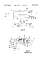
- FIG. 3 is a diagram of an automatic air recirculation system which is vacuum operated according to the principles of the present invention
- FIG. 4 is a diagram of an automatic air recirculation system which is electro-mechanically operated.
- FIG. 5 illustrates an exemplary air flow system for a vehicle air conditioning system having an air recirculation function.
- FIG. 3 illustrates a vacuum controlled automatic air recirculation system
- FIG. 4 illustrates an electro-mechanically actuated automatic air recirculation system
- the vacuum controlled automatic air recirculation system includes an engine electronic controller 100.
- Controller 100 receives a signal representative of the engine coolant temperature from an engine coolant temperature sensor 102.
- the engine electronic controller 100 provides an "On" output signal when the engine temperature reaches a predetermined temperature such as, for example, 230° F.
- the engine controller 100 also provides an "Off" output signal when the engine coolant temperature falls below a second predetermined temperature such as, for example, 210° F.
- the output signals generated by the engine electronic controller 100 are supplied to a vacuum solenoid 104 which is disposed in vacuum line 106.
- Vacuum line 106 is connected to vacuum reservoir 108 and vacuum source 110.
- Vacuum solenoid 104 provides a connection in line 106 for delivering vacuum pressure to the recirculating actuator 112.
- the air conditioning controller 114 disposed in line 116 is also provided with a valve 118 for connecting line 116 with recirculation actuator 112.
- a pressure switch 120 is also provided in the compressor discharge line 12 of the air conditioning system.
- Pressure switch 120 provides an "On" output signal to the vacuum solenoid 104 when the pressure in the compressor discharge line 12 exceeds a predetermined pressure, such as, for example 380 PSIG.
- Pressure switch 120 also provides an "Off" output signal when the pressure falls below a second predetermined pressure, such as, for example 285 PSIG.
- a predetermined pressure such as, for example 380 PSIG.
- Pressure switch 120 also provides an "Off" output signal when the pressure falls below a second predetermined pressure, such as, for example 285 PSIG.
- the first and second predetermined pressures will vary depending on design alternatives.
- the temperature in the compressor discharge line could also be used for determining when to actuate the recirculation door. In which case, pressure switch 120 would be replaced with a temperature switch (not shown).
- the automatic air recirculation system of the present invention is shown with an electromechanical actuator for opening the recirculation door.
- the engine electronic controller 100 and pressure switch 120 provide "On" “Off” output signals in response to predetermined temperatures and pressures, respectively as discussed above with reference to FIG. 3.
- the output signals are delivered to a relay switch 130 which when connected delivers a current to the recirculation door motor 132 via electrical line 134.
- the recirculation door motor 132 is thereby actuated to open or close the recirculation door 52.
- other known actuating devices could be utilized for opening and closing the recirculation door 52 without departing from the spirit and scope of the present invention.
- the described invention will automatically open the recirculation door of the air conditioning system when the engine coolant temperature or the compressor head pressure reach predetermined levels.
- the opening of the recirculation door will reduce the demand on the air conditioning system including reducing the head pressure in the compressor and condenser of the air conditioning system.
- the lower head pressure in the compressor reduces the stresses on the internal components of the compressor and improves the compressor volumetric efficiency by reducing compression ratio.
- the pressure on the refrigerant lines, couplings and connectors are also reduced.
- a reduction in the compressor head pressure also reduces the fuel consumption and exhaust emissions.
- the compressor brake horsepower can be decreased by about two BHP. This reduction contributes to emission reduction and fuel economy.
- the described invention also improves the vehicle occupant's comfort because lower internal air temperatures can be achieved quicker since cooler internal air is recirculated.
Abstract
Description
Claims (11)
Priority Applications (1)
| Application Number | Priority Date | Filing Date | Title |
|---|---|---|---|
| US08/789,359 US5749236A (en) | 1997-01-27 | 1997-01-27 | Automatic air recirculation system |
Applications Claiming Priority (1)
| Application Number | Priority Date | Filing Date | Title |
|---|---|---|---|
| US08/789,359 US5749236A (en) | 1997-01-27 | 1997-01-27 | Automatic air recirculation system |
Publications (1)
| Publication Number | Publication Date |
|---|---|
| US5749236A true US5749236A (en) | 1998-05-12 |
Family
ID=25147407
Family Applications (1)
| Application Number | Title | Priority Date | Filing Date |
|---|---|---|---|
| US08/789,359 Expired - Lifetime US5749236A (en) | 1997-01-27 | 1997-01-27 | Automatic air recirculation system |
Country Status (1)
| Country | Link |
|---|---|
| US (1) | US5749236A (en) |
Cited By (13)
| Publication number | Priority date | Publication date | Assignee | Title |
|---|---|---|---|---|
| US5992156A (en) * | 1997-11-04 | 1999-11-30 | Sanden Corporation | Air conditioning system for vehicles |
| US6134895A (en) * | 1997-10-21 | 2000-10-24 | Chrysler Corporation | Method of air conditioning system temperature control |
| US6341494B1 (en) | 1998-11-05 | 2002-01-29 | Sanden Corporation | Air conditioning system for vehicles |
| US6405545B1 (en) * | 2000-12-01 | 2002-06-18 | Visteon Global Technologies, Inc. | Heating ventilating and air conditioning system for vehicles |
| US6425253B1 (en) | 2000-06-02 | 2002-07-30 | Daimlerchrysler Corporation | Method for detecting low-charge condition in air conditioning system and device incorporating same |
| US6439329B1 (en) * | 1999-10-08 | 2002-08-27 | Ford Global Tech., Inc. | Integrated battery tray and reservoir assembly |
| US6595847B1 (en) | 1998-11-25 | 2003-07-22 | Thermo King Corporation | Automatic ambient air control system and method for refrigerated container |
| EP1566320A1 (en) * | 2004-02-18 | 2005-08-24 | Maurizio Walter Parisch | Flexible vacuum reservoir and connection element |
| US20050241326A1 (en) * | 2004-04-30 | 2005-11-03 | Thermo King Corporation | Temperature control unit having a vent arrangement |
| WO2007096033A1 (en) * | 2006-02-22 | 2007-08-30 | Volkswagen Aktiengesellschaft | Method for operating an air-conditioning system of a motor vehicle |
| USRE43429E1 (en) | 1998-11-25 | 2012-05-29 | Thermo King Corporation | Automatic ambient air control system and method for refrigerated container |
| US8893517B2 (en) | 2012-08-27 | 2014-11-25 | Ford Global Technologies, Llc | Vehicle air handling system |
| US9242531B2 (en) | 2012-03-15 | 2016-01-26 | Ford Global Technologies, Llc | Vehicle climate control method |
Citations (25)
| Publication number | Priority date | Publication date | Assignee | Title |
|---|---|---|---|---|
| US3315730A (en) * | 1964-12-21 | 1967-04-25 | Bendix Corp | Control system for automobile air conditioners |
| US3774676A (en) * | 1972-03-28 | 1973-11-27 | Eaton Corp | Automotive vehicle automatic temperature control system |
| US3983930A (en) * | 1973-09-24 | 1976-10-05 | Eaton Corporation | Temperature control system and multifunctional servomotor therefor |
| US4186564A (en) * | 1977-09-23 | 1980-02-05 | Melvin Myers | Air ventilation system |
| US4320628A (en) * | 1980-10-06 | 1982-03-23 | Nissan Motor Co., Ltd. | Quick air cooling system for use with automotive vehicle air conditioner |
| US4320797A (en) * | 1977-06-10 | 1982-03-23 | Hitachi, Ltd. | Control apparatus for air conditioner of automobile |
| US4328855A (en) * | 1978-10-20 | 1982-05-11 | Nippondenso Co., Ltd. | Method and apparatus for controlling automobile air conditioners |
| US4337818A (en) * | 1979-06-18 | 1982-07-06 | Eaton Corporation | Vehicle temperature control system |
| US4339076A (en) * | 1979-03-16 | 1982-07-13 | Aisin Seiki Kabushiki Kaisha | Control system for automobile air conditioners |
| US4365663A (en) * | 1980-01-16 | 1982-12-28 | Nippondenso Co., Ltd. | Method and system for controlling a vehicle-mounted air conditioner |
| US4391320A (en) * | 1979-07-24 | 1983-07-05 | Nippondenso Co., Ltd. | Method and an apparatus for air conditioning for vehicles by controlling circulation of inside air and introduction of outside air |
| US4490987A (en) * | 1983-12-05 | 1985-01-01 | General Motors Corporation | Vehicle air conditioning system |
| US4539823A (en) * | 1981-03-27 | 1985-09-10 | Nippondenso Co., Ltd. | Refrigeration system |
| US4616484A (en) * | 1984-11-30 | 1986-10-14 | Kysor Industrial Corporation | Vehicle refrigerant heating and cooling system |
| US4709751A (en) * | 1984-08-20 | 1987-12-01 | Nissan Motor Company, Limited | Vehicular air conditioner with defogging feature |
| US4802405A (en) * | 1985-08-21 | 1989-02-07 | Nippondenso Co., Ltd. | Automotive air-conditioner |
| US4841734A (en) * | 1987-11-12 | 1989-06-27 | Eaton Corporation | Indicating refrigerant liquid saturation point |
| US4865119A (en) * | 1986-02-04 | 1989-09-12 | Hitachi, Ltd. | Air conditioner system for automotive vehicles |
| US4913347A (en) * | 1988-07-21 | 1990-04-03 | Dr. Ing. H.C.F. Porsche Ag | Air-conditioning system for an air-cooled motor vehicle |
| US4914924A (en) * | 1987-07-17 | 1990-04-10 | Nissan Motor Co., Ltd. | Vehicle air conditioning system based on fuzzy inference |
| US4944160A (en) * | 1990-01-31 | 1990-07-31 | Eaton Corporation | Thermostatic expansion valve with electronic controller |
| US4974776A (en) * | 1988-07-04 | 1990-12-04 | Diesel Kiki Co., Ltd. | Apparatus for controlling air-mix door in automobile air-conditioners |
| US4996849A (en) * | 1988-10-31 | 1991-03-05 | Dr. Ing. H. C. F. Porsche Ag | Air conditioning system |
| US5284025A (en) * | 1991-06-17 | 1994-02-08 | Matsushita Electric Industrial Co., Ltd. | Air conditioning apparatus for an electrically-powered motor vehicle |
| US5590540A (en) * | 1994-07-06 | 1997-01-07 | Honda Giken Kogyo Kabushiki Kaisha | Air conditioner for vehicles |
-
1997
- 1997-01-27 US US08/789,359 patent/US5749236A/en not_active Expired - Lifetime
Patent Citations (25)
| Publication number | Priority date | Publication date | Assignee | Title |
|---|---|---|---|---|
| US3315730A (en) * | 1964-12-21 | 1967-04-25 | Bendix Corp | Control system for automobile air conditioners |
| US3774676A (en) * | 1972-03-28 | 1973-11-27 | Eaton Corp | Automotive vehicle automatic temperature control system |
| US3983930A (en) * | 1973-09-24 | 1976-10-05 | Eaton Corporation | Temperature control system and multifunctional servomotor therefor |
| US4320797A (en) * | 1977-06-10 | 1982-03-23 | Hitachi, Ltd. | Control apparatus for air conditioner of automobile |
| US4186564A (en) * | 1977-09-23 | 1980-02-05 | Melvin Myers | Air ventilation system |
| US4328855A (en) * | 1978-10-20 | 1982-05-11 | Nippondenso Co., Ltd. | Method and apparatus for controlling automobile air conditioners |
| US4339076A (en) * | 1979-03-16 | 1982-07-13 | Aisin Seiki Kabushiki Kaisha | Control system for automobile air conditioners |
| US4337818A (en) * | 1979-06-18 | 1982-07-06 | Eaton Corporation | Vehicle temperature control system |
| US4391320A (en) * | 1979-07-24 | 1983-07-05 | Nippondenso Co., Ltd. | Method and an apparatus for air conditioning for vehicles by controlling circulation of inside air and introduction of outside air |
| US4365663A (en) * | 1980-01-16 | 1982-12-28 | Nippondenso Co., Ltd. | Method and system for controlling a vehicle-mounted air conditioner |
| US4320628A (en) * | 1980-10-06 | 1982-03-23 | Nissan Motor Co., Ltd. | Quick air cooling system for use with automotive vehicle air conditioner |
| US4539823A (en) * | 1981-03-27 | 1985-09-10 | Nippondenso Co., Ltd. | Refrigeration system |
| US4490987A (en) * | 1983-12-05 | 1985-01-01 | General Motors Corporation | Vehicle air conditioning system |
| US4709751A (en) * | 1984-08-20 | 1987-12-01 | Nissan Motor Company, Limited | Vehicular air conditioner with defogging feature |
| US4616484A (en) * | 1984-11-30 | 1986-10-14 | Kysor Industrial Corporation | Vehicle refrigerant heating and cooling system |
| US4802405A (en) * | 1985-08-21 | 1989-02-07 | Nippondenso Co., Ltd. | Automotive air-conditioner |
| US4865119A (en) * | 1986-02-04 | 1989-09-12 | Hitachi, Ltd. | Air conditioner system for automotive vehicles |
| US4914924A (en) * | 1987-07-17 | 1990-04-10 | Nissan Motor Co., Ltd. | Vehicle air conditioning system based on fuzzy inference |
| US4841734A (en) * | 1987-11-12 | 1989-06-27 | Eaton Corporation | Indicating refrigerant liquid saturation point |
| US4974776A (en) * | 1988-07-04 | 1990-12-04 | Diesel Kiki Co., Ltd. | Apparatus for controlling air-mix door in automobile air-conditioners |
| US4913347A (en) * | 1988-07-21 | 1990-04-03 | Dr. Ing. H.C.F. Porsche Ag | Air-conditioning system for an air-cooled motor vehicle |
| US4996849A (en) * | 1988-10-31 | 1991-03-05 | Dr. Ing. H. C. F. Porsche Ag | Air conditioning system |
| US4944160A (en) * | 1990-01-31 | 1990-07-31 | Eaton Corporation | Thermostatic expansion valve with electronic controller |
| US5284025A (en) * | 1991-06-17 | 1994-02-08 | Matsushita Electric Industrial Co., Ltd. | Air conditioning apparatus for an electrically-powered motor vehicle |
| US5590540A (en) * | 1994-07-06 | 1997-01-07 | Honda Giken Kogyo Kabushiki Kaisha | Air conditioner for vehicles |
Cited By (16)
| Publication number | Priority date | Publication date | Assignee | Title |
|---|---|---|---|---|
| US6134895A (en) * | 1997-10-21 | 2000-10-24 | Chrysler Corporation | Method of air conditioning system temperature control |
| US5992156A (en) * | 1997-11-04 | 1999-11-30 | Sanden Corporation | Air conditioning system for vehicles |
| US6341494B1 (en) | 1998-11-05 | 2002-01-29 | Sanden Corporation | Air conditioning system for vehicles |
| USRE43429E1 (en) | 1998-11-25 | 2012-05-29 | Thermo King Corporation | Automatic ambient air control system and method for refrigerated container |
| US6595847B1 (en) | 1998-11-25 | 2003-07-22 | Thermo King Corporation | Automatic ambient air control system and method for refrigerated container |
| US6439329B1 (en) * | 1999-10-08 | 2002-08-27 | Ford Global Tech., Inc. | Integrated battery tray and reservoir assembly |
| US6425253B1 (en) | 2000-06-02 | 2002-07-30 | Daimlerchrysler Corporation | Method for detecting low-charge condition in air conditioning system and device incorporating same |
| US6405545B1 (en) * | 2000-12-01 | 2002-06-18 | Visteon Global Technologies, Inc. | Heating ventilating and air conditioning system for vehicles |
| EP1566320A1 (en) * | 2004-02-18 | 2005-08-24 | Maurizio Walter Parisch | Flexible vacuum reservoir and connection element |
| US20050241326A1 (en) * | 2004-04-30 | 2005-11-03 | Thermo King Corporation | Temperature control unit having a vent arrangement |
| US7171821B2 (en) | 2004-04-30 | 2007-02-06 | Thermo King Corporation | Temperature control unit having a vent arrangement |
| WO2007096033A1 (en) * | 2006-02-22 | 2007-08-30 | Volkswagen Aktiengesellschaft | Method for operating an air-conditioning system of a motor vehicle |
| US9242531B2 (en) | 2012-03-15 | 2016-01-26 | Ford Global Technologies, Llc | Vehicle climate control method |
| US9676249B2 (en) | 2012-03-15 | 2017-06-13 | Ford Global Technologies, Llc | Vehicle climate control method |
| US10953723B2 (en) | 2012-03-15 | 2021-03-23 | Ford Global Technologies, Llc | Vehicle climate control method |
| US8893517B2 (en) | 2012-08-27 | 2014-11-25 | Ford Global Technologies, Llc | Vehicle air handling system |
Similar Documents
| Publication | Publication Date | Title |
|---|---|---|
| US7152417B2 (en) | Battery cooling apparatus with sufficient cooling capacity | |
| KR100392622B1 (en) | Vehicular air conditioner | |
| US5749236A (en) | Automatic air recirculation system | |
| JP6138427B2 (en) | Heat pump air conditioning system for vehicles | |
| EP1512851B1 (en) | Method for controlling a valve for an exhaust system | |
| EP0788909B1 (en) | Air conditioner for vehicle | |
| US7562698B2 (en) | Vehicular air-conditioning system | |
| EP0913282B1 (en) | Heat pump type air conditioning system for automotive vehicle | |
| US20050072175A1 (en) | Air conditioner and truck equipped with same | |
| JP4682489B2 (en) | Air conditioner for vehicles | |
| US5560217A (en) | Air conditioning system of heat pump type | |
| KR20010007279A (en) | Vehicular air conditioner using heat pump | |
| CN112477543B (en) | Split type air conditioner for automobile | |
| US10046616B2 (en) | Air conditioning system for vehicle | |
| EP1295739B1 (en) | Combined heating and cooling system | |
| EP0681933B1 (en) | Air conditioning system of heat pump type | |
| US20070193292A1 (en) | Air conditioning system | |
| CN107584991B (en) | Air conditioning device for vehicle | |
| MXPA00003827A (en) | Air condenser, cooling fluid system and air-conditioning system in a vehicle. | |
| GB2343164A (en) | Cooling an electronic control unit in a vehicle | |
| EP0916914A2 (en) | A refrigerating cycle | |
| JP2000343934A (en) | Heat pump type vehicle air conditioner | |
| US10272735B2 (en) | Individual air conditioning apparatus for vehicle and method of controlling the same | |
| JPH1142934A (en) | Air conditioner | |
| US6134895A (en) | Method of air conditioning system temperature control |
Legal Events
| Date | Code | Title | Description |
|---|---|---|---|
| AS | Assignment |
Owner name: CHRYSLER CORPORATION, MICHIGAN Free format text: ASSIGNMENT OF ASSIGNORS INTEREST;ASSIGNORS:TAVIAN ARMANDO;KARGILIS, ALEXANDER;REEL/FRAME:008421/0446 Effective date: 19970122 |
|
| STCF | Information on status: patent grant |
Free format text: PATENTED CASE |
|
| FPAY | Fee payment |
Year of fee payment: 4 |
|
| REMI | Maintenance fee reminder mailed | ||
| AS | Assignment |
Owner name: SIEMENS VDO AUTOMOTIVE ELECTRONICS CORPORATION, AL Free format text: ASSIGNMENT OF ASSIGNORS INTEREST;ASSIGNOR:DAIMLERCHRYSLER CORPORATION;REEL/FRAME:016059/0722 Effective date: 20040401 |
|
| AS | Assignment |
Owner name: SIEMENS VDO AUTOMOTIVE ELECTRONICS CORPORATION, AL Free format text: ASSIGNMENT OF ASSIGNORS INTEREST;ASSIGNOR:DAIMLERCHRYSLER CORPORATION;REEL/FRAME:016216/0035 Effective date: 20040401 |
|
| FPAY | Fee payment |
Year of fee payment: 8 |
|
| AS | Assignment |
Owner name: DAIMLERCHRYSLER CORPORATION, MICHIGAN Free format text: CHANGE OF NAME;ASSIGNOR:CHRYSLER CORPORATION;REEL/FRAME:016800/0834 Effective date: 19981116 |
|
| AS | Assignment |
Owner name: WILMINGTON TRUST COMPANY, DELAWARE Free format text: GRANT OF SECURITY INTEREST IN PATENT RIGHTS - FIRST PRIORITY;ASSIGNOR:CHRYSLER LLC;REEL/FRAME:019773/0001 Effective date: 20070803 Owner name: WILMINGTON TRUST COMPANY,DELAWARE Free format text: GRANT OF SECURITY INTEREST IN PATENT RIGHTS - FIRST PRIORITY;ASSIGNOR:CHRYSLER LLC;REEL/FRAME:019773/0001 Effective date: 20070803 |
|
| AS | Assignment |
Owner name: WILMINGTON TRUST COMPANY, DELAWARE Free format text: GRANT OF SECURITY INTEREST IN PATENT RIGHTS - SECOND PRIORITY;ASSIGNOR:CHRYSLER LLC;REEL/FRAME:019767/0810 Effective date: 20070803 Owner name: WILMINGTON TRUST COMPANY,DELAWARE Free format text: GRANT OF SECURITY INTEREST IN PATENT RIGHTS - SECOND PRIORITY;ASSIGNOR:CHRYSLER LLC;REEL/FRAME:019767/0810 Effective date: 20070803 |
|
| AS | Assignment |
Owner name: US DEPARTMENT OF THE TREASURY, DISTRICT OF COLUMBI Free format text: GRANT OF SECURITY INTEREST IN PATENT RIGHTS - THIR;ASSIGNOR:CHRYSLER LLC;REEL/FRAME:022259/0188 Effective date: 20090102 Owner name: US DEPARTMENT OF THE TREASURY,DISTRICT OF COLUMBIA Free format text: GRANT OF SECURITY INTEREST IN PATENT RIGHTS - THIR;ASSIGNOR:CHRYSLER LLC;REEL/FRAME:022259/0188 Effective date: 20090102 |
|
| AS | Assignment |
Owner name: CHRYSLER LLC, MICHIGAN Free format text: RELEASE BY SECURED PARTY;ASSIGNOR:US DEPARTMENT OF THE TREASURY;REEL/FRAME:022902/0164 Effective date: 20090608 Owner name: CHRYSLER LLC,MICHIGAN Free format text: RELEASE BY SECURED PARTY;ASSIGNOR:US DEPARTMENT OF THE TREASURY;REEL/FRAME:022902/0164 Effective date: 20090608 |
|
| AS | Assignment |
Owner name: CHRYSLER LLC, MICHIGAN Free format text: RELEASE OF SECURITY INTEREST IN PATENT RIGHTS - FIRST PRIORITY;ASSIGNOR:WILMINGTON TRUST COMPANY;REEL/FRAME:022910/0498 Effective date: 20090604 Owner name: CHRYSLER LLC, MICHIGAN Free format text: RELEASE OF SECURITY INTEREST IN PATENT RIGHTS - SECOND PRIORITY;ASSIGNOR:WILMINGTON TRUST COMPANY;REEL/FRAME:022910/0740 Effective date: 20090604 Owner name: NEW CARCO ACQUISITION LLC, MICHIGAN Free format text: ASSIGNMENT OF ASSIGNORS INTEREST;ASSIGNOR:CHRYSLER LLC;REEL/FRAME:022915/0001 Effective date: 20090610 Owner name: THE UNITED STATES DEPARTMENT OF THE TREASURY, DIST Free format text: SECURITY AGREEMENT;ASSIGNOR:NEW CARCO ACQUISITION LLC;REEL/FRAME:022915/0489 Effective date: 20090610 Owner name: CHRYSLER LLC,MICHIGAN Free format text: RELEASE OF SECURITY INTEREST IN PATENT RIGHTS - FIRST PRIORITY;ASSIGNOR:WILMINGTON TRUST COMPANY;REEL/FRAME:022910/0498 Effective date: 20090604 Owner name: CHRYSLER LLC,MICHIGAN Free format text: RELEASE OF SECURITY INTEREST IN PATENT RIGHTS - SECOND PRIORITY;ASSIGNOR:WILMINGTON TRUST COMPANY;REEL/FRAME:022910/0740 Effective date: 20090604 Owner name: NEW CARCO ACQUISITION LLC,MICHIGAN Free format text: ASSIGNMENT OF ASSIGNORS INTEREST;ASSIGNOR:CHRYSLER LLC;REEL/FRAME:022915/0001 Effective date: 20090610 Owner name: THE UNITED STATES DEPARTMENT OF THE TREASURY,DISTR Free format text: SECURITY AGREEMENT;ASSIGNOR:NEW CARCO ACQUISITION LLC;REEL/FRAME:022915/0489 Effective date: 20090610 |
|
| AS | Assignment |
Owner name: CHRYSLER GROUP LLC, MICHIGAN Free format text: CHANGE OF NAME;ASSIGNOR:NEW CARCO ACQUISITION LLC;REEL/FRAME:022919/0126 Effective date: 20090610 Owner name: CHRYSLER GROUP LLC,MICHIGAN Free format text: CHANGE OF NAME;ASSIGNOR:NEW CARCO ACQUISITION LLC;REEL/FRAME:022919/0126 Effective date: 20090610 |
|
| FPAY | Fee payment |
Year of fee payment: 12 |
|
| AS | Assignment |
Owner name: CHRYSLER GROUP LLC, MICHIGAN Free format text: RELEASE BY SECURED PARTY;ASSIGNOR:THE UNITED STATES DEPARTMENT OF THE TREASURY;REEL/FRAME:026343/0298 Effective date: 20110524 Owner name: CHRYSLER GROUP GLOBAL ELECTRIC MOTORCARS LLC, NORT Free format text: RELEASE BY SECURED PARTY;ASSIGNOR:THE UNITED STATES DEPARTMENT OF THE TREASURY;REEL/FRAME:026343/0298 Effective date: 20110524 |
|
| AS | Assignment |
Owner name: CITIBANK, N.A., NEW YORK Free format text: SECURITY AGREEMENT;ASSIGNOR:CHRYSLER GROUP LLC;REEL/FRAME:026404/0123 Effective date: 20110524 |
|
| AS | Assignment |
Owner name: CITIBANK, N.A., NEW YORK Free format text: SECURITY AGREEMENT;ASSIGNOR:CHRYSLER GROUP LLC;REEL/FRAME:026435/0652 Effective date: 20110524 |
|
| AS | Assignment |
Owner name: DAIMLERCHRYSLER CORPORATION, MICHIGAN Free format text: CORRECTIVE ASSIGNMENT TO REMOVE PAT. NO. 5,754,794 PREVIOUSLY RECORDED ON PRIOR PATENT ASSIGNMENT PREVIOUSLY RECORDED ON REEL 016800 FRAME 0834. ASSIGNOR(S) HEREBY CONFIRMS THE CHANGE OF NAME;ASSIGNOR:CHRYSLER CORPORATION;REEL/FRAME:028640/0856 Effective date: 19981116 |
|
| AS | Assignment |
Owner name: JPMORGAN CHASE BANK, N.A., ILLINOIS Free format text: SECURITY AGREEMENT;ASSIGNOR:CHRYSLER GROUP LLC;REEL/FRAME:032384/0640 Effective date: 20140207 |
|
| AS | Assignment |
Owner name: FCA US LLC, MICHIGAN Free format text: CHANGE OF NAME;ASSIGNOR:CHRYSLER GROUP LLC;REEL/FRAME:035553/0356 Effective date: 20141203 |
|
| AS | Assignment |
Owner name: FCA US LLC, FORMERLY KNOWN AS CHRYSLER GROUP LLC, Free format text: RELEASE OF SECURITY INTEREST RELEASING SECOND-LIEN SECURITY INTEREST PREVIOUSLY RECORDED AT REEL 026426 AND FRAME 0644, REEL 026435 AND FRAME 0652, AND REEL 032384 AND FRAME 0591;ASSIGNOR:CITIBANK, N.A.;REEL/FRAME:037784/0001 Effective date: 20151221 |
|
| AS | Assignment |
Owner name: FCA US LLC (FORMERLY KNOWN AS CHRYSLER GROUP LLC), Free format text: RELEASE BY SECURED PARTY;ASSIGNOR:CITIBANK, N.A.;REEL/FRAME:042885/0255 Effective date: 20170224 |
|
| AS | Assignment |
Owner name: FCA US LLC (FORMERLY KNOWN AS CHRYSLER GROUP LLC), Free format text: RELEASE BY SECURED PARTY;ASSIGNOR:JPMORGAN CHASE BANK, N.A.;REEL/FRAME:048177/0356 Effective date: 20181113 |