US5757933A - In-the-ear hearing aid with directional microphone system - Google Patents
In-the-ear hearing aid with directional microphone system Download PDFInfo
- Publication number
- US5757933A US5757933A US08/763,520 US76352096A US5757933A US 5757933 A US5757933 A US 5757933A US 76352096 A US76352096 A US 76352096A US 5757933 A US5757933 A US 5757933A
- Authority
- US
- United States
- Prior art keywords
- hearing aid
- output signal
- directional
- microphone system
- directional microphone
- Prior art date
- Legal status (The legal status is an assumption and is not a legal conclusion. Google has not performed a legal analysis and makes no representation as to the accuracy of the status listed.)
- Expired - Lifetime
Links
Images


Classifications
-
- H—ELECTRICITY
- H04—ELECTRIC COMMUNICATION TECHNIQUE
- H04R—LOUDSPEAKERS, MICROPHONES, GRAMOPHONE PICK-UPS OR LIKE ACOUSTIC ELECTROMECHANICAL TRANSDUCERS; DEAF-AID SETS; PUBLIC ADDRESS SYSTEMS
- H04R29/00—Monitoring arrangements; Testing arrangements
- H04R29/004—Monitoring arrangements; Testing arrangements for microphones
- H04R29/005—Microphone arrays
-
- H—ELECTRICITY
- H04—ELECTRIC COMMUNICATION TECHNIQUE
- H04R—LOUDSPEAKERS, MICROPHONES, GRAMOPHONE PICK-UPS OR LIKE ACOUSTIC ELECTROMECHANICAL TRANSDUCERS; DEAF-AID SETS; PUBLIC ADDRESS SYSTEMS
- H04R25/00—Deaf-aid sets, i.e. electro-acoustic or electro-mechanical hearing aids; Electric tinnitus maskers providing an auditory perception
- H04R25/40—Arrangements for obtaining a desired directivity characteristic
- H04R25/407—Circuits for combining signals of a plurality of transducers
-
- H—ELECTRICITY
- H04—ELECTRIC COMMUNICATION TECHNIQUE
- H04R—LOUDSPEAKERS, MICROPHONES, GRAMOPHONE PICK-UPS OR LIKE ACOUSTIC ELECTROMECHANICAL TRANSDUCERS; DEAF-AID SETS; PUBLIC ADDRESS SYSTEMS
- H04R25/00—Deaf-aid sets, i.e. electro-acoustic or electro-mechanical hearing aids; Electric tinnitus maskers providing an auditory perception
- H04R25/55—Deaf-aid sets, i.e. electro-acoustic or electro-mechanical hearing aids; Electric tinnitus maskers providing an auditory perception using an external connection, either wireless or wired
- H04R25/552—Binaural
-
- H—ELECTRICITY
- H04—ELECTRIC COMMUNICATION TECHNIQUE
- H04R—LOUDSPEAKERS, MICROPHONES, GRAMOPHONE PICK-UPS OR LIKE ACOUSTIC ELECTROMECHANICAL TRANSDUCERS; DEAF-AID SETS; PUBLIC ADDRESS SYSTEMS
- H04R2225/00—Details of deaf aids covered by H04R25/00, not provided for in any of its subgroups
- H04R2225/025—In the ear hearing aids [ITE] hearing aids
-
- H—ELECTRICITY
- H04—ELECTRIC COMMUNICATION TECHNIQUE
- H04R—LOUDSPEAKERS, MICROPHONES, GRAMOPHONE PICK-UPS OR LIKE ACOUSTIC ELECTROMECHANICAL TRANSDUCERS; DEAF-AID SETS; PUBLIC ADDRESS SYSTEMS
- H04R2225/00—Details of deaf aids covered by H04R25/00, not provided for in any of its subgroups
- H04R2225/53—Hearing aid for unilateral hearing impairment using Contralateral Routing Of Signals [CROS]
-
- H—ELECTRICITY
- H04—ELECTRIC COMMUNICATION TECHNIQUE
- H04R—LOUDSPEAKERS, MICROPHONES, GRAMOPHONE PICK-UPS OR LIKE ACOUSTIC ELECTROMECHANICAL TRANSDUCERS; DEAF-AID SETS; PUBLIC ADDRESS SYSTEMS
- H04R25/00—Deaf-aid sets, i.e. electro-acoustic or electro-mechanical hearing aids; Electric tinnitus maskers providing an auditory perception
- H04R25/40—Arrangements for obtaining a desired directivity characteristic
- H04R25/405—Arrangements for obtaining a desired directivity characteristic by combining a plurality of transducers
-
- H—ELECTRICITY
- H04—ELECTRIC COMMUNICATION TECHNIQUE
- H04R—LOUDSPEAKERS, MICROPHONES, GRAMOPHONE PICK-UPS OR LIKE ACOUSTIC ELECTROMECHANICAL TRANSDUCERS; DEAF-AID SETS; PUBLIC ADDRESS SYSTEMS
- H04R29/00—Monitoring arrangements; Testing arrangements
- H04R29/004—Monitoring arrangements; Testing arrangements for microphones
- H04R29/005—Microphone arrays
- H04R29/006—Microphone matching
Definitions
- the present invention relates to a microphone system which may be used with an in-the-ear hearing aid system.
- the present invention relates to an adjustable microphone system, which may be used with an in-the-ear hearing aid, which allows the user to switch between a non-directional (or omni-direction) mode or a directional mode.
- Typical hearing aids either include a non-directional or directional hearing aid microphone system.
- a non-directional hearing aid system allows the user to pickup sounds from any direction. When a hearing aid user is trying to carry on a conversation within a crowded room, a non-directional hearing aid system does not allow the user to easily differentiate between the voice of the person the user is talking to and background or crowd noise.
- a directional hearing aid helps the user to hear the voice of the person they are having a conversation with, while reducing the miscellaneous crowd noise present within the room.
- directional hearing aids are implemented with a single microphone having inlets to cavities located in front and back of a diaphragm.
- Directionality with a single microphone is accomplished with an acoustic resistor placed across a hole in the back inlet of the microphone acting in combination with the compliance formed by the volume of air behind the diaphragm.
- This system is termed a first order pressure gradient directional microphone because the microphone output is a function of the pressure differential across the diaphragm.
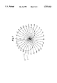
- the polar directivity pattern 10 shows the amount of pickup at a specific frequency (in terms of gain attenuation in dB) of a directional hearing aid system as a function of azimuth angle of sound incidence.
- Accurate measurement of a polar directivity pattern requires an anechoic chamber.
- An anechoic chamber is an enclosed room that has minimum reflection of sound from its inner wall surfaces and attenuates ambient sounds entering from the outside. Thus, inside an anechoic chamber, the direction of arrival of sound can be controlled so that it comes from only one specific angle of incidence.
- a cardioid or heart-shaped polar pattern (FIG. 1) produces a directivity index of about 3-4 dB.
- the directivity index is the ratio of energy arriving from in front of the hearing aid wearer to random energy incident from all directions around an imaginary sphere with the hearing aid at its center.
- a super cardioid polar pattern 14 as shown in FIG. 2, which can also be obtained with a first order gradient directional hearing aid microphone, produces a 5-6 dB directivity index. It has been found that producing a super-cardioid polar pattern 14 requires 1.72 times greater front-to-rear microphone inlet spacing than a cardioid polar pattern 12. The amount of space available for front-to-rear microphone spacing is limited by the physical size of the individual's ear. Because of limited space, a super cardioid directivity pattern is more difficult to achieve using a single directional microphone in a full-concha custom in-the-ear hearing aid device.
- behind-the-ear type hearing aids have included a main body and a hook extending from the main body and arrange to engage the upper end of the ear lobe of the user to hang the main body on the ear.
- Known versions of behind-the-hearing aids that had variable amounts of directionality use mechanical shutters or valves to adjust the amount of directionality. For example, see U.S. Pat. No. 3,798,390 to Gage et al.; U.S. Pat. No. 3,836,732 to Johanson et al.; and U.S. Pat. No. 4,051,330 to Cole.
- Other known behind-the-ear hearing aid systems such as U.S. Pat. No. 5,214,709 to Ribic suggests a behind-the-ear hearing aid system which includes the use of more than one non-directional microphone to make a directional microphone behind-the-ear hearing aid system.
- an in-the-ear hearing aid system which allows the user to switch between a non-directional (omni-directional) and a directional hearing aid mode. Further, it is desirable to have an in-the-ear hearing aid system having an adjustable directional microphone system, wherein the adjustable directional microphone system is adjustable between a cardioid polar directivity pattern and a super cardioid polar directivity pattern as required by the individual user. Further, it is desirable to have an in-the-ear hearing aid microphone system having an adjustable directional microphone system to allow compensation for small ears where the microphone inlets cannot be spaced far apart. It is also desirable to have an in-the-ear hearing aid microphone system which allows the in-the-ear hearing aid microphone system to be adjusted for manufacturing tolerances between the individual microphones.
- the present invention includes an apparatus for use as an in-the-ear hearing aid.
- the apparatus includes a housing having a shell and a face plate, wherein the shell is molded to custom fit a hearing aid user's ear.
- a first non-directional microphone system is included having a first inlet opening in the face plate for receiving sound, and having a first output signal representative of the sound received.
- a second non-directional microphone system is included having a second inlet opening in the face plate for receiving sound and having a second output signal representative of the sound received.
- a switch mechanism is provided having an operator extending through the housing for switching the in-the-ear hearing aid between a non-directional mode and a directional mode.
- the switch has an open position and a closed position.
- the in-the-ear hearing aid When the switch is in the closed position, the in-the-ear hearing aid operates in a directional mode.
- the switch is in an open position, the in-the-ear hearing aid operates in a non-directional mode.
- the apparatus may further include means for summing, selectively coupled to the first non-directional microphone system and the second non-directional microphone system, having a summed output signal representative of the sum of the first output signal and the second output signal.
- the means for summing may further comprise means for adjusting the polar directivity pattern of the summed output signal between a cardioid polar directivity pattern and a super cardioid polar directivity pattern.
- the means for adjusting the polar directivity pattern may include an inverting amplifier coupled to the second microphone system, and an adjustable low pass filter coupled to the inverting amplifier.
- the adjustable phase delay includes an adjustable phase delay having an adjustable capacitor.
- the means for adjusting the polar directivity may further include an adjustable amplifier coupled to the second microphone system.
- first inlet opening and the second inlet opening are relatively close together.
- first inlet opening and second inlet opening are less than 1/2 inch apart, and the first inlet opening and the second inlet opening are located in approximately the same line, which is generally horizontal to the ground when the in-the-ear hearing aid is located in a user's ear.
- the present invention includes a microphone system for use with an in-the-ear hearing aid.
- the system includes a first non-directional microphone system having a first inlet opening for receiving sound and having a first output signal representative of the sound received.
- a second non-directional microphone system is included having a second inlet opening for receiving sound having a second output signal representative of the sound received.
- Means are provided for coupling the first non-directional microphone system to the second non-directional microphone system for switching the in-the-ear hearing aid between a non-directional mode and a directional mode.
- the means for coupling may be a switch having a closed position and an open position, and wherein when the switch is in the open position, the in-the-ear hearing aid is in the non-directional mode, and when the switch is in a closed position, the in-the-ear hearing aid is in a directional mode.
- the second non-directional microphone system may further include means for inverting the second output signal.
- the second non-directional microphone system may further include means for adjusting the phase delay of the second output signal relative to the first output signal.
- the means for adjusting the phase delay may include a phase delay having an adjustable capacitor.
- the second non-directional microphone system may further include means for adjusting the amplitude of the first output signal relative to the second output signal.
- the present invention may include means for summing the first output signal and the second output signal.
- the means for summing may have an output coupled to an amplifier.
- the amplifier may include a phase delay.
- FIG. 1 is a cardioid polar directivity pattern of an in-the-ear hearing aid
- FIG. 2 is a super cardioid polar directivity pattern of an in-the-ear hearing aid
- FIG. 3 is a perspective view of an in-the-ear hearing aid in accordance with the present invention.
- FIG. 4 is a system block diagram of one embodiment of the hearing aid in accordance with the present invention.
- FIG. 5 is a schematic circuit diagram of one embodiment of the in-the-ear hearing aid in accordance with the present invention.
- an in-the-ear hearing aid is generally shown at 16.
- the in-the-ear (ITE) hearing aid 16 includes a housing 18 having a face plate 22 and a molded shell 20.
- the molded shell 20 is adhered to the face plate 22, indicated along line 24.
- the molded shell 20 is custom molded to fit each individual hearing aid wearer by known processes, such as making an impression of the individual hearing aid user's ear and forming the molded shell based on that impression.
- the face plate 22 is coupled to a circuit board (not shown) located inside the ITE hearing aid 16, which contains the circuitry for the hearing aid device.
- the battery door 26 allows the hearing aid user access to the in-the-ear hearing aid 16 for changing the battery (not shown).
- the volume control 28 allows the hearing aid user to adjust the volume or amplification level of the hearing aid 16.
- Switch S1 extends through the housing 18 and specifically face plate 22. Switch S1 allows the hearing aid user to manually switch the in-the-ear hearing aid 16 between a non-directional or directional hearing aid mode. Switch S1 is electronically coupled to the circuit contained within the in-the-ear hearing aid 16, which will be described in further detail later in the specification. With the novel idea of switch S1, a hearing aid user can switch to a non-directional hearing aid mode to hear sounds from all directions, or a directional hearing aid mode, such as for reducing background noise when carrying on a conversation in a crowded room.
- Microphone mic F and microphone mic B include inlet tubes 30, 32 which protrude through the in-the-ear hearing aid face plate 22. Microphone mic F and microphone mic B are spaced a relatively short distance apart, preferably less than 1 inch. In one preferred embodiment, microphone mic F and microphone mic B are preferably 7/16 of an inch apart (less than 1/2 an inch apart).
- An axis of directionality is defined by a line drawn through the inlet tube 30 and inlet tube 32 in face plate 22, indicated at 34.
- the in-the-ear hearing aid 16 in accordance with the present invention is of a molded design such that the axis of directionality 34 is relatively horizontal to the floor when the in-the-ear hearing aid 16 is positioned within the hearing aid 16 user's ear. With this design, optimum performance of the in-the-ear hearing aid 16 is achieved.
- the directional microphone system 36 utilizes two non-directional microphone circuits to achieve a directional microphone signal.
- the directional microphone system 36 includes a first non-directional microphone system 38 and a second non-directional microphone system 40.
- the output signals from the first non-directional microphone system 38 and second non-directional microphone system 40 may be electrically coupled through switch S1, and summed at node 46.
- the resulting output signal is indicated at 48.
- the output signal 48 is electrically coupled to a hearing aid circuit 50.
- the hearing aid circuit 50 may be a linear circuit, a compression circuit, an adaptive high-pass filter, and may include a high-power output stage.
- the in-the-ear hearing aid 16 may be switched between a non-directional mode and a directional mode through the operation of switch S1.
- switch S1 In the non-directional mode switch S1 is open (as shown), and non-directional microphone mic F feeds directly into hearing aid circuit 50.
- switch S1 For operation in a directional mode, switch S1 is closed, and the first non-directional microphone system 38 and second non-directional microphone system 40 output signals 42 and 44 are summed at summing node 46, with the resulting output signal 48 being coupled to hearing aid circuit 50.
- the second non-directional microphone system 40 includes non-directional microphone mic B, an inverter 52, an adjustable phase delay 54, and an adjustable gain 56.
- the output signal of microphone mic B is coupled to inverter 52, indicated at 58.
- the output signal of inverter 52 is coupled to the adjustable phase delay 54, indicated at 60.
- the output of adjustable phase delay 54 is coupled to the adjustable gain 56, indicated at 62.
- the output of the adjustable gain 56 is coupled to switch S1, indicated at 64.
- the output signal 58 of microphone mic B is inverted by inverter 52. Further, when switch S1 is closed, the adjustable phase delay 54 may be adjusted to adjust the phase delay of the output of mic B relative to the output of microphone mic F. Similarly, adjustable gain 56 adjusts the amplitude of the output signal received from mic B relative to the output signal 42 from microphone mic F.
- the hearing aid manufacturer and/or the hearing aid dispenser may vary the polar directivity pattern of the in-the-ear hearing aid from a cardioid polar pattern 12 (shown in FIG. 1) to a super cardioid polar pattern 14 (shown in FIG. 2), as desired by the individual hearing aid wearer.
- the adjustable non-directional microphone system 40 allows the cardioid pattern to be adjusted for compensation for small ears which do not allow larger inlet spacing. Further, the adjustable non-directional microphone system 40 allows for adjustments to compensate for the differences in manufacturing tolerances between non-directional microphone mic F and non-directional microphone mic B.
- the output signal 48 from first non-directional microphone system 38 and second non-directional microphone system 40 may be amplified by passing it through an amplifier 66.
- the resulting output signal of amplifier 66, indicated at 68, is coupled to the hearing aid circuit 50.
- Non-directional microphone mic F has a coupling capacitor Cl coupled to its output.
- Resistor R1 is electrically coupled between coupling capacitor C1 and summing node 46.
- Non-directional microphone mic B has a coupling capacitor C2 coupled to its output. Coupled to the output of C2 is inverter 52 with adjustable phase delay 54. The adjustable phase delay is an adjustable low pass filter.
- the inverter 52 is an operational amplifier OPAMP 1, shown in an inverting configuration. Coupled between capacitor C2 and the input node 70 of OPAMP 1 is resistor R2. Coupled between OPAMP 1 input node 70 and an OPAMP 1 output node 72 is resistor R3. Similarly, coupled between OPAMP 1 input node 70 and OPAMP 1 output node 72 is a capacitor C3.
- OPAMP 1 inverts the output signal received from non-directional microphone mic B. As such, when the output signal 42 and output signal 44 are summed at summing node 46, the signals are subtracted, resulting in output signal 48.
- the gain between the input of OPAMP 1 and the output of OPAMP 1 is indicated by the relationship R3/R2.
- R3 equals R2, resulting in a unity gain output signal from OPAMP 1.
- the phase delay 54 low pass filter capacitor C3 may be adjustable. By adjusting capacitor C3, the phase delay of the non-directional microphone mic B output relative to the non-directional microphone mic F may be adjusted. Coupled to the output node 72 of OPAMP 1 is a resistor R5 in series with an adjustable resistor or potentiometer R6. Further, coupled to output signal 48 is an inverting operational amplifier, OPAMP 2 having an input node 74 and an output node 76. Coupled between the input node 74 and the output node 76 is resistor R4. Also coupled between the input node 74 and the output node 76 is a capacitor C4. It is recognized that capacitor C4 and resistor R4 may also be adjustable.
- the resulting amplification or gain from the output from non-directional microphone mic F is the ratio of resistors R4/R1.
- the output gain contribution from mic B is determined by the ratio of R4/(R5 plus R6).
- the values for the circuit components shown in FIG. 5 are as follows:
- Non-directional microphone mic F and non-directional microphone mic B can be non-directional microphones as produced by Knowles No. EM5346.
- Operational amplifiers OPAMP 1 and OPAMP 2 may be inverting Gennum Hearing Aid Amplifiers No. 1/4 LX509.
- the hearing aid in accordance with the present invention allows a person wearing an in-the-ear hearing aid to switch between a non-directional mode and a directional mode by simple operation of switch S1 located on the in-the-ear hearing aid 16.
- the circuit components which makeup the directional microphone system 36 and the hearing aid circuit 50 are all located within the hearing aid housing 18 and coupled to the inside of face plate 22. Further, by adjustment of the adjustable phase delay 54 and adjustable gain 56, the directional microphone system 36 may be adjusted to vary the polar directivity pattern from cardioid to super cardioid.
- capacitor C4 and resistor R4 may be adjustable to compensate for each individual's hearing loss situation.
- the associated circuitry of the present invention allows the two non-directional microphones mic B and mic F to be positioned very close together and still produce a directional microphone system having a super cardioid polar directivity pattern.
- the directional microphone system in accordance with the present invention is able to space the two microphones less than one inch apart, and in a preferred embodiment, 7/16 of an inch apart in order for the directional microphone system in accordance with the present invention to be incorporated into an in-the-ear hearing aid device.
- the in-the-ear hearing aid 16 circuitry including the directional microphone system 36 circuitry and the hearing aid circuit 50 circuitry, utilize microcomponents and may further utilize printed circuit board technology to allow the directional microphone system 36 and hearing aid circuit 50 to be located within a single in-the-ear hearing aid 16.
Abstract
Description
              TABLE 1
______________________________________
            C1 = .01 μF
            C2 = .01 μF
            C3 = .0022 μF
            C4 = 110 pF
            R1 = 10K
            R2 = 10K
            R3 = 10K
            R4 = 1M
            R5 = 10K
            R6 = 2.2K
______________________________________
Claims (21)
Priority Applications (5)
| Application Number | Priority Date | Filing Date | Title |
|---|---|---|---|
| US08/763,520 US5757933A (en) | 1996-12-11 | 1996-12-11 | In-the-ear hearing aid with directional microphone system |
| CA002223676A CA2223676C (en) | 1996-12-11 | 1997-12-04 | In-the-ear hearing aid with directional microphone system |
| EP97403013A EP0848573A3 (en) | 1996-12-11 | 1997-12-11 | In-the-ear hearing aid with directional microphone system |
| US09/052,631 US6389142B1 (en) | 1996-12-11 | 1998-03-31 | In-the-ear hearing aid with directional microphone system |
| US10/094,592 US20020191805A1 (en) | 1996-12-11 | 2002-03-07 | In-the-ear hearing aid with directional microphone system |
Applications Claiming Priority (1)
| Application Number | Priority Date | Filing Date | Title |
|---|---|---|---|
| US08/763,520 US5757933A (en) | 1996-12-11 | 1996-12-11 | In-the-ear hearing aid with directional microphone system |
Related Child Applications (1)
| Application Number | Title | Priority Date | Filing Date |
|---|---|---|---|
| US09/052,631 Continuation-In-Part US6389142B1 (en) | 1996-12-11 | 1998-03-31 | In-the-ear hearing aid with directional microphone system |
Publications (1)
| Publication Number | Publication Date |
|---|---|
| US5757933A true US5757933A (en) | 1998-05-26 |
Family
ID=25068051
Family Applications (3)
| Application Number | Title | Priority Date | Filing Date |
|---|---|---|---|
| US08/763,520 Expired - Lifetime US5757933A (en) | 1996-12-11 | 1996-12-11 | In-the-ear hearing aid with directional microphone system |
| US09/052,631 Expired - Lifetime US6389142B1 (en) | 1996-12-11 | 1998-03-31 | In-the-ear hearing aid with directional microphone system |
| US10/094,592 Abandoned US20020191805A1 (en) | 1996-12-11 | 2002-03-07 | In-the-ear hearing aid with directional microphone system |
Family Applications After (2)
| Application Number | Title | Priority Date | Filing Date |
|---|---|---|---|
| US09/052,631 Expired - Lifetime US6389142B1 (en) | 1996-12-11 | 1998-03-31 | In-the-ear hearing aid with directional microphone system |
| US10/094,592 Abandoned US20020191805A1 (en) | 1996-12-11 | 2002-03-07 | In-the-ear hearing aid with directional microphone system |
Country Status (3)
| Country | Link |
|---|---|
| US (3) | US5757933A (en) |
| EP (1) | EP0848573A3 (en) |
| CA (1) | CA2223676C (en) |
Cited By (87)
| Publication number | Priority date | Publication date | Assignee | Title |
|---|---|---|---|---|
| WO2000032009A3 (en) * | 1998-11-25 | 2000-11-09 | Insonus Medical Inc | Semi-permanent canal hearing device |
| WO2000076268A2 (en) * | 1999-06-02 | 2000-12-14 | Siemens Audiologische Technik Gmbh | Hearing aid device, comprising a directional microphone system and a method for operating a hearing aid device |
| WO2001001731A1 (en) * | 1999-06-24 | 2001-01-04 | Widex A/S | A method for controlling the directionality of the sound receiving characteristic of a hearing aid and a hearing aid for carrying out the method |
| US6272229B1 (en) * | 1999-08-03 | 2001-08-07 | Topholm & Westermann Aps | Hearing aid with adaptive matching of microphones |
| US6285771B1 (en) * | 1996-12-31 | 2001-09-04 | Etymotic Research Inc. | Directional microphone assembly |
| WO2002003746A2 (en) * | 2000-06-30 | 2002-01-10 | Sonionmicrotronic Nederland B.V. | A microphone assembly |
| WO2002003750A2 (en) * | 2000-07-05 | 2002-01-10 | Gn Resound Corporation | Improved directional microphone system |
| US20020034310A1 (en) * | 2000-03-14 | 2002-03-21 | Audia Technology, Inc. | Adaptive microphone matching in multi-microphone directional system |
| US20020041696A1 (en) * | 2000-10-04 | 2002-04-11 | Topholm & Westermann Aps | Hearing aid with adaptive matching of input transducers |
| US20020067838A1 (en) * | 2000-12-05 | 2002-06-06 | Starkey Laboratories, Inc. | Digital automatic gain control |
| US6424721B1 (en) * | 1998-03-09 | 2002-07-23 | Siemens Audiologische Technik Gmbh | Hearing aid with a directional microphone system as well as method for the operation thereof |
| US20020168075A1 (en) * | 1997-01-13 | 2002-11-14 | Micro Ear Technology, Inc. | Portable system programming hearing aids |
| US6539096B1 (en) * | 1998-03-30 | 2003-03-25 | Siemens Audiologische Technik Gmbh | Method for producing a variable directional microphone characteristic and digital hearing aid operating according to the method |
| US20030059073A1 (en) * | 2000-09-11 | 2003-03-27 | Micro Ear Technology, Inc., D/B/A Micro-Tech | Integrated automatic telephone switch |
| US20030133578A1 (en) * | 2001-11-15 | 2003-07-17 | Durant Eric A. | Hearing aids and methods and apparatus for audio fitting thereof |
| US20030169891A1 (en) * | 2002-03-08 | 2003-09-11 | Ryan Jim G. | Low-noise directional microphone system |
| US6633645B2 (en) | 2000-09-11 | 2003-10-14 | Micro Ear Technology, Inc. | Automatic telephone switch for hearing aid |
| US20030215106A1 (en) * | 2002-05-15 | 2003-11-20 | Lawrence Hagen | Diotic presentation of second-order gradient directional hearing aid signals |
| US20030215105A1 (en) * | 2002-05-16 | 2003-11-20 | Sacha Mike K. | Hearing aid with time-varying performance |
| US20040028252A1 (en) * | 2002-04-17 | 2004-02-12 | Mcswiggen John P. | Acoustical switch for a directional microphone |
| US6704422B1 (en) | 2000-10-26 | 2004-03-09 | Widex A/S | Method for controlling the directionality of the sound receiving characteristic of a hearing aid a hearing aid for carrying out the method |
| US20040052392A1 (en) * | 2002-09-16 | 2004-03-18 | Sacha Mike K. | Switching structures for hearing aid |
| US20040052391A1 (en) * | 2002-09-12 | 2004-03-18 | Micro Ear Technology, Inc. | System and method for selectively coupling hearing aids to electromagnetic signals |
| US6714654B2 (en) | 2002-02-06 | 2004-03-30 | George Jay Lichtblau | Hearing aid operative to cancel sounds propagating through the hearing aid case |
| US6718301B1 (en) | 1998-11-11 | 2004-04-06 | Starkey Laboratories, Inc. | System for measuring speech content in sound |
| US20040081327A1 (en) * | 2001-04-18 | 2004-04-29 | Widex A/S | Hearing aid, a method of controlling a hearing aid, and a noise reduction system for a hearing aid |
| US6775389B2 (en) | 2001-08-10 | 2004-08-10 | Advanced Bionics Corporation | Ear auxiliary microphone for behind the ear hearing prosthetic |
| US6798890B2 (en) | 2000-10-05 | 2004-09-28 | Etymotic Research, Inc. | Directional microphone assembly |
| US20040252855A1 (en) * | 2003-06-16 | 2004-12-16 | Remir Vasserman | Hearing aid |
| US20050058309A1 (en) * | 2003-09-12 | 2005-03-17 | Poling John B. | Loudspeaker with single or dual channel input selector and lockout |
| WO2005027572A1 (en) * | 2003-09-09 | 2005-03-24 | King James T | Dual boundary pressure zone three dimensional microphone and hearing aid |
| US20050091060A1 (en) * | 2003-10-23 | 2005-04-28 | Wing Thomas W. | Hearing aid for increasing voice recognition through voice frequency downshift and/or voice substitution |
| US20050105749A1 (en) * | 2003-09-18 | 2005-05-19 | Torsten Niederdrank | Hearing device |
| US20050157895A1 (en) * | 2004-01-16 | 2005-07-21 | Lichtblau George J. | Hearing aid having acoustical feedback protection |
| US20050157897A1 (en) * | 2002-03-20 | 2005-07-21 | Oleg Saltykov | Hearing instrument |
| US6954535B1 (en) * | 1999-06-15 | 2005-10-11 | Siemens Audiologische Technik Gmbh | Method and adapting a hearing aid, and hearing aid with a directional microphone arrangement for implementing the method |
| US20060013420A1 (en) * | 2002-09-16 | 2006-01-19 | Sacha Michael K | Switching structures for hearing aid |
| US20060033277A1 (en) * | 1999-01-08 | 2006-02-16 | Dagoom, Inc. | Toy gaming equipment |
| US7006647B1 (en) * | 2000-02-11 | 2006-02-28 | Phonak Ag | Hearing aid with a microphone system and an analog/digital converter module |
| US7010136B1 (en) | 1999-02-17 | 2006-03-07 | Micro Ear Technology, Inc. | Resonant response matching circuit for hearing aid |
| US7031483B2 (en) | 1997-10-20 | 2006-04-18 | Technische Universiteit Delft | Hearing aid comprising an array of microphones |
| US7054957B2 (en) | 1997-01-13 | 2006-05-30 | Micro Ear Technology, Inc. | System for programming hearing aids |
| US7110553B1 (en) * | 1998-02-03 | 2006-09-19 | Etymotic Research, Inc. | Directional microphone assembly for mounting behind a surface |
| US20060218215A1 (en) * | 2005-03-23 | 2006-09-28 | Sanyo Electric Co., Ltd | Echo prevention circuit having adaptive digital filter |
| US20060218214A1 (en) * | 2005-03-23 | 2006-09-28 | Sanyo Electric Co., Ltd | Echo prevention circuit having signal subtracter feature |
| WO2006136615A2 (en) * | 2006-08-03 | 2006-12-28 | Phonak Ag | Method of adjusting a hearing instrument |
| US7162044B2 (en) | 1999-09-10 | 2007-01-09 | Starkey Laboratories, Inc. | Audio signal processing |
| US20070014419A1 (en) * | 2003-12-01 | 2007-01-18 | Dynamic Hearing Pty Ltd. | Method and apparatus for producing adaptive directional signals |
| US7242781B2 (en) | 2000-02-17 | 2007-07-10 | Apherma, Llc | Null adaptation in multi-microphone directional system |
| US20070177749A1 (en) * | 2006-01-30 | 2007-08-02 | Sjursen Walter P | Hearing aid circuit with integrated switch and battery |
| US20070189563A1 (en) * | 2006-01-30 | 2007-08-16 | Sjursen Walter P | Hearing aid with tuned microphone cavity |
| US20070186418A1 (en) * | 2006-02-10 | 2007-08-16 | Hilmar Meier | Method for manufacturing a hearing device and a use of the method |
| US20080008341A1 (en) * | 2006-07-10 | 2008-01-10 | Starkey Laboratories, Inc. | Method and apparatus for a binaural hearing assistance system using monaural audio signals |
| US20080101625A1 (en) * | 2006-10-27 | 2008-05-01 | Fazzio R Shane | Piezoelectric microphones |
| US20080118080A1 (en) * | 2006-11-22 | 2008-05-22 | General Motors Corporation | Method of recognizing speech from a plurality of speaking locations within a vehicle |
| US20080159548A1 (en) * | 2007-01-03 | 2008-07-03 | Starkey Laboratories, Inc. | Wireless system for hearing communication devices providing wireless stereo reception modes |
| US20080306745A1 (en) * | 2007-05-31 | 2008-12-11 | Ecole Polytechnique Federale De Lausanne | Distributed audio coding for wireless hearing aids |
| US20090034755A1 (en) * | 2002-03-21 | 2009-02-05 | Short Shannon M | Ambient noise cancellation for voice communications device |
| US20090094817A1 (en) * | 2007-10-11 | 2009-04-16 | Killion Mead C | Directional Microphone Assembly |
| EP2101514A1 (en) * | 2006-11-22 | 2009-09-16 | Funai Electric Advanced Applied Technology Research Institute Inc. | Voice input device, its manufacturing method and information processing system |
| US20100150385A1 (en) * | 2008-12-16 | 2010-06-17 | Siemens Audiologische Technik Gmbh | Hearing aid which can be worn in the ear with a directional microphone |
| US7787647B2 (en) | 1997-01-13 | 2010-08-31 | Micro Ear Technology, Inc. | Portable system for programming hearing aids |
| EP2282554A1 (en) * | 2008-05-20 | 2011-02-09 | Funai Electric Advanced Applied Technology Research Institute Inc. | Voice input device and manufacturing method thereof, and information processing system |
| US20110055120A1 (en) * | 2009-08-31 | 2011-03-03 | Starkey Laboratories, Inc. | Genetic algorithms with robust rank estimation for hearing assistance devices |
| US20110096945A1 (en) * | 2001-02-02 | 2011-04-28 | Fuerst Claus Erdmann | Microphone unit with internal A/D converter |
| US20110129108A1 (en) * | 2008-10-10 | 2011-06-02 | Knowles Electronics, Llc | Acoustic Valve Mechanisms |
| EP2506603A2 (en) | 2011-03-31 | 2012-10-03 | Siemens Medical Instruments Pte. Ltd. | Hearing aid with a directional microphone system and method for operating such a hearing aid device with said directional mocrophone system |
| US8300862B2 (en) | 2006-09-18 | 2012-10-30 | Starkey Kaboratories, Inc | Wireless interface for programming hearing assistance devices |
| US8503703B2 (en) | 2000-01-20 | 2013-08-06 | Starkey Laboratories, Inc. | Hearing aid systems |
| US20140119559A1 (en) * | 2006-07-08 | 2014-05-01 | Personics Holdings, Inc. | Personal audio assistant device and method |
| US8718288B2 (en) | 2007-12-14 | 2014-05-06 | Starkey Laboratories, Inc. | System for customizing hearing assistance devices |
| US8737653B2 (en) | 2009-12-30 | 2014-05-27 | Starkey Laboratories, Inc. | Noise reduction system for hearing assistance devices |
| US8965016B1 (en) | 2013-08-02 | 2015-02-24 | Starkey Laboratories, Inc. | Automatic hearing aid adaptation over time via mobile application |
| EP2373065B1 (en) | 2010-03-17 | 2016-01-13 | Sivantos Pte. Ltd. | Hearing aid and method for creating an omnidirectional alignment characteristic |
| US9763016B2 (en) | 2014-07-31 | 2017-09-12 | Starkey Laboratories, Inc. | Automatic directional switching algorithm for hearing aids |
| US9774961B2 (en) | 2005-06-05 | 2017-09-26 | Starkey Laboratories, Inc. | Hearing assistance device ear-to-ear communication using an intermediate device |
| US9859879B2 (en) | 2015-09-11 | 2018-01-02 | Knowles Electronics, Llc | Method and apparatus to clip incoming signals in opposing directions when in an off state |
| US10003379B2 (en) | 2014-05-06 | 2018-06-19 | Starkey Laboratories, Inc. | Wireless communication with probing bandwidth |
| US20180324522A1 (en) * | 2016-03-11 | 2018-11-08 | Panasonic Intellectual Property Management Co., Ltd. | Sound pressure gradient microphone |
| US10212682B2 (en) | 2009-12-21 | 2019-02-19 | Starkey Laboratories, Inc. | Low power intermittent messaging for hearing assistance devices |
| GB2575491A (en) * | 2018-07-12 | 2020-01-15 | Centricam Tech Limited | A microphone system |
| US10869141B2 (en) | 2018-01-08 | 2020-12-15 | Knowles Electronics, Llc | Audio device with valve state management |
| US10917731B2 (en) | 2018-12-31 | 2021-02-09 | Knowles Electronics, Llc | Acoustic valve for hearing device |
| US10932069B2 (en) | 2018-04-12 | 2021-02-23 | Knowles Electronics, Llc | Acoustic valve for hearing device |
| US10939217B2 (en) | 2017-12-29 | 2021-03-02 | Knowles Electronics, Llc | Audio device with acoustic valve |
| US11102576B2 (en) | 2018-12-31 | 2021-08-24 | Knowles Electronicis, LLC | Audio device with audio signal processing based on acoustic valve state |
| US11450331B2 (en) | 2006-07-08 | 2022-09-20 | Staton Techiya, Llc | Personal audio assistant device and method |
Families Citing this family (54)
| Publication number | Priority date | Publication date | Assignee | Title |
|---|---|---|---|---|
| US6978159B2 (en) * | 1996-06-19 | 2005-12-20 | Board Of Trustees Of The University Of Illinois | Binaural signal processing using multiple acoustic sensors and digital filtering |
| US6987856B1 (en) | 1996-06-19 | 2006-01-17 | Board Of Trustees Of The University Of Illinois | Binaural signal processing techniques |
| US7881486B1 (en) * | 1996-12-31 | 2011-02-01 | Etymotic Research, Inc. | Directional microphone assembly |
| US6278377B1 (en) | 1999-08-25 | 2001-08-21 | Donnelly Corporation | Indicator for vehicle accessory |
| DE19822021C2 (en) * | 1998-05-15 | 2000-12-14 | Siemens Audiologische Technik | Hearing aid with automatic microphone adjustment and method for operating a hearing aid with automatic microphone adjustment |
| US6654468B1 (en) * | 1998-08-25 | 2003-11-25 | Knowles Electronics, Llc | Apparatus and method for matching the response of microphones in magnitude and phase |
| EP1118248B1 (en) | 1998-09-29 | 2005-03-23 | Siemens Audiologische Technik GmbH | Hearing aid and method for processing microphone signals in a hearing aid |
| DE19849739C2 (en) * | 1998-10-28 | 2001-05-31 | Siemens Audiologische Technik | Adaptive method for correcting the microphones of a directional microphone system in a hearing aid and hearing aid |
| DK1017253T3 (en) * | 1998-12-30 | 2013-02-11 | Siemens Audiologische Technik | Blind source separation for hearing aids |
| DE19918883C1 (en) | 1999-04-26 | 2000-11-30 | Siemens Audiologische Technik | Obtaining directional microphone characteristic for hearing aid |
| US6876749B1 (en) * | 1999-07-12 | 2005-04-05 | Etymotic Research, Inc. | Microphone for hearing aid and communications applications having switchable polar and frequency response characteristics |
| US7447320B2 (en) * | 2001-02-14 | 2008-11-04 | Gentex Corporation | Vehicle accessory microphone |
| US8682005B2 (en) | 1999-11-19 | 2014-03-25 | Gentex Corporation | Vehicle accessory microphone |
| US6778674B1 (en) * | 1999-12-28 | 2004-08-17 | Texas Instruments Incorporated | Hearing assist device with directional detection and sound modification |
| EP1275267A2 (en) * | 2000-01-19 | 2003-01-15 | Microtronic Nederland B.V. | A directional microphone assembly |
| US7206423B1 (en) * | 2000-05-10 | 2007-04-17 | Board Of Trustees Of University Of Illinois | Intrabody communication for a hearing aid |
| WO2001087011A2 (en) * | 2000-05-10 | 2001-11-15 | The Board Of Trustees Of The University Of Illinois | Interference suppression techniques |
| US7346176B1 (en) * | 2000-05-11 | 2008-03-18 | Plantronics, Inc. | Auto-adjust noise canceling microphone with position sensor |
| AU2002250080A1 (en) * | 2001-02-14 | 2002-08-28 | Gentex Corporation | Vehicle accessory microphone |
| WO2003041447A1 (en) * | 2001-11-07 | 2003-05-15 | Oticon A/S | Microphone unit |
| US7512448B2 (en) | 2003-01-10 | 2009-03-31 | Phonak Ag | Electrode placement for wireless intrabody communication between components of a hearing system |
| US7286672B2 (en) * | 2003-03-07 | 2007-10-23 | Phonak Ag | Binaural hearing device and method for controlling a hearing device system |
| US8027495B2 (en) | 2003-03-07 | 2011-09-27 | Phonak Ag | Binaural hearing device and method for controlling a hearing device system |
| US20040175008A1 (en) * | 2003-03-07 | 2004-09-09 | Hans-Ueli Roeck | Method for producing control signals, method of controlling signal and a hearing device |
| DE10310579B4 (en) * | 2003-03-11 | 2005-06-16 | Siemens Audiologische Technik Gmbh | Automatic microphone adjustment for a directional microphone system with at least three microphones |
| US7945064B2 (en) * | 2003-04-09 | 2011-05-17 | Board Of Trustees Of The University Of Illinois | Intrabody communication with ultrasound |
| DE10327890A1 (en) * | 2003-06-20 | 2005-01-20 | Siemens Audiologische Technik Gmbh | Method for operating a hearing aid and hearing aid with a microphone system, in which different directional characteristics are adjustable |
| US7945056B2 (en) * | 2004-03-23 | 2011-05-17 | Oticon A/S | Listening device with two or more microphones |
| US7292591B2 (en) * | 2004-03-30 | 2007-11-06 | Extreme Networks, Inc. | Packet processing system architecture and method |
| US7903827B1 (en) | 2004-04-13 | 2011-03-08 | Sonic Innovations, Inc. | Hearing aid programming interface with configuration on demand |
| WO2006066570A1 (en) | 2004-12-22 | 2006-06-29 | Widex A/S | Bte hearing aid with customized shell and earplug |
| US20070041589A1 (en) * | 2005-08-17 | 2007-02-22 | Gennum Corporation | System and method for providing environmental specific noise reduction algorithms |
| US8068627B2 (en) * | 2006-03-14 | 2011-11-29 | Starkey Laboratories, Inc. | System for automatic reception enhancement of hearing assistance devices |
| US8494193B2 (en) * | 2006-03-14 | 2013-07-23 | Starkey Laboratories, Inc. | Environment detection and adaptation in hearing assistance devices |
| US8483416B2 (en) * | 2006-07-12 | 2013-07-09 | Phonak Ag | Methods for manufacturing audible signals |
| US8553897B2 (en) | 2009-06-09 | 2013-10-08 | Dean Robert Gary Anderson | Method and apparatus for directional acoustic fitting of hearing aids |
| US8879745B2 (en) * | 2009-07-23 | 2014-11-04 | Dean Robert Gary Anderson As Trustee Of The D/L Anderson Family Trust | Method of deriving individualized gain compensation curves for hearing aid fitting |
| US9101299B2 (en) * | 2009-07-23 | 2015-08-11 | Dean Robert Gary Anderson As Trustee Of The D/L Anderson Family Trust | Hearing aids configured for directional acoustic fitting |
| DK2346271T3 (en) * | 2009-12-01 | 2014-08-04 | Oticon As | Control of operating parameters in a binaural listening system |
| US9838784B2 (en) | 2009-12-02 | 2017-12-05 | Knowles Electronics, Llc | Directional audio capture |
| US8798290B1 (en) | 2010-04-21 | 2014-08-05 | Audience, Inc. | Systems and methods for adaptive signal equalization |
| US9558755B1 (en) | 2010-05-20 | 2017-01-31 | Knowles Electronics, Llc | Noise suppression assisted automatic speech recognition |
| WO2012138788A2 (en) * | 2011-04-05 | 2012-10-11 | Blue-Gear, Llc | Universal earpiece |
| US8942397B2 (en) | 2011-11-16 | 2015-01-27 | Dean Robert Gary Anderson | Method and apparatus for adding audible noise with time varying volume to audio devices |
| US9640194B1 (en) | 2012-10-04 | 2017-05-02 | Knowles Electronics, Llc | Noise suppression for speech processing based on machine-learning mask estimation |
| US8958586B2 (en) | 2012-12-21 | 2015-02-17 | Starkey Laboratories, Inc. | Sound environment classification by coordinated sensing using hearing assistance devices |
| US20140270291A1 (en) | 2013-03-15 | 2014-09-18 | Mark C. Flynn | Fitting a Bilateral Hearing Prosthesis System |
| US11412334B2 (en) * | 2013-10-23 | 2022-08-09 | Cochlear Limited | Contralateral sound capture with respect to stimulation energy source |
| DE112015003945T5 (en) | 2014-08-28 | 2017-05-11 | Knowles Electronics, Llc | Multi-source noise reduction |
| DE112015004185T5 (en) | 2014-09-12 | 2017-06-01 | Knowles Electronics, Llc | Systems and methods for recovering speech components |
| WO2016123560A1 (en) | 2015-01-30 | 2016-08-04 | Knowles Electronics, Llc | Contextual switching of microphones |
| US9554207B2 (en) * | 2015-04-30 | 2017-01-24 | Shure Acquisition Holdings, Inc. | Offset cartridge microphones |
| US10616691B2 (en) | 2015-11-12 | 2020-04-07 | Knowles Electronics, Llc | Method and apparatus to increase audio band microphone sensitivity |
| US10142742B2 (en) | 2016-01-01 | 2018-11-27 | Dean Robert Gary Anderson | Audio systems, devices, and methods |
Citations (19)
| Publication number | Priority date | Publication date | Assignee | Title |
|---|---|---|---|---|
| US3571514A (en) * | 1969-01-07 | 1971-03-16 | Zenith Radio Corp | Hearing aid tone control |
| US3770911A (en) * | 1972-07-21 | 1973-11-06 | Industrial Research Prod Inc | Hearing aid system |
| US3798390A (en) * | 1972-07-24 | 1974-03-19 | Gould Inc | Hearing aid with valved dual ports |
| US3836732A (en) * | 1972-09-07 | 1974-09-17 | Audivox Inc | Hearing aid having selectable directional characteristics |
| US3875349A (en) * | 1972-02-02 | 1975-04-01 | Bommer Ag | Hearing aid |
| US3946168A (en) * | 1974-09-16 | 1976-03-23 | Maico Hearing Instruments Inc. | Directional hearing aids |
| US3975599A (en) * | 1975-09-17 | 1976-08-17 | United States Surgical Corporation | Directional/non-directional hearing aid |
| US4051330A (en) * | 1975-06-23 | 1977-09-27 | Unitron Industries Ltd. | Hearing aid having adjustable directivity |
| US4142072A (en) * | 1976-11-29 | 1979-02-27 | Oticon Electronics A/S | Directional/omnidirectional hearing aid microphone with support |
| US4456795A (en) * | 1981-02-13 | 1984-06-26 | Rion Kabushiki Kaisha | Behind-the-ear type hearing aid |
| US4622440A (en) * | 1984-04-11 | 1986-11-11 | In Tech Systems Corp. | Differential hearing aid with programmable frequency response |
| US4712244A (en) * | 1985-10-16 | 1987-12-08 | Siemens Aktiengesellschaft | Directional microphone arrangement |
| US4723293A (en) * | 1983-07-01 | 1988-02-02 | Siemens Aktiengesellschaft | Hearing aid apparatus |
| US4751738A (en) * | 1984-11-29 | 1988-06-14 | The Board Of Trustees Of The Leland Stanford Junior University | Directional hearing aid |
| US5029215A (en) * | 1989-12-29 | 1991-07-02 | At&T Bell Laboratories | Automatic calibrating apparatus and method for second-order gradient microphone |
| US5214709A (en) * | 1990-07-13 | 1993-05-25 | Viennatone Gesellschaft M.B.H. | Hearing aid for persons with an impaired hearing faculty |
| US5226087A (en) * | 1991-04-18 | 1993-07-06 | Matsushita Electric Industrial Co., Ltd. | Microphone apparatus |
| US5289544A (en) * | 1991-12-31 | 1994-02-22 | Audiological Engineering Corporation | Method and apparatus for reducing background noise in communication systems and for enhancing binaural hearing systems for the hearing impaired |
| US5524056A (en) * | 1993-04-13 | 1996-06-04 | Etymotic Research, Inc. | Hearing aid having plural microphones and a microphone switching system |
Family Cites Families (2)
| Publication number | Priority date | Publication date | Assignee | Title |
|---|---|---|---|---|
| US4449018A (en) * | 1982-06-07 | 1984-05-15 | Stanton Austin N | Hearing aid |
| US5243660A (en) * | 1992-05-28 | 1993-09-07 | Zagorski Michael A | Directional microphone system |
-
1996
- 1996-12-11 US US08/763,520 patent/US5757933A/en not_active Expired - Lifetime
-
1997
- 1997-12-04 CA CA002223676A patent/CA2223676C/en not_active Expired - Fee Related
- 1997-12-11 EP EP97403013A patent/EP0848573A3/en not_active Withdrawn
-
1998
- 1998-03-31 US US09/052,631 patent/US6389142B1/en not_active Expired - Lifetime
-
2002
- 2002-03-07 US US10/094,592 patent/US20020191805A1/en not_active Abandoned
Patent Citations (19)
| Publication number | Priority date | Publication date | Assignee | Title |
|---|---|---|---|---|
| US3571514A (en) * | 1969-01-07 | 1971-03-16 | Zenith Radio Corp | Hearing aid tone control |
| US3875349A (en) * | 1972-02-02 | 1975-04-01 | Bommer Ag | Hearing aid |
| US3770911A (en) * | 1972-07-21 | 1973-11-06 | Industrial Research Prod Inc | Hearing aid system |
| US3798390A (en) * | 1972-07-24 | 1974-03-19 | Gould Inc | Hearing aid with valved dual ports |
| US3836732A (en) * | 1972-09-07 | 1974-09-17 | Audivox Inc | Hearing aid having selectable directional characteristics |
| US3946168A (en) * | 1974-09-16 | 1976-03-23 | Maico Hearing Instruments Inc. | Directional hearing aids |
| US4051330A (en) * | 1975-06-23 | 1977-09-27 | Unitron Industries Ltd. | Hearing aid having adjustable directivity |
| US3975599A (en) * | 1975-09-17 | 1976-08-17 | United States Surgical Corporation | Directional/non-directional hearing aid |
| US4142072A (en) * | 1976-11-29 | 1979-02-27 | Oticon Electronics A/S | Directional/omnidirectional hearing aid microphone with support |
| US4456795A (en) * | 1981-02-13 | 1984-06-26 | Rion Kabushiki Kaisha | Behind-the-ear type hearing aid |
| US4723293A (en) * | 1983-07-01 | 1988-02-02 | Siemens Aktiengesellschaft | Hearing aid apparatus |
| US4622440A (en) * | 1984-04-11 | 1986-11-11 | In Tech Systems Corp. | Differential hearing aid with programmable frequency response |
| US4751738A (en) * | 1984-11-29 | 1988-06-14 | The Board Of Trustees Of The Leland Stanford Junior University | Directional hearing aid |
| US4712244A (en) * | 1985-10-16 | 1987-12-08 | Siemens Aktiengesellschaft | Directional microphone arrangement |
| US5029215A (en) * | 1989-12-29 | 1991-07-02 | At&T Bell Laboratories | Automatic calibrating apparatus and method for second-order gradient microphone |
| US5214709A (en) * | 1990-07-13 | 1993-05-25 | Viennatone Gesellschaft M.B.H. | Hearing aid for persons with an impaired hearing faculty |
| US5226087A (en) * | 1991-04-18 | 1993-07-06 | Matsushita Electric Industrial Co., Ltd. | Microphone apparatus |
| US5289544A (en) * | 1991-12-31 | 1994-02-22 | Audiological Engineering Corporation | Method and apparatus for reducing background noise in communication systems and for enhancing binaural hearing systems for the hearing impaired |
| US5524056A (en) * | 1993-04-13 | 1996-06-04 | Etymotic Research, Inc. | Hearing aid having plural microphones and a microphone switching system |
Cited By (216)
| Publication number | Priority date | Publication date | Assignee | Title |
|---|---|---|---|---|
| US6285771B1 (en) * | 1996-12-31 | 2001-09-04 | Etymotic Research Inc. | Directional microphone assembly |
| US20040247146A1 (en) * | 1996-12-31 | 2004-12-09 | Killion Mead C. | Directional microphone assembly |
| US6831987B2 (en) * | 1996-12-31 | 2004-12-14 | Etymotic Research, Inc. | Directional microphone assembly |
| US6567526B1 (en) | 1996-12-31 | 2003-05-20 | Etymotic Research, Inc. | Directional microphone assembly |
| US7286677B2 (en) | 1996-12-31 | 2007-10-23 | Etymotic Research, Inc. | Directional microphone assembly |
| US7787647B2 (en) | 1997-01-13 | 2010-08-31 | Micro Ear Technology, Inc. | Portable system for programming hearing aids |
| US20020168075A1 (en) * | 1997-01-13 | 2002-11-14 | Micro Ear Technology, Inc. | Portable system programming hearing aids |
| US7929723B2 (en) | 1997-01-13 | 2011-04-19 | Micro Ear Technology, Inc. | Portable system for programming hearing aids |
| US7054957B2 (en) | 1997-01-13 | 2006-05-30 | Micro Ear Technology, Inc. | System for programming hearing aids |
| US7031483B2 (en) | 1997-10-20 | 2006-04-18 | Technische Universiteit Delft | Hearing aid comprising an array of microphones |
| US7110553B1 (en) * | 1998-02-03 | 2006-09-19 | Etymotic Research, Inc. | Directional microphone assembly for mounting behind a surface |
| US6424721B1 (en) * | 1998-03-09 | 2002-07-23 | Siemens Audiologische Technik Gmbh | Hearing aid with a directional microphone system as well as method for the operation thereof |
| US6539096B1 (en) * | 1998-03-30 | 2003-03-25 | Siemens Audiologische Technik Gmbh | Method for producing a variable directional microphone characteristic and digital hearing aid operating according to the method |
| US6718301B1 (en) | 1998-11-11 | 2004-04-06 | Starkey Laboratories, Inc. | System for measuring speech content in sound |
| WO2000032009A3 (en) * | 1998-11-25 | 2000-11-09 | Insonus Medical Inc | Semi-permanent canal hearing device |
| US20060033277A1 (en) * | 1999-01-08 | 2006-02-16 | Dagoom, Inc. | Toy gaming equipment |
| US7010136B1 (en) | 1999-02-17 | 2006-03-07 | Micro Ear Technology, Inc. | Resonant response matching circuit for hearing aid |
| US7324649B1 (en) | 1999-06-02 | 2008-01-29 | Siemens Audiologische Technik Gmbh | Hearing aid device, comprising a directional microphone system and a method for operating a hearing aid device |
| WO2000076268A3 (en) * | 1999-06-02 | 2001-05-17 | Siemens Audiologische Technik | Hearing aid device, comprising a directional microphone system and a method for operating a hearing aid device |
| WO2000076268A2 (en) * | 1999-06-02 | 2000-12-14 | Siemens Audiologische Technik Gmbh | Hearing aid device, comprising a directional microphone system and a method for operating a hearing aid device |
| US7929721B2 (en) | 1999-06-02 | 2011-04-19 | Siemens Audiologische Technik Gmbh | Hearing aid with directional microphone system, and method for operating a hearing aid |
| US20080044046A1 (en) * | 1999-06-02 | 2008-02-21 | Siemens Audiologische Technik Gmbh | Hearing aid with directional microphone system, and method for operating a hearing aid |
| US6954535B1 (en) * | 1999-06-15 | 2005-10-11 | Siemens Audiologische Technik Gmbh | Method and adapting a hearing aid, and hearing aid with a directional microphone arrangement for implementing the method |
| WO2001001731A1 (en) * | 1999-06-24 | 2001-01-04 | Widex A/S | A method for controlling the directionality of the sound receiving characteristic of a hearing aid and a hearing aid for carrying out the method |
| AU766876B2 (en) * | 1999-06-24 | 2003-10-23 | Widex A/S | A method for controlling the directionality of the sound receiving characteristic of a hearing aid and a hearing aid for carrying out the method |
| WO2001001732A1 (en) * | 1999-06-24 | 2001-01-04 | Tøpholm & Westermann APS | Hearing aid with controllable directional characteristics |
| US6272229B1 (en) * | 1999-08-03 | 2001-08-07 | Topholm & Westermann Aps | Hearing aid with adaptive matching of microphones |
| US7162044B2 (en) | 1999-09-10 | 2007-01-09 | Starkey Laboratories, Inc. | Audio signal processing |
| US9344817B2 (en) | 2000-01-20 | 2016-05-17 | Starkey Laboratories, Inc. | Hearing aid systems |
| US8503703B2 (en) | 2000-01-20 | 2013-08-06 | Starkey Laboratories, Inc. | Hearing aid systems |
| US9357317B2 (en) | 2000-01-20 | 2016-05-31 | Starkey Laboratories, Inc. | Hearing aid systems |
| US7006647B1 (en) * | 2000-02-11 | 2006-02-28 | Phonak Ag | Hearing aid with a microphone system and an analog/digital converter module |
| US7242781B2 (en) | 2000-02-17 | 2007-07-10 | Apherma, Llc | Null adaptation in multi-microphone directional system |
| US20020034310A1 (en) * | 2000-03-14 | 2002-03-21 | Audia Technology, Inc. | Adaptive microphone matching in multi-microphone directional system |
| US7155019B2 (en) | 2000-03-14 | 2006-12-26 | Apherma Corporation | Adaptive microphone matching in multi-microphone directional system |
| US7953241B2 (en) | 2000-06-30 | 2011-05-31 | Sonion Nederland B.V. | Microphone assembly |
| WO2002003746A2 (en) * | 2000-06-30 | 2002-01-10 | Sonionmicrotronic Nederland B.V. | A microphone assembly |
| WO2002003746A3 (en) * | 2000-06-30 | 2002-05-10 | Microtronic Nederland Bv | A microphone assembly |
| US20020009206A1 (en) * | 2000-06-30 | 2002-01-24 | Jorgensen Martin Bondo | Microphone assembly |
| WO2002003750A3 (en) * | 2000-07-05 | 2002-05-23 | Gn Resound Corp | Improved directional microphone system |
| US7116792B1 (en) | 2000-07-05 | 2006-10-03 | Gn Resound North America Corporation | Directional microphone system |
| WO2002003750A2 (en) * | 2000-07-05 | 2002-01-10 | Gn Resound Corporation | Improved directional microphone system |
| US7248713B2 (en) | 2000-09-11 | 2007-07-24 | Micro Bar Technology, Inc. | Integrated automatic telephone switch |
| US8259973B2 (en) | 2000-09-11 | 2012-09-04 | Micro Ear Technology, Inc. | Integrated automatic telephone switch |
| US20030059073A1 (en) * | 2000-09-11 | 2003-03-27 | Micro Ear Technology, Inc., D/B/A Micro-Tech | Integrated automatic telephone switch |
| US6633645B2 (en) | 2000-09-11 | 2003-10-14 | Micro Ear Technology, Inc. | Automatic telephone switch for hearing aid |
| US8923539B2 (en) | 2000-09-11 | 2014-12-30 | Starkey Laboratories, Inc. | Integrated automatic telephone switch |
| US6760457B1 (en) * | 2000-09-11 | 2004-07-06 | Micro Ear Technology, Inc. | Automatic telephone switch for hearing aid |
| US20020041696A1 (en) * | 2000-10-04 | 2002-04-11 | Topholm & Westermann Aps | Hearing aid with adaptive matching of input transducers |
| US6741714B2 (en) * | 2000-10-04 | 2004-05-25 | Widex A/S | Hearing aid with adaptive matching of input transducers |
| US6798890B2 (en) | 2000-10-05 | 2004-09-28 | Etymotic Research, Inc. | Directional microphone assembly |
| US6704422B1 (en) | 2000-10-26 | 2004-03-09 | Widex A/S | Method for controlling the directionality of the sound receiving characteristic of a hearing aid a hearing aid for carrying out the method |
| US9559653B2 (en) | 2000-12-05 | 2017-01-31 | K/S Himpp | Digital automatic gain control |
| US8009842B2 (en) | 2000-12-05 | 2011-08-30 | Semiconductor Components Industries, Llc | Hearing aid with digital compression recapture |
| US20020110253A1 (en) * | 2000-12-05 | 2002-08-15 | Garry Richardson | Hearing aid with digital compression recapture |
| US7489790B2 (en) | 2000-12-05 | 2009-02-10 | Ami Semiconductor, Inc. | Digital automatic gain control |
| US20070147639A1 (en) * | 2000-12-05 | 2007-06-28 | Starkey Laboratories, Inc. | Hearing aid with digital compression recapture |
| US20020067838A1 (en) * | 2000-12-05 | 2002-06-06 | Starkey Laboratories, Inc. | Digital automatic gain control |
| US20090208033A1 (en) * | 2000-12-05 | 2009-08-20 | Ami Semiconductor, Inc. | Digital automatic gain control |
| US7139403B2 (en) | 2000-12-05 | 2006-11-21 | Ami Semiconductor, Inc. | Hearing aid with digital compression recapture |
| US8649528B2 (en) | 2001-02-02 | 2014-02-11 | Techtronic A/S | Microphone unit with internal A/D converter |
| US20110096945A1 (en) * | 2001-02-02 | 2011-04-28 | Fuerst Claus Erdmann | Microphone unit with internal A/D converter |
| US7010134B2 (en) | 2001-04-18 | 2006-03-07 | Widex A/S | Hearing aid, a method of controlling a hearing aid, and a noise reduction system for a hearing aid |
| US20040081327A1 (en) * | 2001-04-18 | 2004-04-29 | Widex A/S | Hearing aid, a method of controlling a hearing aid, and a noise reduction system for a hearing aid |
| US7526096B2 (en) | 2001-08-10 | 2009-04-28 | Advanced Bionics, Llc | In the ear auxiliary microphone for behind the ear hearing prosthetic |
| US20070118011A1 (en) * | 2001-08-10 | 2007-05-24 | Advanced Bionics Corporation | In the ear auxiliary microphone system for behind the ear hearing prosthetic |
| US7769194B2 (en) | 2001-08-10 | 2010-08-03 | Advanced Bionics, Llc | In the ear auxiliary microphone for behind the ear hearing prosthetic |
| US8023677B2 (en) | 2001-08-10 | 2011-09-20 | Advanced Bionics, Llc | In the ear auxiliary microphone system for behind the ear hearing prosthetic |
| US7106873B1 (en) | 2001-08-10 | 2006-09-12 | Advanced Bionics Corporation | In the ear auxiliary microphone for behind the ear hearing prosthetic |
| US20070173683A1 (en) * | 2001-08-10 | 2007-07-26 | Advanced Bionics Corporation | In the ear auxiliary microphone system for behind the ear hearing prosthetic |
| US20070003089A1 (en) * | 2001-08-10 | 2007-01-04 | Advanced Bionics Corporation | In the ear auxiliary microphone for behind the ear hearing prosthetic |
| US20070001552A1 (en) * | 2001-08-10 | 2007-01-04 | Advanced Bionics Corporation | In the ear auxiliary microphone for behind the ear hearing prosthetic |
| US6775389B2 (en) | 2001-08-10 | 2004-08-10 | Advanced Bionics Corporation | Ear auxiliary microphone for behind the ear hearing prosthetic |
| US7003876B2 (en) | 2001-08-10 | 2006-02-28 | Advanced Bionics Corporation | Method of constructing an in the ear auxiliary microphone for behind the ear hearing prosthetic |
| US7167572B1 (en) | 2001-08-10 | 2007-01-23 | Advanced Bionics Corporation | In the ear auxiliary microphone system for behind the ear hearing prosthetic |
| US7970157B2 (en) | 2001-08-10 | 2011-06-28 | Advanced Bionics, Llc | In the ear auxiliary microphone system for behind the ear hearing prosthetic |
| US20030133578A1 (en) * | 2001-11-15 | 2003-07-17 | Durant Eric A. | Hearing aids and methods and apparatus for audio fitting thereof |
| US9049529B2 (en) | 2001-11-15 | 2015-06-02 | Starkey Laboratories, Inc. | Hearing aids and methods and apparatus for audio fitting thereof |
| US20100172524A1 (en) * | 2001-11-15 | 2010-07-08 | Starkey Laboratories, Inc. | Hearing aids and methods and apparatus for audio fitting thereof |
| US7650004B2 (en) | 2001-11-15 | 2010-01-19 | Starkey Laboratories, Inc. | Hearing aids and methods and apparatus for audio fitting thereof |
| US6714654B2 (en) | 2002-02-06 | 2004-03-30 | George Jay Lichtblau | Hearing aid operative to cancel sounds propagating through the hearing aid case |
| US20030169891A1 (en) * | 2002-03-08 | 2003-09-11 | Ryan Jim G. | Low-noise directional microphone system |
| EP1351544A2 (en) * | 2002-03-08 | 2003-10-08 | Gennum Corporation | Low-noise directional microphone system |
| EP1351544A3 (en) * | 2002-03-08 | 2008-03-19 | Gennum Corporation | Low-noise directional microphone system |
| US7409068B2 (en) | 2002-03-08 | 2008-08-05 | Sound Design Technologies, Ltd. | Low-noise directional microphone system |
| US20050157897A1 (en) * | 2002-03-20 | 2005-07-21 | Oleg Saltykov | Hearing instrument |
| US7245733B2 (en) | 2002-03-20 | 2007-07-17 | Siemens Hearing Instruments, Inc. | Hearing instrument microphone arrangement with improved sensitivity |
| US8472641B2 (en) * | 2002-03-21 | 2013-06-25 | At&T Intellectual Property I, L.P. | Ambient noise cancellation for voice communications device |
| US20090034755A1 (en) * | 2002-03-21 | 2009-02-05 | Short Shannon M | Ambient noise cancellation for voice communications device |
| US9369799B2 (en) | 2002-03-21 | 2016-06-14 | At&T Intellectual Property I, L.P. | Ambient noise cancellation for voice communication device |
| US9601102B2 (en) | 2002-03-21 | 2017-03-21 | At&T Intellectual Property I, L.P. | Ambient noise cancellation for voice communication device |
| US20040028252A1 (en) * | 2002-04-17 | 2004-02-12 | Mcswiggen John P. | Acoustical switch for a directional microphone |
| US7136497B2 (en) | 2002-04-17 | 2006-11-14 | Knowles Electronics, Llc. | Acoustical switch for a directional microphone |
| US20030215106A1 (en) * | 2002-05-15 | 2003-11-20 | Lawrence Hagen | Diotic presentation of second-order gradient directional hearing aid signals |
| US20080273727A1 (en) * | 2002-05-15 | 2008-11-06 | Micro Ear Technology, Inc., D/B/A Micro-Tech | Hearing assitance systems for providing second-order gradient directional signals |
| US7822217B2 (en) | 2002-05-15 | 2010-10-26 | Micro Ear Technology, Inc. | Hearing assistance systems for providing second-order gradient directional signals |
| US7369669B2 (en) | 2002-05-15 | 2008-05-06 | Micro Ear Technology, Inc. | Diotic presentation of second-order gradient directional hearing aid signals |
| US20030215105A1 (en) * | 2002-05-16 | 2003-11-20 | Sacha Mike K. | Hearing aid with time-varying performance |
| US6829363B2 (en) | 2002-05-16 | 2004-12-07 | Starkey Laboratories, Inc. | Hearing aid with time-varying performance |
| US20050254675A1 (en) * | 2002-05-16 | 2005-11-17 | Starkey Laboratories, Inc. | Hearing aid with time-varying performance |
| US7206424B2 (en) | 2002-05-16 | 2007-04-17 | Starkey Laboratories, Inc. | Hearing aid with time-varying performance |
| US7447325B2 (en) | 2002-09-12 | 2008-11-04 | Micro Ear Technology, Inc. | System and method for selectively coupling hearing aids to electromagnetic signals |
| US20040052391A1 (en) * | 2002-09-12 | 2004-03-18 | Micro Ear Technology, Inc. | System and method for selectively coupling hearing aids to electromagnetic signals |
| US8284970B2 (en) | 2002-09-16 | 2012-10-09 | Starkey Laboratories Inc. | Switching structures for hearing aid |
| US9215534B2 (en) | 2002-09-16 | 2015-12-15 | Starkey Laboratories, Inc. | Switching stuctures for hearing aid |
| US20060013420A1 (en) * | 2002-09-16 | 2006-01-19 | Sacha Michael K | Switching structures for hearing aid |
| US20040052392A1 (en) * | 2002-09-16 | 2004-03-18 | Sacha Mike K. | Switching structures for hearing aid |
| US8218804B2 (en) | 2002-09-16 | 2012-07-10 | Starkey Laboratories, Inc. | Switching structures for hearing assistance device |
| US7369671B2 (en) | 2002-09-16 | 2008-05-06 | Starkey, Laboratories, Inc. | Switching structures for hearing aid |
| US8971559B2 (en) | 2002-09-16 | 2015-03-03 | Starkey Laboratories, Inc. | Switching structures for hearing aid |
| US20070121975A1 (en) * | 2002-09-16 | 2007-05-31 | Starkey Laboratories. Inc. | Switching structures for hearing assistance device |
| US20080013769A1 (en) * | 2002-09-16 | 2008-01-17 | Starkey Laboratories, Inc. | Switching structures for hearing assistance device |
| US20080199030A1 (en) * | 2002-09-16 | 2008-08-21 | Starkey Laboratories, Inc. | Switching structures for hearing aid |
| US8433088B2 (en) | 2002-09-16 | 2013-04-30 | Starkey Laboratories, Inc. | Switching structures for hearing aid |
| US20040252855A1 (en) * | 2003-06-16 | 2004-12-16 | Remir Vasserman | Hearing aid |
| WO2005027572A1 (en) * | 2003-09-09 | 2005-03-24 | King James T | Dual boundary pressure zone three dimensional microphone and hearing aid |
| US7043034B2 (en) * | 2003-09-12 | 2006-05-09 | Britannia Investment Corporation | Loudspeaker with single or dual channel input selector and lockout |
| US20050058309A1 (en) * | 2003-09-12 | 2005-03-17 | Poling John B. | Loudspeaker with single or dual channel input selector and lockout |
| US7263194B2 (en) * | 2003-09-18 | 2007-08-28 | Siemens Audiologische Technik Gmbh | Hearing device |
| US20050105749A1 (en) * | 2003-09-18 | 2005-05-19 | Torsten Niederdrank | Hearing device |
| US20050091060A1 (en) * | 2003-10-23 | 2005-04-28 | Wing Thomas W. | Hearing aid for increasing voice recognition through voice frequency downshift and/or voice substitution |
| US8331582B2 (en) | 2003-12-01 | 2012-12-11 | Wolfson Dynamic Hearing Pty Ltd | Method and apparatus for producing adaptive directional signals |
| US20070014419A1 (en) * | 2003-12-01 | 2007-01-18 | Dynamic Hearing Pty Ltd. | Method and apparatus for producing adaptive directional signals |
| US20050157895A1 (en) * | 2004-01-16 | 2005-07-21 | Lichtblau George J. | Hearing aid having acoustical feedback protection |
| US7043037B2 (en) | 2004-01-16 | 2006-05-09 | George Jay Lichtblau | Hearing aid having acoustical feedback protection |
| US8934621B2 (en) * | 2005-03-23 | 2015-01-13 | Semiconductor Components Industries, Llc | Echo prevention circuit having signal subtracter feature |
| US20060218214A1 (en) * | 2005-03-23 | 2006-09-28 | Sanyo Electric Co., Ltd | Echo prevention circuit having signal subtracter feature |
| US20060218215A1 (en) * | 2005-03-23 | 2006-09-28 | Sanyo Electric Co., Ltd | Echo prevention circuit having adaptive digital filter |
| US8036376B2 (en) * | 2005-03-23 | 2011-10-11 | Semiconductor Components Industries, Llc | Echo prevention circuit having adaptive digital filter |
| TWI387230B (en) * | 2005-03-23 | 2013-02-21 | Sanyo Electric Co | An echo protection circuit, a digital signal processing circuit, and a filter coefficient setting method and program |
| US9774961B2 (en) | 2005-06-05 | 2017-09-26 | Starkey Laboratories, Inc. | Hearing assistance device ear-to-ear communication using an intermediate device |
| US8121326B2 (en) | 2006-01-30 | 2012-02-21 | K/S Himpp | Hearing aid |
| US20100119094A1 (en) * | 2006-01-30 | 2010-05-13 | Songbird Hearing, Inc. | Hearing aid |
| US20100098280A1 (en) * | 2006-01-30 | 2010-04-22 | Songbird Hearing, Inc. | Hearing aid |
| US7756285B2 (en) | 2006-01-30 | 2010-07-13 | Songbird Hearing, Inc. | Hearing aid with tuned microphone cavity |
| US20070189563A1 (en) * | 2006-01-30 | 2007-08-16 | Sjursen Walter P | Hearing aid with tuned microphone cavity |
| US7756284B2 (en) | 2006-01-30 | 2010-07-13 | Songbird Hearing, Inc. | Hearing aid circuit with integrated switch and battery |
| US20070177749A1 (en) * | 2006-01-30 | 2007-08-02 | Sjursen Walter P | Hearing aid circuit with integrated switch and battery |
| US8121327B2 (en) | 2006-01-30 | 2012-02-21 | K/S Himpp | Hearing aid |
| US20070186418A1 (en) * | 2006-02-10 | 2007-08-16 | Hilmar Meier | Method for manufacturing a hearing device and a use of the method |
| US10236011B2 (en) | 2006-07-08 | 2019-03-19 | Staton Techiya, Llc | Personal audio assistant device and method |
| US10971167B2 (en) | 2006-07-08 | 2021-04-06 | Staton Techiya, Llc | Personal audio assistant device and method |
| US20140119559A1 (en) * | 2006-07-08 | 2014-05-01 | Personics Holdings, Inc. | Personal audio assistant device and method |
| US10410649B2 (en) | 2006-07-08 | 2019-09-10 | Station Techiya, LLC | Personal audio assistant device and method |
| US10311887B2 (en) | 2006-07-08 | 2019-06-04 | Staton Techiya, Llc | Personal audio assistant device and method |
| US10885927B2 (en) | 2006-07-08 | 2021-01-05 | Staton Techiya, Llc | Personal audio assistant device and method |
| US10297265B2 (en) | 2006-07-08 | 2019-05-21 | Staton Techiya, Llc | Personal audio assistant device and method |
| US11450331B2 (en) | 2006-07-08 | 2022-09-20 | Staton Techiya, Llc | Personal audio assistant device and method |
| US10236013B2 (en) * | 2006-07-08 | 2019-03-19 | Staton Techiya, Llc | Personal audio assistant device and method |
| US10236012B2 (en) | 2006-07-08 | 2019-03-19 | Staton Techiya, Llc | Personal audio assistant device and method |
| US10629219B2 (en) | 2006-07-08 | 2020-04-21 | Staton Techiya, Llc | Personal audio assistant device and method |
| US10469960B2 (en) | 2006-07-10 | 2019-11-05 | Starkey Laboratories, Inc. | Method and apparatus for a binaural hearing assistance system using monaural audio signals |
| US9510111B2 (en) | 2006-07-10 | 2016-11-29 | Starkey Laboratories, Inc. | Method and apparatus for a binaural hearing assistance system using monaural audio signals |
| US9036823B2 (en) | 2006-07-10 | 2015-05-19 | Starkey Laboratories, Inc. | Method and apparatus for a binaural hearing assistance system using monaural audio signals |
| US10728678B2 (en) | 2006-07-10 | 2020-07-28 | Starkey Laboratories, Inc. | Method and apparatus for a binaural hearing assistance system using monaural audio signals |
| US8208642B2 (en) | 2006-07-10 | 2012-06-26 | Starkey Laboratories, Inc. | Method and apparatus for a binaural hearing assistance system using monaural audio signals |
| US10051385B2 (en) | 2006-07-10 | 2018-08-14 | Starkey Laboratories, Inc. | Method and apparatus for a binaural hearing assistance system using monaural audio signals |
| US20080008341A1 (en) * | 2006-07-10 | 2008-01-10 | Starkey Laboratories, Inc. | Method and apparatus for a binaural hearing assistance system using monaural audio signals |
| US11064302B2 (en) | 2006-07-10 | 2021-07-13 | Starkey Laboratories, Inc. | Method and apparatus for a binaural hearing assistance system using monaural audio signals |
| US11678128B2 (en) | 2006-07-10 | 2023-06-13 | Starkey Laboratories, Inc. | Method and apparatus for a binaural hearing assistance system using monaural audio signals |
| WO2006136615A3 (en) * | 2006-08-03 | 2007-08-02 | Phonak Ag | Method of adjusting a hearing instrument |
| WO2006136615A2 (en) * | 2006-08-03 | 2006-12-28 | Phonak Ag | Method of adjusting a hearing instrument |
| US8300862B2 (en) | 2006-09-18 | 2012-10-30 | Starkey Kaboratories, Inc | Wireless interface for programming hearing assistance devices |
| US20080101625A1 (en) * | 2006-10-27 | 2008-05-01 | Fazzio R Shane | Piezoelectric microphones |
| US8369555B2 (en) * | 2006-10-27 | 2013-02-05 | Avago Technologies Wireless Ip (Singapore) Pte. Ltd. | Piezoelectric microphones |
| EP2101514A1 (en) * | 2006-11-22 | 2009-09-16 | Funai Electric Advanced Applied Technology Research Institute Inc. | Voice input device, its manufacturing method and information processing system |
| US8054990B2 (en) * | 2006-11-22 | 2011-11-08 | General Motors Llc | Method of recognizing speech from a plurality of speaking locations within a vehicle |
| EP2101514A4 (en) * | 2006-11-22 | 2011-09-28 | Funai Eaa Tech Res Inst Inc | Voice input device, its manufacturing method and information processing system |
| US8638955B2 (en) | 2006-11-22 | 2014-01-28 | Funai Electric Advanced Applied Technology Research Institute Inc. | Voice input device, method of producing the same, and information processing system |
| US20080118080A1 (en) * | 2006-11-22 | 2008-05-22 | General Motors Corporation | Method of recognizing speech from a plurality of speaking locations within a vehicle |
| US20100260346A1 (en) * | 2006-11-22 | 2010-10-14 | Funai Electric Co., Ltd | Voice Input Device, Method of Producing the Same, and Information Processing System |
| US11765526B2 (en) | 2007-01-03 | 2023-09-19 | Starkey Laboratories, Inc. | Wireless system for hearing communication devices providing wireless stereo reception modes |
| US11218815B2 (en) | 2007-01-03 | 2022-01-04 | Starkey Laboratories, Inc. | Wireless system for hearing communication devices providing wireless stereo reception modes |
| US8041066B2 (en) | 2007-01-03 | 2011-10-18 | Starkey Laboratories, Inc. | Wireless system for hearing communication devices providing wireless stereo reception modes |
| US9282416B2 (en) | 2007-01-03 | 2016-03-08 | Starkey Laboratories, Inc. | Wireless system for hearing communication devices providing wireless stereo reception modes |
| US9854369B2 (en) | 2007-01-03 | 2017-12-26 | Starkey Laboratories, Inc. | Wireless system for hearing communication devices providing wireless stereo reception modes |
| US20080159548A1 (en) * | 2007-01-03 | 2008-07-03 | Starkey Laboratories, Inc. | Wireless system for hearing communication devices providing wireless stereo reception modes |
| US8515114B2 (en) | 2007-01-03 | 2013-08-20 | Starkey Laboratories, Inc. | Wireless system for hearing communication devices providing wireless stereo reception modes |
| US10511918B2 (en) | 2007-01-03 | 2019-12-17 | Starkey Laboratories, Inc. | Wireless system for hearing communication devices providing wireless stereo reception modes |
| US8077893B2 (en) * | 2007-05-31 | 2011-12-13 | Ecole Polytechnique Federale De Lausanne | Distributed audio coding for wireless hearing aids |
| US20080306745A1 (en) * | 2007-05-31 | 2008-12-11 | Ecole Polytechnique Federale De Lausanne | Distributed audio coding for wireless hearing aids |
| US7832080B2 (en) | 2007-10-11 | 2010-11-16 | Etymotic Research, Inc. | Directional microphone assembly |
| US20090094817A1 (en) * | 2007-10-11 | 2009-04-16 | Killion Mead C | Directional Microphone Assembly |
| US8718288B2 (en) | 2007-12-14 | 2014-05-06 | Starkey Laboratories, Inc. | System for customizing hearing assistance devices |
| US20110158454A1 (en) * | 2008-05-20 | 2011-06-30 | Funai Electric Co., Ltd. | Voice input device, method for manufacturing the same, and information processing system |
| EP2282554A1 (en) * | 2008-05-20 | 2011-02-09 | Funai Electric Advanced Applied Technology Research Institute Inc. | Voice input device and manufacturing method thereof, and information processing system |
| US8774429B2 (en) | 2008-05-20 | 2014-07-08 | Funai Electric Advanced Applied Technology Research Institute Inc. | Voice input device, method for manufacturing the same, and information processing system |
| EP2282554A4 (en) * | 2008-05-20 | 2012-01-18 | Funai Eaa Tech Res Inst Inc | Voice input device and manufacturing method thereof, and information processing system |
| US20110129108A1 (en) * | 2008-10-10 | 2011-06-02 | Knowles Electronics, Llc | Acoustic Valve Mechanisms |
| US8798304B2 (en) | 2008-10-10 | 2014-08-05 | Knowles Electronics, Llc | Acoustic valve mechanisms |
| EP2200343A1 (en) | 2008-12-16 | 2010-06-23 | Siemens Audiologische Technik GmbH | Hearing aid with directional microphone |
| US20100150385A1 (en) * | 2008-12-16 | 2010-06-17 | Siemens Audiologische Technik Gmbh | Hearing aid which can be worn in the ear with a directional microphone |
| US8359283B2 (en) | 2009-08-31 | 2013-01-22 | Starkey Laboratories, Inc. | Genetic algorithms with robust rank estimation for hearing assistance devices |
| US20110055120A1 (en) * | 2009-08-31 | 2011-03-03 | Starkey Laboratories, Inc. | Genetic algorithms with robust rank estimation for hearing assistance devices |
| US10212682B2 (en) | 2009-12-21 | 2019-02-19 | Starkey Laboratories, Inc. | Low power intermittent messaging for hearing assistance devices |
| US11019589B2 (en) | 2009-12-21 | 2021-05-25 | Starkey Laboratories, Inc. | Low power intermittent messaging for hearing assistance devices |
| US9204227B2 (en) | 2009-12-30 | 2015-12-01 | Starkey Laboratories, Inc. | Noise reduction system for hearing assistance devices |
| US8737653B2 (en) | 2009-12-30 | 2014-05-27 | Starkey Laboratories, Inc. | Noise reduction system for hearing assistance devices |
| EP2373065B2 (en) † | 2010-03-17 | 2018-10-03 | Sivantos Pte. Ltd. | Hearing aid and method for creating an omnidirectional alignment characteristic |
| EP2373065B1 (en) | 2010-03-17 | 2016-01-13 | Sivantos Pte. Ltd. | Hearing aid and method for creating an omnidirectional alignment characteristic |
| DE102011006471B4 (en) * | 2011-03-31 | 2013-08-08 | Siemens Medical Instruments Pte. Ltd. | Hearing aid device and hearing aid system with a directional microphone system and method for adjusting a directional microphone in a hearing aid |
| EP2506603A2 (en) | 2011-03-31 | 2012-10-03 | Siemens Medical Instruments Pte. Ltd. | Hearing aid with a directional microphone system and method for operating such a hearing aid device with said directional mocrophone system |
| DE102011006471A1 (en) | 2011-03-31 | 2012-10-04 | Siemens Medical Instruments Pte. Ltd. | Hearing aid with a directional microphone system and method for setting a directional microphone in a hearing aid |
| US9060232B2 (en) | 2011-03-31 | 2015-06-16 | Siemens Medical Instruments Pte. Ltd. | Hearing aid device with a directional microphone system and method for operating a hearing aid device having a directional microphone system |
| US8965016B1 (en) | 2013-08-02 | 2015-02-24 | Starkey Laboratories, Inc. | Automatic hearing aid adaptation over time via mobile application |
| US10003379B2 (en) | 2014-05-06 | 2018-06-19 | Starkey Laboratories, Inc. | Wireless communication with probing bandwidth |
| US9763016B2 (en) | 2014-07-31 | 2017-09-12 | Starkey Laboratories, Inc. | Automatic directional switching algorithm for hearing aids |
| US9859879B2 (en) | 2015-09-11 | 2018-01-02 | Knowles Electronics, Llc | Method and apparatus to clip incoming signals in opposing directions when in an off state |
| US10499145B2 (en) * | 2016-03-11 | 2019-12-03 | Panasonic Intellectual Property Management Co., Ltd. | Sound pressure gradient microphone |
| US20180324522A1 (en) * | 2016-03-11 | 2018-11-08 | Panasonic Intellectual Property Management Co., Ltd. | Sound pressure gradient microphone |
| US10939217B2 (en) | 2017-12-29 | 2021-03-02 | Knowles Electronics, Llc | Audio device with acoustic valve |
| US10869141B2 (en) | 2018-01-08 | 2020-12-15 | Knowles Electronics, Llc | Audio device with valve state management |
| US10932069B2 (en) | 2018-04-12 | 2021-02-23 | Knowles Electronics, Llc | Acoustic valve for hearing device |
| GB2575491A (en) * | 2018-07-12 | 2020-01-15 | Centricam Tech Limited | A microphone system |
| US10917731B2 (en) | 2018-12-31 | 2021-02-09 | Knowles Electronics, Llc | Acoustic valve for hearing device |
| US11102576B2 (en) | 2018-12-31 | 2021-08-24 | Knowles Electronicis, LLC | Audio device with audio signal processing based on acoustic valve state |
Also Published As
| Publication number | Publication date |
|---|---|
| US6389142B1 (en) | 2002-05-14 |
| CA2223676A1 (en) | 1998-06-11 |
| CA2223676C (en) | 2004-11-23 |
| EP0848573A2 (en) | 1998-06-17 |
| US20020191805A1 (en) | 2002-12-19 |
| EP0848573A3 (en) | 2001-11-07 |
Similar Documents
| Publication | Publication Date | Title |
|---|---|---|
| US5757933A (en) | In-the-ear hearing aid with directional microphone system | |
| US6134334A (en) | Directional microphone assembly | |
| US7822217B2 (en) | Hearing assistance systems for providing second-order gradient directional signals | |
| US6151399A (en) | Directional microphone system providing for ease of assembly and disassembly | |
| US7881486B1 (en) | Directional microphone assembly | |
| EP1330940B1 (en) | Directional microphone assembly | |
| US5201006A (en) | Hearing aid with feedback compensation | |
| US7832080B2 (en) | Directional microphone assembly | |
| JPH03293846A (en) | Laudspeaking telephone station | |
| EP1093701A1 (en) | Ear level noise rejection voice pickup method and apparatus | |
| Valente | The bright promise of microphone technology |
Legal Events
| Date | Code | Title | Description |
|---|---|---|---|
| AS | Assignment |
Owner name: MICRO EAR TECHNOLOGY, INC. D/B/A MICRO-TECH, MINNE Free format text: ASSIGNMENT OF ASSIGNORS INTEREST;ASSIGNORS:PREVES, DAVID A.;PETERSON, TIMOTHY S.;BREN, MARK A.;REEL/FRAME:008347/0718 Effective date: 19961211 |
|
| STCF | Information on status: patent grant |
Free format text: PATENTED CASE |
|
| AS | Assignment |
Owner name: KLONINKLIJKE PHILIPS ELECTRONICS N.V., NETHERLANDS Free format text: LICENSE;ASSIGNOR:MICRO EAR TECHNOLOGIES INC.;REEL/FRAME:010061/0535 Effective date: 19990608 |
|
| AS | Assignment |
Owner name: LASALLE BANK NATIONAL ASSOCIATION, AS AGENT, ILLIN Free format text: SECURITY AGREEMENT;ASSIGNOR:MICRO EAR TECHNOLOGY, INC.;REEL/FRAME:010327/0695 Effective date: 19990907 |
|
| CC | Certificate of correction | ||
| FPAY | Fee payment |
Year of fee payment: 4 |
|
| AS | Assignment |
Owner name: LASALLE BANK NATIONAL ASSOCIATION, AS AGENT, ILLIN Free format text: SECURITY INTEREST;ASSIGNOR:MICRO EAR TECHNOLOGY, INC.;REEL/FRAME:014289/0356 Effective date: 20030630 |
|
| FPAY | Fee payment |
Year of fee payment: 8 |
|
| FPAY | Fee payment |
Year of fee payment: 12 |
|
| AS | Assignment |
Owner name: STARKEY LABORATORIES, INC., MINNESOTA Free format text: MERGER;ASSIGNOR:MICRO EAR TECHNOLOGY, INC.;REEL/FRAME:032514/0642 Effective date: 20120803 |