US5768935A - Blade crimping device - Google Patents
Blade crimping device Download PDFInfo
- Publication number
- US5768935A US5768935A US08/816,858 US81685897A US5768935A US 5768935 A US5768935 A US 5768935A US 81685897 A US81685897 A US 81685897A US 5768935 A US5768935 A US 5768935A
- Authority
- US
- United States
- Prior art keywords
- crimper
- blades
- crimping
- assembly
- blade
- Prior art date
- Legal status (The legal status is an assumption and is not a legal conclusion. Google has not performed a legal analysis and makes no representation as to the accuracy of the status listed.)
- Expired - Lifetime
Links
Images


Classifications
-
- B—PERFORMING OPERATIONS; TRANSPORTING
- B21—MECHANICAL METAL-WORKING WITHOUT ESSENTIALLY REMOVING MATERIAL; PUNCHING METAL
- B21D—WORKING OR PROCESSING OF SHEET METAL OR METAL TUBES, RODS OR PROFILES WITHOUT ESSENTIALLY REMOVING MATERIAL; PUNCHING METAL
- B21D39/00—Application of procedures in order to connect objects or parts, e.g. coating with sheet metal otherwise than by plating; Tube expanders
- B21D39/04—Application of procedures in order to connect objects or parts, e.g. coating with sheet metal otherwise than by plating; Tube expanders of tubes with tubes; of tubes with rods
- B21D39/048—Application of procedures in order to connect objects or parts, e.g. coating with sheet metal otherwise than by plating; Tube expanders of tubes with tubes; of tubes with rods using presses for radially crimping tubular elements
-
- Y—GENERAL TAGGING OF NEW TECHNOLOGICAL DEVELOPMENTS; GENERAL TAGGING OF CROSS-SECTIONAL TECHNOLOGIES SPANNING OVER SEVERAL SECTIONS OF THE IPC; TECHNICAL SUBJECTS COVERED BY FORMER USPC CROSS-REFERENCE ART COLLECTIONS [XRACs] AND DIGESTS
- Y10—TECHNICAL SUBJECTS COVERED BY FORMER USPC
- Y10T—TECHNICAL SUBJECTS COVERED BY FORMER US CLASSIFICATION
- Y10T29/00—Metal working
- Y10T29/53—Means to assemble or disassemble
- Y10T29/5367—Coupling to conduit
Definitions
- the invention relates in general to devices or tools for permanently attaching a fitting onto a hose, and more particularly to devices or tools which deformably crimp a sleeve ferrule mounted externally to a hose against a tubing stem which is disposed internally to a hose. More particularly, the invention relates to such devices which are relatively simple to operate, allow fittings to be attached to hoses or tubing having complicated or close configurations with little clearance, and which produce a crimp having no longitudinal leak pathways which may allow fluid to escape from the connection.
- a typical known apparatus for crimping a ferrule onto a hose comprises a set of radially movable dies disposed circumferentially around a central, circular opening.
- the hose-ferrule-stem assembly to be crimped is positioned at the central axis of the dies, which are radially advanced inwardly against the assembly, usually by powered drive means such as a hydraulic piston, cams, gears, etc.
- the crimping machines are usually rather massive and suffer from a design flaw which precludes their use in many situations. Modern equipment typically involves a large number of components, fluid lines, tubing, etc. which must be positioned in a compact area.
- the blade crimping device comprises in general a first crimper assembly and a second crimper assembly, each of which comprises a base member which retains a number of crimper blades.
- the first set of crimper blades and the second set of crimper blades are positioned such that when the two crimper assemblies are advanced toward each other by drive means such as a hydraulic piston, threaded rod or the like, the crimper blades will align in adjacent, contiguous pairs.
- Each crimping blade has a crimping slot to partially surround and receive the ferrule-hose-stem assembly which is to be crimped.
- the crimping slot is defined by a relatively wide open end and an angled interior portion with diminishing width in the direction toward the interior of the blade, with the angled portion of the slot being terminated by a semi-circular portion.
- Each crimping slot has a bevelled side and radiused edge, and adjacent crimping blades are aligned such that the bevelled side of each adjacent blade is on the outer side of the pairing and the radiused edge of each adjacent blade is abutting.
- the length of the crimping slot and the amount of the crimping blade which extends from the base member is constructed such that the crimper blades can be advanced toward each other to the point that the semi-circular portion of one crimping slot meets the semi-circular portion of the corresponding crimping slot to form a circle, with the base members acting as stops to prevent further advancement.
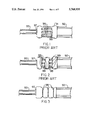
- FIG. 2 is a side view showing a bubble crimp of known prior art.
- FIG. 4 is a perspective view of the invention.
- FIG. 5 is a top view of the invention in position to crimp a sleeve ferrule onto a hose as powered by a drive means.
- FIG. 6 is a side view of a crimping blade as removed from the base member.
- FIG. 9 is a side view of an opposing pair of crimping blades in the full crimp position.
- the invention is in general a device for permanently attaching a hose made of compressible rubber, polymer or other similar material to a metal tube or the like by deformably crimping a sleeve ferrule or similarly configured fitting disposed externally to the hose, which in turn has the stem of the tubing disposed internally within its internal bore, the crimped ferrule compressing the hose material tightly against the tubing stem to preclude separation of the components.
- First crimper assembly 10 comprises a first base member 11, which is shown as a generally rectangular block or housing structured to receive and retain a first set of crimper blades 13.
- First base member 11 can be of various shapes and configurations as long as the set of crimper blades 13 is rigidly secured therein.
- the first set of crimper blades 13 is composed of three individual crimper blades 14, 15 and 16, which are mounted in parallel alignment extending from one side of the first base member 11.
- the second crimper assembly 20 comprises a second base member 21 having a second set of crimper blades 23 composed of three individual crimper blades 24, 25 and 26 mounted in parallel alignment extending from one side of second base member 21.
- the sets of crimper blades 13 and 23 may be mounted or attached to the base members 11 and 21 in any suitable manner, but preferably each individual blade 14-16 and 24-26 is inserted into one of plural slots 12 or 22 cut into the base members 11.
- the main body 51 of each crimper blade 50 as shown in FIG. 6, is provided with one or more mounting apertures 63 which align with mounting apertures 61 cut into base members 11 and 21.
- a mounting pin or rod 62 is inserted through apertures 61 and 63 to secure the crimping blades 50 in place.
- This construction allows individual blades 50 to be removed from the base members 11 or 21 and replaced if necessary.
- the first crimper assembly 10 and second crimper assembly 20 are relatively disposed such that the first set of crimper blades 13 faces the second set of crimper blades 23, preferably by positioning each crimper assembly 10 and 20 on a generally planar support base or plate 95, which may be provided with channels or shoulders to guide the crimper assemblies 10 and 20 during linear movement.
- a detent flange 96 or other stop means is provided to retain the first crimper assembly 10 in a stationary manner as the second crimper assembly 20 is advanced towards it by a drive means 94.
- Drive means 94 may comprise any suitable means to deliver sufficient power to close the two crimper assemblies 10 and 20 about a sleeve ferrule 91/hose 92/tubing stem 93 assembly, such as for example a hydraulic or pneumatic piston, a drive screw, gears, etc.
- Drive means connector means 70 which may comprise an aperture to receive the ram of the hydraulic piston, allows power to be transferred from the drive means 70 to the second crimping assembly 20.
- each crimper blade 50 is shown in FIGS. 6 and 7.
- the crimper blades 50 must be constructed of a hard material, such as steel, which is capable of applying sufficient force to deform a sleeve ferrule 91.
- the crimper blade 50 comprises a main body 51 which is generally rectangular in configuration and relatively thin in cross-section, each blade 50 having an abutting side 73 and a non-abutting side 74.
- the end 59 of the crimper blade 50 not connected to base members 11 or 21 contains a crimping slot 52, generally centrally disposed, which is wide enough to receive the ferrule 91 with some amount of clearance.
- the major portion of the crimping slot 52 consists of an angled portion 56, such that the width of crimping slot 52 diminishes in the direction toward the interior of the main body 51 and base member 11 or 21.
- the crimping slot 52 terminates in a semi-circular portion 54, the radius of this semi-circular portion 54 determining the final external diameter of the crimping recess 98 in the sleeve ferrule 91 after it has been crimped by the device.
- the crimping slot 52 also comprises a first parallel portion 55 positioned between the semi-circular portion 54 and angled portion 56, over which the opposing edges of crimping slot 52 are in parallel alignment and separated by a distance equal to twice the radius of the semi-circular portion 54. Also most preferably, the crimping slot 52 comprises a second parallel portion 57 positioned between the angled portion 56 and the end 59 of crimping blade 50, over which the opposing edges of crimping slot 52 are in parallel alignment. Preferably end 59 is bevelled to the side of crimper blade 50 opposite that of the bevelled shoulder 53.
- the second parallel portion 57, angled portion 56, first parallel portion 55 and semicircular portion 54 which comprise crimping slot 52 all share a common edge 58, which is preferably radiused, on the abutting side 73 of blade 50.
- a bevelled shoulder 53 is preferably angled at about 15 degrees, such that the combination of radiused edge 58 and bevelled shoulder 53 presents a wedge-shaped profile against ferrule 91, as seen in FIG. 8.
- the particular dimensions of crimping slot 52 and crimping blade 50 are dependent on the size of the assembly being crimped, which will usually be one of four standard sizes.
- the crimper blades 50 are mounted in the crimper assemblies 10 and 20 in a particular manner, such that a blade 50 on the first crimper assembly 10 contiguously abuts a particular blade 50 on the second crimper assembly 20 when the two assemblies 10 and 20 are properly aligned and advanced to perform the crimping operation, as shown in FIGS. 5 and 10.
- a first crimper blade 14 of the first set of crimper blades 13 is positioned to abuttingly align with a first crimper blade 24 of the second set of crimper blades 23, a second blade 15 of first set 13 aligns with a second blade 25 of second set 23, and a third blade 16 of first set 13 aligns with a third blade 26 of second set 23.
- the crimping blades 14, 15 and 16 are disposed in base member 11 and the crimping blades 24, 25, and 26 are preferably disposed in base member 21 such that the separation between the conjunctions of blades 14/24 and blades 15/25 is approximately equal to the separation between the conjunction of blades 15/25 and blades 16/26.
- the annular crimping recesses 98 formed in the ferrule 91 will likewise be separated an equal amount.
- the separation distance between blades 14, 15 and 16 is not equal to the separation between blades 24, 25 and 26, since it is preferable that the outermost pair of blades 50 in one crimping assembly, shown in FIG.
- blades 24 and 26 in second crimping assembly 20 be separated a greater distance than the outermost set of blades in the other crimping assembly, shown herein blades 14 and 16 of first crimping assembly 10, such that blades 24 and 26 act to properly align and contain the first crimping assembly 10 and prevent relative movement in the transverse or axial direction.
- the abutting sides 73 of each blade 24 and 26 will face inwardly and the abutting sides 73 of each blade 14 and 16 will face outwardly.
- Each pairing of crimper blades 14/24, 15/25 and 16/26 are assembled such that the abutting side 73 with the radiused edge 58 of each crimping slot 52 in a blade 50 of the first set of crimping blades 13 abuts the abutting side 73 with the radiused edge 58 of each crimping slot 52 in a blade 50 of the second set of crimping blades 23, as seen in FIG. 8.
- the bevelled shoulders 53 will always face outwardly in each blade pairing 14/24, 15/25 and 16/26, such that a tapered wedge-shape is forced against the ferrule 91.
- the bevelled ends 59 of opposing aligned blades 50 will cause the blades 50 to be directed toward the proper side of the pairing whenever the two crimping assemblies 10 and 20 are positioned and advanced, should a slight misalignment occur.
- the distance from the central axis of semi-circular portion 54 to the end 59 of each blade 50 is preferably equal to the distance from the central axis to the base member 11 or 21.
- the ends 59 abut the base members 11 and 21 at the point where the opening formed by the conjunction of the semi-circular portions 54 of each of the contiguous blade pairings 14/24, 15/25 and 16/26 is a perfect circle, thus preventing the assemblies 10 and 20 from advancing beyond the point where the optimum circular crimp is achieved.
- the crimping operation is performed by positioning a hose 92 within a sleeve ferrule 91 mounted, such as by a bead lock 97, onto a stem tubing 93. This assembly is then positioned with the ferrule 91 extending transversely through the crimping slots 52 of the first crimping assembly 10. The second crimping assembly 20 is then aligned and advanced toward the ferrule 91 and first crimping assembly 10 such that the second set of crimper blades 23 abuts in parallel manner the first set of crimper blades 13 with the ferrule 91/hose 92/stem 93 assembly enclosed by each pairing of crimper blades 50, as shown in FIG. 5.
- Power drive means 94 is activated and the second crimper assembly 20 is advanced toward the first crimper assembly 10, which is held in stationary position by detent flange 96 on support base 95.
- the effective opening size of the slots 52 between each blade pairing 14/24, 15/25 and 16/26 decreases as the narrower parts of the angled portions 56 are advanced relative to each other. This movement initiates a crimping action such that three recesses 98 are formed in the ferrule 91, each recess 98 beginning first at two opposing points on the circumference and then advancing around the perimeter.
- the crimping recess 98 deepens.
- each blade pairing 14/24, 15/25 and 16/26 meet such that they share a common central axis, whereby the recesses 98 now formed are annular and circumscribe the ferrule 91 a full 360 degrees, as shown in FIG. 3.
- the sliding motion of the opposing sets of crimper blades 13 and 23 easily deform the metal sleeve ferrule 91, such that the hose 92 is tightly compressed at three positions against the internal stem 93, securely attaching the hose 92 to the stem 93.
- the second crimper assembly 20 is then retracted from the first crimper assembly 10 and the crimped assembly removed for use.
- FIG. 10 shows a crimp being performed to join a hose 92 to a tubing stem 92 which is preformed in close conjunction with a second tubing member 93.
- the crimper device is comprised of two independent crimping assemblies 10 and 20 which can be separated completely and which have crimper blades 50 of relatively small dimensions, the crimper assemblies 10 and 20 can be assembled around the first tubing stem 93, the crimping operation performed and the crimper assemblies 10 and 20 disassembled to remove the crimped hose 92.
- the device only requires minimal clearance in all directions and can be used with a large number of complicated tubing configurations.
- a crimp consists of deeply compressed recesses 98 and elevated crimp shoulders 99.
- the prior art crimping patterns produce raised shoulders 99 extending in the longitudinal direction of the assembly. These raised shoulders 99 provide a potential leak pathway, since the hose 92 is not fully compressed in these regions.
- the totally annular crimp recesses 99 produced by the invention, as seen in FIG. 3, do not have any longitudinal crimp shoulders, thereby providing an improved configuration to prevent fluid loss.
Landscapes
- Engineering & Computer Science (AREA)
- Mechanical Engineering (AREA)
- Joints That Cut Off Fluids, And Hose Joints (AREA)
Abstract
Description
Claims (10)
Priority Applications (1)
| Application Number | Priority Date | Filing Date | Title |
|---|---|---|---|
| US08/816,858 US5768935A (en) | 1997-03-13 | 1997-03-13 | Blade crimping device |
Applications Claiming Priority (1)
| Application Number | Priority Date | Filing Date | Title |
|---|---|---|---|
| US08/816,858 US5768935A (en) | 1997-03-13 | 1997-03-13 | Blade crimping device |
Publications (1)
| Publication Number | Publication Date |
|---|---|
| US5768935A true US5768935A (en) | 1998-06-23 |
Family
ID=25221795
Family Applications (1)
| Application Number | Title | Priority Date | Filing Date |
|---|---|---|---|
| US08/816,858 Expired - Lifetime US5768935A (en) | 1997-03-13 | 1997-03-13 | Blade crimping device |
Country Status (1)
| Country | Link |
|---|---|
| US (1) | US5768935A (en) |
Cited By (8)
| Publication number | Priority date | Publication date | Assignee | Title |
|---|---|---|---|---|
| US6481262B2 (en) * | 1999-12-30 | 2002-11-19 | Advanced Cardiovascular Systems, Inc. | Stent crimping tool |
| US6484553B1 (en) * | 2001-05-01 | 2002-11-26 | Delphi Technologies, Inc. | Swage dies for swage-ring clamps |
| US6779575B1 (en) * | 1998-05-28 | 2004-08-24 | Novaseptum Ab | Sealing appliance |
| US20050234537A1 (en) * | 2004-04-16 | 2005-10-20 | Scimed Life Systems, Inc. | Stent crimper |
| US20090054873A1 (en) * | 2002-01-31 | 2009-02-26 | Baxter International Inc. | Apparatus and method for connecting and disconnecting flexible tubing |
| US20090072532A1 (en) * | 2005-08-16 | 2009-03-19 | Keith Dixon-Roche | Terminations for high-pressure/high-temperature hoses |
| US20140352130A1 (en) * | 2013-05-31 | 2014-12-04 | Custom Machining Services, Inc. | Crimping machine and methods of making and using |
| US11560971B2 (en) * | 2017-04-14 | 2023-01-24 | John A. Morin | Methods and apparatus for using crimp rings on flexible tubing |
Citations (6)
| Publication number | Priority date | Publication date | Assignee | Title |
|---|---|---|---|---|
| US810241A (en) * | 1904-09-10 | 1906-01-16 | Shelby Steel Tube Company | Apparatus for reducing the ends of tubes. |
| US2009829A (en) * | 1933-05-13 | 1935-07-30 | Schraders Son Inc | Ferrule contracting tool |
| US2832244A (en) * | 1953-10-14 | 1958-04-29 | Edgar W Olson | Wire straightening pliers |
| US3919877A (en) * | 1973-11-06 | 1975-11-18 | Thomas & Betts Corp | Tool |
| US4337635A (en) * | 1980-07-03 | 1982-07-06 | Teledyne Penn-Union | Compression tool |
| US5263355A (en) * | 1991-03-28 | 1993-11-23 | Establissements Pierre Grehal Et Cie | Necking pliers for pipes and the like |
-
1997
- 1997-03-13 US US08/816,858 patent/US5768935A/en not_active Expired - Lifetime
Patent Citations (6)
| Publication number | Priority date | Publication date | Assignee | Title |
|---|---|---|---|---|
| US810241A (en) * | 1904-09-10 | 1906-01-16 | Shelby Steel Tube Company | Apparatus for reducing the ends of tubes. |
| US2009829A (en) * | 1933-05-13 | 1935-07-30 | Schraders Son Inc | Ferrule contracting tool |
| US2832244A (en) * | 1953-10-14 | 1958-04-29 | Edgar W Olson | Wire straightening pliers |
| US3919877A (en) * | 1973-11-06 | 1975-11-18 | Thomas & Betts Corp | Tool |
| US4337635A (en) * | 1980-07-03 | 1982-07-06 | Teledyne Penn-Union | Compression tool |
| US5263355A (en) * | 1991-03-28 | 1993-11-23 | Establissements Pierre Grehal Et Cie | Necking pliers for pipes and the like |
Cited By (17)
| Publication number | Priority date | Publication date | Assignee | Title |
|---|---|---|---|---|
| USRE45938E1 (en) * | 1998-05-28 | 2016-03-22 | Merck Chemicals And Life Science Ab | Sealing appliance |
| US6779575B1 (en) * | 1998-05-28 | 2004-08-24 | Novaseptum Ab | Sealing appliance |
| USRE46544E1 (en) * | 1998-05-28 | 2017-09-12 | Merck Chemicals And Life Science Ab | Sealing appliance |
| USRE46183E1 (en) * | 1998-05-28 | 2016-10-25 | Merck Chemicals And Life Science Ab | Sealing appliance |
| US20090250157A1 (en) * | 1998-05-28 | 2009-10-08 | Nils Arthun | Sealing appliance |
| USRE41169E1 (en) | 1998-05-28 | 2010-03-30 | Millipore Ab | Sealing appliance |
| US7959754B2 (en) | 1998-05-28 | 2011-06-14 | Millipore Ab | Sealing appliance |
| US20110197426A1 (en) * | 1998-05-28 | 2011-08-18 | Millipore Ab | Sealing Appliance |
| US6481262B2 (en) * | 1999-12-30 | 2002-11-19 | Advanced Cardiovascular Systems, Inc. | Stent crimping tool |
| US6484553B1 (en) * | 2001-05-01 | 2002-11-26 | Delphi Technologies, Inc. | Swage dies for swage-ring clamps |
| US20090054873A1 (en) * | 2002-01-31 | 2009-02-26 | Baxter International Inc. | Apparatus and method for connecting and disconnecting flexible tubing |
| US8146642B2 (en) * | 2002-01-31 | 2012-04-03 | Baxter International Inc. | Apparatus and method for connecting and disconnecting flexible tubing |
| US7143625B2 (en) * | 2004-04-16 | 2006-12-05 | Boston Scientific Scimed, Inc. | Stent crimper |
| US20050234537A1 (en) * | 2004-04-16 | 2005-10-20 | Scimed Life Systems, Inc. | Stent crimper |
| US20090072532A1 (en) * | 2005-08-16 | 2009-03-19 | Keith Dixon-Roche | Terminations for high-pressure/high-temperature hoses |
| US20140352130A1 (en) * | 2013-05-31 | 2014-12-04 | Custom Machining Services, Inc. | Crimping machine and methods of making and using |
| US11560971B2 (en) * | 2017-04-14 | 2023-01-24 | John A. Morin | Methods and apparatus for using crimp rings on flexible tubing |
Similar Documents
| Publication | Publication Date | Title |
|---|---|---|
| US4186946A (en) | Rotatable hose or tube coupling | |
| US6227030B1 (en) | Electrical connector crimping die with over-crimp prevention surface and method | |
| KR100639850B1 (en) | Fitting or mounting for producing a press joint with an inserted tube end | |
| US4328983A (en) | Positive seal steel coupling apparatus and method therefor | |
| US6193195B1 (en) | Clamp for metal tubing | |
| US4412693A (en) | Swivel hose coupling with threaded nipple | |
| KR840001158B1 (en) | Fluid fitting | |
| US2850303A (en) | Double sealed compression fitting | |
| KR20000029601A (en) | Pipe joint | |
| US5029907A (en) | Band for effecting a seal | |
| US5768935A (en) | Blade crimping device | |
| US20070096461A1 (en) | Crimped hose fitting | |
| KR100545910B1 (en) | Pipe Coupling | |
| KR100697790B1 (en) | Hydraulic hose fitting and method | |
| US5615481A (en) | Method and apparatus for the production of circumferentially compressible pipe fittings | |
| US20070236017A1 (en) | Fitting | |
| EP0381709B1 (en) | Compact fluid operated apparatus and method | |
| US3744122A (en) | Method of forming staked seal for tubular parts | |
| US3803897A (en) | Compression staking apparatus | |
| EP3388164B1 (en) | Method and apparatus for using crimp rings on flexible tubing | |
| US20100148495A1 (en) | Device, method and kit of parts for forming a press-fit connection with a tube | |
| KR100394852B1 (en) | Jointing structure of press type pipe joint | |
| EP2065978A1 (en) | A mechanical connector with incorporated cable centring means | |
| US7383714B2 (en) | Crimp machine with quick release pushers | |
| US4765659A (en) | High pressure tube attachment mechanism |
Legal Events
| Date | Code | Title | Description |
|---|---|---|---|
| STCF | Information on status: patent grant |
Free format text: PATENTED CASE |
|
| REMI | Maintenance fee reminder mailed | ||
| FPAY | Fee payment |
Year of fee payment: 4 |
|
| SULP | Surcharge for late payment | ||
| REMI | Maintenance fee reminder mailed | ||
| FPAY | Fee payment |
Year of fee payment: 8 |
|
| SULP | Surcharge for late payment |
Year of fee payment: 7 |
|
| AS | Assignment |
Owner name: OWENS, CARL H, JR, FLORIDA Free format text: ASSIGNMENT OF ASSIGNORS INTEREST;ASSIGNOR:OWENS, CARL H;REEL/FRAME:022892/0769 Effective date: 20071010 |
|
| FPAY | Fee payment |
Year of fee payment: 12 |
|
| AS | Assignment |
Owner name: STARK MANUFACTURING, LLC, NEW YORK Free format text: ASSIGNMENT OF ASSIGNORS INTEREST;ASSIGNOR:OWENS, CARL H. JR.;REEL/FRAME:023758/0480 Effective date: 20091007 |