US5769499A - Motor vehicle seat - Google Patents
Motor vehicle seat Download PDFInfo
- Publication number
- US5769499A US5769499A US08/660,523 US66052396A US5769499A US 5769499 A US5769499 A US 5769499A US 66052396 A US66052396 A US 66052396A US 5769499 A US5769499 A US 5769499A
- Authority
- US
- United States
- Prior art keywords
- seat back
- back frame
- opposing ends
- pair
- guide tubes
- Prior art date
- Legal status (The legal status is an assumption and is not a legal conclusion. Google has not performed a legal analysis and makes no representation as to the accuracy of the status listed.)
- Expired - Lifetime
Links
Images


Classifications
-
- B—PERFORMING OPERATIONS; TRANSPORTING
- B60—VEHICLES IN GENERAL
- B60N—SEATS SPECIALLY ADAPTED FOR VEHICLES; VEHICLE PASSENGER ACCOMMODATION NOT OTHERWISE PROVIDED FOR
- B60N2/00—Seats specially adapted for vehicles; Arrangement or mounting of seats in vehicles
- B60N2/68—Seat frames
- B60N2/682—Joining means
-
- B—PERFORMING OPERATIONS; TRANSPORTING
- B60—VEHICLES IN GENERAL
- B60N—SEATS SPECIALLY ADAPTED FOR VEHICLES; VEHICLE PASSENGER ACCOMMODATION NOT OTHERWISE PROVIDED FOR
- B60N2/00—Seats specially adapted for vehicles; Arrangement or mounting of seats in vehicles
- B60N2/80—Head-rests
- B60N2/806—Head-rests movable or adjustable
- B60N2/809—Head-rests movable or adjustable vertically slidable
-
- Y—GENERAL TAGGING OF NEW TECHNOLOGICAL DEVELOPMENTS; GENERAL TAGGING OF CROSS-SECTIONAL TECHNOLOGIES SPANNING OVER SEVERAL SECTIONS OF THE IPC; TECHNICAL SUBJECTS COVERED BY FORMER USPC CROSS-REFERENCE ART COLLECTIONS [XRACs] AND DIGESTS
- Y10—TECHNICAL SUBJECTS COVERED BY FORMER USPC
- Y10T—TECHNICAL SUBJECTS COVERED BY FORMER US CLASSIFICATION
- Y10T29/00—Metal working
- Y10T29/49—Method of mechanical manufacture
- Y10T29/49616—Structural member making
- Y10T29/49622—Vehicular structural member making
-
- Y—GENERAL TAGGING OF NEW TECHNOLOGICAL DEVELOPMENTS; GENERAL TAGGING OF CROSS-SECTIONAL TECHNOLOGIES SPANNING OVER SEVERAL SECTIONS OF THE IPC; TECHNICAL SUBJECTS COVERED BY FORMER USPC CROSS-REFERENCE ART COLLECTIONS [XRACs] AND DIGESTS
- Y10—TECHNICAL SUBJECTS COVERED BY FORMER USPC
- Y10T—TECHNICAL SUBJECTS COVERED BY FORMER US CLASSIFICATION
- Y10T29/00—Metal working
- Y10T29/49—Method of mechanical manufacture
- Y10T29/49789—Obtaining plural product pieces from unitary workpiece
- Y10T29/49798—Dividing sequentially from leading end, e.g., by cutting or breaking
-
- Y—GENERAL TAGGING OF NEW TECHNOLOGICAL DEVELOPMENTS; GENERAL TAGGING OF CROSS-SECTIONAL TECHNOLOGIES SPANNING OVER SEVERAL SECTIONS OF THE IPC; TECHNICAL SUBJECTS COVERED BY FORMER USPC CROSS-REFERENCE ART COLLECTIONS [XRACs] AND DIGESTS
- Y10—TECHNICAL SUBJECTS COVERED BY FORMER USPC
- Y10T—TECHNICAL SUBJECTS COVERED BY FORMER US CLASSIFICATION
- Y10T29/00—Metal working
- Y10T29/49—Method of mechanical manufacture
- Y10T29/49826—Assembling or joining
- Y10T29/49908—Joining by deforming
- Y10T29/49915—Overedge assembling of seated part
-
- Y—GENERAL TAGGING OF NEW TECHNOLOGICAL DEVELOPMENTS; GENERAL TAGGING OF CROSS-SECTIONAL TECHNOLOGIES SPANNING OVER SEVERAL SECTIONS OF THE IPC; TECHNICAL SUBJECTS COVERED BY FORMER USPC CROSS-REFERENCE ART COLLECTIONS [XRACs] AND DIGESTS
- Y10—TECHNICAL SUBJECTS COVERED BY FORMER USPC
- Y10T—TECHNICAL SUBJECTS COVERED BY FORMER US CLASSIFICATION
- Y10T29/00—Metal working
- Y10T29/49—Method of mechanical manufacture
- Y10T29/49826—Assembling or joining
- Y10T29/49908—Joining by deforming
- Y10T29/49925—Inward deformation of aperture or hollow body wall
- Y10T29/49927—Hollow body is axially joined cup or tube
-
- Y—GENERAL TAGGING OF NEW TECHNOLOGICAL DEVELOPMENTS; GENERAL TAGGING OF CROSS-SECTIONAL TECHNOLOGIES SPANNING OVER SEVERAL SECTIONS OF THE IPC; TECHNICAL SUBJECTS COVERED BY FORMER USPC CROSS-REFERENCE ART COLLECTIONS [XRACs] AND DIGESTS
- Y10—TECHNICAL SUBJECTS COVERED BY FORMER USPC
- Y10T—TECHNICAL SUBJECTS COVERED BY FORMER US CLASSIFICATION
- Y10T29/00—Metal working
- Y10T29/49—Method of mechanical manufacture
- Y10T29/49826—Assembling or joining
- Y10T29/49908—Joining by deforming
- Y10T29/49938—Radially expanding part in cavity, aperture, or hollow body
- Y10T29/4994—Radially expanding internal tube
-
- Y—GENERAL TAGGING OF NEW TECHNOLOGICAL DEVELOPMENTS; GENERAL TAGGING OF CROSS-SECTIONAL TECHNOLOGIES SPANNING OVER SEVERAL SECTIONS OF THE IPC; TECHNICAL SUBJECTS COVERED BY FORMER USPC CROSS-REFERENCE ART COLLECTIONS [XRACs] AND DIGESTS
- Y10—TECHNICAL SUBJECTS COVERED BY FORMER USPC
- Y10T—TECHNICAL SUBJECTS COVERED BY FORMER US CLASSIFICATION
- Y10T29/00—Metal working
- Y10T29/53—Means to assemble or disassemble
- Y10T29/53996—Means to assemble or disassemble by deforming
Definitions
- the present invention relates generally to motor vehicle seats, and more particularly to a seat back frame.
- vehicle seat assemblies include a recliner mechanism which supports a substantially U-shaped seat back frame with a cross-member extending across the back frame, and head rest guide tubes extending through the back frame for supporting a head rest assembly.
- an aluminum back frame comprises a hollow aluminum tube bent into a U-shaped configuration. The tube is usually bent in an unheat-treated condition, and then heat-treated after bending, or alternatively, the tube is annealed locally for bending. The heat-treating operation adds substantial manufacturing, handling, and shipping costs to the assembly.
- the prior art bent tubes are deformed in the upper bending corners and have thin walls in the attachment areas, which results in a high shear stress.
- the thin attachment areas require a splint or insert to be inserted therein to reduce the shear stress.
- apertures must be bored through both sides of the back frame tube, which may be awkward and may unnecessarily increase manufacturing costs.
- the present invention overcomes the above-referenced shortcomings of prior art seat assemblies by providing a seat back frame in the form of an extruded solid aluminum I-beam which does not require heat treatment for bending, localized heat treatment prior to bending, or post-bending heat treatment.
- the present invention provides an apparatus for supporting a seat back in a vehicle, comprising an aluminum I-beam formed in a generally U-shaped configuration, and having opposing ends supported with respect to the vehicle.
- the I-beam forms a seat back frame for supporting a seat back.
- the present invention further provides a method of manufacturing a vehicle seat back frame, comprising the following steps: a) extruding an aluminum I-beam comprising a center support positioned between first and second flanges extending the length of the I-beam; b) cutting the I-beam to a desired length; c) age-hardening the I-beam; and d) bending the I-beam into a substantially U-shaped configuration, such that the center support and first and second flanges cooperate to form an inwardly-facing channel and an outwardly-facing channel.
- the assembly includes a cross-member extending across the U-shaped I-beam, with the cross-member attached to the I-beam at opposing ends by a pair of swaged nuts.
- the present invention also provides a method for attaching a head rest guide tube to a seat back frame having a substantially flat section with an aperture formed therethrough.
- the method comprises inserting the guide tube into the aperture and swaging (also termed “swedging") the guide tube on both sides of the flat section whereby to secure the guide tube within the aperture.
- an object of the present invention is to provide an aluminum seat back frame which does not require specialized heat treatment for bending.
- Another object of the present invention is to provide a vehicle seat back frame with improved structural integrity.
- Yet another object of the present invention is to provide a vehicle seat back frame with reduced manufacturing costs.
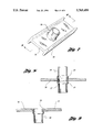
- FIG. 1 shows an exploded perspective view of a vehicle seat assembly in accordance with the present invention
- FIG. 2 shows a perspective end view of a seat back frame assembly in accordance with the present invention
- FIG. 3 shows a side perspective view of the seat back frame assembly shown in FIG. 2;
- FIG. 4 shows a partial perspective view of a seat back frame and head rest assembly in accordance with the present invention
- FIG. 5 shows a perspective view of a seat back frame with a swage-bolted cross-member in accordance with the present invention
- FIG. 6 schematically illustrates method steps for manufacturing a vehicle seat back frame in accordance with the present invention
- FIG. 7 shows a cutaway perspective view of a seat back frame with a head rest guide tube secured thereto;
- FIG. 8 shows a cross-sectional view of the seat back frame and head rest guide tube shown in FIG. 7;
- FIG. 9 shows a vertical cross-sectional view of a lower a attachment bolt secured to the back frame.
- FIG. 1 shows an exploded perspective view of a vehicle seat assembly 10 in accordance with the present invention.
- the assembly 10 includes a cushion frame 12 supported by a pair of support brackets 14,16.
- the support brackets 14,16 are mounted by the seat adjusters 18,20, which mount the assembly in the vehicle.
- the seat back frame 22 is pivotally mounted with respect to the cushion frame 12 by means of the recliner mechanism 24,26.
- the seat back frame 22 includes a lumbar support structure 28 mounted thereto, as well as a head rest support assembly 30 for supporting a head rest cushion with respect to the seat back frame 22.
- the seat back frame 22 is more clearly shown in FIGS. 2 and 3.
- the seat back frame 22 comprises an aluminum I-beam 32 bent in a substantially U-shaped configuration.
- the I-beam 32 includes opposing ends 34,36 which are pivotally supported with respect to the vehicle by the recliner mechanisms 24,26.
- the I-beam 32 includes a center support 38 positioned between first and second flanges 40,42 extending the length of the I-beam 32.
- the center support 38 and first and second flanges 40,42 are more clearly shown in FIG. 5.
- the I-beam 32 forms an outwardly-facing channel 44, and an inwardly-facing channel 46.
- the seat back frame 22 includes a cross-member 48 extending between the opposing ends 34,36 of the I-beam 32.
- the cross-member 48 is secured to the center support portion 38 of the I-beam 32 by the nuts 50.
- the bolts 50 include a flange 52 which is swaged against the dowel portion 54 of the cross-member 48 for securing the cross-member 48 with respect to the I-beam 32. In this manner, a welding operation is eliminated from the seat back frame assembly process.
- the center support portion 38 includes a countersink 39 on the outer surface 41 so that the nut 50 may be secured flush with the outer surface 41.
- the head rest support assembly 30 includes a pair of head rest guide tubes 56,58 which are welded into position within a pair of apertures formed in the center support section 38 of the I-beam 32. Alternatively, the head rest guide tubes 56,58 could be swaged into position for support with respect to the I-beam 32 (as discussed below with reference to FIGS. 7 and 8).
- Plastic head rest adjustment mechanisms 60,62 are supported within the guide tubes 56,58.
- a head rest support bar 64 is adjustably supported within the plastic adjustment mechanisms 60,62 for vertical adjustment of the head rest.
- the present invention also provides a method of manufacturing a seat back frame, as illustrated in FIG. 6.
- the method includes extruding an aluminum I-beam (step 70); cutting the I-beam to a desired length (step 72); age-hardening the I-beam (step 74); roll-bending the I-beam in a bend fixture (step 76); boring attachment apertures in the I-beam (step 78); and boring head rest guide tube apertures in the I-beam (step 80).
- the method further comprises welding guide tubes in the guide tube apertures (step 82), or swaging guide tubes in the guide tube apertures (step 82'); and swage-bolting a cross-member between opposing ends of the I-beam (step 84).
- the aluminum I-beam may be purchased in a T6 (fully age-hardened) condition, rather than purchasing in a lower T4 condition, which would require post-bending of the I-beam and then shipping the I-beam back to an appropriate facility for age-hardening to the T-6 condition.
- Elimination of the step of locally annealing the back frame for bending, or bending the back frame in an unheat-treated condition, and then heat-treating after the bending operation, will significantly reduce manufacturing costs.
- FIGS. 7 and 8 illustrate a double-swaging attachment of the guide tube 56 to the flat portion (center support) 38 of the I-beam 32.
- the guide tube 56 is inserted into an aperture 57 formed in the substantially flat center support 38, and is swaged on both sides of the flat section 38 whereby to secure the guide tube 56 within the aperture 57.
- the swaged portions 59,61 abut the flat center support 38 for securing the guide tube 56.
- the guide tube 56 has one swaged portion 59 pre-formed, then it is inserted into the aperture 57, and the second swaged portion 61 is formed after insertion.
- This configuration eliminates welding of the guide tubes, which would require aluminum guide tubes to cooperate with the aluminum back frame. By swaging rather than welding, a steel or other available headrest guide tube could be used.
Abstract
Description
σ=MY/I
Claims (6)
Priority Applications (5)
| Application Number | Priority Date | Filing Date | Title |
|---|---|---|---|
| US08/660,523 US5769499A (en) | 1996-06-07 | 1996-06-07 | Motor vehicle seat |
| PCT/US1997/009997 WO1997046413A1 (en) | 1996-06-07 | 1997-06-09 | Motor vehicle seat |
| US09/014,875 US6223436B1 (en) | 1996-06-07 | 1998-01-28 | Motor vehicle seat |
| US09/820,147 US6836951B2 (en) | 1996-06-07 | 2001-03-28 | Attachment of head rest guide tube to vehicle seat frame |
| US10/904,938 US7213887B2 (en) | 1996-06-07 | 2004-12-06 | Attachment of head rest guide tube to vehicle seat frame |
Applications Claiming Priority (1)
| Application Number | Priority Date | Filing Date | Title |
|---|---|---|---|
| US08/660,523 US5769499A (en) | 1996-06-07 | 1996-06-07 | Motor vehicle seat |
Related Child Applications (1)
| Application Number | Title | Priority Date | Filing Date |
|---|---|---|---|
| US09/014,875 Division US6223436B1 (en) | 1996-06-07 | 1998-01-28 | Motor vehicle seat |
Publications (1)
| Publication Number | Publication Date |
|---|---|
| US5769499A true US5769499A (en) | 1998-06-23 |
Family
ID=24649872
Family Applications (4)
| Application Number | Title | Priority Date | Filing Date |
|---|---|---|---|
| US08/660,523 Expired - Lifetime US5769499A (en) | 1996-06-07 | 1996-06-07 | Motor vehicle seat |
| US09/014,875 Expired - Lifetime US6223436B1 (en) | 1996-06-07 | 1998-01-28 | Motor vehicle seat |
| US09/820,147 Expired - Fee Related US6836951B2 (en) | 1996-06-07 | 2001-03-28 | Attachment of head rest guide tube to vehicle seat frame |
| US10/904,938 Expired - Fee Related US7213887B2 (en) | 1996-06-07 | 2004-12-06 | Attachment of head rest guide tube to vehicle seat frame |
Family Applications After (3)
| Application Number | Title | Priority Date | Filing Date |
|---|---|---|---|
| US09/014,875 Expired - Lifetime US6223436B1 (en) | 1996-06-07 | 1998-01-28 | Motor vehicle seat |
| US09/820,147 Expired - Fee Related US6836951B2 (en) | 1996-06-07 | 2001-03-28 | Attachment of head rest guide tube to vehicle seat frame |
| US10/904,938 Expired - Fee Related US7213887B2 (en) | 1996-06-07 | 2004-12-06 | Attachment of head rest guide tube to vehicle seat frame |
Country Status (2)
| Country | Link |
|---|---|
| US (4) | US5769499A (en) |
| WO (1) | WO1997046413A1 (en) |
Cited By (33)
| Publication number | Priority date | Publication date | Assignee | Title |
|---|---|---|---|---|
| US5967612A (en) * | 1998-06-18 | 1999-10-19 | Tachi-S Co., Ltd. | Headrest for automotive seat |
| US6019273A (en) * | 1995-09-08 | 2000-02-01 | Euromotive Ges.M.B.H. | Process for manufacturing the frame of a back rest of a vehicle |
| US6027167A (en) * | 1996-02-29 | 2000-02-22 | Blomdell; Peter | Method to safely restrain occupants in a crashing vehicle and a seat constructed to perform said method |
| US6035516A (en) * | 1997-04-25 | 2000-03-14 | Bend All Manufacturing Inc. | Securement of head rest support into automobile seat frame |
| US6056366A (en) * | 1999-02-26 | 2000-05-02 | Lear Corporation | Composite back frame for a vehicle seat and method for distributing seat belt loads |
| US6223436B1 (en) * | 1996-06-07 | 2001-05-01 | Lear Corporation | Motor vehicle seat |
| US6224158B1 (en) | 1999-11-08 | 2001-05-01 | Illinois Tool Works Inc. | Headrest assembly |
| US6241318B1 (en) * | 1999-05-31 | 2001-06-05 | Ikeda Bussan Co., Ltd. | Seat-back frame |
| US6296316B1 (en) | 1999-12-01 | 2001-10-02 | Illinois Tool Works Inc. | Adjustable headrest guide |
| US6361239B1 (en) * | 1999-12-10 | 2002-03-26 | Lear Corporation | Bolt with expandable bushing for pivot attachment |
| EP1057690A3 (en) * | 1999-05-31 | 2002-04-17 | Ikeda Bussan Co., Ltd. | Seat back frame for automotive vehicles |
| DE10048128A1 (en) * | 2000-09-28 | 2002-04-25 | Keiper Gmbh & Co | Side spar for vehicle seat structure has sections forming a roughly symmetrical I-profile transverse to longitudinal direction of spar |
| US6398300B1 (en) * | 1997-08-26 | 2002-06-04 | Henderson's Industries Pty. Ltd. | Seat backrest mounting |
| US6662422B2 (en) | 2001-08-13 | 2003-12-16 | Camaco | Method for attaching a headrest guide to a seat frame |
| US6709061B2 (en) | 2002-02-06 | 2004-03-23 | Triton Tubular Components Corp. | Seat frame structure and method for forming |
| US20040135411A1 (en) * | 2003-01-15 | 2004-07-15 | Hensley Leonard K | Hydro-formed seat adjuster system |
| US6823575B2 (en) * | 1997-04-25 | 2004-11-30 | Bend All Automotive Incorporated | Securement of head rest support into automobile seat frame |
| US20050039714A1 (en) * | 2003-08-22 | 2005-02-24 | Santi John D. | Valve-operating lever |
| US20060290180A1 (en) * | 2005-06-22 | 2006-12-28 | Multina Inc. | Modular seat assembly and method of installation thereof |
| US7216937B2 (en) * | 2002-08-02 | 2007-05-15 | Bend All Automotive Incorporated | Press-formed keyway for headrest mounting tube |
| US20080309144A1 (en) * | 2007-06-14 | 2008-12-18 | Tachi-S Co., Ltd. | Frame assembly of automotive seat |
| CN100522692C (en) * | 2005-04-26 | 2009-08-05 | 株式会社荒井制作所 | Method for manufacturing headrest stay |
| CN101811453A (en) * | 2009-02-20 | 2010-08-25 | 佛吉亚汽车座椅公司 | Vehicle seat, manufacturing process for such a vehicle seat, and machine for implementing the manufacturing process |
| US20110030439A1 (en) * | 2009-04-14 | 2011-02-10 | Gm Global Technology Operations, Inc. | Method for producing a support structure, preferably a support structure for a vehicle seat |
| US20110133538A1 (en) * | 2008-08-29 | 2011-06-09 | Lear Corporation | Vehicle Seat Frame and Method of Making |
| US20150239369A1 (en) * | 2012-09-03 | 2015-08-27 | Ts Tech Co., Ltd. | Seat frame for vehicle seat |
| US20150321239A1 (en) * | 2012-06-21 | 2015-11-12 | Johnson Controls Gmbh | Method for connecting two components |
| US20160166064A1 (en) * | 2013-07-19 | 2016-06-16 | Toyota Jidosha Kabushiki Kaisha | Headrest support structure |
| JP2017081526A (en) * | 2016-04-27 | 2017-05-18 | 株式会社ホンダアクセス | Vehicular seat frame |
| JP2019059366A (en) * | 2017-09-27 | 2019-04-18 | トヨタ紡織株式会社 | Seat back frame |
| US10442327B2 (en) | 2016-12-23 | 2019-10-15 | Ford Global Technologies, Llc | Seat bottom tension member |
| JP2019209816A (en) * | 2018-06-04 | 2019-12-12 | トヨタ紡織株式会社 | Vehicle seat |
| US10562417B2 (en) | 2017-03-28 | 2020-02-18 | Ford Global Technologies, Llc | Reclining seat assembly having tension reacting member |
Families Citing this family (25)
| Publication number | Priority date | Publication date | Assignee | Title |
|---|---|---|---|---|
| FR2772317A1 (en) * | 1997-12-17 | 1999-06-18 | Faure Bertrand Equipements Sa | Vehicle seat with height adjustment mechanism |
| DE19826732B4 (en) * | 1998-06-16 | 2007-03-29 | Euromotive Ges.M.B.H. | Seatback design |
| JP2001149176A (en) * | 1999-11-29 | 2001-06-05 | Tachi S Co Ltd | Seat back frame structure |
| CA2377160A1 (en) * | 2002-03-18 | 2003-09-18 | Andy Skrepnek | Method and apparatus for interlocking tubular members |
| US7062834B2 (en) * | 2003-01-08 | 2006-06-20 | Parker-Hannifin | Process of forming two beads |
| US8091237B2 (en) * | 2004-08-03 | 2012-01-10 | Lear Corporation | Method for making a vehicle seat crossmember |
| DE102005009128B3 (en) * | 2005-03-01 | 2006-06-22 | Keiper Gmbh & Co.Kg | Method for assembly of crash activated headrest in vehicle seating involves headrest which is assembled to vehicle seating along with rear and front bearing shell which are equipped with sub-assembly |
| US7322646B2 (en) * | 2005-11-02 | 2008-01-29 | Lear Corporation | Folding head restraint mechanism |
| CN101500845B (en) | 2006-06-02 | 2012-12-12 | 约翰逊控制技术公司 | Vehicle seat frame and method thereof |
| US20090051165A1 (en) * | 2007-08-22 | 2009-02-26 | Timothy Lee Frost | Orifice Holder Construction |
| JP2009189486A (en) * | 2008-02-13 | 2009-08-27 | Tachi S Co Ltd | Headrest for vehicle seat |
| US20090211496A1 (en) * | 2008-02-19 | 2009-08-27 | Ray Charles Davis | Portable entertainment system |
| US8479663B2 (en) * | 2008-02-19 | 2013-07-09 | Ray Charles Davis | Portable entertainment system |
| US8172326B2 (en) * | 2008-03-14 | 2012-05-08 | Lear Corporation | Pivot joint assembly for a vehicle seat |
| MX2010013185A (en) * | 2008-06-03 | 2011-01-21 | Johnson Controls Tech Co | Seat frame - tailored tubes. |
| US7661758B1 (en) | 2008-10-01 | 2010-02-16 | Lear Corporation | Head restraint support component for a vehicle seat |
| JP5719774B2 (en) * | 2008-10-16 | 2015-05-20 | ジョンソン コントロールズ テクノロジー カンパニーJohnson Controls Technology Company | One part seat structure and cold forming process to create seat structure |
| DE102009003940A1 (en) * | 2008-10-27 | 2010-04-29 | GM Global Technology Operations, Inc., Detroit | Supporting structure for backrest of motor vehicle seat, has strut retainer attached with support points for supporting support struts at cross strut such that support points are upwardly or downwardly displaced with respect to cross strut |
| DE102009017374A1 (en) * | 2009-04-14 | 2010-10-21 | GM Global Technology Operations, Inc., Detroit | Method for producing a structural component for a motor vehicle |
| US9205482B2 (en) * | 2014-03-21 | 2015-12-08 | Alex Global Technology, Inc. | Method for manufacturing integrated aluminum alloy bicycle front fork |
| CN104228638B (en) * | 2014-09-29 | 2016-08-31 | 长城汽车股份有限公司 | A kind of automotive seat and use the automobile of this seat |
| DE102014226276A1 (en) * | 2014-12-17 | 2016-06-23 | Sitech Sitztechnik Gmbh | Backrest of a vehicle seat with a headrest |
| USD809994S1 (en) * | 2016-08-15 | 2018-02-13 | Henry Alexander Braddock, III | Square tube |
| US10800296B2 (en) | 2016-08-29 | 2020-10-13 | Fisher & Company, Incorporated | Seat recliner assembly with hollow cross member |
| US11142103B2 (en) | 2019-01-17 | 2021-10-12 | Fisher & Company, Incorporated | Cross member for seat recliner assembly |
Citations (14)
| Publication number | Priority date | Publication date | Assignee | Title |
|---|---|---|---|---|
| US2458095A (en) * | 1941-10-07 | 1949-01-04 | Lyon Metal Products Inc | Seat construction for chairs |
| US3345730A (en) * | 1963-10-16 | 1967-10-10 | Murray Mfg Corp | Apparatus for affixing a flange to a tube |
| US3895939A (en) * | 1973-10-31 | 1975-07-22 | Us Energy | Weldable, age hardenable, austenitic stainless steel |
| US4522443A (en) * | 1983-08-11 | 1985-06-11 | Blankenburg Karl | Picnic table |
| US4544204A (en) * | 1981-11-11 | 1985-10-01 | Keiper Automobiltechnik Gmbh & Co. Kg | Back frame for seat, particularly for power vehicle seat |
| EP0233822A2 (en) * | 1986-02-21 | 1987-08-26 | Regie Nationale Des Usines Renault | Assembled seat frame with construction modules |
| US4844545A (en) * | 1987-05-11 | 1989-07-04 | Aisin Seiki Kabushiki Kaisha | Headrest apparatus |
| US4923250A (en) * | 1987-02-28 | 1990-05-08 | Aisin Seiki Kabushiki Kaisha | Headrest apparatus |
| US4976493A (en) * | 1989-02-27 | 1990-12-11 | Frankila John W | Vehicle headrest post guide |
| JPH04303032A (en) * | 1991-03-29 | 1992-10-27 | Aisin Seiki Co Ltd | Seat frame device |
| US5393488A (en) * | 1993-08-06 | 1995-02-28 | General Electric Company | High strength, high fatigue structural steel |
| US5401072A (en) * | 1992-10-05 | 1995-03-28 | Starcraft Automotive Corporation | Tethered seat back for preventing rearward movement of a seat back during a vehicle rear-end collision |
| US5522640A (en) * | 1994-12-02 | 1996-06-04 | Weber Aircraft, Inc. | Apparatus for an energy dissipating seat leg |
| US5636901A (en) * | 1995-06-15 | 1997-06-10 | Aircraft Modular Products, Inc. | Aircraft passenger seat frame |
Family Cites Families (39)
| Publication number | Priority date | Publication date | Assignee | Title |
|---|---|---|---|---|
| US3159427A (en) * | 1964-12-01 | Head rest assembly | ||
| US2530855A (en) * | 1945-03-23 | 1950-11-21 | Bugg | Method of tube setting |
| US3327385A (en) | 1963-01-04 | 1967-06-27 | Harsco Corp | Method of making ladders |
| US3286539A (en) | 1964-09-16 | 1966-11-22 | Eynon Company | Pulley construction employing beaded hub and means for producing same |
| FR1569823A (en) * | 1968-04-04 | 1969-06-06 | ||
| US4036325A (en) * | 1975-06-30 | 1977-07-19 | Shakespeare Company | Rung assembly for a ladder and a method of making the rung assembly |
| US4159650A (en) * | 1978-05-26 | 1979-07-03 | Caterpillar Tractor Co. | Weld testing apparatus |
| GB2069584B (en) * | 1980-02-16 | 1984-02-15 | Rolls Royce Motors Ltd | Latch mechanism |
| JPS58135326U (en) * | 1982-03-09 | 1983-09-12 | アイシン精機株式会社 | car seat frame |
| EP0095336B1 (en) * | 1982-05-22 | 1987-08-26 | Joint Technology Limited | Forged joints |
| AU556056B2 (en) * | 1984-10-11 | 1986-10-23 | Mitsubishi Motors Corp. | Horizontally split seat back |
| US4656721A (en) | 1984-11-19 | 1987-04-14 | R. D. Werner Co., Inc. | Apparatus and methods for making rail-to-rung joints for ladders and joints for other structural elements |
| JPH0613267B2 (en) * | 1985-09-18 | 1994-02-23 | 日産自動車株式会社 | Vehicle seat |
| US4698968A (en) | 1985-12-06 | 1987-10-13 | Black Gold Development Corporation | Pumping unit |
| JPH0414046Y2 (en) * | 1987-09-30 | 1992-03-31 | ||
| DE3821554A1 (en) * | 1988-06-22 | 1989-12-28 | Isringhausen Geb | VEHICLE SEAT WITH A BACKREST FRAME |
| US5251963A (en) * | 1988-10-03 | 1993-10-12 | Nissan Motor Co., Ltd. | Vehicular long cruising seat |
| US5044693A (en) * | 1989-10-31 | 1991-09-03 | Tachi-S Co., Ltd. | Seat back structure of an automotive seat |
| JPH0631966Y2 (en) * | 1990-06-28 | 1994-08-24 | 池田物産株式会社 | Seat back frame |
| US5181763A (en) * | 1990-09-20 | 1993-01-26 | Ronald P. Dellanno | Apparatus for preventing whiplash |
| US5092634A (en) | 1990-11-08 | 1992-03-03 | Parker Hannifin Corporation | Sealed tube block assembly |
| JPH0753556Y2 (en) * | 1990-11-26 | 1995-12-13 | 池田物産株式会社 | Back frame |
| US5253924A (en) * | 1991-06-11 | 1993-10-19 | Concept Analysis Corporation | Blow molded seat back with integral reinforcing member |
| JPH05123783A (en) | 1991-10-05 | 1993-05-21 | Kitaura Kogyo:Kk | Method and mechanism for calking |
| US5499863A (en) * | 1993-05-17 | 1996-03-19 | Toyota Shatai Kabushiki Kaisha | Seat back frame |
| US5378043A (en) * | 1993-06-01 | 1995-01-03 | General Motors Corporation | Vehicle pivotal headrest |
| US5367759A (en) | 1993-10-13 | 1994-11-29 | Eaton Corporation | Method of assembling a tubular probe |
| US5445434A (en) * | 1993-12-23 | 1995-08-29 | General Motors Corporation | Head restraint mounting arrangement |
| US5547259A (en) * | 1994-05-09 | 1996-08-20 | Mitchell Corporation Of Owosso, Inc. | Modular automotive seat frame |
| US5484189A (en) * | 1994-06-24 | 1996-01-16 | Patterson; James | Retractable pop-up head rest usable with a vehicle passenger seat |
| US5498096A (en) * | 1994-10-28 | 1996-03-12 | Hoover Universal, Inc. | Tube joint formed with adhesive and metal forming process |
| US5509716A (en) * | 1994-11-08 | 1996-04-23 | General Motors Corporation | Vehicle seat with perimeter frame and pelvic catcher |
| JPH0928501A (en) * | 1995-07-14 | 1997-02-04 | Ikeda Bussan Co Ltd | Frame structure for seat |
| US5671521A (en) * | 1996-02-06 | 1997-09-30 | Briles; Franklin S. | Rivet clamp-up deformation |
| US5769499A (en) * | 1996-06-07 | 1998-06-23 | Lear Corporation | Motor vehicle seat |
| US6007154A (en) * | 1996-09-16 | 1999-12-28 | Illinois Tool Works Inc. | Four-way articulating headrest system for automotive seats |
| US5749135A (en) | 1997-03-19 | 1998-05-12 | General Motors Corporation | Method for extruding integral seat back frame |
| GB9708394D0 (en) | 1997-04-25 | 1997-06-18 | Petersen Horst U | Securement of head rest support into automobile seat frame |
| US5938279A (en) * | 1998-05-01 | 1999-08-17 | Lear Corporation | Dynamic vehicle head restraint assembly |
-
1996
- 1996-06-07 US US08/660,523 patent/US5769499A/en not_active Expired - Lifetime
-
1997
- 1997-06-09 WO PCT/US1997/009997 patent/WO1997046413A1/en active Application Filing
-
1998
- 1998-01-28 US US09/014,875 patent/US6223436B1/en not_active Expired - Lifetime
-
2001
- 2001-03-28 US US09/820,147 patent/US6836951B2/en not_active Expired - Fee Related
-
2004
- 2004-12-06 US US10/904,938 patent/US7213887B2/en not_active Expired - Fee Related
Patent Citations (14)
| Publication number | Priority date | Publication date | Assignee | Title |
|---|---|---|---|---|
| US2458095A (en) * | 1941-10-07 | 1949-01-04 | Lyon Metal Products Inc | Seat construction for chairs |
| US3345730A (en) * | 1963-10-16 | 1967-10-10 | Murray Mfg Corp | Apparatus for affixing a flange to a tube |
| US3895939A (en) * | 1973-10-31 | 1975-07-22 | Us Energy | Weldable, age hardenable, austenitic stainless steel |
| US4544204A (en) * | 1981-11-11 | 1985-10-01 | Keiper Automobiltechnik Gmbh & Co. Kg | Back frame for seat, particularly for power vehicle seat |
| US4522443A (en) * | 1983-08-11 | 1985-06-11 | Blankenburg Karl | Picnic table |
| EP0233822A2 (en) * | 1986-02-21 | 1987-08-26 | Regie Nationale Des Usines Renault | Assembled seat frame with construction modules |
| US4923250A (en) * | 1987-02-28 | 1990-05-08 | Aisin Seiki Kabushiki Kaisha | Headrest apparatus |
| US4844545A (en) * | 1987-05-11 | 1989-07-04 | Aisin Seiki Kabushiki Kaisha | Headrest apparatus |
| US4976493A (en) * | 1989-02-27 | 1990-12-11 | Frankila John W | Vehicle headrest post guide |
| JPH04303032A (en) * | 1991-03-29 | 1992-10-27 | Aisin Seiki Co Ltd | Seat frame device |
| US5401072A (en) * | 1992-10-05 | 1995-03-28 | Starcraft Automotive Corporation | Tethered seat back for preventing rearward movement of a seat back during a vehicle rear-end collision |
| US5393488A (en) * | 1993-08-06 | 1995-02-28 | General Electric Company | High strength, high fatigue structural steel |
| US5522640A (en) * | 1994-12-02 | 1996-06-04 | Weber Aircraft, Inc. | Apparatus for an energy dissipating seat leg |
| US5636901A (en) * | 1995-06-15 | 1997-06-10 | Aircraft Modular Products, Inc. | Aircraft passenger seat frame |
Cited By (56)
| Publication number | Priority date | Publication date | Assignee | Title |
|---|---|---|---|---|
| US6019273A (en) * | 1995-09-08 | 2000-02-01 | Euromotive Ges.M.B.H. | Process for manufacturing the frame of a back rest of a vehicle |
| US6027167A (en) * | 1996-02-29 | 2000-02-22 | Blomdell; Peter | Method to safely restrain occupants in a crashing vehicle and a seat constructed to perform said method |
| US6836951B2 (en) | 1996-06-07 | 2005-01-04 | Lear Corporation | Attachment of head rest guide tube to vehicle seat frame |
| US6223436B1 (en) * | 1996-06-07 | 2001-05-01 | Lear Corporation | Motor vehicle seat |
| US20050121955A1 (en) * | 1996-06-07 | 2005-06-09 | Lear Corporation | Attachment of head rest guide tube to vehicle seat frame |
| US7213887B2 (en) | 1996-06-07 | 2007-05-08 | Lear Corporation | Attachment of head rest guide tube to vehicle seat frame |
| US6035516A (en) * | 1997-04-25 | 2000-03-14 | Bend All Manufacturing Inc. | Securement of head rest support into automobile seat frame |
| US20050035641A1 (en) * | 1997-04-25 | 2005-02-17 | Bend All Automotive Incorporated | Securement of head rest support into automobile seat frame |
| US7331634B2 (en) * | 1997-04-25 | 2008-02-19 | Bend All Automotive Incorporated | Securement of head rest support into automobile seat frame |
| US6823575B2 (en) * | 1997-04-25 | 2004-11-30 | Bend All Automotive Incorporated | Securement of head rest support into automobile seat frame |
| US6398300B1 (en) * | 1997-08-26 | 2002-06-04 | Henderson's Industries Pty. Ltd. | Seat backrest mounting |
| US5967612A (en) * | 1998-06-18 | 1999-10-19 | Tachi-S Co., Ltd. | Headrest for automotive seat |
| US6056366A (en) * | 1999-02-26 | 2000-05-02 | Lear Corporation | Composite back frame for a vehicle seat and method for distributing seat belt loads |
| EP1057690A3 (en) * | 1999-05-31 | 2002-04-17 | Ikeda Bussan Co., Ltd. | Seat back frame for automotive vehicles |
| US6241318B1 (en) * | 1999-05-31 | 2001-06-05 | Ikeda Bussan Co., Ltd. | Seat-back frame |
| US6789850B1 (en) * | 1999-11-08 | 2004-09-14 | Illinois Tool Works Inc. | Headrest assembly |
| US6224158B1 (en) | 1999-11-08 | 2001-05-01 | Illinois Tool Works Inc. | Headrest assembly |
| US6296316B1 (en) | 1999-12-01 | 2001-10-02 | Illinois Tool Works Inc. | Adjustable headrest guide |
| US6361239B1 (en) * | 1999-12-10 | 2002-03-26 | Lear Corporation | Bolt with expandable bushing for pivot attachment |
| DE10048128B4 (en) * | 2000-09-28 | 2004-07-08 | Keiper Gmbh & Co. Kg | Side rail for a vehicle seat structure |
| DE10048128A1 (en) * | 2000-09-28 | 2002-04-25 | Keiper Gmbh & Co | Side spar for vehicle seat structure has sections forming a roughly symmetrical I-profile transverse to longitudinal direction of spar |
| US6662422B2 (en) | 2001-08-13 | 2003-12-16 | Camaco | Method for attaching a headrest guide to a seat frame |
| US6709061B2 (en) | 2002-02-06 | 2004-03-23 | Triton Tubular Components Corp. | Seat frame structure and method for forming |
| US7216937B2 (en) * | 2002-08-02 | 2007-05-15 | Bend All Automotive Incorporated | Press-formed keyway for headrest mounting tube |
| US6957796B2 (en) * | 2003-01-15 | 2005-10-25 | Lear Corporation | Hydro-formed seat adjuster system |
| US20040135411A1 (en) * | 2003-01-15 | 2004-07-15 | Hensley Leonard K | Hydro-formed seat adjuster system |
| US20050039714A1 (en) * | 2003-08-22 | 2005-02-24 | Santi John D. | Valve-operating lever |
| US6973903B2 (en) * | 2003-08-22 | 2005-12-13 | Briggs & Stratton Corporation | Valve-operating lever |
| CN100522692C (en) * | 2005-04-26 | 2009-08-05 | 株式会社荒井制作所 | Method for manufacturing headrest stay |
| US20060290180A1 (en) * | 2005-06-22 | 2006-12-28 | Multina Inc. | Modular seat assembly and method of installation thereof |
| US20080309144A1 (en) * | 2007-06-14 | 2008-12-18 | Tachi-S Co., Ltd. | Frame assembly of automotive seat |
| US7469967B1 (en) * | 2007-06-14 | 2008-12-30 | Tachi-S Co., Ltd. | Frame assembly of automotive seat |
| US9126518B2 (en) * | 2008-08-29 | 2015-09-08 | Lear Corporation | Vehicle seat frame and method of making |
| US20110133538A1 (en) * | 2008-08-29 | 2011-06-09 | Lear Corporation | Vehicle Seat Frame and Method of Making |
| CN101811453A (en) * | 2009-02-20 | 2010-08-25 | 佛吉亚汽车座椅公司 | Vehicle seat, manufacturing process for such a vehicle seat, and machine for implementing the manufacturing process |
| CN101811453B (en) * | 2009-02-20 | 2015-06-10 | 佛吉亚汽车座椅公司 | Vehicle seat, manufacturing process for such a vehicle seat, and machine for implementing the manufacturing process |
| US9393650B2 (en) | 2009-04-14 | 2016-07-19 | GM Global Technology Operations LLC | Method for producing a support structure, preferably a support structure for vehicle seat |
| US20110030439A1 (en) * | 2009-04-14 | 2011-02-10 | Gm Global Technology Operations, Inc. | Method for producing a support structure, preferably a support structure for a vehicle seat |
| US20150321239A1 (en) * | 2012-06-21 | 2015-11-12 | Johnson Controls Gmbh | Method for connecting two components |
| US9555461B2 (en) * | 2012-06-21 | 2017-01-31 | Johnson Controls Gmbh | Method for connecting two components |
| US9815397B2 (en) | 2012-09-03 | 2017-11-14 | Ts Tech Co., Ltd. | Seat frame for vehicle seat |
| US10604044B2 (en) | 2012-09-03 | 2020-03-31 | Ts Tech Co., Ltd. | Seat frame for vehicle seat |
| US11938851B2 (en) | 2012-09-03 | 2024-03-26 | Ts Tech Co., Ltd. | Seat frame for vehicle seat |
| US11628754B2 (en) | 2012-09-03 | 2023-04-18 | Ts Tech Co., Ltd. | Seat frame for vehicle seat |
| US9428084B2 (en) * | 2012-09-03 | 2016-08-30 | Ts Tech Co., Ltd. | Seat frame for vehicle seat |
| US20150239369A1 (en) * | 2012-09-03 | 2015-08-27 | Ts Tech Co., Ltd. | Seat frame for vehicle seat |
| US10967770B2 (en) | 2012-09-03 | 2021-04-06 | Ts Tech Co., Ltd. | Seat frame for vehicle seat |
| US10266087B2 (en) | 2012-09-03 | 2019-04-23 | Ts Tech Co., Ltd. | Seat frame for vehicle seat |
| US9782007B2 (en) * | 2013-07-19 | 2017-10-10 | Toyota Jidosha Kabushiki Kaisha | Headrest support structure |
| US20160166064A1 (en) * | 2013-07-19 | 2016-06-16 | Toyota Jidosha Kabushiki Kaisha | Headrest support structure |
| JP2017081526A (en) * | 2016-04-27 | 2017-05-18 | 株式会社ホンダアクセス | Vehicular seat frame |
| US10442327B2 (en) | 2016-12-23 | 2019-10-15 | Ford Global Technologies, Llc | Seat bottom tension member |
| US10562417B2 (en) | 2017-03-28 | 2020-02-18 | Ford Global Technologies, Llc | Reclining seat assembly having tension reacting member |
| JP2019059366A (en) * | 2017-09-27 | 2019-04-18 | トヨタ紡織株式会社 | Seat back frame |
| JP2019209816A (en) * | 2018-06-04 | 2019-12-12 | トヨタ紡織株式会社 | Vehicle seat |
| JP7067283B2 (en) | 2018-06-04 | 2022-05-16 | トヨタ紡織株式会社 | Vehicle seat |
Also Published As
| Publication number | Publication date |
|---|---|
| US6836951B2 (en) | 2005-01-04 |
| US6223436B1 (en) | 2001-05-01 |
| US7213887B2 (en) | 2007-05-08 |
| US20020014797A1 (en) | 2002-02-07 |
| US20050121955A1 (en) | 2005-06-09 |
| WO1997046413A1 (en) | 1997-12-11 |
Similar Documents
| Publication | Publication Date | Title |
|---|---|---|
| US5769499A (en) | Motor vehicle seat | |
| EP0709250B1 (en) | Seat frame assembly for a motor vehicle | |
| US5404690A (en) | Impact beam assembly method and apparatus | |
| US6412818B1 (en) | Vehicle body and frame assembly and method of manufacturing same | |
| US5882039A (en) | Hydroformed engine cradle and cross member for vehicle body and frame assembly | |
| US6120059A (en) | Vehicle frame assembly | |
| US6016603A (en) | Method of hydroforming a vehicle frame component | |
| US20060201227A1 (en) | Vehicle structural components made from tubular members and method therefor | |
| US8904643B2 (en) | Vehicle seat frame and method | |
| US6408515B1 (en) | Method for manufacturing an engine cradle for a vehicle frame assembly | |
| US20040061364A1 (en) | Vehicle seat assembly with energy managing member | |
| WO2005002890A1 (en) | Suspension arm | |
| JP2010502496A (en) | Selectively annealed bumper beam | |
| US5755484A (en) | Vehicle door intrusion beam | |
| US6138358A (en) | Method of manufacturing a vehicle body and frame assembly | |
| US6957796B2 (en) | Hydro-formed seat adjuster system | |
| US6769178B1 (en) | Method of manufacturing a vehicle frame assembly including hydroformed side rails having integrally formed mounting areas | |
| US6681488B2 (en) | Method of manufacturing a vehicle body and frame assembly | |
| US6513242B1 (en) | Method of manufacturing a vehicle body and frame assembly including hydroformed side rails | |
| EP1081022B1 (en) | Method of manufacturing a vehicle body and frame assembly | |
| US6168204B1 (en) | Vehicle frame assembly having integral support surfaces | |
| US6976309B2 (en) | Vehicle underbody and method of forming thereof | |
| JP2582361Y2 (en) | Seat mounting structure | |
| JP2002160032A (en) | Structural member and its production method | |
| JP4391729B2 (en) | Suspension member mounting structure |
Legal Events
| Date | Code | Title | Description |
|---|---|---|---|
| AS | Assignment |
Owner name: LEAR CORPORATION, MICHIGAN Free format text: ASSIGNMENT OF ASSIGNORS INTEREST;ASSIGNORS:STANISZ, MARK;SMITTERBERG, ERIC A.;REEL/FRAME:008151/0133 Effective date: 19960607 |
|
| AS | Assignment |
Owner name: LEAR CORPORATION, MICHIGAN Free format text: ASSIGNMENT OF ASSIGNORS INTEREST;ASSIGNORS:DUDASH, EUGENE S.;HENSLEY, L. KEITH;COOK, SANFORD E.;AND OTHERS;REEL/FRAME:008110/0635;SIGNING DATES FROM 19960815 TO 19960826 |
|
| STCF | Information on status: patent grant |
Free format text: PATENTED CASE |
|
| FEPP | Fee payment procedure |
Free format text: PAYOR NUMBER ASSIGNED (ORIGINAL EVENT CODE: ASPN); ENTITY STATUS OF PATENT OWNER: LARGE ENTITY |
|
| FPAY | Fee payment |
Year of fee payment: 4 |
|
| REMI | Maintenance fee reminder mailed | ||
| FPAY | Fee payment |
Year of fee payment: 8 |
|
| AS | Assignment |
Owner name: JPMORGAN CHASE BANK, N.A., AS GENERAL ADMINISTRATI Free format text: SECURITY AGREEMENT;ASSIGNOR:LEAR CORPORATION;REEL/FRAME:017858/0719 Effective date: 20060425 |
|
| AS | Assignment |
Owner name: JPMORGAN CHASE BANK, N.A., AS ADMINISTRATIVE AGENT Free format text: GRANT OF FIRST LIEN SECURITY INTEREST IN PATENT RIGHTS;ASSIGNOR:LEAR CORPORATION;REEL/FRAME:023519/0267 Effective date: 20091109 Owner name: JPMORGAN CHASE BANK, N.A., AS ADMINISTRATIVE AGENT Free format text: GRANT OF SECOND LIEN SECURITY INTEREST IN PATENT RIGHTS;ASSIGNOR:LEAR CORPORATION;REEL/FRAME:023519/0626 Effective date: 20091109 |
|
| FPAY | Fee payment |
Year of fee payment: 12 |
|
| AS | Assignment |
Owner name: JPMORGAN CAHSE BANK, N.A., AS AGENT, ILLINOIS Free format text: SECURITY INTEREST;ASSIGNOR:LEAR CORPORATION;REEL/FRAME:030076/0016 Effective date: 20130130 Owner name: JPMORGAN CHASE BANK, N.A., AS AGENT, ILLINOIS Free format text: SECURITY INTEREST;ASSIGNOR:LEAR CORPORATION;REEL/FRAME:030076/0016 Effective date: 20130130 |
|
| AS | Assignment |
Owner name: LEAR CORPORATION, MICHIGAN Free format text: RELEASE BY SECURED PARTY;ASSIGNOR:JPMORGAN CHASE BANK, N.A.;REEL/FRAME:032722/0553 Effective date: 20100830 |
|
| AS | Assignment |
Owner name: LEAR CORPORATION, MICHIGAN Free format text: RELEASE BY SECURED PARTY;ASSIGNOR:JPMORGAN CHASE BANK, N.A.;REEL/FRAME:032770/0843 Effective date: 20100830 |
|
| AS | Assignment |
Owner name: LEAR CORPORATION, MICHIGAN Free format text: RELEASE BY SECURED PARTY;ASSIGNOR:JPMORGAN CHASE BANK, N.A., AS AGENT;REEL/FRAME:037701/0180 Effective date: 20160104 Owner name: LEAR CORPORATION, MICHIGAN Free format text: RELEASE BY SECURED PARTY;ASSIGNOR:JPMORGAN CHASE BANK, N.A., AS AGENT;REEL/FRAME:037701/0340 Effective date: 20160104 Owner name: LEAR CORPORATION, MICHIGAN Free format text: RELEASE BY SECURED PARTY;ASSIGNOR:JPMORGAN CHASE BANK, N.A., AS AGENT;REEL/FRAME:037701/0251 Effective date: 20160104 |
|
| AS | Assignment |
Owner name: LEAR CORPORATION, MICHIGAN Free format text: RELEASE BY SECURED PARTY;ASSIGNOR:JPMORGAN CHASE BANK, N.A., AS AGENT;REEL/FRAME:037702/0911 Effective date: 20160104 Owner name: LEAR CORPORATION, MICHIGAN Free format text: RELEASE BY SECURED PARTY;ASSIGNOR:JPMORGAN CHASE BANK, N.A., AS AGENT;REEL/FRAME:037731/0918 Effective date: 20160104 |