US5771680A - Stiffened composite structures and method of making thereof - Google Patents
Stiffened composite structures and method of making thereof Download PDFInfo
- Publication number
- US5771680A US5771680A US08/576,249 US57624995A US5771680A US 5771680 A US5771680 A US 5771680A US 57624995 A US57624995 A US 57624995A US 5771680 A US5771680 A US 5771680A
- Authority
- US
- United States
- Prior art keywords
- serpentine
- stiffener
- stiffeners
- substrate
- adjacent
- Prior art date
- Legal status (The legal status is an assumption and is not a legal conclusion. Google has not performed a legal analysis and makes no representation as to the accuracy of the status listed.)
- Expired - Lifetime
Links
Images


Classifications
-
- F—MECHANICAL ENGINEERING; LIGHTING; HEATING; WEAPONS; BLASTING
- F01—MACHINES OR ENGINES IN GENERAL; ENGINE PLANTS IN GENERAL; STEAM ENGINES
- F01D—NON-POSITIVE DISPLACEMENT MACHINES OR ENGINES, e.g. STEAM TURBINES
- F01D25/00—Component parts, details, or accessories, not provided for in, or of interest apart from, other groups
- F01D25/24—Casings; Casing parts, e.g. diaphragms, casing fastenings
-
- B—PERFORMING OPERATIONS; TRANSPORTING
- B32—LAYERED PRODUCTS
- B32B—LAYERED PRODUCTS, i.e. PRODUCTS BUILT-UP OF STRATA OF FLAT OR NON-FLAT, e.g. CELLULAR OR HONEYCOMB, FORM
- B32B1/00—Layered products having a general shape other than plane
- B32B1/08—Tubular products
-
- B—PERFORMING OPERATIONS; TRANSPORTING
- B32—LAYERED PRODUCTS
- B32B—LAYERED PRODUCTS, i.e. PRODUCTS BUILT-UP OF STRATA OF FLAT OR NON-FLAT, e.g. CELLULAR OR HONEYCOMB, FORM
- B32B15/00—Layered products comprising a layer of metal
- B32B15/14—Layered products comprising a layer of metal next to a fibrous or filamentary layer
-
- B—PERFORMING OPERATIONS; TRANSPORTING
- B32—LAYERED PRODUCTS
- B32B—LAYERED PRODUCTS, i.e. PRODUCTS BUILT-UP OF STRATA OF FLAT OR NON-FLAT, e.g. CELLULAR OR HONEYCOMB, FORM
- B32B3/00—Layered products comprising a layer with external or internal discontinuities or unevennesses, or a layer of non-planar form; Layered products having particular features of form
- B32B3/26—Layered products comprising a layer with external or internal discontinuities or unevennesses, or a layer of non-planar form; Layered products having particular features of form characterised by a particular shape of the outline of the cross-section of a continuous layer; characterised by a layer with cavities or internal voids ; characterised by an apertured layer
- B32B3/28—Layered products comprising a layer with external or internal discontinuities or unevennesses, or a layer of non-planar form; Layered products having particular features of form characterised by a particular shape of the outline of the cross-section of a continuous layer; characterised by a layer with cavities or internal voids ; characterised by an apertured layer characterised by a layer comprising a deformed thin sheet, i.e. the layer having its entire thickness deformed out of the plane, e.g. corrugated, crumpled
-
- B—PERFORMING OPERATIONS; TRANSPORTING
- B32—LAYERED PRODUCTS
- B32B—LAYERED PRODUCTS, i.e. PRODUCTS BUILT-UP OF STRATA OF FLAT OR NON-FLAT, e.g. CELLULAR OR HONEYCOMB, FORM
- B32B2305/00—Condition, form or state of the layers or laminate
- B32B2305/08—Reinforcements
-
- B—PERFORMING OPERATIONS; TRANSPORTING
- B32—LAYERED PRODUCTS
- B32B—LAYERED PRODUCTS, i.e. PRODUCTS BUILT-UP OF STRATA OF FLAT OR NON-FLAT, e.g. CELLULAR OR HONEYCOMB, FORM
- B32B2605/00—Vehicles
- B32B2605/18—Aircraft
-
- Y—GENERAL TAGGING OF NEW TECHNOLOGICAL DEVELOPMENTS; GENERAL TAGGING OF CROSS-SECTIONAL TECHNOLOGIES SPANNING OVER SEVERAL SECTIONS OF THE IPC; TECHNICAL SUBJECTS COVERED BY FORMER USPC CROSS-REFERENCE ART COLLECTIONS [XRACs] AND DIGESTS
- Y02—TECHNOLOGIES OR APPLICATIONS FOR MITIGATION OR ADAPTATION AGAINST CLIMATE CHANGE
- Y02T—CLIMATE CHANGE MITIGATION TECHNOLOGIES RELATED TO TRANSPORTATION
- Y02T50/00—Aeronautics or air transport
- Y02T50/60—Efficient propulsion technologies, e.g. for aircraft
-
- Y—GENERAL TAGGING OF NEW TECHNOLOGICAL DEVELOPMENTS; GENERAL TAGGING OF CROSS-SECTIONAL TECHNOLOGIES SPANNING OVER SEVERAL SECTIONS OF THE IPC; TECHNICAL SUBJECTS COVERED BY FORMER USPC CROSS-REFERENCE ART COLLECTIONS [XRACs] AND DIGESTS
- Y10—TECHNICAL SUBJECTS COVERED BY FORMER USPC
- Y10S—TECHNICAL SUBJECTS COVERED BY FORMER USPC CROSS-REFERENCE ART COLLECTIONS [XRACs] AND DIGESTS
- Y10S60/00—Power plants
- Y10S60/909—Reaction motor or component composed of specific material
-
- Y—GENERAL TAGGING OF NEW TECHNOLOGICAL DEVELOPMENTS; GENERAL TAGGING OF CROSS-SECTIONAL TECHNOLOGIES SPANNING OVER SEVERAL SECTIONS OF THE IPC; TECHNICAL SUBJECTS COVERED BY FORMER USPC CROSS-REFERENCE ART COLLECTIONS [XRACs] AND DIGESTS
- Y10—TECHNICAL SUBJECTS COVERED BY FORMER USPC
- Y10T—TECHNICAL SUBJECTS COVERED BY FORMER US CLASSIFICATION
- Y10T156/00—Adhesive bonding and miscellaneous chemical manufacture
- Y10T156/10—Methods of surface bonding and/or assembly therefor
- Y10T156/1002—Methods of surface bonding and/or assembly therefor with permanent bending or reshaping or surface deformation of self sustaining lamina
-
- Y—GENERAL TAGGING OF NEW TECHNOLOGICAL DEVELOPMENTS; GENERAL TAGGING OF CROSS-SECTIONAL TECHNOLOGIES SPANNING OVER SEVERAL SECTIONS OF THE IPC; TECHNICAL SUBJECTS COVERED BY FORMER USPC CROSS-REFERENCE ART COLLECTIONS [XRACs] AND DIGESTS
- Y10—TECHNICAL SUBJECTS COVERED BY FORMER USPC
- Y10T—TECHNICAL SUBJECTS COVERED BY FORMER US CLASSIFICATION
- Y10T428/00—Stock material or miscellaneous articles
- Y10T428/13—Hollow or container type article [e.g., tube, vase, etc.]
- Y10T428/1352—Polymer or resin containing [i.e., natural or synthetic]
- Y10T428/1362—Textile, fabric, cloth, or pile containing [e.g., web, net, woven, knitted, mesh, nonwoven, matted, etc.]
-
- Y—GENERAL TAGGING OF NEW TECHNOLOGICAL DEVELOPMENTS; GENERAL TAGGING OF CROSS-SECTIONAL TECHNOLOGIES SPANNING OVER SEVERAL SECTIONS OF THE IPC; TECHNICAL SUBJECTS COVERED BY FORMER USPC CROSS-REFERENCE ART COLLECTIONS [XRACs] AND DIGESTS
- Y10—TECHNICAL SUBJECTS COVERED BY FORMER USPC
- Y10T—TECHNICAL SUBJECTS COVERED BY FORMER US CLASSIFICATION
- Y10T428/00—Stock material or miscellaneous articles
- Y10T428/13—Hollow or container type article [e.g., tube, vase, etc.]
- Y10T428/1352—Polymer or resin containing [i.e., natural or synthetic]
- Y10T428/1369—Fiber or fibers wound around each other or into a self-sustaining shape [e.g., yarn, braid, fibers shaped around a core, etc.]
Definitions
- the present invention relates to composite structures, and more particularly to stiffened composite structures and methods thereof.
- stiffener configurations are designed to stabilize planar structural members against buckling or loads.
- circumferential stiffeners also referred to as rings, are placed on pressurized vessels to reduce the bulging effects and axial stiffeners are placed on a cylinder to improve bending and buckling strength.
- bypass ducts act as the backbone of the engine providing a means to transfer and or share internally and externally generated loads between the engine mounts.
- the aircraft engine bypass duct is subject to internal pressure as well as bending and axial loads.
- the combination of the bending and axial loads usually requires buckling strength. Buckling strength is usually provided by breaking the shell (planar member) into smaller plates whose edges are stiffened by stiffeners. Usually a two or three member stiffener pattern is used.
- the pattern When the stiffener pattern has two members and the members are normal to each other, the pattern is called a waffle-grid. In the case of a three member stiffener pattern where the members cross at 60 degrees and form equilateral triangles, the pattern is called an isogrid.
- Prior stiffeners have generally lacked simultaneous continuity of fiber in the load paths for more than one direction.
- Prior attempts to provide continuous fiber in multi-directional crossing stiffeners have generally involved either (a) only fibers in one of the stiffeners member being continuous or (b) a very laborious lay-up of plies with alternate layers of reinforced plies being fabricated which generally resulted in effectively lower fiber volume fractions.
- the present invention involves a composite having serpentine shaped stiffeners which merge, join, and diverge in repeating fashion with adjacent stiffeners to provide multi-directional stiffeners.
- the serpentine shape may be in the nature of angular, waved and/or sinusoidal form forming rectangular, square, or hour glass shapes with adjacent stiffeners, and the use of long bars continuously reinforced with fibers such as titanium matrix composites, permits fiber continuity for the axial as well as circumferential load paths.
- FIG. 1 is a perspective view of a stiffened composite structure according to the present invention
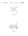
- FIG. 2 is a cutaway perspective view of two adjoining stiffeners of the structure of FIG. 1,
- FIG. 3 is a cross-sectional top plan view of the adjoining stiffeners of FIG. 2,
- FIG. 4 is an alternative embodiment stiffener arrangement for a composite structure
- FIG. 5 is an alternative embodiment stiffener arrangement for a composite structure
- FIG. 6 is an alternative embodiment stiffener arrangement for a composite structure
- FIG. 7 is a schematic representation of a multi-step process for making the stiffeners.
- a composite structure having fiber reinforced serpentine stiffeners is provided.
- the stiffeners merge toward, join with and then diverge from adjacent stiffeners to provide multi-directional continuous fiber reinforcements.
- the stiffeners provide fiber continuity for the axial and circumferential load paths.
- the serpentine stiffeners are preferably sinusoidal in shape, being shaped like a sine curve or sine wave, as shown in FIGS. 1, 2 and 3.
- the composite structure (10) comprises (a) a reinforcing matrix (12) fixedly adhered to (b) a substrate (14).
- the reinforcing matrix (12) comprises a first serpentine composite stiffener (16) which merges, joins and diverges from a second stiffener (18).
- the stiffeners are preferably mirror images of each other.
- the matrix (12) comprises a plurality of serpentine composite stiffeners (16) which merge toward, join with and diverge from adjacent stiffeners (18).
- each stiffener (16, 18) joins at apex (20) thereof, with adjacent stiffener (18) at base (22) thereof.
- each stiffener (16, 18) has a plurality of long continuous fibers (24) running through the length thereof.
- the serpentine nature of the stiffeners (16, 18) allows for the creation of a matrix (12) which can provide long fiber multidirectional load dispersal.
- the matrix may further include a linear axial, fiber reinforced, stiffener (21) disposed between two serpentine stiffeners and joined therewith.
- a linear axial, fiber reinforced, stiffener (21) disposed between two serpentine stiffeners and joined therewith.
- an alternative embodiment may have the serpentine shape in the form of rectangular bonds (right angle bonds) forming repeating rectangles with the adjacent stiffeners.
- the serpentine shape may be in a form such that of an hour glass shape is formed by adjacent stiffeners.
- each serpentine stiffener (16, 18) comprises a flat top (26), a flat bottom (28), a horizontally sinusoidal left side (first side) (30) extending vertically linearly from said top (26) to said bottom (28), and a sinusoidal right side (second side) (32) extending vertically linearly from said top (26) to said bottom (28) and spaced apart therefrom wherein the sides (30, 32) run in phase (in sinc) with each other provide a uniform thickness between the sides (30, 32) along the length of the stiffener.
- Each serpentine stiffener is positioned between two adjacent serpentine stiffeners and joins with the two adjacent serpentine stiffeners at a plurality of points.
- a method for making a reinforced composite structure (10) involves (a) preparing a serpentine composite plate (44) having a plurality of waves, (b) cutting the plate into a plurality of elongated serpentine stiffener ribs (16, 18), (c) adhering the ribs to a substrate (14), the ribs (16) longitudinally merging from, joining to, and diverging from adjacent ribs (18) to form a stiffener matrix (12) on the substrate (14).
- the process involves the steps of (a) assembly a plurality of layers (40a, b, c, d, e) wherein at least one layer comprises long fibers and at least one layer comprises a metal, and the plurality of layers may optionally be alternating layers of foil and fiber (or optionally mmc monotapes) (b) consolidation of the plurality of layers into a flat plate (42), (c) forming the flat plate into a serpentine plate (waved plate) (44) by pressure forming in matched dies (only one die shown) (46) and (d) cutting the serpentine plate transverse to the waves to make serpentine stiffeners (16, 18).
- composite denotes a material containing a fiber such as a carbonaceous, silica, metal, metal oxide, or ceramic fiber embedded in a resin material such as Epoxy, PMR-15, BMI, PEEU, and metals such as Titanium Copper, and aluminum, and ceramics such as SiC and Al 2 0 3 , of particular use are fibers woven into cloth that is impregnated with a resin and cured via an autoclaving process or press molding to form a hard relatively homogeneous article.
- the composite may be a graphite woven cloth impregnated with a PMR-15 polyimide resin, this includes tape as well as fabric.
Abstract
A stiffened composite is provided exhibiting multi-directional reinforcement with continuous long fibers. The composite has a substrate and serpentine stiffeners adhered thereto. The stiffeners merge toward, join with and diverge from adjacent stiffeners to provide a stiffener matrix on the substrate. The serpentine stiffener permit the matrix to exhibit multi-directional reinforcement with the continuous long fibers within the serpentine ribs. The composite structures are useful as aircraft bypass ducts, and as other composite products.
Description
The Government has rights to this invention pursuant to Contract No. F33615-87-C-2843 awarded by the Department of the Air Force.
1. Field of the Invention
The present invention relates to composite structures, and more particularly to stiffened composite structures and methods thereof.
2. Description of the Related Art
Various composite structures are known such as composite ducts, see, Siewert et al., U.S. Pat. No. 3,757,827, issued Sep. 1, 1973, which is incorporated herein by reference, and various stiffener arrangements for combustor liners in a gas turbine engine are known, see Ekstedt, U.S. Pat. No. 3,793,827, issued Feb. 26, 1974, which is incorporated herein by reference. Some stiffener configurations are designed to stabilize planar structural members against buckling or loads. For example, circumferential stiffeners, also referred to as rings, are placed on pressurized vessels to reduce the bulging effects and axial stiffeners are placed on a cylinder to improve bending and buckling strength.
There are cases when two or more crossing stiffeners are required to provide the stiffness necessary to support the required loads. One such case is the outer ducts in aircraft engines. These ducts, commonly referred to as bypass ducts, act as the backbone of the engine providing a means to transfer and or share internally and externally generated loads between the engine mounts. The aircraft engine bypass duct is subject to internal pressure as well as bending and axial loads. The combination of the bending and axial loads usually requires buckling strength. Buckling strength is usually provided by breaking the shell (planar member) into smaller plates whose edges are stiffened by stiffeners. Usually a two or three member stiffener pattern is used. When the stiffener pattern has two members and the members are normal to each other, the pattern is called a waffle-grid. In the case of a three member stiffener pattern where the members cross at 60 degrees and form equilateral triangles, the pattern is called an isogrid.
In weight sensitive structures, such as aircraft engines, the need to stiffen a shell or panel against bending, out of plane shear or buckling load requirements must be balanced with low profile and less weight. This is the reason that fiber reinforcement of stiffeners is desired.
Prior stiffeners have generally lacked simultaneous continuity of fiber in the load paths for more than one direction. Prior attempts to provide continuous fiber in multi-directional crossing stiffeners have generally involved either (a) only fibers in one of the stiffeners member being continuous or (b) a very laborious lay-up of plies with alternate layers of reinforced plies being fabricated which generally resulted in effectively lower fiber volume fractions.
Consequently, there is a desire to provide a composite stiffener structure for aircraft engine ducts which efficiently allows for maximum utilization of fibers in stiffeners by eliminating the need to cross the stiffeners.
The present invention involves a composite having serpentine shaped stiffeners which merge, join, and diverge in repeating fashion with adjacent stiffeners to provide multi-directional stiffeners. The serpentine shape may be in the nature of angular, waved and/or sinusoidal form forming rectangular, square, or hour glass shapes with adjacent stiffeners, and the use of long bars continuously reinforced with fibers such as titanium matrix composites, permits fiber continuity for the axial as well as circumferential load paths.
FIG. 1 is a perspective view of a stiffened composite structure according to the present invention,
FIG. 2 is a cutaway perspective view of two adjoining stiffeners of the structure of FIG. 1,
FIG. 3 is a cross-sectional top plan view of the adjoining stiffeners of FIG. 2,
FIG. 4 is an alternative embodiment stiffener arrangement for a composite structure,
FIG. 5 is an alternative embodiment stiffener arrangement for a composite structure,
FIG. 6 is an alternative embodiment stiffener arrangement for a composite structure, and
FIG. 7 is a schematic representation of a multi-step process for making the stiffeners.
A composite structure having fiber reinforced serpentine stiffeners is provided. The stiffeners merge toward, join with and then diverge from adjacent stiffeners to provide multi-directional continuous fiber reinforcements. The stiffeners provide fiber continuity for the axial and circumferential load paths.
The serpentine stiffeners are preferably sinusoidal in shape, being shaped like a sine curve or sine wave, as shown in FIGS. 1, 2 and 3.
As best shown in FIG. 1, the composite structure (10) comprises (a) a reinforcing matrix (12) fixedly adhered to (b) a substrate (14).
The reinforcing matrix (12) comprises a first serpentine composite stiffener (16) which merges, joins and diverges from a second stiffener (18). The stiffeners are preferably mirror images of each other. Preferably, the matrix (12) comprises a plurality of serpentine composite stiffeners (16) which merge toward, join with and diverge from adjacent stiffeners (18).
As shown in FIG. 2, the stiffeners (16) join at apex (20) thereof, with adjacent stiffener (18) at base (22) thereof. As best shown in FIG. 3, each stiffener (16, 18) has a plurality of long continuous fibers (24) running through the length thereof. The serpentine nature of the stiffeners (16, 18) allows for the creation of a matrix (12) which can provide long fiber multidirectional load dispersal.
As best shown in FIG. 4, the matrix may further include a linear axial, fiber reinforced, stiffener (21) disposed between two serpentine stiffeners and joined therewith. As shown in FIG. 5, an alternative embodiment may have the serpentine shape in the form of rectangular bonds (right angle bonds) forming repeating rectangles with the adjacent stiffeners. As shown in FIGS. 2,3 and the serpentine shape may be in a form such that of an hour glass shape is formed by adjacent stiffeners. Preferably, each serpentine stiffener (16, 18) comprises a flat top (26), a flat bottom (28), a horizontally sinusoidal left side (first side) (30) extending vertically linearly from said top (26) to said bottom (28), and a sinusoidal right side (second side) (32) extending vertically linearly from said top (26) to said bottom (28) and spaced apart therefrom wherein the sides (30, 32) run in phase (in sinc) with each other provide a uniform thickness between the sides (30, 32) along the length of the stiffener. Each serpentine stiffener is positioned between two adjacent serpentine stiffeners and joins with the two adjacent serpentine stiffeners at a plurality of points.
A method is provided for making a reinforced composite structure (10), the method involves (a) preparing a serpentine composite plate (44) having a plurality of waves, (b) cutting the plate into a plurality of elongated serpentine stiffener ribs (16, 18), (c) adhering the ribs to a substrate (14), the ribs (16) longitudinally merging from, joining to, and diverging from adjacent ribs (18) to form a stiffener matrix (12) on the substrate (14).
In more detail, as shown in FIG. 7, the process (method) involves the steps of (a) assembly a plurality of layers (40a, b, c, d, e) wherein at least one layer comprises long fibers and at least one layer comprises a metal, and the plurality of layers may optionally be alternating layers of foil and fiber (or optionally mmc monotapes) (b) consolidation of the plurality of layers into a flat plate (42), (c) forming the flat plate into a serpentine plate (waved plate) (44) by pressure forming in matched dies (only one die shown) (46) and (d) cutting the serpentine plate transverse to the waves to make serpentine stiffeners (16, 18).
The term composite, for the purposes of this invention, denotes a material containing a fiber such as a carbonaceous, silica, metal, metal oxide, or ceramic fiber embedded in a resin material such as Epoxy, PMR-15, BMI, PEEU, and metals such as Titanium Copper, and aluminum, and ceramics such as SiC and Al2 03, of particular use are fibers woven into cloth that is impregnated with a resin and cured via an autoclaving process or press molding to form a hard relatively homogeneous article. For certain structures, the composite may be a graphite woven cloth impregnated with a PMR-15 polyimide resin, this includes tape as well as fabric. A discussion of this material may be found in an article in the January 1990 issues of Plastics Engineering, entitled "Processing of PMR-15 Prepregs for High Temperature Composites", by Mel Kaniz, which is incorporated herein by reference. Further information concerning suitable materials and definitions may be found in the "Engineering Material & Handbook" by ASM INTERNATIONAL, 1987-1989 or later editions, which is incorporated herein by reference.
Claims (9)
1. A composite structure comprising:
(a) a tubular substrate, and
(b) a plurality of stiffeners adhered to said substrate, wherein each of said stiffeners is a serpentine stiffener which longitudinally merges toward, joins with and then diverges from an adjacent stiffener, wherein each of said serpentine stiffeners comprises a plurality of reinforcing fibers extending longitudinally within said serpentine stiffener.
2. The structure of claim 1 wherein said structure is an aircraft bypass duct.
3. The structure of claim 1 wherein said substrate is a hollow cylindrical substrate.
4. The structure of claim 1 wherein said structure comprises a plurality of serpentine stiffeners wherein each serpentine stiffener longitudinally merges with, joins to and diverges from an adjacent serpentine stiffener.
5. The structure of claim 1 wherein each serpentine stiffener is positioned between two adjacent serpentine stiffeners and joins with the two adjacent serpentine stiffeners at a plurality of points.
6. The structure of claim 1 wherein said serpentine stiffener comprises a flat top, a flat bottom, a sinusoidal left side extending from said top to said bottom, and a sinusoidal right side extending from said top to said bottom and spaced apart from said left side.
7. The structure of claim 6 wherein said serpentine stiffener is substantially rectangular in crosssection transverse to top and bottom walls.
8. The structure of claim 1 wherein said fibers are wave shaped within the stiffener.
9. An aircraft engine comprising:
(a) a bypass duct comprising:
(i) a tubular substrate,
(ii) a plurality of fiber reinforced serpentine stiffeners attached to said substrate, wherein each serpentine stiffener longitudinally merges toward, joins with and then diverges from an adjacent stiffener, said serpentine stiffener comprises a plurality of reinforcing fibers extending longitudinally within said serpentine stiffener, wherein each serpentine stiffener comprises a plurality of reinforcing fibers extending longitudinally within said serpentine stiffener.
Priority Applications (1)
| Application Number | Priority Date | Filing Date | Title |
|---|---|---|---|
| US08/576,249 US5771680A (en) | 1995-12-21 | 1995-12-21 | Stiffened composite structures and method of making thereof |
Applications Claiming Priority (1)
| Application Number | Priority Date | Filing Date | Title |
|---|---|---|---|
| US08/576,249 US5771680A (en) | 1995-12-21 | 1995-12-21 | Stiffened composite structures and method of making thereof |
Publications (1)
| Publication Number | Publication Date |
|---|---|
| US5771680A true US5771680A (en) | 1998-06-30 |
Family
ID=24303588
Family Applications (1)
| Application Number | Title | Priority Date | Filing Date |
|---|---|---|---|
| US08/576,249 Expired - Lifetime US5771680A (en) | 1995-12-21 | 1995-12-21 | Stiffened composite structures and method of making thereof |
Country Status (1)
| Country | Link |
|---|---|
| US (1) | US5771680A (en) |
Cited By (16)
| Publication number | Priority date | Publication date | Assignee | Title |
|---|---|---|---|---|
| US6261395B1 (en) * | 1998-05-15 | 2001-07-17 | Bae Systems Plc | Manufacture of stiffened composite structures |
| US20090169833A1 (en) * | 2007-11-01 | 2009-07-02 | Koon Robert | Highly tailored stiffening for advanced composites |
| US20090324765A1 (en) * | 2007-03-30 | 2009-12-31 | Hauke Lengsfeld | Apparatus for the forming of a lay-up of fibre composite material |
| US20100218483A1 (en) * | 2009-02-27 | 2010-09-02 | United Technologies Corporation | Controlled fan stream flow bypass |
| DE102009056996A1 (en) | 2009-12-04 | 2011-06-09 | Eads Deutschland Gmbh | Stiffening structure for reinforcing planar structure, particularly skin field of fuselage of aircraft, comprises variety of struts with different geometries, where one strut has linear geometry |
| WO2012076308A1 (en) | 2010-12-08 | 2012-06-14 | Bcomp Gmbh | Stiffened thin-walled fibre composite products and method of making same |
| US8628717B2 (en) | 2010-06-25 | 2014-01-14 | The Boeing Company | Composite structures having integrated stiffeners and method of making the same |
| US8636252B2 (en) | 2010-06-25 | 2014-01-28 | The Boeing Company | Composite structures having integrated stiffeners with smooth runouts and method of making the same |
| US8685302B2 (en) | 2012-02-20 | 2014-04-01 | Honeywell International Inc. | Monolithic acoustically-treated composite structures and methods for fabricating the same |
| US8940213B2 (en) | 2010-06-25 | 2015-01-27 | The Boeing Company | Resin infusion of composite parts using a perforated caul sheet |
| US9126374B2 (en) | 2010-09-28 | 2015-09-08 | Russell B. Hanson | Iso-grid composite component |
| US20170016345A1 (en) * | 2015-07-17 | 2017-01-19 | Honeywell International Inc. | Composite structure with load distribution devices, and method for making same |
| US9682514B2 (en) | 2010-06-25 | 2017-06-20 | The Boeing Company | Method of manufacturing resin infused composite parts using a perforated caul sheet |
| US9833930B2 (en) | 2012-10-23 | 2017-12-05 | Albany Engineered Composites, Inc. | Circumferential stiffeners for composite fancases |
| US10137664B2 (en) * | 2014-03-28 | 2018-11-27 | Mitsubishi Heavy Industries, Ltd. | Composite material structure, aircraft wing and aircraft fuselage provided with same, and method for manufacturing composite material structure |
| US11230971B1 (en) * | 2020-10-19 | 2022-01-25 | General Electric Company | Unit cell structures including stiffening patterns |
Citations (28)
| Publication number | Priority date | Publication date | Assignee | Title |
|---|---|---|---|---|
| US2688327A (en) * | 1950-08-11 | 1954-09-07 | Berg Samuel | Colostomy device |
| US2898940A (en) * | 1957-05-13 | 1959-08-11 | Jr Howard W Cole | High pressure hose |
| US3013315A (en) * | 1960-06-03 | 1961-12-19 | Stauffer Chemical Co | Apparatus for centrifugal casting |
| US3018205A (en) * | 1958-02-25 | 1962-01-23 | Barut Victor Jacques | Cellular structure and method of manufacture |
| US3134705A (en) * | 1962-10-15 | 1964-05-26 | Dow Chemical Co | Honeycomb fabrication |
| US3210233A (en) * | 1962-08-27 | 1965-10-05 | Mcdonnell Aircraft Corp | Heat insulating and ablative structure and method of making same |
| US3257253A (en) * | 1962-03-22 | 1966-06-21 | Weyerhaeuser Co | Laminated cellular panel |
| US3272686A (en) * | 1962-03-23 | 1966-09-13 | Corning Glass Works | Structural ceramic bodies and method of making same |
| US3617416A (en) * | 1967-06-23 | 1971-11-02 | Aerojet General Co | Honeycomb structures |
| US3693354A (en) * | 1971-01-22 | 1972-09-26 | Gen Electric | Aircraft engine fan duct burner system |
| US3757827A (en) * | 1969-01-29 | 1973-09-11 | Ge El Co | Lightweight duct and method of making same |
| US3793827A (en) * | 1972-11-02 | 1974-02-26 | Gen Electric | Stiffener for combustor liner |
| US4063847A (en) * | 1974-08-23 | 1977-12-20 | Rolls-Royce (1971) Limited | Gas turbine engine casing |
| USRE30489E (en) * | 1976-05-21 | 1981-01-20 | Brunswick Corporation | Longitudinal load carrying method for fiber reinforced filament wound structures |
| US4285194A (en) * | 1979-04-23 | 1981-08-25 | General Electric Company | Apparatus and method for controlling fan duct flow in a gas turbine engine |
| US4880681A (en) * | 1988-02-26 | 1989-11-14 | Heath Tecna Aerospace, Co. | Low heat output composite |
| US4961685A (en) * | 1988-09-06 | 1990-10-09 | Mtu-Motoren-Und Turbinen-Union Muenchen Gmbh | Protection ring of fiber material for containing fragments of bursting structural components |
| US4968546A (en) * | 1988-02-09 | 1990-11-06 | Kanto Yakin Kogyo K.K. | Component parts for high temperature suffering transfer means |
| US4969623A (en) * | 1989-03-01 | 1990-11-13 | Bernier Rene A | Flight documents organizer |
| US5038834A (en) * | 1988-03-08 | 1991-08-13 | Vsl International Ag | Encasing tubing having continuous bonding enhancing properties |
| US5182906A (en) * | 1990-10-22 | 1993-02-02 | General Electric Company | Hybrid spinner nose configuration in a gas turbine engine having a bypass duct |
| US5211007A (en) * | 1991-04-10 | 1993-05-18 | General Electric Company | Method of pressure-ratio control of gas turbine engine |
| US5222360A (en) * | 1991-10-30 | 1993-06-29 | General Electric Company | Apparatus for removably attaching a core frame to a vane frame with a stable mid ring |
| US5251435A (en) * | 1991-10-30 | 1993-10-12 | General Electric Company | Reverser inner cowl with integral bifurcation walls and core cowl |
| US5305599A (en) * | 1991-04-10 | 1994-04-26 | General Electric Company | Pressure-ratio control of gas turbine engine |
| US5313788A (en) * | 1991-08-07 | 1994-05-24 | General Electric Company | Thrust reversing arrangement for a long duct mixed flow exhaust turbofan engine |
| US5315820A (en) * | 1990-06-28 | 1994-05-31 | Short Brothers Plc | Composite structural component |
| US5556677A (en) * | 1994-01-07 | 1996-09-17 | Composite Development Corporation | Composite shaft structure and manufacture |
-
1995
- 1995-12-21 US US08/576,249 patent/US5771680A/en not_active Expired - Lifetime
Patent Citations (28)
| Publication number | Priority date | Publication date | Assignee | Title |
|---|---|---|---|---|
| US2688327A (en) * | 1950-08-11 | 1954-09-07 | Berg Samuel | Colostomy device |
| US2898940A (en) * | 1957-05-13 | 1959-08-11 | Jr Howard W Cole | High pressure hose |
| US3018205A (en) * | 1958-02-25 | 1962-01-23 | Barut Victor Jacques | Cellular structure and method of manufacture |
| US3013315A (en) * | 1960-06-03 | 1961-12-19 | Stauffer Chemical Co | Apparatus for centrifugal casting |
| US3257253A (en) * | 1962-03-22 | 1966-06-21 | Weyerhaeuser Co | Laminated cellular panel |
| US3272686A (en) * | 1962-03-23 | 1966-09-13 | Corning Glass Works | Structural ceramic bodies and method of making same |
| US3210233A (en) * | 1962-08-27 | 1965-10-05 | Mcdonnell Aircraft Corp | Heat insulating and ablative structure and method of making same |
| US3134705A (en) * | 1962-10-15 | 1964-05-26 | Dow Chemical Co | Honeycomb fabrication |
| US3617416A (en) * | 1967-06-23 | 1971-11-02 | Aerojet General Co | Honeycomb structures |
| US3757827A (en) * | 1969-01-29 | 1973-09-11 | Ge El Co | Lightweight duct and method of making same |
| US3693354A (en) * | 1971-01-22 | 1972-09-26 | Gen Electric | Aircraft engine fan duct burner system |
| US3793827A (en) * | 1972-11-02 | 1974-02-26 | Gen Electric | Stiffener for combustor liner |
| US4063847A (en) * | 1974-08-23 | 1977-12-20 | Rolls-Royce (1971) Limited | Gas turbine engine casing |
| USRE30489E (en) * | 1976-05-21 | 1981-01-20 | Brunswick Corporation | Longitudinal load carrying method for fiber reinforced filament wound structures |
| US4285194A (en) * | 1979-04-23 | 1981-08-25 | General Electric Company | Apparatus and method for controlling fan duct flow in a gas turbine engine |
| US4968546A (en) * | 1988-02-09 | 1990-11-06 | Kanto Yakin Kogyo K.K. | Component parts for high temperature suffering transfer means |
| US4880681A (en) * | 1988-02-26 | 1989-11-14 | Heath Tecna Aerospace, Co. | Low heat output composite |
| US5038834A (en) * | 1988-03-08 | 1991-08-13 | Vsl International Ag | Encasing tubing having continuous bonding enhancing properties |
| US4961685A (en) * | 1988-09-06 | 1990-10-09 | Mtu-Motoren-Und Turbinen-Union Muenchen Gmbh | Protection ring of fiber material for containing fragments of bursting structural components |
| US4969623A (en) * | 1989-03-01 | 1990-11-13 | Bernier Rene A | Flight documents organizer |
| US5315820A (en) * | 1990-06-28 | 1994-05-31 | Short Brothers Plc | Composite structural component |
| US5182906A (en) * | 1990-10-22 | 1993-02-02 | General Electric Company | Hybrid spinner nose configuration in a gas turbine engine having a bypass duct |
| US5211007A (en) * | 1991-04-10 | 1993-05-18 | General Electric Company | Method of pressure-ratio control of gas turbine engine |
| US5305599A (en) * | 1991-04-10 | 1994-04-26 | General Electric Company | Pressure-ratio control of gas turbine engine |
| US5313788A (en) * | 1991-08-07 | 1994-05-24 | General Electric Company | Thrust reversing arrangement for a long duct mixed flow exhaust turbofan engine |
| US5251435A (en) * | 1991-10-30 | 1993-10-12 | General Electric Company | Reverser inner cowl with integral bifurcation walls and core cowl |
| US5222360A (en) * | 1991-10-30 | 1993-06-29 | General Electric Company | Apparatus for removably attaching a core frame to a vane frame with a stable mid ring |
| US5556677A (en) * | 1994-01-07 | 1996-09-17 | Composite Development Corporation | Composite shaft structure and manufacture |
Cited By (32)
| Publication number | Priority date | Publication date | Assignee | Title |
|---|---|---|---|---|
| US6261395B1 (en) * | 1998-05-15 | 2001-07-17 | Bae Systems Plc | Manufacture of stiffened composite structures |
| US9149990B2 (en) * | 2007-03-30 | 2015-10-06 | Airbus Operations Gmbh | Apparatus for the forming of a lay-up of fibre composite material |
| US20090324765A1 (en) * | 2007-03-30 | 2009-12-31 | Hauke Lengsfeld | Apparatus for the forming of a lay-up of fibre composite material |
| US20090169833A1 (en) * | 2007-11-01 | 2009-07-02 | Koon Robert | Highly tailored stiffening for advanced composites |
| US7897239B2 (en) * | 2007-11-01 | 2011-03-01 | Lockheed Martin Corporation | Highly tailored stiffening for advanced composites |
| US20100218483A1 (en) * | 2009-02-27 | 2010-09-02 | United Technologies Corporation | Controlled fan stream flow bypass |
| US8181441B2 (en) | 2009-02-27 | 2012-05-22 | United Technologies Corporation | Controlled fan stream flow bypass |
| DE102009056996A1 (en) | 2009-12-04 | 2011-06-09 | Eads Deutschland Gmbh | Stiffening structure for reinforcing planar structure, particularly skin field of fuselage of aircraft, comprises variety of struts with different geometries, where one strut has linear geometry |
| DE102009056996B4 (en) | 2009-12-04 | 2021-10-21 | Airbus Defence and Space GmbH | Stiffening structure for stiffening a fabric and aircraft |
| US8628717B2 (en) | 2010-06-25 | 2014-01-14 | The Boeing Company | Composite structures having integrated stiffeners and method of making the same |
| US8940213B2 (en) | 2010-06-25 | 2015-01-27 | The Boeing Company | Resin infusion of composite parts using a perforated caul sheet |
| US8636252B2 (en) | 2010-06-25 | 2014-01-28 | The Boeing Company | Composite structures having integrated stiffeners with smooth runouts and method of making the same |
| US9440402B2 (en) | 2010-06-25 | 2016-09-13 | The Boeing Company | Composite structures having integrated stiffeners with smooth runouts and method of making the same |
| US9682514B2 (en) | 2010-06-25 | 2017-06-20 | The Boeing Company | Method of manufacturing resin infused composite parts using a perforated caul sheet |
| US9682516B2 (en) | 2010-06-25 | 2017-06-20 | The Boeing Company | Resin infusion of composite parts using a perforated caul sheet |
| US10335905B2 (en) | 2010-09-28 | 2019-07-02 | United Technologies Corporation | Iso-grid composite component |
| US9126374B2 (en) | 2010-09-28 | 2015-09-08 | Russell B. Hanson | Iso-grid composite component |
| US9789570B2 (en) | 2010-09-28 | 2017-10-17 | United Technologies Corporation | Iso-grid composite component |
| US10071528B2 (en) | 2010-12-08 | 2018-09-11 | Bcomp Sa | Stiffened thin-walled fibre composite products and method of making same |
| WO2012076308A1 (en) | 2010-12-08 | 2012-06-14 | Bcomp Gmbh | Stiffened thin-walled fibre composite products and method of making same |
| US8685302B2 (en) | 2012-02-20 | 2014-04-01 | Honeywell International Inc. | Monolithic acoustically-treated composite structures and methods for fabricating the same |
| US9469390B2 (en) | 2012-02-20 | 2016-10-18 | Honeywell International Inc. | Monolithic acoustically-treated composite structures and methods for fabricating the same |
| US9833930B2 (en) | 2012-10-23 | 2017-12-05 | Albany Engineered Composites, Inc. | Circumferential stiffeners for composite fancases |
| US10016913B2 (en) | 2012-10-23 | 2018-07-10 | Albany Engineered Composites, Inc. | Circumferential stiffeners for composite fancases |
| US11485048B2 (en) | 2012-10-23 | 2022-11-01 | Albany Engineered Composites, Inc. | Circumferential stiffeners for composite fancases |
| US10052796B2 (en) | 2012-10-23 | 2018-08-21 | Albany Engineered Composites, Inc. | Circumferential stiffeners for composite fancases |
| US10150229B2 (en) | 2012-10-23 | 2018-12-11 | Albany Engineered Composites, Inc. | Circumferential stiffeners for composite fancases |
| US10137664B2 (en) * | 2014-03-28 | 2018-11-27 | Mitsubishi Heavy Industries, Ltd. | Composite material structure, aircraft wing and aircraft fuselage provided with same, and method for manufacturing composite material structure |
| US20170016345A1 (en) * | 2015-07-17 | 2017-01-19 | Honeywell International Inc. | Composite structure with load distribution devices, and method for making same |
| US10030535B2 (en) * | 2015-07-17 | 2018-07-24 | Honeywell International Inc. | Composite structure with load distribution devices, and method for making same |
| US11230971B1 (en) * | 2020-10-19 | 2022-01-25 | General Electric Company | Unit cell structures including stiffening patterns |
| US11608780B2 (en) | 2020-10-19 | 2023-03-21 | General Electric Company | Unit cell structures including stiffening patterns |
Similar Documents
| Publication | Publication Date | Title |
|---|---|---|
| US5771680A (en) | Stiffened composite structures and method of making thereof | |
| US5062589A (en) | Fiber reinforced pressure bulkhead with integrated frame | |
| Kim | Fabrication and testing of composite isogrid stiffened cylinder | |
| EP1801428B1 (en) | Metallic local reinforcement for heavy loaded joints of composite components | |
| JPH0661885B2 (en) | Composite element with variable density core | |
| Raju et al. | Three-dimensional analysis of [0/90] s and [90/0] s laminates with a central circular hole | |
| US20060060726A1 (en) | Polyimide resin and carbon fiber molded tube clamp | |
| Falzon | The behaviour of damage tolerant hat-stiffened composite panels loaded in uniaxial compression | |
| Vitale et al. | Manufacturing and compressive response of ultra-lightweight CFRP cores | |
| WO2005049933A1 (en) | Sandwich panel and a method of producing a sandwich panel | |
| Walker et al. | Optimal design of symmetrically laminated plates for minimum deflection and weight | |
| Ueda et al. | Three-dimensional printing of locally bendable short carbon fiber reinforced polymer composites | |
| Fukunaga et al. | Optimum design of composite structures for shape, layer angle and layer thickness distributions | |
| Studer et al. | Local reinforcement of aerospace structures using co-curing RTM of metal foil hybrid composites | |
| Brown et al. | Lightweight composite truss section decking | |
| Kam et al. | Optimum design of laminated composite foam-filled sandwich plates subjected to strength constraint | |
| Tauchert et al. | Optimum thermoelastic design of laminated plates | |
| Schoutens | Design Optimization of Metal Matrix Composites | |
| Elaldi et al. | Buckling and post-buckling behavior of compression loaded composite panels with hat stiffeners | |
| Ko et al. | Control of fiber architecture for tough net-shaped structural composites | |
| Goetz et al. | Trees as a model for technical fibre composites | |
| Lee et al. | Design, analyses, manufacture and experimental performance of hat-stiffened composite panel | |
| Wang et al. | Improved structural efficiency in composite manufacturing via hammered printing for large-curvature fiber paths | |
| Dullea Jr | The bi-composite transition joint | |
| Susuki | Strength optimization of multidirectional laminates in an in-plane combined stress state |
Legal Events
| Date | Code | Title | Description |
|---|---|---|---|
| AS | Assignment |
Owner name: AIR FORCE, UNITED STATES, VIRGINIA Free format text: CONFIRMATORY LICENSE;ASSIGNOR:GENERAL ELECTRIC COMPANY;REEL/FRAME:008843/0267 Effective date: 19960321 |
|
| STCF | Information on status: patent grant |
Free format text: PATENTED CASE |
|
| FPAY | Fee payment |
Year of fee payment: 4 |
|
| FPAY | Fee payment |
Year of fee payment: 8 |
|
| FPAY | Fee payment |
Year of fee payment: 12 |