US5790034A - Retrofittable remote controlled door lock system - Google Patents
Retrofittable remote controlled door lock system Download PDFInfo
- Publication number
- US5790034A US5790034A US08/847,227 US84722797A US5790034A US 5790034 A US5790034 A US 5790034A US 84722797 A US84722797 A US 84722797A US 5790034 A US5790034 A US 5790034A
- Authority
- US
- United States
- Prior art keywords
- receiver
- transmitter
- deadbolt
- signal
- lock
- Prior art date
- Legal status (The legal status is an assumption and is not a legal conclusion. Google has not performed a legal analysis and makes no representation as to the accuracy of the status listed.)
- Expired - Fee Related
Links
Images


Classifications
-
- E—FIXED CONSTRUCTIONS
- E05—LOCKS; KEYS; WINDOW OR DOOR FITTINGS; SAFES
- E05B—LOCKS; ACCESSORIES THEREFOR; HANDCUFFS
- E05B47/00—Operating or controlling locks or other fastening devices by electric or magnetic means
- E05B47/0001—Operating or controlling locks or other fastening devices by electric or magnetic means with electric actuators; Constructional features thereof
- E05B47/0012—Operating or controlling locks or other fastening devices by electric or magnetic means with electric actuators; Constructional features thereof with rotary electromotors
-
- E—FIXED CONSTRUCTIONS
- E05—LOCKS; KEYS; WINDOW OR DOOR FITTINGS; SAFES
- E05B—LOCKS; ACCESSORIES THEREFOR; HANDCUFFS
- E05B47/00—Operating or controlling locks or other fastening devices by electric or magnetic means
- E05B47/0001—Operating or controlling locks or other fastening devices by electric or magnetic means with electric actuators; Constructional features thereof
- E05B2047/0014—Constructional features of actuators or power transmissions therefor
- E05B2047/0018—Details of actuator transmissions
- E05B2047/002—Geared transmissions
-
- E—FIXED CONSTRUCTIONS
- E05—LOCKS; KEYS; WINDOW OR DOOR FITTINGS; SAFES
- E05B—LOCKS; ACCESSORIES THEREFOR; HANDCUFFS
- E05B47/00—Operating or controlling locks or other fastening devices by electric or magnetic means
- E05B2047/0091—Retrofittable electric locks, e.g. an electric module can be attached to an existing manual lock
-
- E—FIXED CONSTRUCTIONS
- E05—LOCKS; KEYS; WINDOW OR DOOR FITTINGS; SAFES
- E05B—LOCKS; ACCESSORIES THEREFOR; HANDCUFFS
- E05B63/00—Locks or fastenings with special structural characteristics
- E05B63/0004—Additional locks added to existing lock arrangements
-
- Y—GENERAL TAGGING OF NEW TECHNOLOGICAL DEVELOPMENTS; GENERAL TAGGING OF CROSS-SECTIONAL TECHNOLOGIES SPANNING OVER SEVERAL SECTIONS OF THE IPC; TECHNICAL SUBJECTS COVERED BY FORMER USPC CROSS-REFERENCE ART COLLECTIONS [XRACs] AND DIGESTS
- Y10—TECHNICAL SUBJECTS COVERED BY FORMER USPC
- Y10T—TECHNICAL SUBJECTS COVERED BY FORMER US CLASSIFICATION
- Y10T292/00—Closure fasteners
- Y10T292/08—Bolts
- Y10T292/096—Sliding
- Y10T292/1014—Operating means
- Y10T292/1021—Motor
-
- Y—GENERAL TAGGING OF NEW TECHNOLOGICAL DEVELOPMENTS; GENERAL TAGGING OF CROSS-SECTIONAL TECHNOLOGIES SPANNING OVER SEVERAL SECTIONS OF THE IPC; TECHNICAL SUBJECTS COVERED BY FORMER USPC CROSS-REFERENCE ART COLLECTIONS [XRACs] AND DIGESTS
- Y10—TECHNICAL SUBJECTS COVERED BY FORMER USPC
- Y10T—TECHNICAL SUBJECTS COVERED BY FORMER US CLASSIFICATION
- Y10T70/00—Locks
- Y10T70/50—Special application
- Y10T70/5889—For automotive vehicles
- Y10T70/5973—Remote control
-
- Y—GENERAL TAGGING OF NEW TECHNOLOGICAL DEVELOPMENTS; GENERAL TAGGING OF CROSS-SECTIONAL TECHNOLOGIES SPANNING OVER SEVERAL SECTIONS OF THE IPC; TECHNICAL SUBJECTS COVERED BY FORMER USPC CROSS-REFERENCE ART COLLECTIONS [XRACs] AND DIGESTS
- Y10—TECHNICAL SUBJECTS COVERED BY FORMER USPC
- Y10T—TECHNICAL SUBJECTS COVERED BY FORMER US CLASSIFICATION
- Y10T70/00—Locks
- Y10T70/70—Operating mechanism
- Y10T70/7051—Using a powered device [e.g., motor]
- Y10T70/7062—Electrical type [e.g., solenoid]
- Y10T70/7068—Actuated after correct combination recognized [e.g., numerical, alphabetical, or magnet[s] pattern]
-
- Y—GENERAL TAGGING OF NEW TECHNOLOGICAL DEVELOPMENTS; GENERAL TAGGING OF CROSS-SECTIONAL TECHNOLOGIES SPANNING OVER SEVERAL SECTIONS OF THE IPC; TECHNICAL SUBJECTS COVERED BY FORMER USPC CROSS-REFERENCE ART COLLECTIONS [XRACs] AND DIGESTS
- Y10—TECHNICAL SUBJECTS COVERED BY FORMER USPC
- Y10T—TECHNICAL SUBJECTS COVERED BY FORMER US CLASSIFICATION
- Y10T70/00—Locks
- Y10T70/70—Operating mechanism
- Y10T70/7051—Using a powered device [e.g., motor]
- Y10T70/7062—Electrical type [e.g., solenoid]
- Y10T70/7113—Projected and retracted electrically
Definitions
- the present invention relates to door locks, and in particular, to a door lock system utilizing a wireless remote controlled deadbolt door lock and panic alarm system.
- Deadbolt locks are generally safer than normal door knob locks since the deadbolt is positioned deeper within the door frame than the corresponding bolt of normal door knob locks to better inhibit the door from being forced open.
- having to take the time upon entry to open any lock, or worse yet, both a door knob lock and a deadbolt lock is at least an inconvenience, but at worst it increases the time one remains vulnerable.
- a wireless remote controlled deadbolt operating system is provided which is adapted to retrofit on an existing deadbolt lock so that the lock can be automatically opened in an expedient manner at the appropriate time as one approaches the door.
- Conventional deadbolt locks typically have a deadbolt, a deadbolt receiver, and an actuator located on an interior side of the closure.
- the lock system comprises a module which fits over a conventional existing deadbolt and has a drive means which is physically engaged with a portion of the existing deadbolt so as to operate same, to unlock the deadbolt, upon a signal received from a wireless remote transmitter.
- a lock system for opening a conventional deadbolt lock of a securing closure.
- the system has a wireless remote transmitter for selectively transmitting electromagnetic signals to a receiver.
- the receiver is able to respond to the signals and then activate a drive means that is mounted on the interior side of the closure and attached to the actuator of the deadbolt lock.
- a panic alarm may be incorporated into the system, and engageable by the receiver upon receipt of a signal from the transmitter.
- a lock system for opening a conventional deadbolt lock wherein the system utilizes a remote transmitter, a door module unit for operating the deadbolt lock, and a separate wall module unit for operating safety components such as the panic alarm or lights.
- the door module of the second embodiment is very similar to that of the first embodiment.
- the wall module has a receiver of its own that is responsive to a signal received from the transmitter.
- the wall module includes a panic alarm that is powered by direct current.
- the direct current is transformed from an alternating current that is input into to the wall module.
- the alternating current is also connected to a relay that is selectively activated by the receiver of the wall module to operate lights surrounding the lock.
- the transmitter of the second embodiment can be used to operate a conventional garage door opener in combination with the door lock system.
- FIG. 1 is a partial cross-sectional elevation view of a conventional deadbolt lock
- FIG. 2 illustrates schematically a transmitter used in accordance with the system of the present invention
- FIG. 3 is a schematic elevation view of the door module of a first embodiment of the present invention.
- FIG. 4 is a schematic elevation view of a second embodiment of the present invention having both a door module and a wall module;
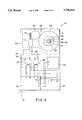
- FIG. 5 is a side elevational view showing the deadbolt lock in partial cross-section and schematically illustrating portions of the door module.
- a conventional deadbolt lock 5 comprising a deadbolt 10 and a deadbolt retainer channel 12 for retaining the deadbolt 10 in a retracted position when the deadbolt lock is unlocked.
- a deadbolt receiver channel 14 is longitudinally positioned opposite and adjacent to the retainer channel 12, for receiving the deadbolt 10 when the deadbolt lock 5 is in a locked position.
- the retainer channel 12 is located within a securing closure, such as a door, and the receiver channel 14 is located along the border of an opening, such as a door frame.
- Deadbolt lock 10 is typically manually engageable and disengageable by an actuator 16 (whose handle 15 is shown in dashed lines).
- actuator 16 whose handle 15 is shown in dashed lines
- Shaft 16a is shown as having a square-shaped end view, but some commonly known locks have different shapes for shaft 16a.
- deadbolt locks made by Schlage have a shape that is almost square, except one of the sides of the would-be square shaft is slightly rounded.
- deadbolt locks made by Quickset utilize a thin rectangular shaft for the end view of shaft 16a.
- Actuator 16 has gear teeth 17 which cooperate with corresponding gear teeth 18 on deadbolt 10, so that rotation of handle 15 extends and retracts deadbolt 10 into and out of channel 14.
- Gear teeth 17 are disposed only in that region near the corresponding gear teeth 18 so that a plate 16c (shown in dashed lines), having a hole in the center, can surround the actuator 16 to keep actuator 16 and lock 5 properly positioned, e.g. by screws or the like, once plate 16c is affixed to the door.
- a plate 16c shown in dashed lines
- the present invention is adaptable to any type of actuator by cooperating with the actuator 16 and providing the requisite force in the direction needed for operating the deadbolt lock 5.
- FIG. 2 there is shown a four channel hand-held wireless remote controller transmitter 20 for activating the various components of the system of the invention as discussed below.
- This transmitter 20 is conventional and can usually be purchased at any hobby or consumer electronics stores such as Radio Shack.
- Each of the four buttons 21, 22, 23 and 24 of transmitter 20 can send an electromagnetic (em) signal 26, in the form of waves of em radiation such as radio frequency, to the surrounding vicinity.
- Each of the buttons 21, 22, 23 and 24 can be programmed to activate any function of the system individually, or a combination of functions.
- Using a four channel transmitter and receiver by Visonic enables 68 billion rolling codes to be implemented for realizing a high degree of security to prevent unauthorized activation of the functions.
- FIG. 3 is a schematic illustration of a door module component 50.
- Door module 50 is adapted to interface or cooperate with existing deadbolt lock 5.
- Door module 50 securely mounts about deadbolt lock 5 so as to be able to effect the necessary deadbolt operating motions.
- handle 15 and plate 16c are removed, thus exposing square shaft 16a.
- Door module 50 has a retrofittable drive module 56 that comprises drive means in the form of a motor 57 which has a bi-directional screw-type output shaft 58 which cooperates with a gear means 60.
- drive means in the form of a motor 57 which has a bi-directional screw-type output shaft 58 which cooperates with a gear means 60.
- gear means 60 is shown in FIG. 3 as including a small gear 62 that translates rotational force from motor output shaft 58 to a large gear 64.
- the gear ratios must be sufficient, based on the driving force of motor 57, to overcome the usual frictional forces involved with operating standard deadbolt locks.
- FIG. 3 shows gear 64 as having a circular opening 65 for receiving a part 66 and a rubber O-ring 78.
- Part 66 has a square opening 68 in the center that allows the passage of square shaft 16a through a face (not shown) of door module 50.
- a replacement plate 70 is used to engage actuator 16 in the way that removed plate 16c previously engaged actuator 16, but replacement plate 70 is used instead so as to ensure a proper fit with door module 50.
- a replacement handle or knob 76 shown in dashed lines, can be placed on the end of shaft 16a that extends out of component 50 to provide a means for continued manual operation of deadbolt lock 5 without transmitter 20.
- door module 50 is affixed to deadbolt lock 5, and/or the door which deadbolt lock 5 is intended to lock, by any conventional means such as mechanical fasteners, screws, adhesive, etc.
- Door module 50 must be secured so that drive module 56 can move actuator 16 in the desired direction to operate lock 5.
- Power source 80 can be any suitable power source that supplies the type of power required by the components of the system.
- the illustrated bi-directional motor 57 uses a direct current (DC) battery.
- DC direct current
- AC alternating current
- power source 80 is a 12 volt DC battery comprised of two 6 volt camera "T" type batteries connected in series that have a positive contact P and a negative contact N and are connected to a receiver 82 at contacts P' and N', respectively.
- receiver 82 In order to activate the system, receiver 82 must be capable of receiving at least one of the plurality of signals 26 generated by transmitter 20 to then activate a particular function of the system. Receiver 82 is shown as being connected to power source 80 so that receiver 82 can generate an output signal upon receiving a transmitted signal from transmitter 20. Each output signal generated by the receiver 82 activates a particular function of the system.
- the receiver 82 when one of the buttons 21, 22, 23 or 24 of transmitter 20 is pushed for operating the deadbolt lock 5, the receiver 82 generates an output signal to operate connecting means 84 so that drive motor 57 is connected to power source 80 and the deadbolt lock 5 is actually engaged or disengaged.
- the connecting means 84 provides this alternating action by supplying DC in the opposite direction to motor 57.
- Connecting means 84 is shown in FIG. 3 as comprising a double pole, double throw (DPDT) relay.
- DPDT double pole, double throw
- the relay of connecting means 84 is shown as having a pair of primary coils 86 that are each supplied with current from the output signal of the receiver 82 along lines connected to contacts A and B, and C and D, respectively. Current through a primary coil induces a magnetic field that attracts the corresponding switch 88 to close the circuit and connect drive motor 57 with power source 80.
- any connecting means that closes the electrical circuit to supply the requisite power is suitable.
- a panic alarm 90 can be operatively connected, at contacts X and Y, to receiver 82 at contacts X' and Y', and activated by other signals from the transmitter 20, or simultaneously activated by the same signal that operates the deadbolt lock 5.
- FIG. 4 illustrates a schematic view of a second embodiment of the present invention comprising a wall module 100 and a door module 50'.
- Door module 50' is very similar to door module 50 except that instead of the panic alarm 90 being located in the door module so as in the first embodiment, panic alarm 90 is now a part of wall module 100.
- Panic alarm 90 is connected to receiver 102. Upon receipt of an appropriate signal from transmitter 20, panic alarm 90 is activated. Panic alarm 90 can be a 200 decibel 12 volt "warble" siren which produces a loud noise for attracting attention of passers-by when the user of the system is in a panic situation.
- Wall module 100 is supplied with power by an input power source 104 that can be any suitable power source.
- Input power source 104 shown in FIG. 4 is a wall socket plug that connects to alternating current (AC) source supplied by a typical AC socket, having two input lines L1 and L2 and a grounded line G, that is found in most homes.
- AC alternating current
- Input power source 104 is connected to convertor 110 that converts AC into DC. This conversion occurs by passing AC into a transformer 112 that is connected to output current and to a pair of diodes 116 and 118 that are in turn connected to the receiver 102.
- the diodes 116, 118 are oppositely oriented and diode 116 is connected in parallel to a capacitor 120 that helps provide a more stable wave form of current from converter 110 to receiver 102.
- Receiver 102 is also connected to a relay 130.
- Relay 130 is connected to an output 132 that supplies AC upon receiving an appropriate signal from transmitter 20.
- AC power can thus be supplied to at least one safety component such as lights for illuminating the interior of the home having deadbolt lock 5 or exterior lights that illuminate the area surrounding lock 5.
- one signal activation button can be used to transmit a signal type that is used to activate a remote-controlled garage door opener which could be of any conventional type.
- transmitter 20 can be used in combination with the inventive system to activate both the door opener and the garage door opener.
- FIG. 5 illustrates a side view of door module 50 or 50' to more clearly show how door module 50 or 50' is affixed to a door having a deadbolt lock 5.
- FIG. 5 assists in understanding the cooperation between shaft 16a, part 66, O-ring 78, and gear 64.
- Shaft 16a is securely engaged with part 66, and O-ring 78 supplies sufficient friction to transmit the operating motion from gear 64 to part 66, and thus shaft 16a.
- O-ring 78 allows for slippage so that if handle 76 is rotated, shaft 16a is rotated, but gear 64 remains stationary due largely to the stronger frictional forces internal to the cooperation between gear means 60 and motor 57.
Abstract
Description
Claims (19)
Priority Applications (1)
| Application Number | Priority Date | Filing Date | Title |
|---|---|---|---|
| US08/847,227 US5790034A (en) | 1997-05-01 | 1997-05-01 | Retrofittable remote controlled door lock system |
Applications Claiming Priority (1)
| Application Number | Priority Date | Filing Date | Title |
|---|---|---|---|
| US08/847,227 US5790034A (en) | 1997-05-01 | 1997-05-01 | Retrofittable remote controlled door lock system |
Publications (1)
| Publication Number | Publication Date |
|---|---|
| US5790034A true US5790034A (en) | 1998-08-04 |
Family
ID=25300120
Family Applications (1)
| Application Number | Title | Priority Date | Filing Date |
|---|---|---|---|
| US08/847,227 Expired - Fee Related US5790034A (en) | 1997-05-01 | 1997-05-01 | Retrofittable remote controlled door lock system |
Country Status (1)
| Country | Link |
|---|---|
| US (1) | US5790034A (en) |
Cited By (46)
| Publication number | Priority date | Publication date | Assignee | Title |
|---|---|---|---|---|
| US6032500A (en) * | 1997-04-18 | 2000-03-07 | Stephen C. Cohen | Kit for retrofitting a door with a security lock system |
| US6035676A (en) * | 1997-06-02 | 2000-03-14 | Hudspeth; Chad W. | System for remote operation of a deadbolt lock |
| US6062612A (en) * | 1998-09-22 | 2000-05-16 | Taiwan Fu Hsing Industrial Co., Ltd. | Remotely controllable lock |
| US6092404A (en) * | 1998-06-01 | 2000-07-25 | Intellikey Corporation | Electronically actuated cargo door lock assembly |
| US6216502B1 (en) * | 2000-04-04 | 2001-04-17 | Thomas Cannella | Keyless locking system |
| US6244084B1 (en) * | 1998-02-27 | 2001-06-12 | Tod L. Warmack | Remote control lock device |
| US6282931B1 (en) | 1996-09-13 | 2001-09-04 | Access Technologies, Inc. | Electrically operated actuator and method |
| US6334636B1 (en) * | 2000-08-09 | 2002-01-01 | Taiwan Fu Hsing Industrial Co., Ltd. | Remotely controllable lock |
| US6382005B1 (en) | 1999-10-18 | 2002-05-07 | Bryan A. White | Garage door locking apparatus |
| US6388559B1 (en) | 1998-12-22 | 2002-05-14 | Lucent Technologies, Inc. | Remote control device and a method of using the same |
| US6454324B1 (en) * | 2000-08-25 | 2002-09-24 | John H. Lewis | Electronic door control and light |
| US20020196123A1 (en) * | 2001-06-26 | 2002-12-26 | The Procter & Gamble Company | Portable locking systems |
| US6580355B1 (en) * | 1999-06-11 | 2003-06-17 | T.K.M. Unlimited, Inc. | Remote door entry system |
| US6588153B1 (en) | 1999-08-10 | 2003-07-08 | The Stanley Works | Power door kit |
| US6658905B1 (en) * | 2002-07-18 | 2003-12-09 | Hui-Hua Hsieh | Remote-controlled door lock |
| US6666054B1 (en) * | 2002-07-25 | 2003-12-23 | Hui-Hua Hsieh | Remote-controlled door lock |
| KR20040004775A (en) * | 2002-07-05 | 2004-01-16 | 블루솔텍(주) | Main Key Door Locking Device |
| US6739164B2 (en) * | 1998-02-27 | 2004-05-25 | Todd Warmack | Remote control lock device |
| US20040112100A1 (en) * | 2002-12-11 | 2004-06-17 | Martin Clifford E. | Electronic door locking apparatus |
| US20040113754A1 (en) * | 2002-08-29 | 2004-06-17 | Kabushiki Kaisha Tokai Rika Denki Seisakusho | Lighting system |
| US20040187532A1 (en) * | 2003-03-28 | 2004-09-30 | Hui-Hua Hsieh | Remote-controlled lock |
| US20050132766A1 (en) * | 2003-12-22 | 2005-06-23 | Milo Thomas K. | Lock assembly |
| US20050179544A1 (en) * | 2002-04-30 | 2005-08-18 | Sutton Patrick R. | Security system |
| US20060117819A1 (en) * | 2004-12-07 | 2006-06-08 | Kilbourne Mark W | Universal remote deadbolt adapter |
| US20060283219A1 (en) * | 2003-09-04 | 2006-12-21 | David Bendz | Device at lock |
| US20070056338A1 (en) * | 2005-09-13 | 2007-03-15 | Eaton Corporation | Lock device and system employing a door lock device |
| US20070109097A1 (en) * | 2005-08-24 | 2007-05-17 | Innerloc, Llc, A Texas Limited Liability Corporation | Internal locking apparatus and methods for making and using same |
| US20070115094A1 (en) * | 2004-03-12 | 2007-05-24 | Joachim Gillert | Locking cylinder and closing method |
| US20070125621A1 (en) * | 2005-12-06 | 2007-06-07 | Locknet, Llc | Token Operated Access Control System |
| US20070262739A1 (en) * | 2006-03-15 | 2007-11-15 | Anderson Troy A | Vertically-mounted garage door operator |
| US20080011032A1 (en) * | 2006-07-17 | 2008-01-17 | Groff John K | Remotely operable door lock interface system |
| US20080066505A1 (en) * | 2006-09-19 | 2008-03-20 | Imperial Usa, Ltd. | Lock assembly with anti-panic feature and associated method |
| US20080115543A1 (en) * | 2006-11-17 | 2008-05-22 | Electronics And Telecommunications Research Institute | Door management system for field service and delivery personnel |
| US20080258867A1 (en) * | 2007-04-17 | 2008-10-23 | Cade Harris | Recreational vehicle wireless keyless power door lock |
| US20080296912A1 (en) * | 2007-05-29 | 2008-12-04 | Whitner Douglas E | Remote door access device |
| US20090084147A1 (en) * | 2007-09-28 | 2009-04-02 | Aiphone Co., Ltd. | Electric lock device |
| US20100300162A1 (en) * | 2009-06-01 | 2010-12-02 | Cappuccio Louis W | Remote control cam locking system |
| US20120073339A1 (en) * | 2010-09-17 | 2012-03-29 | Shagen Sr John A | Emergency Garage door arm release |
| CN102787758A (en) * | 2011-05-19 | 2012-11-21 | 多玛两合有限公司 | Electronic unit for a blocking device and locking system |
| CN104863424A (en) * | 2015-04-13 | 2015-08-26 | 许昌学院 | Novel unlocking machinery anti-theft device |
| DE102015102497A1 (en) * | 2015-02-20 | 2016-08-25 | Hörmann KG Antriebstechnik | Remote-controlled building closure drive and uses thereof |
| US20180061163A1 (en) * | 2016-08-30 | 2018-03-01 | Candy House Inc. | Control device for a door lock |
| US9982461B1 (en) | 2015-05-07 | 2018-05-29 | Mark W. Kilbourne | Deadbolt and passage lock adapter |
| US20200248479A1 (en) * | 2015-10-20 | 2020-08-06 | Xiamen Aerolite Technology Co., Ltd. | Device of wireless controlling a lock and a method of preventing unlocking from outer side |
| US11021894B1 (en) * | 2017-11-14 | 2021-06-01 | Smart Armor Protected, LLC | Power-activated cam lock |
| US11168491B2 (en) | 2018-07-13 | 2021-11-09 | Joseph Michael Szerszen | Emergency door lock illumination apparatus |
Citations (13)
| Publication number | Priority date | Publication date | Assignee | Title |
|---|---|---|---|---|
| US4074269A (en) * | 1976-06-16 | 1978-02-14 | Justin Hartley | Burglar alarm for use with an automatic garage door opener |
| US4802353A (en) * | 1987-08-07 | 1989-02-07 | Intelock Corporation | Battery-powered door lock assembly and method |
| US4854143A (en) * | 1987-08-07 | 1989-08-08 | Intelock Corporation | Bolt assembly and method |
| US4946207A (en) * | 1987-10-03 | 1990-08-07 | Newman Tonks Security Limited | Electrically controlled locks |
| US4984441A (en) * | 1988-08-02 | 1991-01-15 | Mauer Gmbh | Electrically controlled bolt lock |
| US5083448A (en) * | 1988-11-25 | 1992-01-28 | Oy Abloy Security Ltd. | Electromechanical door lock |
| US5263347A (en) * | 1992-09-21 | 1993-11-23 | Allbaugh Mark E | Remote control deadlock bolt for cars |
| US5386713A (en) * | 1991-03-07 | 1995-02-07 | Wilson; Bert | Remote control car deadbolt lock |
| US5404737A (en) * | 1992-04-01 | 1995-04-11 | Roto Frank Eisenwarenfabrik Aktien | Electrically and manually key-controlled lock |
| US5437174A (en) * | 1992-11-17 | 1995-08-01 | David Sokol | Retrofittable electronic and mechanical door lock system |
| US5499014A (en) * | 1994-07-01 | 1996-03-12 | Greenwaldt; Gordon E. | Security alarm system |
| US5531086A (en) * | 1994-08-15 | 1996-07-02 | Bryant; Randy K. | Keyless entry deadbolt lock |
| US5712626A (en) * | 1991-09-19 | 1998-01-27 | Master Lock Company | Remotely-operated self-contained electronic lock security system assembly |
-
1997
- 1997-05-01 US US08/847,227 patent/US5790034A/en not_active Expired - Fee Related
Patent Citations (13)
| Publication number | Priority date | Publication date | Assignee | Title |
|---|---|---|---|---|
| US4074269A (en) * | 1976-06-16 | 1978-02-14 | Justin Hartley | Burglar alarm for use with an automatic garage door opener |
| US4802353A (en) * | 1987-08-07 | 1989-02-07 | Intelock Corporation | Battery-powered door lock assembly and method |
| US4854143A (en) * | 1987-08-07 | 1989-08-08 | Intelock Corporation | Bolt assembly and method |
| US4946207A (en) * | 1987-10-03 | 1990-08-07 | Newman Tonks Security Limited | Electrically controlled locks |
| US4984441A (en) * | 1988-08-02 | 1991-01-15 | Mauer Gmbh | Electrically controlled bolt lock |
| US5083448A (en) * | 1988-11-25 | 1992-01-28 | Oy Abloy Security Ltd. | Electromechanical door lock |
| US5386713A (en) * | 1991-03-07 | 1995-02-07 | Wilson; Bert | Remote control car deadbolt lock |
| US5712626A (en) * | 1991-09-19 | 1998-01-27 | Master Lock Company | Remotely-operated self-contained electronic lock security system assembly |
| US5404737A (en) * | 1992-04-01 | 1995-04-11 | Roto Frank Eisenwarenfabrik Aktien | Electrically and manually key-controlled lock |
| US5263347A (en) * | 1992-09-21 | 1993-11-23 | Allbaugh Mark E | Remote control deadlock bolt for cars |
| US5437174A (en) * | 1992-11-17 | 1995-08-01 | David Sokol | Retrofittable electronic and mechanical door lock system |
| US5499014A (en) * | 1994-07-01 | 1996-03-12 | Greenwaldt; Gordon E. | Security alarm system |
| US5531086A (en) * | 1994-08-15 | 1996-07-02 | Bryant; Randy K. | Keyless entry deadbolt lock |
Cited By (67)
| Publication number | Priority date | Publication date | Assignee | Title |
|---|---|---|---|---|
| US6282931B1 (en) | 1996-09-13 | 2001-09-04 | Access Technologies, Inc. | Electrically operated actuator and method |
| US6032500A (en) * | 1997-04-18 | 2000-03-07 | Stephen C. Cohen | Kit for retrofitting a door with a security lock system |
| US6035676A (en) * | 1997-06-02 | 2000-03-14 | Hudspeth; Chad W. | System for remote operation of a deadbolt lock |
| US6739164B2 (en) * | 1998-02-27 | 2004-05-25 | Todd Warmack | Remote control lock device |
| US6244084B1 (en) * | 1998-02-27 | 2001-06-12 | Tod L. Warmack | Remote control lock device |
| US6092404A (en) * | 1998-06-01 | 2000-07-25 | Intellikey Corporation | Electronically actuated cargo door lock assembly |
| US6062612A (en) * | 1998-09-22 | 2000-05-16 | Taiwan Fu Hsing Industrial Co., Ltd. | Remotely controllable lock |
| US6388559B1 (en) | 1998-12-22 | 2002-05-14 | Lucent Technologies, Inc. | Remote control device and a method of using the same |
| US6580355B1 (en) * | 1999-06-11 | 2003-06-17 | T.K.M. Unlimited, Inc. | Remote door entry system |
| US20030214384A1 (en) * | 1999-06-11 | 2003-11-20 | T.K.M. Unlimited, Inc. | Remote door entry system |
| US7010947B2 (en) * | 1999-06-11 | 2006-03-14 | T.K.M. Unlimited, Inc. | Remote door entry system |
| US6588153B1 (en) | 1999-08-10 | 2003-07-08 | The Stanley Works | Power door kit |
| US6382005B1 (en) | 1999-10-18 | 2002-05-07 | Bryan A. White | Garage door locking apparatus |
| US6216502B1 (en) * | 2000-04-04 | 2001-04-17 | Thomas Cannella | Keyless locking system |
| US6334636B1 (en) * | 2000-08-09 | 2002-01-01 | Taiwan Fu Hsing Industrial Co., Ltd. | Remotely controllable lock |
| US6454324B1 (en) * | 2000-08-25 | 2002-09-24 | John H. Lewis | Electronic door control and light |
| US20020196123A1 (en) * | 2001-06-26 | 2002-12-26 | The Procter & Gamble Company | Portable locking systems |
| US20050179544A1 (en) * | 2002-04-30 | 2005-08-18 | Sutton Patrick R. | Security system |
| KR20040004775A (en) * | 2002-07-05 | 2004-01-16 | 블루솔텍(주) | Main Key Door Locking Device |
| US6658905B1 (en) * | 2002-07-18 | 2003-12-09 | Hui-Hua Hsieh | Remote-controlled door lock |
| US6666054B1 (en) * | 2002-07-25 | 2003-12-23 | Hui-Hua Hsieh | Remote-controlled door lock |
| US20040113754A1 (en) * | 2002-08-29 | 2004-06-17 | Kabushiki Kaisha Tokai Rika Denki Seisakusho | Lighting system |
| US7057493B2 (en) * | 2002-08-29 | 2006-06-06 | Kabushiki Kaisha Tokai Rika Denki Seisakusho | Lighting system |
| US20040112100A1 (en) * | 2002-12-11 | 2004-06-17 | Martin Clifford E. | Electronic door locking apparatus |
| US20040187532A1 (en) * | 2003-03-28 | 2004-09-30 | Hui-Hua Hsieh | Remote-controlled lock |
| US6919797B2 (en) * | 2003-03-28 | 2005-07-19 | Hui-Hua Hsieh | Remote-controlled lock |
| US20060283219A1 (en) * | 2003-09-04 | 2006-12-21 | David Bendz | Device at lock |
| US20050132766A1 (en) * | 2003-12-22 | 2005-06-23 | Milo Thomas K. | Lock assembly |
| US20070115094A1 (en) * | 2004-03-12 | 2007-05-24 | Joachim Gillert | Locking cylinder and closing method |
| US8456277B2 (en) * | 2004-03-12 | 2013-06-04 | Dom-Sicherheitstechnik Gmbh & Co. Kg | Locking cylinder and closing method |
| US20060117819A1 (en) * | 2004-12-07 | 2006-06-08 | Kilbourne Mark W | Universal remote deadbolt adapter |
| US7373795B2 (en) * | 2004-12-07 | 2008-05-20 | Kilbourne Mark W | Universal remote deadbolt adapter |
| US20070109097A1 (en) * | 2005-08-24 | 2007-05-17 | Innerloc, Llc, A Texas Limited Liability Corporation | Internal locking apparatus and methods for making and using same |
| US8284023B2 (en) * | 2005-08-24 | 2012-10-09 | Inner Loc, LLC | Internal locking apparatus and methods for making and using same |
| US20070056338A1 (en) * | 2005-09-13 | 2007-03-15 | Eaton Corporation | Lock device and system employing a door lock device |
| US7520152B2 (en) | 2005-09-13 | 2009-04-21 | Eaton Corporation | Lock device and system employing a door lock device |
| US20070125621A1 (en) * | 2005-12-06 | 2007-06-07 | Locknet, Llc | Token Operated Access Control System |
| US20190259237A1 (en) * | 2005-12-06 | 2019-08-22 | Locknet, Llc | Token operated access control system |
| US7737654B2 (en) | 2006-03-15 | 2010-06-15 | Aspen Motion Technologies, Inc. | Vertically-mounted garage door operator |
| US20070262739A1 (en) * | 2006-03-15 | 2007-11-15 | Anderson Troy A | Vertically-mounted garage door operator |
| US7696858B2 (en) | 2006-07-17 | 2010-04-13 | Groff John K | Remotely operable door lock interface system |
| US20080011032A1 (en) * | 2006-07-17 | 2008-01-17 | Groff John K | Remotely operable door lock interface system |
| US20080066505A1 (en) * | 2006-09-19 | 2008-03-20 | Imperial Usa, Ltd. | Lock assembly with anti-panic feature and associated method |
| US7926315B2 (en) | 2006-09-19 | 2011-04-19 | Imperial USA, Ltd | Lock assembly with anti-panic feature and associated method |
| US20080115543A1 (en) * | 2006-11-17 | 2008-05-22 | Electronics And Telecommunications Research Institute | Door management system for field service and delivery personnel |
| US20120204490A1 (en) * | 2006-11-17 | 2012-08-16 | Mi-Jack Systems & Technology, Llc | Door Management System For Field Service and Delivery Personnel |
| US8764071B2 (en) * | 2006-11-17 | 2014-07-01 | Mi-Jack Systems & Technology, Llc | Door management system for field service and delivery personnel |
| US20080258867A1 (en) * | 2007-04-17 | 2008-10-23 | Cade Harris | Recreational vehicle wireless keyless power door lock |
| US20080296912A1 (en) * | 2007-05-29 | 2008-12-04 | Whitner Douglas E | Remote door access device |
| US20090084147A1 (en) * | 2007-09-28 | 2009-04-02 | Aiphone Co., Ltd. | Electric lock device |
| US20100300162A1 (en) * | 2009-06-01 | 2010-12-02 | Cappuccio Louis W | Remote control cam locking system |
| US20120073339A1 (en) * | 2010-09-17 | 2012-03-29 | Shagen Sr John A | Emergency Garage door arm release |
| CN102787758B (en) * | 2011-05-19 | 2017-04-05 | 多玛德国有限公司 | For the electronic unit and locking system of locking device |
| EP3372760A1 (en) * | 2011-05-19 | 2018-09-12 | dormakaba Deutschland GmbH | Electronic unit for a blocking device and locking system |
| CN102787758A (en) * | 2011-05-19 | 2012-11-21 | 多玛两合有限公司 | Electronic unit for a blocking device and locking system |
| US20120292925A1 (en) * | 2011-05-19 | 2012-11-22 | Dorma Gmbh + Co. Kg | Electronic Unit For Locking Device And Locking System |
| EP2525025A3 (en) * | 2011-05-19 | 2017-04-12 | DORMA Deutschland GmbH | Electronic unit for a blocking device and locking system |
| EP2525025B1 (en) | 2011-05-19 | 2018-05-30 | dormakaba Deutschland GmbH | Electronic unit for a blocking device and locking system |
| DE102015102497B4 (en) | 2015-02-20 | 2018-05-17 | Hörmann KG Antriebstechnik | Set of remotely operable building automation drives and uses thereof |
| DE102015102497A1 (en) * | 2015-02-20 | 2016-08-25 | Hörmann KG Antriebstechnik | Remote-controlled building closure drive and uses thereof |
| CN104863424A (en) * | 2015-04-13 | 2015-08-26 | 许昌学院 | Novel unlocking machinery anti-theft device |
| CN104863424B (en) * | 2015-04-13 | 2018-04-03 | 许昌学院 | A kind of new unlocking mechanical safety device |
| US9982461B1 (en) | 2015-05-07 | 2018-05-29 | Mark W. Kilbourne | Deadbolt and passage lock adapter |
| US20200248479A1 (en) * | 2015-10-20 | 2020-08-06 | Xiamen Aerolite Technology Co., Ltd. | Device of wireless controlling a lock and a method of preventing unlocking from outer side |
| US20180061163A1 (en) * | 2016-08-30 | 2018-03-01 | Candy House Inc. | Control device for a door lock |
| US11021894B1 (en) * | 2017-11-14 | 2021-06-01 | Smart Armor Protected, LLC | Power-activated cam lock |
| US11168491B2 (en) | 2018-07-13 | 2021-11-09 | Joseph Michael Szerszen | Emergency door lock illumination apparatus |
Similar Documents
| Publication | Publication Date | Title |
|---|---|---|
| US5790034A (en) | Retrofittable remote controlled door lock system | |
| US6035676A (en) | System for remote operation of a deadbolt lock | |
| US20080296912A1 (en) | Remote door access device | |
| US6297725B1 (en) | Remotely-operated self-contained electronic lock security system assembly | |
| US6581332B1 (en) | Remote controllable device for opening/closing of a window | |
| US4568998A (en) | Electronic code controlled deadbolt | |
| US6318138B1 (en) | Remotely controlled door lock | |
| US5987818A (en) | Remotely controlled door locking and opening system | |
| US5369911A (en) | Automobile door opening apparatus | |
| EP0737789B1 (en) | Electronic safety-lock | |
| US6899361B2 (en) | Self-locking latch and locking system equipped with said latch | |
| US6089626A (en) | Security device for a movable closure and method therefor | |
| US6181024B1 (en) | Device for locking and unlocking a door lock | |
| US5979199A (en) | Electrically operated actuator | |
| US4519640A (en) | Electronically motorized lock whose motor shaft is parallel to the longitudinal axis of the bolts | |
| JPH05295938A (en) | Remote-control electronic lock security system assembly | |
| US20030214384A1 (en) | Remote door entry system | |
| EP0851080B1 (en) | Emitter and power drive system for an electronic lock | |
| CA2198402A1 (en) | Remotely operable security deadbolt lock device with anti-theft manually operable release | |
| ES2012863A6 (en) | Door-locking system for a motor vehicle | |
| EP1239104A2 (en) | Remote controlled auxiliary lock | |
| AU3647899A (en) | Remotely controlled door lock system and method | |
| GB2464520A (en) | Frame-mounted lock comprising electromechanical control | |
| EP2096239A1 (en) | Remotely controlled module for a cylinder lock | |
| US20070024062A1 (en) | Vending machine lock |
Legal Events
| Date | Code | Title | Description |
|---|---|---|---|
| AS | Assignment |
Owner name: CYBERLOCK L.L.C., NEVADA Free format text: ASSIGNMENT OF ASSIGNORS INTEREST;ASSIGNOR:KHOURY, STEVE;REEL/FRAME:008528/0108 Effective date: 19970428 |
|
| FEPP | Fee payment procedure |
Free format text: PAYER NUMBER DE-ASSIGNED (ORIGINAL EVENT CODE: RMPN); ENTITY STATUS OF PATENT OWNER: SMALL ENTITY Free format text: PAYOR NUMBER ASSIGNED (ORIGINAL EVENT CODE: ASPN); ENTITY STATUS OF PATENT OWNER: SMALL ENTITY |
|
| REMI | Maintenance fee reminder mailed | ||
| LAPS | Lapse for failure to pay maintenance fees | ||
| STCH | Information on status: patent discontinuation |
Free format text: PATENT EXPIRED DUE TO NONPAYMENT OF MAINTENANCE FEES UNDER 37 CFR 1.362 |
|
| FP | Lapsed due to failure to pay maintenance fee |
Effective date: 20020804 |