US5795091A - Recline latch system for collapsible stroller - Google Patents
Recline latch system for collapsible stroller Download PDFInfo
- Publication number
- US5795091A US5795091A US08/806,426 US80642697A US5795091A US 5795091 A US5795091 A US 5795091A US 80642697 A US80642697 A US 80642697A US 5795091 A US5795091 A US 5795091A
- Authority
- US
- United States
- Prior art keywords
- plate member
- engagement portion
- slidable
- passenger support
- slidable member
- Prior art date
- Legal status (The legal status is an assumption and is not a legal conclusion. Google has not performed a legal analysis and makes no representation as to the accuracy of the status listed.)
- Expired - Lifetime
Links
Images


Classifications
-
- B—PERFORMING OPERATIONS; TRANSPORTING
- B62—LAND VEHICLES FOR TRAVELLING OTHERWISE THAN ON RAILS
- B62B—HAND-PROPELLED VEHICLES, e.g. HAND CARTS OR PERAMBULATORS; SLEDGES
- B62B9/00—Accessories or details specially adapted for children's carriages or perambulators
- B62B9/10—Perambulator bodies; Equipment therefor
- B62B9/102—Perambulator bodies; Equipment therefor characterized by details of the seat
- B62B9/104—Perambulator bodies; Equipment therefor characterized by details of the seat with adjustable or reclining backrests
-
- B—PERFORMING OPERATIONS; TRANSPORTING
- B62—LAND VEHICLES FOR TRAVELLING OTHERWISE THAN ON RAILS
- B62B—HAND-PROPELLED VEHICLES, e.g. HAND CARTS OR PERAMBULATORS; SLEDGES
- B62B2205/00—Hand-propelled vehicles or sledges being foldable or dismountable when not in use
- B62B2205/20—Catches; Locking or releasing an articulation
-
- Y—GENERAL TAGGING OF NEW TECHNOLOGICAL DEVELOPMENTS; GENERAL TAGGING OF CROSS-SECTIONAL TECHNOLOGIES SPANNING OVER SEVERAL SECTIONS OF THE IPC; TECHNICAL SUBJECTS COVERED BY FORMER USPC CROSS-REFERENCE ART COLLECTIONS [XRACs] AND DIGESTS
- Y10—TECHNICAL SUBJECTS COVERED BY FORMER USPC
- Y10S—TECHNICAL SUBJECTS COVERED BY FORMER USPC CROSS-REFERENCE ART COLLECTIONS [XRACs] AND DIGESTS
- Y10S292/00—Closure fasteners
- Y10S292/60—Adjustment provisions
-
- Y—GENERAL TAGGING OF NEW TECHNOLOGICAL DEVELOPMENTS; GENERAL TAGGING OF CROSS-SECTIONAL TECHNOLOGIES SPANNING OVER SEVERAL SECTIONS OF THE IPC; TECHNICAL SUBJECTS COVERED BY FORMER USPC CROSS-REFERENCE ART COLLECTIONS [XRACs] AND DIGESTS
- Y10—TECHNICAL SUBJECTS COVERED BY FORMER USPC
- Y10T—TECHNICAL SUBJECTS COVERED BY FORMER US CLASSIFICATION
- Y10T403/00—Joints and connections
- Y10T403/59—Manually releaseable latch type
- Y10T403/599—Spring biased manipulator
-
- Y—GENERAL TAGGING OF NEW TECHNOLOGICAL DEVELOPMENTS; GENERAL TAGGING OF CROSS-SECTIONAL TECHNOLOGIES SPANNING OVER SEVERAL SECTIONS OF THE IPC; TECHNICAL SUBJECTS COVERED BY FORMER USPC CROSS-REFERENCE ART COLLECTIONS [XRACs] AND DIGESTS
- Y10—TECHNICAL SUBJECTS COVERED BY FORMER USPC
- Y10T—TECHNICAL SUBJECTS COVERED BY FORMER US CLASSIFICATION
- Y10T403/00—Joints and connections
- Y10T403/60—Biased catch or latch
Definitions
- the present invention relates to a collapsible stroller, and more particularly, to a recline latch system for a collapsible stroller.
- Such collapsible strollers usually include a frame and a with passenger support.
- the passenger support is movable with respect to the frame between an up position and a down position.
- the up position allows the passenger to be positioned in a seated position, whereas the down position allows the passenger to be in a recumbent position.
- Latches are usually used to operate the collapsibility of the stroller.
- conventional latches require many complicated parts. This causes the latches to be bulky, thereby increasing the weight of the stroller.
- conventional latches are complicated to operate and often require two-handed operation.
- the present invention is directed to a recline latch system that substantially obviates one or more of the problems due to limitations and disadvantages of the related art.
- An object of the present invention to provide a recline latch system for a collapsible stroller which locks a passenger support in an up position that can be easily disengaged to recline the passenger support or to collapse the stroller.
- Another object of the present invention is to provide a recline latch system which operate and cooperates with a stroller frame to allow convenient, ergonomic operation.
- An additional object of the present invention is to provide a recline latch system which provides multi-positional settings for a passenger support.
- a further object of the present invention is to provide a recline latch system having fewer, less complicated parts.
- a still further object of the present invention is to provide a recline latch system which is easily manufactured and assembled at a minimal cost.
- Yet another object of the present invention is to provide a recline latch system that can be operated with one hand.
- Another object of the present invention is to provide a recline latch system which automatically disengages when the stroller is collapsed.
- a further object of the present invention is to provide a recline latch system which reduces weight and bulk.
- the recline latch system for a collapsible stroller having a frame and a reclineable passenger support movable between an up position and a down position includes a place member connected to the frame for retaining the passenger support in the up position; a slidable member connected to the passenger support, wherein the slidable member is slidable between a first position (preferably an engaged position) and a second position (preferably a disengaged position); and an engagement portion disposed on the slidable member, wherein the engagement portion is adapted to cooperate with the plate member when the slidable member is in the first position.
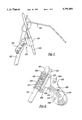
- FIG. 1 is a perspective view of a left side recline latch system for a collapsible stroller
- FIG. 2 is a front view of a right side recline latch system for a collapsible stroller showing the engagement of the slidable member with the plate member;
- FIG. 3 is a top view of the place member of FIG. 2;
- FIG. 4 is a left side view of the plate member of FIG. 3;
- FIG. 5 is a right side view of the plate member of FIG. 3;
- FIG. 6 is a front view of the plate member of FIG. 3;
- FIG. 7 is a bottom view of the plate member of FIG. 3;
- FIG. 8 is a cross sectional view of the plate member along line VIII--VIII of FIG. 3;
- FIG. 9 is a top view of the slidable member of FIG. 2;
- FIG. 10 is a side view of the slidable member from the direction indicated by line X--X of FIG. 9;
- FIG. 11 is a cross-sectional view of the slidable member along line XI--XI of FIG. 9.
- a recline latch unit includes right and left side recline latch systems.
- FIG. 1 shows a perspective view of a preferred left side recline latch system 100 on a collapsible stroller.
- the stroller also includes a frame 102 and a passenger support 104.
- the latch system 100 includes a plate member (or recline plate) 106 and a slidable member (or recline key) 108.
- the recline latch system 100 may include means for actuating the slidable member 108.
- a pull wire 110 actuates the slidable member 108 and a second slidable member (not shown) located on a side of the stroller opposite to that shown in FIG. 1.
- finger tabs can be formed on both slidable members 108 to actuate the recline latch system instead of the pull wire 110.
- FIG. 2 shows the engagement of the slidable member 108 with the plate member 106.
- slidable member 108 is shown in a cross sectional view.
- the plate member 106 is a one piece member having an elongated, flat shape formed of a resilient material such as plastic.
- the plate member 106 includes at least one stop 202 rising from the plate surface 204.
- the preferred embodiment has a plurality of stops 202 so that the inclination of the passenger support 104 can be varied. While the stops 202 may be substantially solid, the stops 202 are preferably structured as a plurality of ribs 205 to facilitate fabrication, to reduce material usage, and to minimize friction between the slidable member 108 and the stop 202.
- Holes 206 are used to connect the plate member 106 to the frame (not shown in FIG. 2) using rivets, nuts and bolts, pins, or the like.
- the slidable member 108 includes an engagement portion 208 extended from the body 210 of the slidable member.
- the engagement portion 208 is brought into contact with the face 212 of stops 202 by gravity or an elastic member acting on the passenger support 104.
- the slidable member 108 is mounted onto the passenger support 104 via a bore 214.
- the slidable member 108 is slidable between a first position and a second position Preferably, the first position corresponds the an engaged position, and the second position corresponds to a disengaged position,
- the range of movement of the slidable member 108 is limited by means such as a slot 216 on the sliding member 108 and a pin 217 mounted on support 104.
- the pin 217 may alternatively be a bolt, a rivet or the like. Pairs of slots 216 are preferably positioned on opposite sides of the slidable member 208.
- a spring 220 is located in the interior of the bore 214 between the body 210 and the passenger support 104 to bias the slidable member 10 toward the first covered position.
- the body 210 also defines a sleeve 218 for connecting the pull wire 110 to the slidable member 108.
- the pull wire 110 is adapted to actuate the slidable member 108 to a second, raised position. In the second position, the engagement portion 208 disengages the stop 202.
- the passenger support 104 can be relocated to other inclinations or to a fully reclined position. When the passenger support 104 is fully reclined, the plate member 106 and the slidable member 108 are separated.
- FIGS. 3 to 7 show the plate member 106 from front, left, right, bottom, and rear views, respectively.
- FIG. 8 is a cross sectional view of the plate member 106 along line VIII--VIII of FIG. 3.
- stops 202 are constructed with ribs. Each stop 202 has a face 212 and sloped portions 302. The sloped portions allow the engagement portion 208 to move easily over the stop as the passenger support 104 is being raised. Consequently, the user does not need to actuate the recline latch system 100 to raise the passenger support 104
- a lead-in portion 304 is positioned at a lower region of the plate member 106. The lead-in portion 304 guides the engagement portion 208 (see FIG.
- gaps 306 provide regions in which the engagement portion 208 of the slidable member 108 is positioned to engage the respective face 212 of the stop 202.
- a catch 308 is provided on the upper end of the plate portion 106 to prevent raising the passenger support 104 too far (i.e., over-stroking). As a result, the engagement member 208 of the slidable member 108 cannot over-stroke the plate member 106.
- the rear of the plate member 106 defines a slot 310 so that the frame 102 securely retains the plate member 106.
- FIG. 9 shows a top view of the slidable member 108
- figure 10 shows the slidable member 108 from the direction as indicated line X--X of FIG. 3
- FIG. 11 shows a cross sectional view of the slidable member 108 along line XI--XI of FIG. 3.
- the slidable member 106 defines a bore 214 which is substantially circular.
- the slidable member 108 also includes a sleeve 218 for receiving and retaining the pull wire 110 which is inserted into sleeve 216 through the opening 902.
- the end of the pull wire 110 includes an L-shaped bend (not shown) which fits through the hole 904 of the sleeve 218, thereby securing the position of the pull wire 110 in the sleeve 218.
- the sleeve 218 includes a support collar 906 around the hole 904 to improve rigidity and strength of the sleeve 218 and to receive the L-shaped bend of the pull wire 110.
- the slots 216 are preferably located on opposite sides of the slidable member 108.
- the engagement member 208 includes an engagement surface 908 to cooperate and engage the face 212 of the plate member 106.
- the engagement portion 208 also includes a catch 910 on the distal end thereof to cooperate with the catch 308 of the plate member 106. In the preferred embodiment, both catches 308 and 910 are substantially hook shaped So that they can mate with each other.
- the user actuates the slidable member 104. Actuation is achieved in the preferred embodiment by pulling the pull wire 110, thereby moving the slidable member 108 up the passenger support 104 from the first position to the second, raised position.
- the spring 220 is compressed.
- the engagement portion 208 is clear of the stops 202 when the slidable member 202 is in the second position.
- the user can move the passenger support 104 to alternate lower inclinations defined by the stops 202 or to the fully reclined position
- the spring 220 will return the slidable member 108 to the first position.
- the user simply lifts the passenger support 104.
- the lead portion 304 guides the engagement portion 208 onto the plate member 106.
- the sloped portions 302 guide the engagement portion 208 over the stops 202.
- the engagement position deflects.
- the slidable member 108 does not need to be actuated by the user during raising of the passenger support 104.
- the engagement portion 208 can engage any desired stop 202 after the engagement portion 208 passes that stop, thereby holding the passenger support 104 in the desired inclination.
- the catches 308 and 910 prevent the engagement portion 208 from passing beyond the upper end of the plate member 106, thereby preventing over-stroking of the engagement portion 208,
- the recline latch system 100 automatically disengages.
- the passenger support 104 moves upward relative to the frame when the stroller frame is folded.
- the engagement portion 208 moves upward with respect to the plate member 106, This allows the engagement portion 203 to clear the stop 202 without the user actuating the slidable member 108 and fall to the lowered, recline position.
- the present invention provides a recline latch system for a collapsible stroller which locks a passenger support in an up position.
- the recline latch system is easily operated with one band when reclining the passenger support or collapsing the stroller.
- recline latch system is less complicated than conventional recline latch systems. Accordingly, the present recline latch system is simpler to manufacture and assemble.
Abstract
A recline latch system for a collapsible stroller having a frame and a reclineable passenger support movable between at least one up position and a down position. The recline latch system includes a plate member connected to the frame for retaining the passenger support in the up position, a slidable member connected to the passenger support, wherein the slidable member is slidable between an engaged position and a disengaged position, and an engagement portion disposed on the slidable member, wherein the engagement portion is adapted to cooperate with the plate member when the slidable member is in the engaged position. The recline latch system preferably provides single-handed operation, multi-positional settings for the passenger support, and automatic disengagement while collapsing of the stroller.
Description
application is a continuation of U.S. patent application Ser. No. 08/738,237, filed Oct. 25, 1996.
1. Field of the Invention
The present invention relates to a collapsible stroller, and more particularly, to a recline latch system for a collapsible stroller.
2. Discussion of the Related Art
Strollers that collapse or fold up provide highly convenient transportability. Consequently, such strollers have been very popular in the market. An example of a collapsible stroller is disclosed in U.S. Pat. No. 5,454,584 to Haut et al., the disclosure of which is incorporated by reference herein.
Such collapsible strollers usually include a frame and a with passenger support. Typically, the passenger support is movable with respect to the frame between an up position and a down position. The up position allows the passenger to be positioned in a seated position, whereas the down position allows the passenger to be in a recumbent position. As is well known in the art, it is usually necessary that the passenger support be in the down position when the user collapses the stroller. By placing the passenger support substantially in the same plan or orientation as the seat, the stroller is collapsed into a compact unit.
Latches are usually used to operate the collapsibility of the stroller. However, conventional latches require many complicated parts. This causes the latches to be bulky, thereby increasing the weight of the stroller. Furthermore, conventional latches are complicated to operate and often require two-handed operation.
Accordingly, the present invention is directed to a recline latch system that substantially obviates one or more of the problems due to limitations and disadvantages of the related art.
An object of the present invention to provide a recline latch system for a collapsible stroller which locks a passenger support in an up position that can be easily disengaged to recline the passenger support or to collapse the stroller.
Another object of the present invention is to provide a recline latch system which operate and cooperates with a stroller frame to allow convenient, ergonomic operation.
An additional object of the present invention is to provide a recline latch system which provides multi-positional settings for a passenger support.
A further object of the present invention is to provide a recline latch system having fewer, less complicated parts.
A still further object of the present invention is to provide a recline latch system which is easily manufactured and assembled at a minimal cost.
Yet another object of the present invention is to provide a recline latch system that can be operated with one hand.
Another object of the present invention is to provide a recline latch system which automatically disengages when the stroller is collapsed.
A further object of the present invention is to provide a recline latch system which reduces weight and bulk.
Additional features and advantages of the invention will be set forth in the description which follows, and in part will be apparent from the description, or may be learned by practice of the invention The objectives and other advantages of the invention will be realized and attained by the structure particularly pointed out in the written description and claims hereof as well as the appended drawings.
To achieve these and other advantages and in accordance with the purpose of the present invention, as embodied and broadly described, the recline latch system for a collapsible stroller having a frame and a reclineable passenger support movable between an up position and a down position, includes a place member connected to the frame for retaining the passenger support in the up position; a slidable member connected to the passenger support, wherein the slidable member is slidable between a first position (preferably an engaged position) and a second position (preferably a disengaged position); and an engagement portion disposed on the slidable member, wherein the engagement portion is adapted to cooperate with the plate member when the slidable member is in the first position.
It is to be understood that both the foregoing general description and the following detailed description are exemplary and explanatory and are intended to provide further explanation of the invention as claimed.
The accompanying drawings, which are included to provide a further understanding of the invention and are incorporated in and constitute a part of this specification, illustrate embodiments of the invention and together with the description serve to explain the principles of the invention. In the drawings,
FIG. 1 is a perspective view of a left side recline latch system for a collapsible stroller;
FIG. 2 is a front view of a right side recline latch system for a collapsible stroller showing the engagement of the slidable member with the plate member;
FIG. 3 is a top view of the place member of FIG. 2;
FIG. 4 is a left side view of the plate member of FIG. 3;
FIG. 5 is a right side view of the plate member of FIG. 3;
FIG. 6 is a front view of the plate member of FIG. 3;
FIG. 7 is a bottom view of the plate member of FIG. 3;
FIG. 8 is a cross sectional view of the plate member along line VIII--VIII of FIG. 3;
FIG. 9 is a top view of the slidable member of FIG. 2;
FIG. 10 is a side view of the slidable member from the direction indicated by line X--X of FIG. 9; and
FIG. 11 is a cross-sectional view of the slidable member along line XI--XI of FIG. 9.
Reference will now be made in detail to the preferred embodiments of the present invention, examples of which are illustrated in the accompanying drawings. Wherever possible, the same reference numbers will be used throughout the drawings to refer to the same or like parts
In accordance with the present invention, a recline latch unit includes right and left side recline latch systems. FIG. 1 shows a perspective view of a preferred left side recline latch system 100 on a collapsible stroller. The stroller also includes a frame 102 and a passenger support 104. Generally, the latch system 100 includes a plate member (or recline plate) 106 and a slidable member (or recline key) 108. The recline latch system 100 may include means for actuating the slidable member 108. In a preferred embodiment, a pull wire 110 actuates the slidable member 108 and a second slidable member (not shown) located on a side of the stroller opposite to that shown in FIG. 1. Alternatively, finger tabs can be formed on both slidable members 108 to actuate the recline latch system instead of the pull wire 110.
FIG. 2 shows the engagement of the slidable member 108 with the plate member 106. Here, slidable member 108 is shown in a cross sectional view. Referring to FIG. 2, the plate member 106 is a one piece member having an elongated, flat shape formed of a resilient material such as plastic. The plate member 106 includes at least one stop 202 rising from the plate surface 204. The preferred embodiment has a plurality of stops 202 so that the inclination of the passenger support 104 can be varied. While the stops 202 may be substantially solid, the stops 202 are preferably structured as a plurality of ribs 205 to facilitate fabrication, to reduce material usage, and to minimize friction between the slidable member 108 and the stop 202. Holes 206 are used to connect the plate member 106 to the frame (not shown in FIG. 2) using rivets, nuts and bolts, pins, or the like.
The slidable member 108 includes an engagement portion 208 extended from the body 210 of the slidable member. The engagement portion 208 is brought into contact with the face 212 of stops 202 by gravity or an elastic member acting on the passenger support 104. The slidable member 108 is mounted onto the passenger support 104 via a bore 214. The slidable member 108 is slidable between a first position and a second position Preferably, the first position corresponds the an engaged position, and the second position corresponds to a disengaged position, The range of movement of the slidable member 108 is limited by means such as a slot 216 on the sliding member 108 and a pin 217 mounted on support 104. The pin 217 may alternatively be a bolt, a rivet or the like. Pairs of slots 216 are preferably positioned on opposite sides of the slidable member 208. A spring 220 is located in the interior of the bore 214 between the body 210 and the passenger support 104 to bias the slidable member 10 toward the first covered position. The body 210 also defines a sleeve 218 for connecting the pull wire 110 to the slidable member 108. The pull wire 110 is adapted to actuate the slidable member 108 to a second, raised position. In the second position, the engagement portion 208 disengages the stop 202. As a result, the passenger support 104 can be relocated to other inclinations or to a fully reclined position. When the passenger support 104 is fully reclined, the plate member 106 and the slidable member 108 are separated.
FIGS. 3 to 7 show the plate member 106 from front, left, right, bottom, and rear views, respectively. FIG. 8 is a cross sectional view of the plate member 106 along line VIII--VIII of FIG. 3. As noted above, stops 202 are constructed with ribs. Each stop 202 has a face 212 and sloped portions 302. The sloped portions allow the engagement portion 208 to move easily over the stop as the passenger support 104 is being raised. Consequently, the user does not need to actuate the recline latch system 100 to raise the passenger support 104 Furthermore, a lead-in portion 304 is positioned at a lower region of the plate member 106. The lead-in portion 304 guides the engagement portion 208 (see FIG. 8) onto the plate member 106 when the passenger support is raised from a fully reclined position. Between each stop 202, gaps 306 provide regions in which the engagement portion 208 of the slidable member 108 is positioned to engage the respective face 212 of the stop 202. A catch 308 is provided on the upper end of the plate portion 106 to prevent raising the passenger support 104 too far (i.e., over-stroking). As a result, the engagement member 208 of the slidable member 108 cannot over-stroke the plate member 106. The rear of the plate member 106 defines a slot 310 so that the frame 102 securely retains the plate member 106.
FIG. 9 shows a top view of the slidable member 108, figure 10 shows the slidable member 108 from the direction as indicated line X--X of FIG. 3, and FIG. 11 shows a cross sectional view of the slidable member 108 along line XI--XI of FIG. 3. As noted above, the slidable member 106 defines a bore 214 which is substantially circular. The slidable member 108 also includes a sleeve 218 for receiving and retaining the pull wire 110 which is inserted into sleeve 216 through the opening 902. The end of the pull wire 110 includes an L-shaped bend (not shown) which fits through the hole 904 of the sleeve 218, thereby securing the position of the pull wire 110 in the sleeve 218. The sleeve 218 includes a support collar 906 around the hole 904 to improve rigidity and strength of the sleeve 218 and to receive the L-shaped bend of the pull wire 110. As noted above, the slots 216 are preferably located on opposite sides of the slidable member 108. The engagement member 208 includes an engagement surface 908 to cooperate and engage the face 212 of the plate member 106. The engagement portion 208 also includes a catch 910 on the distal end thereof to cooperate with the catch 308 of the plate member 106. In the preferred embodiment, both catches 308 and 910 are substantially hook shaped So that they can mate with each other.
The operation of the recline latch system in accordance with the preferred embodiment of the present invention will now be described. To lower the passenger support 104, the user actuates the slidable member 104. Actuation is achieved in the preferred embodiment by pulling the pull wire 110, thereby moving the slidable member 108 up the passenger support 104 from the first position to the second, raised position. When the slidable member 106 is moved to the second position, the spring 220 is compressed. The engagement portion 208 is clear of the stops 202 when the slidable member 202 is in the second position. At this time, the user can move the passenger support 104 to alternate lower inclinations defined by the stops 202 or to the fully reclined position When the user releases the pull wire 110, the spring 220 will return the slidable member 108 to the first position.
To raise the passenger support 104, the user simply lifts the passenger support 104. As the passenger support 104 is lifted to a level where the engagement portion 208 contacts the plate member 106, the lead portion 304 guides the engagement portion 208 onto the plate member 106. Then, as the engagement portion 208 is lifted and encounters the stops 202, the sloped portions 302 guide the engagement portion 208 over the stops 202. During this, the engagement position deflects. As a result, the slidable member 108 does not need to be actuated by the user during raising of the passenger support 104. The engagement portion 208 can engage any desired stop 202 after the engagement portion 208 passes that stop, thereby holding the passenger support 104 in the desired inclination. The catches 308 and 910 prevent the engagement portion 208 from passing beyond the upper end of the plate member 106, thereby preventing over-stroking of the engagement portion 208,
When the user collapses the stroller, the recline latch system 100 automatically disengages. As is known in the art (see, e.g., U.S. Pat. No. 5,454,548 to Haut et al.), the passenger support 104 moves upward relative to the frame when the stroller frame is folded. As a result, the engagement portion 208 moves upward with respect to the plate member 106, This allows the engagement portion 203 to clear the stop 202 without the user actuating the slidable member 108 and fall to the lowered, recline position.
The present invention provides a recline latch system for a collapsible stroller which locks a passenger support in an up position. The recline latch system is easily operated with one band when reclining the passenger support or collapsing the stroller. In addition, recline latch system is less complicated than conventional recline latch systems. Accordingly, the present recline latch system is simpler to manufacture and assemble.
It will be apparent to those skilled in the art that various modifications and variations can be made in the recline latch of the present invention without departing from the spirit or scope of the invention. Thus, it is intended that the present invention cover the modifications and variations of this invention provided they come within the scope of the appended claims and their equivalents.
Claims (18)
1. A stroller, said stroller having a frame and a reclinable passenger support movable between at least one up position and a down position, the stroller comprising:
a plate member connected to the frame for retaining the reclinable passenger support in the up position, said plate member including a plurality of stops, each stop having a face portion and a sloped portion including a plurality of ribs perpendicularly disposed relative to said face portion;
a slidable member connected to the reclinable passenger support, wherein the slidable member is slidable between a first position and a second position; and an engagement portion disposed on the slidable member, wherein the engagement portion is adapted to cooperate with the plate member when the slidable member is in the first position.
2. The stroller according to claim 1, wherein the plate member includes a plurality of stops for cooperating with the engagement portion, the plurality of stops corresponding to a plurality of up positions of the passenger support.
3. The stroller according to claim 1, wherein the plate member includes at least one stop for cooperating with the engagement portion.
4. The stroller according to claim 3, wherein the stop includes a sloped portion for guiding the engagement portion over each stop.
5. The stroller according to claim 4, wherein each stop includes a face portion for retaining the engagement portion.
6. The stroller according to claim 1, wherein the plate member includes an over-stroke catch to retain the engagement member.
7. The stroller according to claim 1, therein the plate member includes a first over-stroke catch, and wherein the slidable member includes a second over-stroke catch, the first and second over-stroke catches cooperating to retain the engagement portion from sliding beyond an upper end of the plate member.
8. The stroller according to claim 1, wherein the second position of the slidable member disengages the engagement portion with the plate member.
9. The stroller according to claim 1, wherein the slidable member includes a spring to bias the slidable member in the first position.
10. The stroller according to claim 1, further comprising a pin which protrudes from the reclinable passenger support, wherein the slidable member defines a slot which cooperates with the pin to limit the movement of the slidable member.
11. The stroller according to claim 1, further comprising an actuation member for actuating the slidable member.
12. The stroller according to claim 11, wherein the actuation member includes a pull wire.
13. A stroller having a frame and a reclinable passenger support movable between a plurality of up positions, the reclinable passenger support having a pivot point such that said reclinable passenger support is pivotable, the stroller comprising:
a plate member connected to the frame for retaining the passenger support in each position of said up positions, said plate member including a plurality of stops, each stop being arcuately disposed on said plate member, said arc having a focal point corresponding to the pivot point of said reclinable passenger support, each stop includes a plurality of ribs on said sloped portion and perpendicularly disposed relative to each face portion;
a slidable member connected to the passenger support, wherein the slidable member is slidable between a first position and a second position; and
an engagement portion disposed on the slidable member, wherein the engagement portion engages with the plate member when the slidable member is in the first position.
14. The stroller according to claim 13, wherein the plate member includes a plurality of stops for cooperating with the engagement portion, the plurality of stops corresponding to a plurality of up positions of the reclinable passenger support.
15. The stroller according to claim 13, wherein each stop includes a face portion for restraining the engagement portion.
16. The stroller according to claim 15, wherein each stop includes a sloped portion for guiding the engagement portion over the stop.
17. The stroller according to claim 13, wherein the second position of the slidable member disengages the engagement portion with the plate member.
18. The stroller according to claim 13, wherein the plate member includes a first over-stroke catch, and wherein the slidable member includes a second over-stroke catch, the first and second over-stroke catches cooperating to retain the engagement portion from sliding beyond an upper end of the plate member.
Priority Applications (1)
| Application Number | Priority Date | Filing Date | Title |
|---|---|---|---|
| US08/806,426 US5795091A (en) | 1996-10-25 | 1997-02-26 | Recline latch system for collapsible stroller |
Applications Claiming Priority (2)
| Application Number | Priority Date | Filing Date | Title |
|---|---|---|---|
| US73823796A | 1996-10-25 | 1996-10-25 | |
| US08/806,426 US5795091A (en) | 1996-10-25 | 1997-02-26 | Recline latch system for collapsible stroller |
Related Parent Applications (1)
| Application Number | Title | Priority Date | Filing Date |
|---|---|---|---|
| US73823796A Continuation | 1996-10-25 | 1996-10-25 |
Publications (1)
| Publication Number | Publication Date |
|---|---|
| US5795091A true US5795091A (en) | 1998-08-18 |
Family
ID=24967157
Family Applications (1)
| Application Number | Title | Priority Date | Filing Date |
|---|---|---|---|
| US08/806,426 Expired - Lifetime US5795091A (en) | 1996-10-25 | 1997-02-26 | Recline latch system for collapsible stroller |
Country Status (1)
| Country | Link |
|---|---|
| US (1) | US5795091A (en) |
Cited By (14)
| Publication number | Priority date | Publication date | Assignee | Title |
|---|---|---|---|---|
| WO2002028227A2 (en) * | 2000-10-04 | 2002-04-11 | Northpole, Ltd. | Collapsible chair with resilient support elements |
| US20030080536A1 (en) * | 2000-05-08 | 2003-05-01 | Graco Children's Products Inc. | Foldable stroller |
| US20040094935A1 (en) * | 2002-11-19 | 2004-05-20 | Paul Fair | Tandem stroller with side entry and associated fold actuator |
| US20060214486A1 (en) * | 2005-03-15 | 2006-09-28 | Graco Children's Products Inc. | Child swing with recline mechanism |
| US20070273191A1 (en) * | 2006-05-26 | 2007-11-29 | Wonderland Nurserygoods Co., Ltd. | Angle-adjustable backrest device for a child highchair |
| US20100044164A1 (en) * | 2007-02-19 | 2010-02-25 | Thorley Industries, Llc | Braking System for a Stroller |
| US7686322B2 (en) | 2004-04-30 | 2010-03-30 | Chicco Usa, Inc. | Foldable stroller with memory recline |
| USD636300S1 (en) | 2009-08-14 | 2011-04-19 | Artsana Usa, Inc. | Stroller |
| USD651140S1 (en) | 2010-12-20 | 2011-12-27 | Artsana Usa, Inc. | Stroller frame tubing |
| US8100429B2 (en) | 2008-03-31 | 2012-01-24 | Artsana Usa, Inc. | Three dimensional folding stroller with infant carrier attachment and one hand actuated seat recline |
| US8186705B2 (en) | 2008-08-15 | 2012-05-29 | Artsana Usa, Inc. | Stroller |
| US8240700B2 (en) | 2008-08-15 | 2012-08-14 | Artsana Usa, Inc. | Stroller with travel seat attachment |
| US8262124B2 (en) | 2007-11-01 | 2012-09-11 | Artsana Usa, Inc. | Folding stroller actuating system |
| US9399477B2 (en) | 2012-12-27 | 2016-07-26 | Kolcraft Enterprises, Inc. | Strollers with removable child supports and related methods |
Citations (34)
| Publication number | Priority date | Publication date | Assignee | Title |
|---|---|---|---|---|
| US2783053A (en) * | 1956-02-15 | 1957-02-26 | Collier Keyworth Company | Collapsible stroller |
| US2966365A (en) * | 1958-12-08 | 1960-12-27 | Atlas Tool & Mfg Co | Lawn mower handle |
| US3277601A (en) * | 1964-01-23 | 1966-10-11 | John W Ryan | Doll having an angularly adjustable limb |
| US3533648A (en) * | 1967-09-14 | 1970-10-13 | Arthur M Thieberger | Support for a lamp |
| US4415180A (en) * | 1981-04-27 | 1983-11-15 | Dawn Designs, Inc. | Stroller latch |
| US4433869A (en) * | 1980-12-15 | 1984-02-28 | Dawn Designs, Inc. | Baby walker |
| GB2076300B (en) * | 1980-05-23 | 1984-04-18 | Graco Metal Products Inc | Infant swing carrier |
| US4632421A (en) * | 1986-02-19 | 1986-12-30 | Louis Shamie | Folding baby carriage with double lock |
| US4660850A (en) * | 1984-10-12 | 1987-04-28 | Combi Co., Ltd. | Baby stroller |
| US4736959A (en) * | 1986-02-05 | 1988-04-12 | Amatech Corporation | Convertible carriage |
| US4805928A (en) * | 1986-07-23 | 1989-02-21 | Combi Co., Ltd. | Reclining mechanism of baby carriage |
| US4809724A (en) * | 1987-03-24 | 1989-03-07 | Anacleto Fuser | Sunshade-holder for deck chairs and baby carriages |
| US4858947A (en) * | 1987-10-26 | 1989-08-22 | A B Oriental Trading Co., Inc. | Folding tandem seat baby carriage |
| US4886289A (en) * | 1987-10-26 | 1989-12-12 | A B Oriental Trading Company, Inc. | Tandem baby carriage with facing seats |
| US4907818A (en) * | 1987-08-31 | 1990-03-13 | Chai Mong H | Safety device to prevent baby carriages from being accidentally folded |
| US5018754A (en) * | 1990-03-07 | 1991-05-28 | Joanna A. Nichols | Front seat reversing structure for dual-seat baby stroller |
| US5039118A (en) * | 1990-08-22 | 1991-08-13 | Huang Ming Tai | Stroller with an improved connector |
| US5056805A (en) * | 1990-06-05 | 1991-10-15 | Wang Chia Ho | Stroller |
| US5062179A (en) * | 1991-03-11 | 1991-11-05 | Huang Ming Tai | Handle assembly for doll carriages |
| US5087066A (en) * | 1989-02-16 | 1992-02-11 | Baby Trend, Inc. | Foldable baby stroller |
| US5143398A (en) * | 1991-07-03 | 1992-09-01 | Teng Jerry M S | Collapsible structure for a stroller |
| US5167425A (en) * | 1991-04-23 | 1992-12-01 | Chen Shih Shyan | Means for use in reversing front seat of a multi-seat stroller |
| US5168601A (en) * | 1992-07-21 | 1992-12-08 | Liu Kun Hei | Adjustable baby cart handrail positioning device |
| US5184835A (en) * | 1992-04-21 | 1993-02-09 | Taiwan Charwell Enterprise Co., Ltd. | Handle height adjuster for baby carriage |
| US5190390A (en) * | 1992-01-08 | 1993-03-02 | Ming Tai Huang | Joint for connecting a canopy support to a stroller |
| US5201333A (en) * | 1991-09-10 | 1993-04-13 | Lumex, Inc. | Folding walker |
| US5205577A (en) * | 1992-07-21 | 1993-04-27 | Liu Kun Hei | Collapsible folding baby cart collapse control mechanism |
| US5221106A (en) * | 1992-04-23 | 1993-06-22 | Louis Shamie | Tandem seat umbrella stroller |
| US5244228A (en) * | 1992-02-08 | 1993-09-14 | Sunshon Molding Co., Ltd. | Collapsible device for a baby carriage |
| US5257799A (en) * | 1991-10-04 | 1993-11-02 | Cosco, Inc. | Foldable stroller |
| US5454584A (en) * | 1993-04-20 | 1995-10-03 | Graco Children's Products, Inc. | Collapsable stroller |
| US5482311A (en) * | 1994-09-02 | 1996-01-09 | Huang; Li-Chu C. | Adjusting/positioning device for a backrest of a stroller |
| US5516142A (en) * | 1993-09-17 | 1996-05-14 | J. G. Hartan Kinderwagenwerk | Buggy with a collapsible frame |
| US5622377A (en) * | 1995-06-06 | 1997-04-22 | Shamie; Louis | Stroller with folding mechanism for folding stroller entirely while upright |
-
1997
- 1997-02-26 US US08/806,426 patent/US5795091A/en not_active Expired - Lifetime
Patent Citations (35)
| Publication number | Priority date | Publication date | Assignee | Title |
|---|---|---|---|---|
| US2783053A (en) * | 1956-02-15 | 1957-02-26 | Collier Keyworth Company | Collapsible stroller |
| US2966365A (en) * | 1958-12-08 | 1960-12-27 | Atlas Tool & Mfg Co | Lawn mower handle |
| US3277601A (en) * | 1964-01-23 | 1966-10-11 | John W Ryan | Doll having an angularly adjustable limb |
| US3533648A (en) * | 1967-09-14 | 1970-10-13 | Arthur M Thieberger | Support for a lamp |
| GB2076300B (en) * | 1980-05-23 | 1984-04-18 | Graco Metal Products Inc | Infant swing carrier |
| US4433869A (en) * | 1980-12-15 | 1984-02-28 | Dawn Designs, Inc. | Baby walker |
| US4415180A (en) * | 1981-04-27 | 1983-11-15 | Dawn Designs, Inc. | Stroller latch |
| US4660850A (en) * | 1984-10-12 | 1987-04-28 | Combi Co., Ltd. | Baby stroller |
| US4736959A (en) * | 1986-02-05 | 1988-04-12 | Amatech Corporation | Convertible carriage |
| US4632421A (en) * | 1986-02-19 | 1986-12-30 | Louis Shamie | Folding baby carriage with double lock |
| US4805928A (en) * | 1986-07-23 | 1989-02-21 | Combi Co., Ltd. | Reclining mechanism of baby carriage |
| US4809724A (en) * | 1987-03-24 | 1989-03-07 | Anacleto Fuser | Sunshade-holder for deck chairs and baby carriages |
| US4907818A (en) * | 1987-08-31 | 1990-03-13 | Chai Mong H | Safety device to prevent baby carriages from being accidentally folded |
| US4858947A (en) * | 1987-10-26 | 1989-08-22 | A B Oriental Trading Co., Inc. | Folding tandem seat baby carriage |
| US4886289A (en) * | 1987-10-26 | 1989-12-12 | A B Oriental Trading Company, Inc. | Tandem baby carriage with facing seats |
| US5087066A (en) * | 1989-02-16 | 1992-02-11 | Baby Trend, Inc. | Foldable baby stroller |
| US5018754A (en) * | 1990-03-07 | 1991-05-28 | Joanna A. Nichols | Front seat reversing structure for dual-seat baby stroller |
| US5056805A (en) * | 1990-06-05 | 1991-10-15 | Wang Chia Ho | Stroller |
| US5039118A (en) * | 1990-08-22 | 1991-08-13 | Huang Ming Tai | Stroller with an improved connector |
| US5062179A (en) * | 1991-03-11 | 1991-11-05 | Huang Ming Tai | Handle assembly for doll carriages |
| US5167425A (en) * | 1991-04-23 | 1992-12-01 | Chen Shih Shyan | Means for use in reversing front seat of a multi-seat stroller |
| US5143398A (en) * | 1991-07-03 | 1992-09-01 | Teng Jerry M S | Collapsible structure for a stroller |
| US5201333A (en) * | 1991-09-10 | 1993-04-13 | Lumex, Inc. | Folding walker |
| US5257799A (en) * | 1991-10-04 | 1993-11-02 | Cosco, Inc. | Foldable stroller |
| US5190390A (en) * | 1992-01-08 | 1993-03-02 | Ming Tai Huang | Joint for connecting a canopy support to a stroller |
| US5244228A (en) * | 1992-02-08 | 1993-09-14 | Sunshon Molding Co., Ltd. | Collapsible device for a baby carriage |
| US5184835A (en) * | 1992-04-21 | 1993-02-09 | Taiwan Charwell Enterprise Co., Ltd. | Handle height adjuster for baby carriage |
| US5221106A (en) * | 1992-04-23 | 1993-06-22 | Louis Shamie | Tandem seat umbrella stroller |
| US5205577A (en) * | 1992-07-21 | 1993-04-27 | Liu Kun Hei | Collapsible folding baby cart collapse control mechanism |
| US5168601A (en) * | 1992-07-21 | 1992-12-08 | Liu Kun Hei | Adjustable baby cart handrail positioning device |
| US5454584A (en) * | 1993-04-20 | 1995-10-03 | Graco Children's Products, Inc. | Collapsable stroller |
| US5605409A (en) * | 1993-04-20 | 1997-02-25 | Graco Children's Products, Inc. | Collapsible stroller |
| US5516142A (en) * | 1993-09-17 | 1996-05-14 | J. G. Hartan Kinderwagenwerk | Buggy with a collapsible frame |
| US5482311A (en) * | 1994-09-02 | 1996-01-09 | Huang; Li-Chu C. | Adjusting/positioning device for a backrest of a stroller |
| US5622377A (en) * | 1995-06-06 | 1997-04-22 | Shamie; Louis | Stroller with folding mechanism for folding stroller entirely while upright |
Cited By (25)
| Publication number | Priority date | Publication date | Assignee | Title |
|---|---|---|---|---|
| US20030080536A1 (en) * | 2000-05-08 | 2003-05-01 | Graco Children's Products Inc. | Foldable stroller |
| US7044497B2 (en) * | 2000-05-08 | 2006-05-16 | Graco Children's Products Inc. | Foldable stroller |
| WO2002028227A3 (en) * | 2000-10-04 | 2002-06-27 | Northpole Ltd | Collapsible chair with resilient support elements |
| WO2002028227A2 (en) * | 2000-10-04 | 2002-04-11 | Northpole, Ltd. | Collapsible chair with resilient support elements |
| US20040094935A1 (en) * | 2002-11-19 | 2004-05-20 | Paul Fair | Tandem stroller with side entry and associated fold actuator |
| US6935652B2 (en) | 2002-11-19 | 2005-08-30 | Evenflo Company, Inc. | Tandem stroller with side entry and associated fold actuator |
| US7686322B2 (en) | 2004-04-30 | 2010-03-30 | Chicco Usa, Inc. | Foldable stroller with memory recline |
| US20060214486A1 (en) * | 2005-03-15 | 2006-09-28 | Graco Children's Products Inc. | Child swing with recline mechanism |
| US7219959B2 (en) | 2005-03-15 | 2007-05-22 | Graco Children's Products Inc. | Child swing with recline mechanism |
| US20070273191A1 (en) * | 2006-05-26 | 2007-11-29 | Wonderland Nurserygoods Co., Ltd. | Angle-adjustable backrest device for a child highchair |
| US7441835B2 (en) * | 2006-05-26 | 2008-10-28 | Wonderland Nurserygoods Co., Ltd. | Angle-adjustable backrest device for a child highchair |
| US20100044164A1 (en) * | 2007-02-19 | 2010-02-25 | Thorley Industries, Llc | Braking System for a Stroller |
| US8499898B2 (en) | 2007-02-19 | 2013-08-06 | Thorley Industries Llc | Braking system for a stroller |
| US8500152B2 (en) | 2007-02-19 | 2013-08-06 | Thorley Industries Llc | Collapsible stroller |
| US8193650B2 (en) | 2007-02-19 | 2012-06-05 | Thorley Industries Llc | Power generation system for a stroller |
| US8215808B2 (en) | 2007-02-19 | 2012-07-10 | Thorley Industries Llc | Lighting system for a stroller |
| US8262124B2 (en) | 2007-11-01 | 2012-09-11 | Artsana Usa, Inc. | Folding stroller actuating system |
| US8100429B2 (en) | 2008-03-31 | 2012-01-24 | Artsana Usa, Inc. | Three dimensional folding stroller with infant carrier attachment and one hand actuated seat recline |
| US8382127B2 (en) | 2008-03-31 | 2013-02-26 | Artsana Usa, Inc. | Reclinable seatback support for stroller |
| US8240700B2 (en) | 2008-08-15 | 2012-08-14 | Artsana Usa, Inc. | Stroller with travel seat attachment |
| US8186705B2 (en) | 2008-08-15 | 2012-05-29 | Artsana Usa, Inc. | Stroller |
| US8733785B2 (en) | 2008-09-05 | 2014-05-27 | Thorley Industries Llc | Collapsible stroller |
| USD636300S1 (en) | 2009-08-14 | 2011-04-19 | Artsana Usa, Inc. | Stroller |
| USD651140S1 (en) | 2010-12-20 | 2011-12-27 | Artsana Usa, Inc. | Stroller frame tubing |
| US9399477B2 (en) | 2012-12-27 | 2016-07-26 | Kolcraft Enterprises, Inc. | Strollers with removable child supports and related methods |
Similar Documents
| Publication | Publication Date | Title |
|---|---|---|
| US5795091A (en) | Recline latch system for collapsible stroller | |
| US6155740A (en) | Stroller and a fold latch assembly thereof | |
| US7029064B2 (en) | Collapsible high chair for children | |
| US4660850A (en) | Baby stroller | |
| US7735911B2 (en) | Collapsible high chair for children | |
| US5979928A (en) | Collapsing device for a stroller | |
| EP0595096B1 (en) | Locking/unlocking manipulation mechanism disposed on the handlebars of baby carriage | |
| EP0901953B1 (en) | Infant carrier mounting system | |
| US5947555A (en) | Infant seat and stroller coupling system | |
| US8210563B2 (en) | Reversible stroller handle | |
| US4111454A (en) | Folding baby carriage | |
| EP1953033B1 (en) | Child seat base | |
| US6202229B1 (en) | Joint of a foldable bed for babies | |
| US6557885B1 (en) | Stroller with release latch | |
| JPS59106366A (en) | Baby car | |
| US6120041A (en) | Convertible child care device | |
| EP0256495A2 (en) | Guard attachement/removal structure in baby carriage | |
| US20030229968A1 (en) | Playyard latch mechanism | |
| GB2301621A (en) | Window or like stay | |
| WO2005054001A1 (en) | One-hand fold handle for infant carrier | |
| US6824162B2 (en) | Backrest structure for strollers | |
| US20230278471A1 (en) | Infant car seat and stability leg and release actuator | |
| US5609392A (en) | Integrated child seat | |
| US7635159B2 (en) | Collapsing device and child seat using the same | |
| US5330253A (en) | Mechanism for modulating height of legs of chair for small child |
Legal Events
| Date | Code | Title | Description |
|---|---|---|---|
| AS | Assignment |
Owner name: GRACO CHILDREN'S PRODUCTS, INC., PENNSYLVANIA Free format text: ASSIGNMENT OF ASSIGNORS INTEREST;ASSIGNORS:KAKUDA, BAKU;SACK, JAMES A.;REEL/FRAME:008407/0829 Effective date: 19970219 |
|
| STCF | Information on status: patent grant |
Free format text: PATENTED CASE |
|
| FPAY | Fee payment |
Year of fee payment: 4 |
|
| FPAY | Fee payment |
Year of fee payment: 8 |
|
| FPAY | Fee payment |
Year of fee payment: 12 |