US5808283A - Modular point-of-sale transaction apparatus and method of manufacture and assembly - Google Patents
Modular point-of-sale transaction apparatus and method of manufacture and assembly Download PDFInfo
- Publication number
- US5808283A US5808283A US08/698,885 US69888596A US5808283A US 5808283 A US5808283 A US 5808283A US 69888596 A US69888596 A US 69888596A US 5808283 A US5808283 A US 5808283A
- Authority
- US
- United States
- Prior art keywords
- printer
- module
- transaction terminal
- terminal
- base module
- Prior art date
- Legal status (The legal status is an assumption and is not a legal conclusion. Google has not performed a legal analysis and makes no representation as to the accuracy of the status listed.)
- Expired - Lifetime
Links
Images


Classifications
-
- B—PERFORMING OPERATIONS; TRANSPORTING
- B41—PRINTING; LINING MACHINES; TYPEWRITERS; STAMPS
- B41J—TYPEWRITERS; SELECTIVE PRINTING MECHANISMS, i.e. MECHANISMS PRINTING OTHERWISE THAN FROM A FORME; CORRECTION OF TYPOGRAPHICAL ERRORS
- B41J3/00—Typewriters or selective printing or marking mechanisms characterised by the purpose for which they are constructed
- B41J3/44—Typewriters or selective printing mechanisms having dual functions or combined with, or coupled to, apparatus performing other functions
- B41J3/46—Printing mechanisms combined with apparatus providing a visual indication
-
- B—PERFORMING OPERATIONS; TRANSPORTING
- B41—PRINTING; LINING MACHINES; TYPEWRITERS; STAMPS
- B41J—TYPEWRITERS; SELECTIVE PRINTING MECHANISMS, i.e. MECHANISMS PRINTING OTHERWISE THAN FROM A FORME; CORRECTION OF TYPOGRAPHICAL ERRORS
- B41J29/00—Details of, or accessories for, typewriters or selective printing mechanisms not otherwise provided for
- B41J29/02—Framework
-
- B—PERFORMING OPERATIONS; TRANSPORTING
- B41—PRINTING; LINING MACHINES; TYPEWRITERS; STAMPS
- B41J—TYPEWRITERS; SELECTIVE PRINTING MECHANISMS, i.e. MECHANISMS PRINTING OTHERWISE THAN FROM A FORME; CORRECTION OF TYPOGRAPHICAL ERRORS
- B41J3/00—Typewriters or selective printing or marking mechanisms characterised by the purpose for which they are constructed
- B41J3/36—Typewriters or selective printing or marking mechanisms characterised by the purpose for which they are constructed for portability, i.e. hand-held printers or laptop printers
-
- B—PERFORMING OPERATIONS; TRANSPORTING
- B41—PRINTING; LINING MACHINES; TYPEWRITERS; STAMPS
- B41J—TYPEWRITERS; SELECTIVE PRINTING MECHANISMS, i.e. MECHANISMS PRINTING OTHERWISE THAN FROM A FORME; CORRECTION OF TYPOGRAPHICAL ERRORS
- B41J3/00—Typewriters or selective printing or marking mechanisms characterised by the purpose for which they are constructed
- B41J3/407—Typewriters or selective printing or marking mechanisms characterised by the purpose for which they are constructed for marking on special material
Definitions
- This invention relate in general to modular point-of-sale transaction terminal systems and in particular to point-of-sale transaction terminal system in which various separate modules, such a transaction terminal and printer modules are mounted on a base unit.
- VeriFone Inc. provided a stand for a transaction terminal and a telephone unit to hold the two separate modules in side by side relationship.
- None of these designs and systems provides a simple and facile approach to assembling a transaction terminal and a printer module into an overall system that has substantially the appearance of a completely integrated system, i.e. one in which the various modules seem to be all part of one unit inside a single housing.
- One aspect of this invention features a modular point-of-sale transaction apparatus comprising a modular portion having a printer mechanism mounted within a housing thereof and having structural means providing a terminal platform for supporting a traction terminal in a prearranged position forward or rearward of the printer mechanism.
- the housing for the printer and the platform for supporting the transaction terminal being formed in size and shape and location such that the combination of the modular portion and the transaction terminal has substantially the appearance of a single integrated terminal and printer apparatus.
- One aspect of this invention features a modular point-of-sale transaction apparatus comprising a modular portion having a printer mechanism mounted within a housing thereof and having structural means providing a terminal platform for supporting a transaction terminal in a prearranged position forward or rearward of the printer mechanism.
- the housing for the printer and the platform for supporting the transaction terminal being formed in size and shape and location such that the combination of the modular portion and the transaction terminal has substantially the appearance of a single integrated terminal and printer apparatus.
- the modular portion comprises the combination of a base module and a separate printer module mounted on a printer mounting portion provided on a rearward portion of the base module.
- the terminal platform is defined on the base module at a prearranged forward portion thereof and is adapted to mount a transaction terminal thereon in a position such that a back wall portion of the transaction terminal is adjacent to a front wall portion of the printer module.
- the printer module is adapted to be used with a transaction terminal which has power and data connectors mounted on a rearward facing wall thereof.
- the printer module has a housing with a recessed forward wall portion adapted to cover the power and data connector means when forward wall portion adapted to cover the power and data connector means when both the printer module and the transaction terminal are mounted on the base module.
- the terminal platform is secured on the terminal platform of the base unit using cooperating securing structures formed on a top wall surface of the terminal platform and cooperating with associated securing structures defined on a bottom wall surface of the transaction terminal.
- the printer mounting portion of the base module and bottom wall portions of the housing of the printer module cooperatively provide a slide-on mounting relationship between the base module and the printer module, including a cooperative detent and groove for securing the printer module on the printer mounting portion of the base module.
- the printer module is adapted to be used with a transaction terminal adapted to have power and data connector means mounted on a rearward facing wall thereof, and the printer module has a housing with a recessed forward wall portion adapted to cover the power and data connector means when both the printer module and the transaction terminal are mounted on the base module.
- the printer mounting portion of the base module comprises an open frame section having cable races defined thereon and adapted for receiving cables of the power and data connectors for the transaction terminal to route the cables underneath the printer module and through a back wall portion of the base module.
- the terminal platform has a first securing structure formed on a top wall surface thereof and adapted for cooperating with associated second securing structure defined on a bottom wall surface of the transaction terminal to secure the transaction terminal on the terminal platform.
- the printer mounting portion of the base module and bottom wall portions of the housing of the printer module cooperatively provide a slide-on mounting relationship between the base module and the printer module, including cooperative detent and groove means for securing the printer module on the printer mounting portion of the base module.
- the apparatus is adapted to be assembled with a transaction terminal by first mounting and securing the transaction terminal on the terminal platform using the securing arrangements on platform and terminal, then attaching the power and data connector means to the terminal at a rear wall portion thereof and placing the cables of the power and data connector means in the cable races defined on the open frame section, followed by sliding the printer module onto the printer mounting portion of the base module until the cooperative detent and groove means engage and the recessed forward wall portion of the printer module covers the power and data connector means previously attached to the rear wall portion of the terminal.
- this invention features a modular point-of-sale transaction apparatus comprising a base module, a printer module mounted on the base module, and a transaction terminal mounted on the base module.
- the base module has structural means providing a terminal platform for supporting a transaction terminal in a prearranged position forward or rearward of the printer module.
- the printer module has a housing of prearranged size and shape and the terminal platform is formed in size and shape and location such that the combination of the base module, the transaction terminal and the printer module has substantially the appearance of a single integrated terminal and printer apparatus.
- this invention features a method of assembling a modular point-of-sale transaction apparatus using an existing type of transaction terminal of particular design and shape and having rear wall power and data connectors.
- the method involves forming a base module with a transaction terminal mounting platform on a forward portion thereof and a printer mounting section on a rearward portion thereof with the terminal mounting platform having size and shape such that it accommodates the shape of the transaction terminal.
- Another step of the method is forming a printer module adapted to mount on the base module and having a size and shape adapted to integrate wall with the size and shape of the transaction terminal, including a forward wall section adapted to receive and cover the power and data connectors of the transaction terminal.
- the transaction terminal is then mounted on the terminal platform of the base module, the power and data connectors are mounted to the rear wall of the terminal; and finally the printer module is mounted on the printer mounting portion of the base module with the forward wall section thereof covering the power and data connectors.
- Using the apparatus and method of this invention provides a way to easily integrate separate modules into a convenient unit that has the appearance and functionality of an integrated terminal and printer unit.
- Existing terminal devices can be retrofitted into the assembly of this invention to achieve a much more compact and operationally integrated transaction terminal system.
- FIG. 1A is a pictorial view of a modular point-of-sale transaction apparatus in accordance with this invention with modules fully assembled for operation.
- FIG. 1B is pictorial view from a different viewpoint of a modular point-of-sale transaction apparatus in accordance with this invention with modules fully assembled for operation.
- FIG. 2 is an exploded assembly view of the modules and accessories of a modular point-of-sale transaction apparatus in accordance with this invention.
- FIG. 3 is a pictorial view of a partially assembled modular point-of-sale transaction apparatus in accordance with this invention.
- FIG. 4 is an exploded view illustrating the mounting of a transaction terminal module on a base module to form a portion of a modular point-of-sale transaction apparatus in accordance with this invention.
- FIG. 4A is a perspective view illustrating mounting holes on the bottom of a transaction terminal module useful in explaining the mounting arrangement shown in FIG. 4.
- FIG. 5 is a pictorial view illustrating the connection of cables to a transaction terminal module after mounting of the terminal on a base module to form a portion of a modular point-of-sale transaction apparatus in accordance with this invention.
- FIG. 6 is a pictorial view illustrating mounting of a printer module on a base module after a terminal module and cable connections thereto have been completed.
- FIG. 7 is a pictorial view illustrating one approach to providing operating cable connections to a transaction terminal module and printer module of a modular point-of-sale transaction apparatus in accordance with this invention.
- FIG. 8 is a pictorial view illustrating an alternative approach to providing operating cable connections to a transaction terminal module and printer module of a modular point-of-sale transaction apparatus in accordance with this invention.
- FIG. 9 is a pictorial view illustrating an optional connection of a bar code wand or a PIN-Pad module to one of the ports of a transaction terminal module in a modular point-of-sale transaction apparatus in accordance with this invention.
- FIG. 10 is a perspective view of a base module of a modular point-of-sale transaction apparatus in accordance with this invention.
- FIG. 11 is a side elevational view of a base module of a modular point-of-sale transaction apparatus in accordance with this invention.
- FIG. 12 is a back elevational view of a base module of a modular point-of-sale transaction apparatus in accordance with this invention with a cutaway portion to illustrate one feature thereof.
- FIG. 13 is an exploded assembly drawing illustrating the use of two separately molded pieces to form a base module of a modular point-of-sale transaction apparatus in accordance with this invention.
- FIG. 13A is a partial section view taken along the lines A--A in FIG. 13 and illustrating features of a base module of a modular point-of-sale transaction apparatus in accordance with this invention.
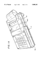
- FIG. 14 is a perspective view of a printer module of a modular point-of-sale transaction apparatus in accordance with this invention.
- FIG. 15 is a side elevational view of a printer module of a modular point-of-sale transaction apparatus in accordance with this invention.
- FIG. 16 is a back elevational view of a printer module of a modular point-of-sale transaction apparatus in accordance with this invention.
- FIG. 17A and FIG. 17B illustrate alternative approaches to providing a modular point-of-sale transaction apparatus in accordance with this invention.
- FIG. 18 is a side view illustrating details of an alternative embodiment of a modular point-of-sale transaction apparatus in accordance with this invention.
- a modular point-of-sale transaction apparatus in accordance with a one embodiment of this invention comprises a base module 10, a printer module 20, and a transaction terminal module 30.
- Base module 10 provides a mounting and support arrangement for both printer module 20 and transaction terminal module 30.
- FIGS. 1A and 1B illustrate, this embodiment of a modular point-of-sale transaction apparatus provides the look and feel of an integral terminal and printer unit when the three modules are assembled together.
- Base module 10 and printer module 20 are specially constructed and arranged to accommodate the cabling required.
- Power supply 41 in the embodiment of FIG. 2 provides operating electrical power to both printer module 20 and transaction terminal module 30.
- Plug 42 is insertable in a standard electrical outlet and male connectors 43 and 44 are insertable into female receptacles provided on the printer module 20 and transaction terminal module 30 in a manner shown in FIG. 7 and described in more detail later.
- a standard telephone cord 45 provides telephone connection for transaction terminal module 30 to a telephone jack hooked to a public switched telephone network.
- Cable 46 is a serial port to serial port connector cable to couple data signals between transaction terminal module 30 and printer module 20. The use of these cables and ports is described in more detail below.
- Transaction terminal module 30 may comprise one of several models of transaction terminals commercially available from VeriFone, Inc. of Redwood City, Calif., namely those models which have the same footprint.
- FIGS. 1A and 1B illustrate use of a TRANZ 330 model of VeriFone transaction terminal. Any of the ZON XL, TRANZ 3xx, and OMNI 3xx models of terminals may also be deployed on base module 10.
- FIG. 4 illustrates an arrangement for mounting transaction terminal module 30 on base module 10.
- Base module 10 has a terminal mounting platform 11 on a forward portion thereof and a printer mounting portion 12 on a rearward portion of base module 10.
- Terminal mounting platform 11 comprises a flat mounting surface 13 with lips 14A-14C on the sides thereof together with an arrangement of three mounting posts 15 carried on mounting surface 12.
- Transaction terminal 30 has a lower base portion 35 with a smaller length and width and this lower base portion is received in the recess formed by side lips 14A-14C of terminal platform 11.
- Mounting posts 15 are received in three keyhole shaped insert and slide type mounting elements 73 which are molded into a bottom wall 31 of transaction terminal module 30.
- Transaction terminal module 30 is then pushed forward to capture it in secure fashion on mounting surface 12.
- the front wall 31 and the side walls 33 and 34 of transaction terminal module 30 are aligned with the corresponding exterior walls of lips 14A-14C. This makes it difficult to discern without close inspection that the transaction terminal module 30 and base module 10 are two separate elements. This close alignment geometry of the base module 10 and transaction terminal module 30 are not essential to the invention. However, they are highly preferred from an appearance standpoint.
- transaction terminal module 30 After transaction terminal module 30 is mounted on base module 10, data and power cables required for operation thereof are connected to transaction terminal module 30 as shown generally in FIG. 5. More details of this operation are shown in FIGS. 7-10 and discussed below.
- FIG. 5 shows a cable coming out a side slot in base module 10, the preferred arrangement is for all cables to exit through the rear cable guide 16B.
- printer module 20 is slid onto the printer mounting portion 12 of base module 10 as generally shown in FIG. 6.
- Printer module 20 is secured on base module 10 using a post and groove arrangement at the rear and a tab and detent arrangement at the front.
- FIG. 7 illustrates the use of single power supply 41 to power both transaction terminal module 30 and printer module 20.
- Plug 42 insertable into a standard wall socket 52.
- Male connector 43 is inserted into the female power supply receptacle 22 on the back of printer module 20.
- the other male connector 44 is inserted into the female power supply receptacle 35A on the back wall of transaction terminal module 30 after the cable leading thereto is placed in one part of the cable races 16A and 16B.
- Serial data cable 46 is used to connect serial port 36 on transaction terminal module 30 with serial port 23 on printer module 20 using male connectors 47 and 48, respectively, after the cable is inserted into one of the cables races 16A and 16B.
- Telephone cord 45 is inserted into one portion of the cable races 16A and 16B and is connected on one end into phone outlet port 39 on transaction terminal module 30. The other end is insertable into a standard telephone jack 51 as shown.
- Telephone outlet port 38 may be used to connect a standard voice telephone (not shown) to transaction terminal for voice communications on the same telephone line as is used for data communications.
- a second serial port 36 on terminal 30 may be coupled to a bar code wand 54 via a cable 57 and connector 56 as shown in FIG. 9.
- a PIN-Pad 55 may be connected to serial port 36 via a cable 58.
- FIG. 8 illustrates another connection scheme using two separate power supplies 41A and 41B for transaction terminal module 30 and printer module 20. This arrangement is likely to be used if the customer already possessing a transaction terminal module 30 with power supply 41B. The arrangement of FIG. 7 is likely to be used when modular point-of-sale transaction apparatus of this invention is a new installation.
- FIGS. 10-13 illustrate the structural details of a base module 10 formed by two separately molded pieces.
- the terminal mounting platform 11 on base module 10 is comprised of two separately molded pieces, a platform piece 11A and a base piece 11B. These two pieces snap together using an arrangement of resilient hooks 19A on platform piece and catches 19B on base piece 11B.
- screws 11C may be used to fasten the two pies securely together. These screws extend through apertures 18A in base piece 11B and thread into holes in standoffs 18B on the underside of platform piece 11A as shown in FIG. 13A.
- the three mounting pins 15 Prior to mounting platform piece 11A onto base piece 11B, the three mounting pins 15 are inserted into apertures 16 in platform piece 11A as shown in FIG. 13A. The larger diameter portion of pins 15 is swaged or force fit into the mounting aperture 16. Standoffs 17B in base piece 11B are positioned to provide support for the mounting pins 15 when the two pieces are put together.
- a rectangular buttress 11D is molded into the underside of platform piece 11A to provide more rigidity and preclude warping of the molded plastic piece. A portion of the bottom of this buttress rests on the horizontal wall sections 11E of base portion 11B.
- Printer mounting portion 12 of base module 10 has a pair of tabs 12A located in the forward end thereof as shown in each of FIGS. 10-13.
- a detent 12B is shown in each of PIGS. 11 and 12.
- Tabs 12A are positioned with their underside raised above the printer support rails 12D by the thickness of the bottom wall section 24 on the front hollow recessed portion 21 on printer module 20 as shown in FIG. 14.
- a groove 25 in bottom wall section 24 receives detent 12B on tabs 12A of base module 10 as printer module 20 is slid forward on rails 12D and locks printer module 20 onto base module 10 at the forward position thereof.
- printer mounting portion 12 of base module 10 has a pair of grooves 12C formed in a back portion thereof at a position below the printer support rails 12D. These grooves 12C receive posts 27 formed on opposite side walls 28A and 28B of printer module 20 as best depicted in FIGS. 15 and 16.
- printer module 20 is slid fully forward on support rails 12D and detents 12B click into grooves 25, posts 27 on printer module 20 are received into and seated in grooves 12C.
- This mounting arrangement fully secures printer module 20 on base module 10.
- Detents 12B and associated grooves 25 function to preclude printer module 20 from sliding off of base module 10 and also to prevent the front portion of printer module 20 from lifting off base module 10.
- Tabs 27 and associated grooves 12C function to prevent the back portion of printer module 20 from being lifted off of base module 10.
- printer module 20 on base module 10 could be provided without departing from this invention.
- a pair of screws through tabs 12A could be used to fasten the forward portion of printer module 20 on base module 10.
- Many other mechanical fastening arrangements could be employed.
- FIGS. 17A and 17B and FIG. 18 illustrate other optional approaches to achieving a modular point-of-sale transaction apparatus in accordance with this invention.
- the printer module and base module are combined into a single unit 110, optionally with A separate cable cover portion 111 as shown in FIG. 18.
- Platform portion 112 mounts transaction terminal module 30 in any suitable manner.
- Platform portion 112 may also house a circuit board 113 controlling operation of the printer mechanism 114.
- a groove 116 would be provided in the top of the housing of the printer portion of unit 110 to accommodate a card swipe through the transaction terminal module 130.
- FIG. 17B illustrates the possibility of using a combined base and printer module 130 with a printer portion 140 forward of transaction terminal module 30. This is considered a less convenient arrangement for the user of the terminal, however. It should be understood that FIGS. 17A and 17B are concept drawings only. The printer and base module in a final version would be designed with aesthetic elements which match those of transaction terminal 30 to form an overall modular assembly that has the appearance of a single integrated terminal and printer unit in the same fashion as the embodiment shown in FIGS. 1A and 1B.
- base piece 11B could be used without the multitude platform piece 11A by providing flat head mounting screws in standoffs 17B to be received into mounting slots 73 of transaction terminal module 30 as shown in FIG. 4A.
- the feet 72 on the bottom of transaction terminal module 30 could rest on the standoffs 18A properly positioned and shaped with elongation in the direction of sliding of transaction terminal module 30 after setting it on the mounting screws.
- the edges of section 11 of base module 10 could be raised higher to give close to the same aesthetic appearance of the preferred embodiment shown in the FIGS. 1A and 1B.
- the transaction terminal mounting portion 11 of base module 10 could be a separate unit from the printer module mounting section 12 with an arrangement to fasten the two module pieces together after or before the transaction terminal module 30 and printer module 20 are mounted thereon.
- printer module 20 could be provided with an arrangement of connectors positioned in the recessed portion 21, i.e. connectors that plug directly into the various ports on the back of transaction terminal module 30, with lead through of some ports, if necessary, to the back of the printer for connection there to external units such as power supply or telephone jack.
- printer module 20 could have a top housing molded with a card slot aligned with that of transaction terminal module 30 rather than having an indented right hand shelf section with a shallow groove receiving a small portion of a transaction card 200 as shown in FIGS. 1A and 1B.
- base module 10 and printer module 20 could be combined using two or three molded plastic housing portions that snap together or otherwise fasten together before mounting transaction terminal module 30 thereon.
- This variation would be especially suitable if connectors to the ports of the transaction terminal module 30 are provided in the recessed forward wall portion of printer module 20.
- Securing transaction terminal module 30 on the forward mounting platform of the combined base module and printer module could be achieved by providing a simple adapter on the bottom of transaction terminal module 30 to reverse the direction of the slots 73, for example, so that transaction terminal module 30 could mount on platform portion 11 with a backwards sliding movement.
- the mounting pins 15 could be provided on detented or otherwise locking and sliding tabs accessible from the bottom of the base module.
- the transaction terminal module 30 could have cables inserted in the back, and then placed on the mounting platform over the mounting pins with cable connectors received into the recessed portion of the printer housing. The mounting pins could then be slid backwards and locked in position to capture the transaction terminal module 30 on its mounting platform.
Abstract
Description
Claims (19)
Priority Applications (1)
| Application Number | Priority Date | Filing Date | Title |
|---|---|---|---|
| US08/698,885 US5808283A (en) | 1996-08-17 | 1996-08-17 | Modular point-of-sale transaction apparatus and method of manufacture and assembly |
Applications Claiming Priority (1)
| Application Number | Priority Date | Filing Date | Title |
|---|---|---|---|
| US08/698,885 US5808283A (en) | 1996-08-17 | 1996-08-17 | Modular point-of-sale transaction apparatus and method of manufacture and assembly |
Publications (1)
| Publication Number | Publication Date |
|---|---|
| US5808283A true US5808283A (en) | 1998-09-15 |
Family
ID=24807066
Family Applications (1)
| Application Number | Title | Priority Date | Filing Date |
|---|---|---|---|
| US08/698,885 Expired - Lifetime US5808283A (en) | 1996-08-17 | 1996-08-17 | Modular point-of-sale transaction apparatus and method of manufacture and assembly |
Country Status (1)
| Country | Link |
|---|---|
| US (1) | US5808283A (en) |
Cited By (23)
| Publication number | Priority date | Publication date | Assignee | Title |
|---|---|---|---|---|
| US6053410A (en) * | 1998-04-30 | 2000-04-25 | Ncr Corporation | Retail terminal having a plurality of base assemblies each of which includes a separate power supply and associate method |
| WO2001038098A2 (en) * | 1999-11-26 | 2001-05-31 | Ivi Checkmate Corp. | Combination terminal and printer |
| US6276602B1 (en) * | 1998-05-23 | 2001-08-21 | Ncr Corporation | Modular self service terminal |
| WO2002050692A2 (en) * | 2000-12-20 | 2002-06-27 | Sema Uk Ltd. | Portable data processing apparatus |
| US20030214689A1 (en) * | 2002-04-10 | 2003-11-20 | Glen Johannesson | Apparatus and method for obtaining data from a document |
| US6652170B1 (en) * | 1999-08-27 | 2003-11-25 | Paxar Americas, Inc. | Portable printer and data entry device assembly |
| US20040236739A1 (en) * | 2003-05-20 | 2004-11-25 | Craig Nevill-Manning | System and method for providing definitions |
| US20060065724A1 (en) * | 2004-09-30 | 2006-03-30 | Jackson Lum | Monitor with interchangeable base for point-of sale applications |
| US20060186208A1 (en) * | 2003-04-10 | 2006-08-24 | Rdm Corporation | Apparatus and method for presenting both faces of a document for processing |
| WO2007102121A2 (en) | 2006-03-06 | 2007-09-13 | Bematech S.A. | Printer with modular cartridge |
| US20070241184A1 (en) * | 2005-09-30 | 2007-10-18 | Jackson Lum | Point-of-sale terminal system with integrated rf card reader and interchangeable base |
| US20080023612A1 (en) * | 2004-09-30 | 2008-01-31 | Jackson Lum | Monitor with Interchangeable Base and Monitor Mount for Point-of-Sale Applications |
| US20080131186A1 (en) * | 2006-11-30 | 2008-06-05 | Williams Larri B | Mounting assembly for printer |
| US20080298875A1 (en) * | 2007-06-01 | 2008-12-04 | Intermec Technologies Corporation | Modular workboard thermal printer system |
| US20090219375A1 (en) * | 2006-03-06 | 2009-09-03 | Ricardo Trauer | Thermal printer |
| US7716082B1 (en) * | 2000-08-24 | 2010-05-11 | Gilbarco, Inc. | Wireless payment mat device and method for retail environments |
| US8190530B2 (en) | 2002-01-30 | 2012-05-29 | Visa U.S.A. Inc. | Method and system for providing multiple services via a point-of-sale portal architecture |
| US8190513B2 (en) | 1996-06-05 | 2012-05-29 | Fraud Control Systems.Com Corporation | Method of billing a purchase made over a computer network |
| US8229844B2 (en) | 1996-06-05 | 2012-07-24 | Fraud Control Systems.Com Corporation | Method of billing a purchase made over a computer network |
| WO2012139855A1 (en) * | 2011-04-12 | 2012-10-18 | Evolis | Plastic-card printer |
| US8630942B2 (en) | 1996-06-05 | 2014-01-14 | Fraud Control Systems.Com Corporation | Method of billing a purchase made over a computer network |
| CN108765700A (en) * | 2018-07-23 | 2018-11-06 | 浙江安吉华普电子有限公司 | A kind of printer mounting structure of sale terminal |
| EP3543026A1 (en) * | 2018-03-19 | 2019-09-25 | Heidelberger Druckmaschinen AG | Auxiliary device for the installation of a print substrate processing machine on a floor |
Citations (15)
| Publication number | Priority date | Publication date | Assignee | Title |
|---|---|---|---|---|
| US4776554A (en) * | 1984-08-30 | 1988-10-11 | International Business Machines Corp. | Positioning scheme for multiple mounting positions of input/output devices |
| US4840344A (en) * | 1986-06-09 | 1989-06-20 | Omron Tateisi Electronics Co. | Terminal provided with a printer |
| US4900909A (en) * | 1987-06-30 | 1990-02-13 | Kabushiki Kaisha Toshiba | Card printing apparatus |
| US5040766A (en) * | 1990-05-29 | 1991-08-20 | Robert A. Egly | Adjustable printer stand |
| USD323085S (en) | 1988-12-01 | 1992-01-14 | Retail Profits, Inc. | Stand for a point-of-sale terminal |
| US5106051A (en) * | 1989-02-27 | 1992-04-21 | Jondelius Bjoern | Box for supporting a printer |
| US5232276A (en) * | 1991-04-16 | 1993-08-03 | Martin Mitchell L | Adapter for releasably securing a computer and a printer in fixed, spatial relation |
| USD344076S (en) | 1991-05-02 | 1994-02-08 | Zahabi Moe A | Combined computer work station and printer stand |
| US5289923A (en) * | 1992-11-23 | 1994-03-01 | Atlantic Richfield Company | Stacker for electronic payment system key pad and printer |
| US5347115A (en) * | 1990-01-12 | 1994-09-13 | Norand Corporation | Portable modular work station including printer and portable data collection terminal |
| USD355437S (en) | 1993-09-20 | 1995-02-14 | Hicklin Engineering Company | Combined stand and credit card printer and terminal |
| US5394994A (en) * | 1993-07-28 | 1995-03-07 | Atlantic Richfield Company | Adjustable riser pin pad holder with mounting provisions for a printer holder |
| USD356074S (en) | 1993-07-28 | 1995-03-07 | Atlantic Richfield Company | Combined adjustable holder and mount for a point-of-sale keypad and printer |
| USD358162S (en) | 1993-01-15 | 1995-05-09 | Indiana Cash Drawer Company, Inc. | Support shoe for point of sale equipment |
| US5532466A (en) * | 1992-10-20 | 1996-07-02 | Matsushita Electric Industrial Co., Ltd. | Portable electronic equipment |
-
1996
- 1996-08-17 US US08/698,885 patent/US5808283A/en not_active Expired - Lifetime
Patent Citations (15)
| Publication number | Priority date | Publication date | Assignee | Title |
|---|---|---|---|---|
| US4776554A (en) * | 1984-08-30 | 1988-10-11 | International Business Machines Corp. | Positioning scheme for multiple mounting positions of input/output devices |
| US4840344A (en) * | 1986-06-09 | 1989-06-20 | Omron Tateisi Electronics Co. | Terminal provided with a printer |
| US4900909A (en) * | 1987-06-30 | 1990-02-13 | Kabushiki Kaisha Toshiba | Card printing apparatus |
| USD323085S (en) | 1988-12-01 | 1992-01-14 | Retail Profits, Inc. | Stand for a point-of-sale terminal |
| US5106051A (en) * | 1989-02-27 | 1992-04-21 | Jondelius Bjoern | Box for supporting a printer |
| US5347115A (en) * | 1990-01-12 | 1994-09-13 | Norand Corporation | Portable modular work station including printer and portable data collection terminal |
| US5040766A (en) * | 1990-05-29 | 1991-08-20 | Robert A. Egly | Adjustable printer stand |
| US5232276A (en) * | 1991-04-16 | 1993-08-03 | Martin Mitchell L | Adapter for releasably securing a computer and a printer in fixed, spatial relation |
| USD344076S (en) | 1991-05-02 | 1994-02-08 | Zahabi Moe A | Combined computer work station and printer stand |
| US5532466A (en) * | 1992-10-20 | 1996-07-02 | Matsushita Electric Industrial Co., Ltd. | Portable electronic equipment |
| US5289923A (en) * | 1992-11-23 | 1994-03-01 | Atlantic Richfield Company | Stacker for electronic payment system key pad and printer |
| USD358162S (en) | 1993-01-15 | 1995-05-09 | Indiana Cash Drawer Company, Inc. | Support shoe for point of sale equipment |
| US5394994A (en) * | 1993-07-28 | 1995-03-07 | Atlantic Richfield Company | Adjustable riser pin pad holder with mounting provisions for a printer holder |
| USD356074S (en) | 1993-07-28 | 1995-03-07 | Atlantic Richfield Company | Combined adjustable holder and mount for a point-of-sale keypad and printer |
| USD355437S (en) | 1993-09-20 | 1995-02-14 | Hicklin Engineering Company | Combined stand and credit card printer and terminal |
Cited By (43)
| Publication number | Priority date | Publication date | Assignee | Title |
|---|---|---|---|---|
| US8190513B2 (en) | 1996-06-05 | 2012-05-29 | Fraud Control Systems.Com Corporation | Method of billing a purchase made over a computer network |
| US8229844B2 (en) | 1996-06-05 | 2012-07-24 | Fraud Control Systems.Com Corporation | Method of billing a purchase made over a computer network |
| US8630942B2 (en) | 1996-06-05 | 2014-01-14 | Fraud Control Systems.Com Corporation | Method of billing a purchase made over a computer network |
| US6053410A (en) * | 1998-04-30 | 2000-04-25 | Ncr Corporation | Retail terminal having a plurality of base assemblies each of which includes a separate power supply and associate method |
| US6276602B1 (en) * | 1998-05-23 | 2001-08-21 | Ncr Corporation | Modular self service terminal |
| US7073717B1 (en) * | 1999-08-27 | 2006-07-11 | Paxar Americas, Inc. | Portable printer and data entry device connected thereto assembly |
| US6652170B1 (en) * | 1999-08-27 | 2003-11-25 | Paxar Americas, Inc. | Portable printer and data entry device assembly |
| US20040066447A1 (en) * | 1999-08-27 | 2004-04-08 | Arnold Gregory B. | Portable printer and data entry device assembly |
| WO2001038098A2 (en) * | 1999-11-26 | 2001-05-31 | Ivi Checkmate Corp. | Combination terminal and printer |
| WO2001038098A3 (en) * | 1999-11-26 | 2001-11-01 | Ivi Checkmate Corp | Combination terminal and printer |
| US6373511B1 (en) * | 1999-11-26 | 2002-04-16 | Ivi Checkmate Corp. | Combination terminal and printer |
| US7716082B1 (en) * | 2000-08-24 | 2010-05-11 | Gilbarco, Inc. | Wireless payment mat device and method for retail environments |
| WO2002050692A3 (en) * | 2000-12-20 | 2002-11-14 | Sema Uk Ltd | Portable data processing apparatus |
| WO2002050692A2 (en) * | 2000-12-20 | 2002-06-27 | Sema Uk Ltd. | Portable data processing apparatus |
| US8190530B2 (en) | 2002-01-30 | 2012-05-29 | Visa U.S.A. Inc. | Method and system for providing multiple services via a point-of-sale portal architecture |
| US10860997B2 (en) | 2002-01-30 | 2020-12-08 | Visa U.S.A. Inc. | Method and system for providing multiple services via a point-of-sale portal architecture |
| US10430772B1 (en) | 2002-01-30 | 2019-10-01 | Visa U.S.A., Inc. | Method and system for providing multiple services via a point-of-sale portal architecture |
| US9269082B2 (en) | 2002-01-30 | 2016-02-23 | Visa U.S.A. Inc. | Method and system for providing multiple services via a point-of-sale portal architecture |
| US20030214689A1 (en) * | 2002-04-10 | 2003-11-20 | Glen Johannesson | Apparatus and method for obtaining data from a document |
| US7182249B2 (en) | 2002-04-10 | 2007-02-27 | Rdm Corporation | Apparatus and method for obtaining data from a document |
| US20060186208A1 (en) * | 2003-04-10 | 2006-08-24 | Rdm Corporation | Apparatus and method for presenting both faces of a document for processing |
| US7665655B2 (en) | 2003-04-10 | 2010-02-23 | Rdm Corporation | Apparatus and method for presenting both faces of a document for processing |
| US20040236739A1 (en) * | 2003-05-20 | 2004-11-25 | Craig Nevill-Manning | System and method for providing definitions |
| US20080023612A1 (en) * | 2004-09-30 | 2008-01-31 | Jackson Lum | Monitor with Interchangeable Base and Monitor Mount for Point-of-Sale Applications |
| US20060065724A1 (en) * | 2004-09-30 | 2006-03-30 | Jackson Lum | Monitor with interchangeable base for point-of sale applications |
| US7654446B2 (en) | 2004-09-30 | 2010-02-02 | Logic Controls, Inc. | Monitor with interchangeable base for point-of-sale applications |
| US7837104B2 (en) | 2004-09-30 | 2010-11-23 | Logic Controls, Inc. | Monitor with interchangeable base and monitor mount for point-of-sale applications |
| US8020761B2 (en) | 2005-09-30 | 2011-09-20 | Logic Controls, Inc. | Point-of-sale terminal system with integrated RF card reader and interchangeable base |
| US20070241184A1 (en) * | 2005-09-30 | 2007-10-18 | Jackson Lum | Point-of-sale terminal system with integrated rf card reader and interchangeable base |
| EP1991426A2 (en) * | 2006-03-06 | 2008-11-19 | Bematech S.A. | Printer with modular cartridge |
| US20090219375A1 (en) * | 2006-03-06 | 2009-09-03 | Ricardo Trauer | Thermal printer |
| US20090154949A1 (en) * | 2006-03-06 | 2009-06-18 | Marcelo Filipak | Printer with modular cartridge |
| WO2007102121A2 (en) | 2006-03-06 | 2007-09-13 | Bematech S.A. | Printer with modular cartridge |
| US7936366B2 (en) | 2006-03-06 | 2011-05-03 | Bematech Industria E Comercio De Equipamentos Electronics S/A | Thermal printer |
| US8425130B2 (en) | 2006-03-06 | 2013-04-23 | Bematech S.A. | Printer with modular cartridge |
| EP1991426A4 (en) * | 2006-03-06 | 2010-05-05 | Bematech S A | Printer with modular cartridge |
| US20080131186A1 (en) * | 2006-11-30 | 2008-06-05 | Williams Larri B | Mounting assembly for printer |
| US7703998B2 (en) * | 2006-11-30 | 2010-04-27 | Avery Dennison Retail Information Services Llc | Mounting assembly for printer |
| US20080298875A1 (en) * | 2007-06-01 | 2008-12-04 | Intermec Technologies Corporation | Modular workboard thermal printer system |
| FR2974030A1 (en) * | 2011-04-12 | 2012-10-19 | Evolis | PRINTER OF PLASTIC CARDS |
| WO2012139855A1 (en) * | 2011-04-12 | 2012-10-18 | Evolis | Plastic-card printer |
| EP3543026A1 (en) * | 2018-03-19 | 2019-09-25 | Heidelberger Druckmaschinen AG | Auxiliary device for the installation of a print substrate processing machine on a floor |
| CN108765700A (en) * | 2018-07-23 | 2018-11-06 | 浙江安吉华普电子有限公司 | A kind of printer mounting structure of sale terminal |
Similar Documents
| Publication | Publication Date | Title |
|---|---|---|
| US5808283A (en) | Modular point-of-sale transaction apparatus and method of manufacture and assembly | |
| EP1808939A2 (en) | Mounting receptacle with interchangeable hub | |
| US5994644A (en) | Modular furniture raceway component | |
| CN1835296B (en) | Electrical connector including snap-in lanyard | |
| US5519572A (en) | Computer peripheral apparatus | |
| US9577396B2 (en) | Keystone jack adaptor | |
| AU749859B2 (en) | Patch panel and interlocking module | |
| US5773763A (en) | Mounting device for communication RJ elements (patch panel) which has a rear cable guide strip and a front cable guide ring | |
| WO2009137117A1 (en) | Connector for telecommunication devices | |
| JPH03500218A (en) | electronic equipment | |
| US4641900A (en) | Telephone distribution apparatus | |
| US6945821B2 (en) | Connector | |
| JP3701683B2 (en) | Modular electrical connection unit | |
| AU706786B2 (en) | Modular point-of-sale transaction apparatus and method of manufacture and assembly | |
| US20070195206A1 (en) | Projection display with front and back jack panel access | |
| US20020016103A1 (en) | Unlocking aid | |
| US5081809A (en) | Demountable wall panelling | |
| US6666717B1 (en) | Structure of horizontal type DIMM connector for dense arrangement | |
| US4617428A (en) | Telephone base adapted to facilitate both desk and wall mounting of telephone instrument | |
| WO2002039756A1 (en) | Retrofit patch and/or test panel | |
| US20130192868A1 (en) | Faceplate Assemblies For Securing Connectivity | |
| CN217875747U (en) | Indicator lamp convenient to disassemble and assemble | |
| NL9401073A (en) | Connector assembly. | |
| US6038314A (en) | Plug-in accessories | |
| JP4231401B2 (en) | Wiring housing mounting method and mounting plug |
Legal Events
| Date | Code | Title | Description |
|---|---|---|---|
| AS | Assignment |
Owner name: VERIFONE INC., CALIFORNIA Free format text: ASSIGNMENT OF ASSIGNORS INTEREST;ASSIGNORS:STANTON, JAMES MARK;KO, CHIN-YI;HSU, SHIH-AN;REEL/FRAME:008517/0750;SIGNING DATES FROM 19970428 TO 19970506 |
|
| STCF | Information on status: patent grant |
Free format text: PATENTED CASE |
|
| AS | Assignment |
Owner name: HEWLETT-PACKARD COMPANY, CALIFORNIA Free format text: ASSIGNMENT OF ASSIGNORS INTEREST;ASSIGNOR:VERIFONE INC.;REEL/FRAME:009764/0442 Effective date: 19990224 |
|
| AS | Assignment |
Owner name: HEWLETT-PACKARD COMPANY, COLORADO Free format text: MERGER;ASSIGNOR:HEWLETT-PACKARD COMPANY;REEL/FRAME:011523/0469 Effective date: 19980520 |
|
| FEPP | Fee payment procedure |
Free format text: PAYOR NUMBER ASSIGNED (ORIGINAL EVENT CODE: ASPN); ENTITY STATUS OF PATENT OWNER: LARGE ENTITY |
|
| AS | Assignment |
Owner name: GUARANTY BUSINESS CRESIT CORPORATION, CALIFORNIA Free format text: SECURITY AGREEMENT;ASSIGNOR:VERIFONE, INC.;REEL/FRAME:012581/0809 Effective date: 20020116 |
|
| FPAY | Fee payment |
Year of fee payment: 4 |
|
| REMI | Maintenance fee reminder mailed | ||
| AS | Assignment |
Owner name: VERIFONE, INC., CALIFORNIA Free format text: RELEASE OF SECURITY INTEREST;ASSIGNOR:GUARANTY BUSINESS CREDIT CORPORATION;REEL/FRAME:013663/0615 Effective date: 20020702 |
|
| FPAY | Fee payment |
Year of fee payment: 8 |
|
| FPAY | Fee payment |
Year of fee payment: 12 |
|
| AS | Assignment |
Owner name: VERIFONE INTERMEDIATE HOLDINGS, INC. & VERIFONE, I Free format text: PATENT RELEASE AGREEMENT;ASSIGNOR:JPMORGAN CHASE BANK, N.A., AS ADMINISTRATIVE AGENT;REEL/FRAME:027465/0567 Effective date: 20111228 |