US5834708A - Multiple plane weigh platter for multiple plane scanning systems - Google Patents
Multiple plane weigh platter for multiple plane scanning systems Download PDFInfo
- Publication number
- US5834708A US5834708A US08/539,584 US53958495A US5834708A US 5834708 A US5834708 A US 5834708A US 53958495 A US53958495 A US 53958495A US 5834708 A US5834708 A US 5834708A
- Authority
- US
- United States
- Prior art keywords
- window
- housing portion
- vertical
- weigh platter
- horizontal
- Prior art date
- Legal status (The legal status is an assumption and is not a legal conclusion. Google has not performed a legal analysis and makes no representation as to the accuracy of the status listed.)
- Expired - Lifetime
Links
Images


Classifications
-
- G—PHYSICS
- G01—MEASURING; TESTING
- G01G—WEIGHING
- G01G19/00—Weighing apparatus or methods adapted for special purposes not provided for in the preceding groups
- G01G19/40—Weighing apparatus or methods adapted for special purposes not provided for in the preceding groups with provisions for indicating, recording, or computing price or other quantities dependent on the weight
- G01G19/413—Weighing apparatus or methods adapted for special purposes not provided for in the preceding groups with provisions for indicating, recording, or computing price or other quantities dependent on the weight using electromechanical or electronic computing means
- G01G19/414—Weighing apparatus or methods adapted for special purposes not provided for in the preceding groups with provisions for indicating, recording, or computing price or other quantities dependent on the weight using electromechanical or electronic computing means using electronic computing means only
- G01G19/4144—Weighing apparatus or methods adapted for special purposes not provided for in the preceding groups with provisions for indicating, recording, or computing price or other quantities dependent on the weight using electromechanical or electronic computing means using electronic computing means only for controlling weight of goods in commercial establishments, e.g. supermarket, P.O.S. systems
-
- G—PHYSICS
- G01—MEASURING; TESTING
- G01G—WEIGHING
- G01G21/00—Details of weighing apparatus
- G01G21/22—Weigh pans or other weighing receptacles; Weighing platforms
-
- G—PHYSICS
- G01—MEASURING; TESTING
- G01G—WEIGHING
- G01G21/00—Details of weighing apparatus
- G01G21/28—Frames, Housings
Definitions
- the field of the present invention relates to fixed optical reading systems, for example bar code scanning systems, which include multiple windows through which optical reading may be accomplished.
- multi-plane scanners having multiple windows capable of reading objects in a variety of orientations have been on the market for some time.
- One such "multi-plane” scanner is described in allowed U.S. Pat. No. 5,475,207 entitled “Multiple Plane Scanning System for Data Reading Applications", which is hereby incorporated by reference.
- These multi-plane or “multi-window” scanners are high performance scanners which use one or more scanned optical beams to generate multiple scan patterns. Mechanically, these scanners have one or more scan engines and multiple scan windows oriented in different planes from each other, instead of a single scan window as in single-plane scanners.
- One of the scan windows is usually oriented horizontally, defining a horizontal scan plane, while the other window or windows are oriented to have significant vertical components and define additional substantially vertical scan plane(s).
- the additional vertical scan plane(s) enable the scanner to successfully read a barcode from a larger fraction of the surface of the object for a given object orientation.
- Horizontal window barcode scanning systems which also include a weigh scale apparatus have also been available for several years.
- One such "scanner scale” weighing apparatus is described in U.S. Pat. No. 5,410,108, which is hereby incorporated by reference.
- the weighing apparatus may take the form of a load cell which bears a rigid framework referred to hereinafter as a "spider".
- the spider supports a weigh platter onto which objects are placed to be weighed.
- the apparatus may be a "spiderless" scale in which the weigh platter is sufficiently rigid in itself to obviate the need for a spider.
- the weigh platter may comprise a horizontal flat piece of rigid material such as metal or a combination of metal and plastic with an optically transparent portion corresponding to a horizontal scan window. The transparent portion allows transmission of optical beams out from a scan engine and transmission of optical barcode signals back into the scanner.
- the load cell which is well-known in the art, usually comprises a machined piece of aluminum with one or more strain gauges attached thereto. When an object is placed on the weigh platter, the mechanical stress thus applied to the load cell generates electrical signals from the strain gauges, and these signals are in turn used to determine the weight of the object.
- the load cell, spider, and weigh platter may preferably comprise a separate sub-assembly from the optical scanner.
- the load cell and spider are positioned below the scan engine, and vertical support members are connected to the spider, extend upward around the scanner, and are connected to the weigh platter, which is positioned over the scan engine.
- the MAGELLANTM scanner scale is a dual plane scanner having a vertical scan plane and a horizontal scan plane with a horizontal weigh platter.
- horizontal single plane scanners with weigh platters typically have an air gap which completely surrounds the platter, allowing dust, dirt, and debris to fall around the scanner (but not on the horizontal scan window) so as not to interfere with scanner function.
- the weigh platter may simply extend beyond the horizontal extent of the horizontal plane scanner.
- the present invention relates to optical reading systems, such as for example barcode scanning systems, which incorporate multiple plane scanning.
- the invention relates to a multiple scan plane (two or more planes) scanning systems incorporating a multi-plane cover.
- a first preferred embodiment comprises a dual plane scanner and a load cell/weigh platter weighing apparatus, wherein the weigh platter itself is a dual plane object.
- the size and orientation of the planes of the weigh platter correspond to the size and orientation of the scan windows of the dual plane scanner, and each plane of the weigh platter has a transparent area, or "platter window", corresponding to a respective scan windows of the scanner, thereby allowing transmission of scanned optical beams and optical barcode signals through each of the planes of the weigh platter.
- FIG. 1 is a perspective view of a dual plane scanner with a dual plane spiderless weigh platter according to the present invention
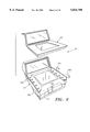
- FIG. 2 is an exploded perspective view of the scanner and weigh platter of FIG. 1 showing an integral load cell
- FIG. 3 is an exploded right side elevation view of the scanner and weigh platter of FIG. 1;
- FIG. 4 is an exploded front perspective view of the scanner and weigh platter of FIG. 1 showing an integral load cell;
- FIG. 5 is a side view of the apparatus of FIGS. 1-4 with an oversized item being weighed;
- FIG. 6 is an exploded view of an alternate apparatus having a spiderless design with multiple load cells
- FIG. 7 is an exploded view of another alternate apparatus having a spider with a load cell
- FIG. 8 is an exploded view of another alternate apparatus also having a spider with a load cell
- FIG. 9 is an exploded view of another alternate apparatus having a spider with multiple load cells.
- FIG. 10 is a side view of a another alternate apparatus illustrating three planes.
- FIGS. 1-5 illustrate a two-plane scanner/weighing apparatus 1 including a scanner 2 with an integral load cell 4 and a two-plane spiderless weigh platter 6.
- the vertical platter window 8 When assembled the vertical platter window 8 is positioned in front of the vertical scan window 10 and the horizontal platter window 12 is positioned over the horizontal scan window 14.
- This relative positioning of the platter windows 8, 12 to the scan windows 10, 14 allows optical beams generated by the scan engine(s) to pass out through the scan windows and platter windows, and allows the resulting optical signals from a scanned barcode to pass in through the platter windows and the scan windows for detection and decoding.
- the window 8 may be oriented perfectly vertical, or it may be angled somewhat from absolute vertical as best shown in FIG. 3.
- the lateral side edges 16, 18 of the horizontal section 20 of the weigh platter 6 and the horizontal scan housing portion 24 form air gaps 26, 28 on the lateral side edges (the right and left sides as viewed in FIG. 1) of the weigh platter 6, while the front edge 30 of the horizontal plane of the weigh platter 6 extends beyond the front 32 edge (i.e., the edge nearest the checker) of the horizontal scanner housing portion 24.
- the back edge 34 of the horizontal section of the weigh platter is rigidly connected to the bottom edge 36 of the vertical section 38 of the weigh platter, thereby forming an integral structure with a continuous surface, thereby preventing debris from passing below the weigh platter 6 which could obstruct the horizontal scan window 14 or could adversely affect scale performance.
- the two-plane weigh platter 6 may be fabricated from a single piece of material (preferably metal) or may be assembled from multiple pieces provided it comprises a single rigid structure as described herein.
- One variation of this embodiment has a horizontal extension 40 of the weigh platter rigidly connected to the top edge 42 of the vertical platter section 38 of the weigh platter.
- This extension of the weigh platter 6 serves to further inhibit passage of debris between the vertical scanner window 10 and the vertical platter window 8 which would obstruct the vertical scanner window 10.
- the extension may be further extended downward behind the back surface 44 of the scanner housing portion 46 (see downward extension 43 in FIG. 5).
- the extended weigh platter may be fabricated in a single piece structure or assembled from multiple pieces provided it comprises a rigid overall structure with the sealed connection 35.
- the horizontal platter window 12 is preferably constructed of a material which is shatter resistant and wear resistant such as sapphire, wear resistant coated glass (such as the wear-resistant glass with diamond-like coating described in U.S. application Ser. No. 07/647,540 which later issued as U.S. Pat. No. 5,594,231), or tin-oxide since items being scanned are often dropped onto or dragged across the horizontal window 12.
- the vertical platter window 8 is generally subject to less impact and scratching action and likely would not require quite as an expensive material as the horizontal window, but should still preferably be constructed to have some scratch and impact resistance. Since the scanner housing windows 10, 14 are protected from impact by the weigh platter windows 8, 12, they need not be constructed from expensive scratch resistant material. Alternately, though the scanner internals would be somewhat more exposed, the housing windows 10, 14 may comprise mere openings (i.e., no glass covers) since the platter windows 8, 12 alone may provide adequate protection for internal components.
- the load cell 4 is shown integrally mounted on the top of the horizontal scanner housing portion 24, and is rigidly but removably connected to the bottom 48 of the two-plane weigh platter 6.
- the integral mounting of the load cell reduces the overall bulk of the two-plane scanner/weighing apparatus 1.
- the spiderless weigh platter 6 is constructed in a manner that insures rigidity sufficient to bear the weight of an object being weighed and sufficient to maintain its two-plane geometry and prevent the vertical scanner housing portion 46 from interfering with the weighing process.
- One such construction would be the incorporation of stiffening ribs 50 into the structure of the platter 6.
- FIGS. 2 and 4 Also depicted in FIGS. 2 and 4 is a coupling mechanism for rigidly but removably connecting the two-plane weigh platter 6 to the load cell 4, comprising a pair of precision machined pins 52 attached to the bottom 48 of the two-plane weigh platter 6, and a mating set of precision machined holes 54 in the load cell 4. Any rigid but removable coupling mechanism may be substituted for the pin/hole mechanism depicted here.
- the two-plane weight platter embodiment solves two of the problems discussed in the background section.
- the weigh platter preferably has bottom extensions which extend below the planar surface of the window 14 to prevent debris or liquids from contacting the window 14.
- the side surfaces (i.e. both lateral sides and the side next to the checker) of the horizontal scan housing portion 24 are sloped to channel debris and liquids down and away from the window 14.
- the sides of the weigh platter 6 may extend downwardly to provide additional baffles to further inhibit debris or liquids from contacting the window 14.
- the downwardly extending sides may be disposed in a trough and be provided with additional spill control and air gap maintenance thereby as disclosed in U.S. Pat. No. 5,410,108, which is incorporated by reference.
- the multiple plane weigh platter 6 also facilitates weighing of oversized objects.
- the object may come in contact with the housing or the counter resulting in inaccurate weight measurement.
- FIG. 5 illustrates the apparatus 1 with an oversized object 75 being weighed on the multiplane platter 6.
- One end of the object rests on the horizontal section 20 and the other end rests on the vertical section 38.
- the bag may even be laid over the vertical housing portion 46 on the horizontal extension 40 of the weigh platter or even onto the downward extension 43 behind the back surface 44 of the vertical scanner housing portion 46.
- the load cell 4 may be incorporated directly into an upper section of the horizontal scanner housing portion 24, instead of comprising a separate subassembly.
- the weigh platter 6 is borne by the load cell 4 either directly or via a spider such as in alternate embodiments described below.
- the weigh platter itself is made sufficiently rigid to bear the object being weighed.
- FIG. 6 illustrates an alternate apparatus 101 in which the load cell 105 (with the holes 154, 154 for the pins) is located at an opposite end of the horizontal scanner housing portion 124 of the scanner 102.
- the weigh platter 106 is more greatly cantilevered, but may be designed to fall within load cell specifications.
- FIG. 6 also illustrates another alternate embodiment comprising multiple load cells 104a, 104b, 104c, 104d spaced about the horizontal portion of the scanner 102. Depending upon particular design constraints, multiple load cells may not require pin connection such as preferred for the single load cell design previously described.
- FIG. 7 illustrates another alternate apparatus 201 having an integral spider 260 having a single load cell 205.
- the spider 260 provides additional stiffness to reduce the rigidity required of the weigh platter itself, the two-plane weigh platter 206 should still possess rigidity sufficient to maintain its two-plane geometry and prevent the vertical scanner section 246 of the scanner 202 from interfering with the weighing process.
- the load cell 205, spider 260, and two-plane weigh platter 206 may comprise a separate subassembly from the horizontal scanner housing portion 24 and vertical scanner housing portion 246.
- the load cell 205 is placed between the vertical housing portion 246 and the horizontal housing portion and rigidly connected to the spider by suitable horizontal or vertical support members.
- FIG. 8 illustrates another alternate apparatus 301 having an integral spider 360 having a single load cell 305.
- the two-plane weigh platter 306 possesses rigidity sufficient to maintain its two-plane geometry and prevent the vertical scanner section 346 of the scanner 302 from interfering with the weighing process.
- the load cell 305 is placed on an end of the horizontal scan housing portion 324 opposite to the vertical housing portion 346 (i.e. on the checker side).
- Spider designs may also incorporate multiple load cells.
- separate spider legs 460, 462 (they could be connected as a single spider as in FIG. 8 for example) are mounted on load cells 405, 404 respectively.
- the spider legs 460, 462 provide additional stiffness to reduce the rigidity required of the weigh platter 406 itself, but the two-plane weigh platter 206 should still possess rigidity sufficient to maintain its two-plane geometry and prevent the vertical scanner section 446 of the scanner 402 from interfering with the weighing process.
- the load cell may located within the scanner envelop (such as load cell 205 in FIG. 7) or outside such as load cell 305 as illustrated in FIG. 8.
- the spider may be incorporated outside the scanner envelop (such as spider 360 in FIG. 8) or alternately inside the scanner envelop (such as spider 260 in FIG. 7) depending upon the specific apparatus configuration.
- the disclosed embodiments of the multiple plane weigh platter may be combined with any suitable weighing device and with any multiple plane optical reading device without altering the concept of the present invention.
- the platter may merely comprise a cover for a multi-plane scanner (i.e. a scanner having no scale).
- the multi-plane cover would still provide spill and mechanical protection for the internal components, but may not require as stiff a construction as does the weigh platter scale version.
- multi-plane weigh platter has been shown and described with respect to a laser scanner such as the Spectra-Physics MAGELLANTM scanner, it is intended that scanner upon which the weigh platter is constructed may comprise any sort of data reading device including scanning laser beam(s), CCD, video, LED, or the like.
- multi-plane weigh platter has been described as useful for multi-plane scanner, it may also be used in a single plane (either horizontal or vertical) that may have additional components. Envision for example a scanner/scale 1 of FIG. 1 having only a vertical window and no horizontal window. A multi-plane weigh platter for such a scanner/scale would only require a a vertical window (the horizontal portion could be entirely opaque).
- a three-plane apparatus 501 is illustrated having two vertical scan housing portions 546, 545 and a horizontal scan housing portion 524.
- Such a device may have one, two or three windows through which scanning may be accomplished.
- the multi-plane cover or weigh platter 506 has two vertical sections 538, 539 and a horizontal section 520. Each platter section has a window (if required) corresponding to each respective scan housing window.
- the vertical platter sections may include horizontal extensions 540, 541 and further include downwardly extending vertical extensions 543, 544 if desired to provide further protection.
Abstract
Description
Claims (25)
Priority Applications (3)
| Application Number | Priority Date | Filing Date | Title |
|---|---|---|---|
| US08/539,584 US5834708A (en) | 1995-06-08 | 1995-10-05 | Multiple plane weigh platter for multiple plane scanning systems |
| US09/150,552 US6237852B1 (en) | 1995-06-08 | 1998-09-09 | Multiple plane weigh platter for multiple plane scanning systems |
| US10/447,746 USRE40071E1 (en) | 1995-06-08 | 2003-05-28 | Multiple plane weigh platter for multiple plane scanning systems |
Applications Claiming Priority (2)
| Application Number | Priority Date | Filing Date | Title |
|---|---|---|---|
| US5295P | 1995-06-08 | 1995-06-08 | |
| US08/539,584 US5834708A (en) | 1995-06-08 | 1995-10-05 | Multiple plane weigh platter for multiple plane scanning systems |
Related Child Applications (2)
| Application Number | Title | Priority Date | Filing Date |
|---|---|---|---|
| US09/150,552 Division US6237852B1 (en) | 1995-06-08 | 1998-09-09 | Multiple plane weigh platter for multiple plane scanning systems |
| US09/150,552 Continuation US6237852B1 (en) | 1995-06-08 | 1998-09-09 | Multiple plane weigh platter for multiple plane scanning systems |
Publications (1)
| Publication Number | Publication Date |
|---|---|
| US5834708A true US5834708A (en) | 1998-11-10 |
Family
ID=26667169
Family Applications (3)
| Application Number | Title | Priority Date | Filing Date |
|---|---|---|---|
| US08/539,584 Expired - Lifetime US5834708A (en) | 1995-06-08 | 1995-10-05 | Multiple plane weigh platter for multiple plane scanning systems |
| US09/150,552 Ceased US6237852B1 (en) | 1995-06-08 | 1998-09-09 | Multiple plane weigh platter for multiple plane scanning systems |
| US10/447,746 Expired - Lifetime USRE40071E1 (en) | 1995-06-08 | 2003-05-28 | Multiple plane weigh platter for multiple plane scanning systems |
Family Applications After (2)
| Application Number | Title | Priority Date | Filing Date |
|---|---|---|---|
| US09/150,552 Ceased US6237852B1 (en) | 1995-06-08 | 1998-09-09 | Multiple plane weigh platter for multiple plane scanning systems |
| US10/447,746 Expired - Lifetime USRE40071E1 (en) | 1995-06-08 | 2003-05-28 | Multiple plane weigh platter for multiple plane scanning systems |
Country Status (1)
| Country | Link |
|---|---|
| US (3) | US5834708A (en) |
Cited By (54)
| Publication number | Priority date | Publication date | Assignee | Title |
|---|---|---|---|---|
| US6085979A (en) * | 1998-06-23 | 2000-07-11 | Ncr Corporation | Off-scale item sensing apparatus and method for a bar code reader |
| EP1039275A1 (en) * | 1999-03-23 | 2000-09-27 | NRC International Inc. | Retail terminal having a product scale which has an overlay member secured thereto |
| US6206285B1 (en) * | 1996-10-01 | 2001-03-27 | Siemens Nixdorf Informationssysteme Aktiengesellschaft | Peripheral assembly kit for the workstation of a goods invoicing system |
| US6265675B1 (en) * | 1998-07-17 | 2001-07-24 | Francotyp-Postalia Ag & Co. | Apparatus for weighing moving postal matter |
| US6481626B1 (en) * | 1998-12-09 | 2002-11-19 | Ncr Corporation | Flush scanner window |
| US20030001010A1 (en) * | 2000-04-18 | 2003-01-02 | Mark Schmidt | Point-of-sale (POS) station having a based bar code driven cash register system with an integrated internet-enabled customer-kiosk terminal |
| US6502753B2 (en) | 2001-02-26 | 2003-01-07 | Ncr Corporation | Compact dual aperture scanner |
| US20030052173A1 (en) * | 2000-04-18 | 2003-03-20 | Adaptive Optics Associates, Inc. | Polygon-based bioptical POS scanning system employing dual independent optics platforms disposed beneath horizontal and vertical scanning windows |
| US20030141367A1 (en) * | 2002-01-11 | 2003-07-31 | Metrologic Instruments, Inc. | Modular omnidirectional bar code symbol scanning system with at least one service port for removable installation of a scan module insert |
| US6631844B1 (en) * | 1998-10-21 | 2003-10-14 | Fujitsu Limited | Optical scanner, code reader and bar code reader having increased degree of freedom in placement of optical parts |
| US20040108383A1 (en) * | 2002-01-11 | 2004-06-10 | Timothy Good | Bioptical laser scanner for six-sided 360 pos-based scanning |
| US20040155107A1 (en) * | 2001-07-12 | 2004-08-12 | Psc Scanning, Inc. | Method and apparatus to prevent reporting multiple reads of optical coded items |
| EP1479054A2 (en) * | 2002-02-01 | 2004-11-24 | PSC Scanning, Inc. | Combined data reader and electronic article surveillance (eas) system |
| US6830186B1 (en) * | 2002-08-21 | 2004-12-14 | Ncr Corporation | Checkout device with produce guard |
| US20050098634A1 (en) * | 2000-04-18 | 2005-05-12 | Metrologic Instruments, Inc. | Bioptical laser scanning system providing 360° of omnidirectional bar code symbol scanning coverage at point of sale station |
| US20050109848A1 (en) * | 2002-01-11 | 2005-05-26 | Metrologic Instruments, Inc. | Bioptical laser scanning system providing 360° of omnidirectional bar code symbol scanning coverage at point of sale station |
| US6899272B2 (en) * | 2000-05-17 | 2005-05-31 | Symbol Technologies, Inc | Bioptics bar code reader |
| US20060131416A1 (en) * | 2004-12-21 | 2006-06-22 | Chin-Hung Jwo | Scanner with vertical plate force detection and compensation |
| US7273655B2 (en) | 1999-04-09 | 2007-09-25 | Shojiro Miyake | Slidably movable member and method of producing same |
| US7348501B1 (en) * | 2001-12-19 | 2008-03-25 | Ncr Corporation | Scale having surface plate that provides sole structural connection of its support members |
| US20080151328A1 (en) * | 2006-12-20 | 2008-06-26 | Gregerson David L | Optical scanner with floating load cell frame |
| US20090306924A1 (en) * | 2008-06-10 | 2009-12-10 | Datalogic Scanning, Inc. | Automatic calibration system for scanner-scale or other scale system |
| US20090321518A1 (en) * | 2008-05-08 | 2009-12-31 | Barron Peter B | Item checkout device and weigh plate with improved electromagnetic field performance |
| US7650976B2 (en) | 2003-08-22 | 2010-01-26 | Nissan Motor Co., Ltd. | Low-friction sliding member in transmission, and transmission oil therefor |
| US20100148967A1 (en) * | 2005-02-08 | 2010-06-17 | Datalogic Scanning, Inc. | Integrated data reader and electronic article surveillance (eas) system |
| US7753269B2 (en) | 2002-01-11 | 2010-07-13 | Metrologic Instruments, Inc. | POS-based code driven retail transaction system configured to enable the reading of code symbols on cashier and customer sides thereof, during a retail transaction being carried out at a point-of-sale (POS) station, and driven by a retail transaction application program |
| US7771821B2 (en) | 2003-08-21 | 2010-08-10 | Nissan Motor Co., Ltd. | Low-friction sliding member and low-friction sliding mechanism using same |
| USD642178S1 (en) * | 2010-01-11 | 2011-07-26 | Datalogic Scanning, Inc. | Weigh platter or cover for a data reader |
| US8006904B2 (en) | 2002-03-18 | 2011-08-30 | Datalogic Scanning, Inc. | Operation monitoring and enhanced host communications in systems employing electronic article surveillance and RFID tags |
| US20110309147A1 (en) * | 2010-06-16 | 2011-12-22 | Symbol Technologies, Inc. | Optical scanner with customer interface |
| US8096205B2 (en) | 2003-07-31 | 2012-01-17 | Nissan Motor Co., Ltd. | Gear |
| EP2427853A2 (en) * | 2009-05-06 | 2012-03-14 | Datalogic Scanning, Inc. | Imaging scanner-scale with low vertical profile |
| US8152377B2 (en) | 2002-11-06 | 2012-04-10 | Nissan Motor Co., Ltd. | Low-friction sliding mechanism |
| US8206035B2 (en) | 2003-08-06 | 2012-06-26 | Nissan Motor Co., Ltd. | Low-friction sliding mechanism, low-friction agent composition and method of friction reduction |
| US20120193407A1 (en) * | 2011-02-02 | 2012-08-02 | Metrologic Instruments, Inc | Pos-based code symbol reading system with integrated scale base and system housing having an improved produce weight capturing surface design |
| US8387882B2 (en) | 2011-07-07 | 2013-03-05 | Metrologic Instruments, Inc. | Decodable indicia reading terminal with a platter to inhibit light reflection |
| US20130056285A1 (en) * | 2011-09-02 | 2013-03-07 | Metrologic Instruments, Inc. | Bioptical point of sale (pos) checkout system employing a retractable weigh platter support subsystem |
| US8523076B2 (en) | 2012-01-10 | 2013-09-03 | Metrologic Instruments, Inc. | Omnidirectional laser scanning bar code symbol reader generating a laser scanning pattern with a highly non-uniform scan density with respect to line orientation |
| CN103339482A (en) * | 2011-02-01 | 2013-10-02 | 赛多利斯称量技术有限责任公司 | Weighing compartment with integrated balance |
| US8575076B2 (en) | 2003-08-08 | 2013-11-05 | Nissan Motor Co., Ltd. | Sliding member and production process thereof |
| US8613393B2 (en) | 2010-06-16 | 2013-12-24 | Symbol Technologies, Inc. | Optical scanner with customer interface |
| USD709888S1 (en) * | 2012-07-02 | 2014-07-29 | Symbol Technologies, Inc. | Bi-optic imaging scanner module |
| USD723560S1 (en) * | 2013-07-03 | 2015-03-03 | Hand Held Products, Inc. | Scanner |
| USD730901S1 (en) * | 2014-06-24 | 2015-06-02 | Hand Held Products, Inc. | In-counter barcode scanner |
| CN104813377A (en) * | 2012-09-28 | 2015-07-29 | 讯宝科技公司 | Arrangement for and method of preventing overhanging weighing platter of scale from tipping at product checkout system and method of mounting and removing the weighing platter without tools |
| US20170241829A1 (en) * | 2016-02-18 | 2017-08-24 | Symbol Technologies, Llc | Method of, and arrangement for, reducing weighing errors associated with a weighing scale at a checkout workstation |
| US20210131859A1 (en) * | 2019-11-01 | 2021-05-06 | Minebea Intec Bovenden GmbH & Co. KG | Scale |
| US11118959B2 (en) * | 2019-12-20 | 2021-09-14 | Zebra Technologies Corporation | Modular off-platter detection assembly for use with barcode readers |
| US11209304B2 (en) | 2019-12-20 | 2021-12-28 | Zebra Technologies Corporation | Barcode reader with off-platter detection |
| US11326933B2 (en) | 2019-12-20 | 2022-05-10 | Zebra Technologies Corporation | Weigh platter assembly with parallax based off-platter detection |
| US11326932B2 (en) | 2019-12-20 | 2022-05-10 | Zebra Technologies Corporation | Weigh platter assembly with off-platter detection |
| US11397104B2 (en) | 2019-12-31 | 2022-07-26 | Datalogic Usa, Inc. | Systems and methods for weigh scale perimeter monitoring for scanner-scales |
| CN114923558A (en) * | 2022-05-05 | 2022-08-19 | 青岛海尔生物医疗股份有限公司 | Weighing device |
| US20230004737A1 (en) * | 2021-06-30 | 2023-01-05 | Zebra Technologies Corporation | Bioptic Barcode Reader and Bioptic Barcode Reader Assembly |
Families Citing this family (29)
| Publication number | Priority date | Publication date | Assignee | Title |
|---|---|---|---|---|
| US6517000B1 (en) | 1999-05-03 | 2003-02-11 | Psc Scanning, Inc. | Dual ended cable for connecting electronic article surveillance antenna with RFID equipment |
| US20020052703A1 (en) * | 2000-10-17 | 2002-05-02 | Tabet Nicolas N. | Automatic calibration system for scanner-scale |
| US6783072B2 (en) * | 2002-02-01 | 2004-08-31 | Psc Scanning, Inc. | Combined data reader and electronic article surveillance (EAS) system |
| EP2287817B1 (en) * | 2002-02-01 | 2012-05-23 | Datalogic Adc, Inc. | Systems and methods for data reading and EAS tag sensing and deactivation at retail checkout |
| US6854647B2 (en) * | 2002-02-01 | 2005-02-15 | Ncr Corporation | Checkout device including integrated barcode reader, scale, and EAS system |
| US6764010B2 (en) * | 2002-05-10 | 2004-07-20 | Ncr Corporation | Checkout device including barcode reading apparatus, scale, and EAS system |
| EP1482190B1 (en) * | 2003-05-27 | 2012-12-05 | Nissan Motor Company Limited | Rolling element |
| US6942145B1 (en) * | 2003-06-11 | 2005-09-13 | Ncr Corporation | Checkout device with enhanced security label detection |
| JP2005054617A (en) * | 2003-08-08 | 2005-03-03 | Nissan Motor Co Ltd | Valve system |
| TWI381318B (en) * | 2004-11-04 | 2013-01-01 | Qelikishi Ltd Llc | Combined barcode scanner and radio frequency identification reader with field interpretation array |
| US8113431B2 (en) * | 2008-02-06 | 2012-02-14 | Ncr Corporation | Scale assembly mounting apparatus for an optical scanner |
| EP2373960B1 (en) * | 2008-12-09 | 2019-02-06 | Datalogic USA, Inc. | Systems and methods for reducing weighing errors associated with partially off-scale items |
| WO2010075581A2 (en) | 2008-12-26 | 2010-07-01 | Datalogic Scanning, Inc. | Two-plane optical code reader for acquisition of multiple views of an object |
| US8556175B2 (en) * | 2009-12-07 | 2013-10-15 | Datalogic ADC, Inc. | Systems and methods for weigh scale perimeter monitoring scanner-scales |
| US8561902B2 (en) * | 2009-12-07 | 2013-10-22 | Datalogic ADC, Inc. | Systems and methods for weigh scale perimeter monitoring for scanner-scales |
| US8430318B2 (en) * | 2010-01-08 | 2013-04-30 | Datalogic ADC, Inc. | System and method for data reading with low profile arrangement |
| US8740075B2 (en) * | 2011-10-06 | 2014-06-03 | Symbol Technologies, Inc. | Apparatus for and method of reading targets arbitrarily oriented in imaging workstations |
| US8365998B1 (en) * | 2012-01-31 | 2013-02-05 | Ncr Corporation | Convertible barcode reader |
| US8804215B2 (en) | 2012-02-02 | 2014-08-12 | Xerox Corporation | Image input terminal having weighing platen |
| US9064395B2 (en) | 2012-06-08 | 2015-06-23 | Datalogic ADC, Inc. | Bezel with non-metallic materials for cover or platter for a data reader in a checkout station |
| USD708183S1 (en) * | 2012-06-08 | 2014-07-01 | Datalogic ADC, Inc. | Data reader for checkout station |
| US9305198B2 (en) | 2012-06-08 | 2016-04-05 | Datalogic ADC, Inc. | Imaging reader with improved illumination |
| US9245425B2 (en) | 2013-02-14 | 2016-01-26 | Symbol Technologies, Llc | Produce lift apparatus |
| US9747485B2 (en) | 2013-04-16 | 2017-08-29 | Symbol Technologies, Llc | Arrangement for and method of cleaning a platter of a product checkout workstation |
| US9400907B2 (en) * | 2013-08-30 | 2016-07-26 | Ncr Corporation | User interface for an optical code scanner |
| US10060785B2 (en) | 2013-10-02 | 2018-08-28 | Datalogic Usa, Inc. | Systems and methods of alternate operation for a scanner-scale having an item overhang detection system |
| US10049247B2 (en) | 2016-10-12 | 2018-08-14 | Datalogic Usa, Inc. | Optimization of image frame management in a sweep-style optical code data reader |
| WO2018201059A1 (en) | 2017-04-27 | 2018-11-01 | Datalogic Usa, Inc. | Self-checkout system with scan gate and exception handling |
| US10970506B2 (en) | 2018-12-21 | 2021-04-06 | Datalogic Usa, Inc. | Bioptic data reader with wide-angle field-of-view |
Citations (14)
| Publication number | Priority date | Publication date | Assignee | Title |
|---|---|---|---|---|
| US2617641A (en) * | 1946-03-18 | 1952-11-11 | Toledo Scale Co | Ratio-indicating weighing scale |
| US2738184A (en) * | 1952-08-30 | 1956-03-13 | Toledo Scale Co | Weighing scale housing support |
| US4064954A (en) * | 1974-09-30 | 1977-12-27 | Rock Frank C | Computing postal scale and method with taring capability |
| US4656344A (en) * | 1985-03-04 | 1987-04-07 | Ncr Corporation | Integrated scale and optical scanner |
| US4669663A (en) * | 1985-04-23 | 1987-06-02 | Nelson Irrigation Company | Large volume sprinkler head with part-circle step by step movements in both directions |
| US4881606A (en) * | 1988-07-15 | 1989-11-21 | Shekel Electronics-Scales Beit Keshet Electronics (Registered Partnership) | Point-of-sale apparatus |
| US4971176A (en) * | 1989-03-24 | 1990-11-20 | Spectra-Physics, Inc. | Data gathering system including cradle suspension |
| US4971177A (en) * | 1989-03-24 | 1990-11-20 | Spectra-Physics, Inc. | Data gathering system housing/mounting |
| US4991692A (en) * | 1989-03-24 | 1991-02-12 | Spectra-Physics | Spill control mounting for data gathering system |
| US5086879A (en) * | 1989-03-24 | 1992-02-11 | Spectra-Physics, Inc. | Scale calibration/zeroing in data gathering system |
| US5139100A (en) * | 1991-02-04 | 1992-08-18 | Point Of Sale Data Products, Inc. | Point-of-sale scanner/scale system with scale activation of scanner |
| US5229588A (en) * | 1991-09-30 | 1993-07-20 | Ncr Corporation | Dual aperture optical scanner |
| US5410108A (en) * | 1992-08-31 | 1995-04-25 | Spectra-Physics Scanning Systems, Inc. | Combined scanner and scale |
| US5475207A (en) * | 1992-07-14 | 1995-12-12 | Spectra-Physics Scanning Systems, Inc. | Multiple plane scanning system for data reading applications |
Family Cites Families (11)
| Publication number | Priority date | Publication date | Assignee | Title |
|---|---|---|---|---|
| CH650337A5 (en) | 1981-04-10 | 1985-07-15 | Mettler Instrumente Ag | ANALYSIS SCALE. |
| US5005670A (en) | 1989-03-24 | 1991-04-09 | Spectra-Physics, Inc. | Method and apparatus for mounting data gathering system |
| US4909338A (en) | 1989-06-12 | 1990-03-20 | Ncr Corporation | Method and apparatus for scale calibration and weighing |
| US5206491A (en) * | 1990-03-02 | 1993-04-27 | Fujitsu Limited | Plural beam, plural window multi-direction bar code reading device |
| US5073702A (en) | 1990-03-26 | 1991-12-17 | Ncr Corporation | Multiple beam bar code scanner |
| US5143164A (en) | 1991-05-23 | 1992-09-01 | Ncr Corporation | Apparatus and method for improving the accuracy of weighing an object |
| US5531293A (en) * | 1994-07-15 | 1996-07-02 | At&T Global Information Solutions Company | Checkout counter gap filler |
| US5588621A (en) * | 1995-02-23 | 1996-12-31 | At&T Global Information Solutions Company | Universal mounting apparatus and method for bar code scanners |
| US5773767A (en) | 1996-08-27 | 1998-06-30 | Ncr Corporation | Scale with reset extender bar |
| US5886336A (en) * | 1996-12-12 | 1999-03-23 | Ncr Corporation | Multiside coverage optical scanner |
| US6830186B1 (en) | 2002-08-21 | 2004-12-14 | Ncr Corporation | Checkout device with produce guard |
-
1995
- 1995-10-05 US US08/539,584 patent/US5834708A/en not_active Expired - Lifetime
-
1998
- 1998-09-09 US US09/150,552 patent/US6237852B1/en not_active Ceased
-
2003
- 2003-05-28 US US10/447,746 patent/USRE40071E1/en not_active Expired - Lifetime
Patent Citations (14)
| Publication number | Priority date | Publication date | Assignee | Title |
|---|---|---|---|---|
| US2617641A (en) * | 1946-03-18 | 1952-11-11 | Toledo Scale Co | Ratio-indicating weighing scale |
| US2738184A (en) * | 1952-08-30 | 1956-03-13 | Toledo Scale Co | Weighing scale housing support |
| US4064954A (en) * | 1974-09-30 | 1977-12-27 | Rock Frank C | Computing postal scale and method with taring capability |
| US4656344A (en) * | 1985-03-04 | 1987-04-07 | Ncr Corporation | Integrated scale and optical scanner |
| US4669663A (en) * | 1985-04-23 | 1987-06-02 | Nelson Irrigation Company | Large volume sprinkler head with part-circle step by step movements in both directions |
| US4881606A (en) * | 1988-07-15 | 1989-11-21 | Shekel Electronics-Scales Beit Keshet Electronics (Registered Partnership) | Point-of-sale apparatus |
| US4971176A (en) * | 1989-03-24 | 1990-11-20 | Spectra-Physics, Inc. | Data gathering system including cradle suspension |
| US4971177A (en) * | 1989-03-24 | 1990-11-20 | Spectra-Physics, Inc. | Data gathering system housing/mounting |
| US4991692A (en) * | 1989-03-24 | 1991-02-12 | Spectra-Physics | Spill control mounting for data gathering system |
| US5086879A (en) * | 1989-03-24 | 1992-02-11 | Spectra-Physics, Inc. | Scale calibration/zeroing in data gathering system |
| US5139100A (en) * | 1991-02-04 | 1992-08-18 | Point Of Sale Data Products, Inc. | Point-of-sale scanner/scale system with scale activation of scanner |
| US5229588A (en) * | 1991-09-30 | 1993-07-20 | Ncr Corporation | Dual aperture optical scanner |
| US5475207A (en) * | 1992-07-14 | 1995-12-12 | Spectra-Physics Scanning Systems, Inc. | Multiple plane scanning system for data reading applications |
| US5410108A (en) * | 1992-08-31 | 1995-04-25 | Spectra-Physics Scanning Systems, Inc. | Combined scanner and scale |
Non-Patent Citations (16)
| Title |
|---|
| Brochure from NCR web page on the NCR Model 7870 Bi Optic Scanner and Scanner/Scale (http://www.ncr.com/product/retail/products/catalog/7870.shtml) (1997) no month. * |
| Brochure from NCR web page on the NCR Model 7870 Bi-Optic Scanner and Scanner/Scale (http://www.ncr.com/product/retail/products/catalog/7870.shtml) (1997) no month. |
| Brochure from NCR web page on the NCR Model 7875 Bi Optic Aggressive Read Scanner/Scale (http://www.ncr.com./product/retail/products/catalog/7870.shtml) (1997) no month. * |
| Brochure from NCR web page on the NCR Model 7875 Bi-Optic Aggressive Read Scanner/Scale (http://www.ncr.com./product/retail/products/catalog/7870.shtml) (1997) no month. |
| ICL Datachecker brochure on the Orion Scanner/Scale (about 1989) no date. * |
| ICL Datachecker brochure on the Orion Scanner/Scale entitled A Total Scanning Solution (undated) no date. * |
| ICL Model 9500 Scanner/Scale brochure, ICL Retail Systems, Dallas, TX (about 1997) no date. * |
| NCI Brochure on the NCI Model 4710 Scanner Scale (undated) no date. * |
| NCR Model 7870 Scanner/Scale Product Model excerpts (pp. i, xiii through xvi, 3 16 through 3 18) (1993) no month. * |
| NCR Model 7870 Scanner/Scale Product Model excerpts (pp. i, xiii through xvi, 3-16 through 3-18) (1993) no month. |
| Orion Scanner and Scale Installation and Maintenance Manual, pp. A1 A3 (1989) no month. * |
| Orion Scanner and Scale Installation and Maintenance Manual, pp. A1-A3 (1989) no month. |
| PSC Inc. brochure from PSC web page on the Magellan Scanner/Scale (http://www.pscnet.com/magelspe.htm) (1997) no month. * |
| PSC Inc. brochure from PSC web page on the Magellan® Scanner/Scale (http://www.pscnet.com/magelspe.htm) (1997) no month. |
| Spectra Physics brochure on the Scanning Scale Model 760SLS (about 1989) no date. * |
| Spectra-Physics' brochure on the Scanning Scale Model 760SLS (about 1989) no date. |
Cited By (108)
| Publication number | Priority date | Publication date | Assignee | Title |
|---|---|---|---|---|
| US6206285B1 (en) * | 1996-10-01 | 2001-03-27 | Siemens Nixdorf Informationssysteme Aktiengesellschaft | Peripheral assembly kit for the workstation of a goods invoicing system |
| US6085979A (en) * | 1998-06-23 | 2000-07-11 | Ncr Corporation | Off-scale item sensing apparatus and method for a bar code reader |
| US6265675B1 (en) * | 1998-07-17 | 2001-07-24 | Francotyp-Postalia Ag & Co. | Apparatus for weighing moving postal matter |
| US6631844B1 (en) * | 1998-10-21 | 2003-10-14 | Fujitsu Limited | Optical scanner, code reader and bar code reader having increased degree of freedom in placement of optical parts |
| US6481626B1 (en) * | 1998-12-09 | 2002-11-19 | Ncr Corporation | Flush scanner window |
| EP1039275A1 (en) * | 1999-03-23 | 2000-09-27 | NRC International Inc. | Retail terminal having a product scale which has an overlay member secured thereto |
| US7273655B2 (en) | 1999-04-09 | 2007-09-25 | Shojiro Miyake | Slidably movable member and method of producing same |
| US7841524B2 (en) | 2000-04-18 | 2010-11-30 | Metrologic Instruments, Inc. | POS-based checkout system configured to enable the reading of code symbols on cashier and customer sides thereof, during a retail transaction being carried out at a point-of-sale (POS) station |
| US20030015588A1 (en) * | 2000-04-18 | 2003-01-23 | Metrologic Instruments, Inc. | Point-of-sale (POS) based bar code driven cash register system with an integrated internet-enabled customer-kiosk terminal |
| US20030052173A1 (en) * | 2000-04-18 | 2003-03-20 | Adaptive Optics Associates, Inc. | Polygon-based bioptical POS scanning system employing dual independent optics platforms disposed beneath horizontal and vertical scanning windows |
| US7100832B2 (en) | 2000-04-18 | 2006-09-05 | Metrologic Instruments, Inc. | Bioptical laser scanning system providing 360° of omnidirectional bar code symbol scanning coverage at point of sale station |
| US20030010825A1 (en) * | 2000-04-18 | 2003-01-16 | Mark Schmidt | Point of sale (POS) based bar code reading system with integrated internet-enabled customer-kiosk terminal |
| US20050098634A1 (en) * | 2000-04-18 | 2005-05-12 | Metrologic Instruments, Inc. | Bioptical laser scanning system providing 360° of omnidirectional bar code symbol scanning coverage at point of sale station |
| US20040016813A1 (en) * | 2000-04-18 | 2004-01-29 | Metrologic Instruments, Inc. | Bioptical laser scanning system providing 360 degree of omnidirectional bar code symbol scanning coverage at point of sale station |
| US7341192B2 (en) | 2000-04-18 | 2008-03-11 | Metrologic Instruments, Inc. | Method of generating a complex laser scanning pattern from a bioptical laser scanning system for providing 360° of omnidirectional bar code symbol scanning coverage at a point of sale station |
| US6951304B2 (en) * | 2000-04-18 | 2005-10-04 | Metrologic Instruments, Inc. | Polygon-based bioptical pos scanning system employing dual independent optics platforms disposed beneath horizontal and vertical scanning windows |
| US6814292B2 (en) | 2000-04-18 | 2004-11-09 | Metrologic Instruments, Inc. | Bioptical laser scanning system providing 360° of omnidirectional bar code symbol scanning coverage at point of sale station |
| US20070257110A1 (en) * | 2000-04-18 | 2007-11-08 | Metrologic Instruments, Inc. | Point of sale (POS) based bar code reading and cash register systems with integrated Internet-enabled customer-kiosk terminals |
| US20030001010A1 (en) * | 2000-04-18 | 2003-01-02 | Mark Schmidt | Point-of-sale (POS) station having a based bar code driven cash register system with an integrated internet-enabled customer-kiosk terminal |
| US6899272B2 (en) * | 2000-05-17 | 2005-05-31 | Symbol Technologies, Inc | Bioptics bar code reader |
| US6502753B2 (en) | 2001-02-26 | 2003-01-07 | Ncr Corporation | Compact dual aperture scanner |
| US20040155107A1 (en) * | 2001-07-12 | 2004-08-12 | Psc Scanning, Inc. | Method and apparatus to prevent reporting multiple reads of optical coded items |
| US6932273B2 (en) | 2001-07-12 | 2005-08-23 | Psc Scanning, Inc. | Method and apparatus to prevent reporting multiple reads of optical coded items |
| US7348501B1 (en) * | 2001-12-19 | 2008-03-25 | Ncr Corporation | Scale having surface plate that provides sole structural connection of its support members |
| US7753269B2 (en) | 2002-01-11 | 2010-07-13 | Metrologic Instruments, Inc. | POS-based code driven retail transaction system configured to enable the reading of code symbols on cashier and customer sides thereof, during a retail transaction being carried out at a point-of-sale (POS) station, and driven by a retail transaction application program |
| US7314176B2 (en) | 2002-01-11 | 2008-01-01 | Metrologic Instruments, Inc. | Method of generating a complex laser scanning pattern from a bioptical laser scanning system for providing 360° of omnidirectional bar code symbol scanning coverage at a point of sale station |
| US20050103852A1 (en) * | 2002-01-11 | 2005-05-19 | Metrologic Instruments, Inc. | Modular omnidirectional bar code symbol scanning system with at least one service port for removable installation of scan module insert |
| US6874690B2 (en) | 2002-01-11 | 2005-04-05 | Metrologic Instruments, Inc. | Modular omnidirectional bar code symbol scanning system with at least one service port for removable installation of scan module insert |
| US6969004B2 (en) | 2002-01-11 | 2005-11-29 | Metrologic Instruments, Inc. | Bar code symbol scanning system employing time-division multiplexed laser scanning and signal processing to avoid optical cross-talk and other unwanted light interference |
| US20030136843A1 (en) * | 2002-01-11 | 2003-07-24 | Metrologic Instruments, Inc. | Bar code symbol scanning system employing time-division multiplexed laser scanning and signal processing to avoid optical cross-talk and other unwanted light interference |
| US7083102B2 (en) | 2002-01-11 | 2006-08-01 | Metrologic Instruments, Inc. | Bioptical laser scanner for six-sided 360° Pos-based scanning |
| US7086597B2 (en) | 2002-01-11 | 2006-08-08 | Metrologic Instruments, Inc. | Bioptical laser scanning system providing 360 degree of omnidirectional bar code symbol scanning coverage at point of sale station |
| US20050061888A1 (en) * | 2002-01-11 | 2005-03-24 | Metrologic Instruments, Inc. | Bioptical laser scanning system providing 360 degree of omnidirectional bar code symbol scanning coverage at point of sale station |
| US20070029389A1 (en) * | 2002-01-11 | 2007-02-08 | Metrologic Instruments, Inc. | Bioptical laser scanner for six-sided 360º POS-based scanning |
| US7195167B2 (en) | 2002-01-11 | 2007-03-27 | Metrologic Instruments, Inc. | Modular omnidirectional bar code symbol scanning system with at least one service port for removable installation of scan module insert |
| US20050109848A1 (en) * | 2002-01-11 | 2005-05-26 | Metrologic Instruments, Inc. | Bioptical laser scanning system providing 360° of omnidirectional bar code symbol scanning coverage at point of sale station |
| US20030132291A1 (en) * | 2002-01-11 | 2003-07-17 | Metrologic Instruments, Inc. | Point of sale (POS) station having bar code reading system with integrated internet-enabled customer-kiosk terminal |
| US7510118B2 (en) | 2002-01-11 | 2009-03-31 | Metrologic Instruments, Inc. | Bar code symbol scanning system employing time-division multiplexed laser scanning and signal processing to avoid optical cross-talk and other unwanted light interference |
| US7296748B2 (en) | 2002-01-11 | 2007-11-20 | Metrologic Instruments, Inc. | Bioptical laser scanning system providing 360° of omnidirectional bar code symbol scanning coverage at point of sale station |
| US7740175B2 (en) | 2002-01-11 | 2010-06-22 | Metrologic Instruments, Inc. | Point-of-sale (POS) based laser scanning system providing six-sided 360 degree omni-directional bar code symbol scanning coverage at a POS station |
| US7383996B2 (en) | 2002-01-11 | 2008-06-10 | Metrologic Instruments, Inc. | Bioptical laser scanner for six-sided 360° POS-based scanning |
| US20040108383A1 (en) * | 2002-01-11 | 2004-06-10 | Timothy Good | Bioptical laser scanner for six-sided 360 pos-based scanning |
| US20030141367A1 (en) * | 2002-01-11 | 2003-07-31 | Metrologic Instruments, Inc. | Modular omnidirectional bar code symbol scanning system with at least one service port for removable installation of a scan module insert |
| EP1479054A2 (en) * | 2002-02-01 | 2004-11-24 | PSC Scanning, Inc. | Combined data reader and electronic article surveillance (eas) system |
| EP1479054A4 (en) * | 2002-02-01 | 2010-05-12 | Datalogic Scanning Inc | Combined data reader and electronic article surveillance (eas) system |
| US8006904B2 (en) | 2002-03-18 | 2011-08-30 | Datalogic Scanning, Inc. | Operation monitoring and enhanced host communications in systems employing electronic article surveillance and RFID tags |
| US6830186B1 (en) * | 2002-08-21 | 2004-12-14 | Ncr Corporation | Checkout device with produce guard |
| US8152377B2 (en) | 2002-11-06 | 2012-04-10 | Nissan Motor Co., Ltd. | Low-friction sliding mechanism |
| US8096205B2 (en) | 2003-07-31 | 2012-01-17 | Nissan Motor Co., Ltd. | Gear |
| US8206035B2 (en) | 2003-08-06 | 2012-06-26 | Nissan Motor Co., Ltd. | Low-friction sliding mechanism, low-friction agent composition and method of friction reduction |
| US8575076B2 (en) | 2003-08-08 | 2013-11-05 | Nissan Motor Co., Ltd. | Sliding member and production process thereof |
| US7771821B2 (en) | 2003-08-21 | 2010-08-10 | Nissan Motor Co., Ltd. | Low-friction sliding member and low-friction sliding mechanism using same |
| US7650976B2 (en) | 2003-08-22 | 2010-01-26 | Nissan Motor Co., Ltd. | Low-friction sliding member in transmission, and transmission oil therefor |
| WO2006068831A3 (en) * | 2004-12-21 | 2007-04-12 | Symbol Technologies Inc | Scanner with vertical plate force detection and compensation |
| US20060131416A1 (en) * | 2004-12-21 | 2006-06-22 | Chin-Hung Jwo | Scanner with vertical plate force detection and compensation |
| EP1880347A4 (en) * | 2004-12-21 | 2009-12-23 | Symbol Technologies Inc | Scanner with vertical plate force detection and compensation |
| EP1880347A2 (en) * | 2004-12-21 | 2008-01-23 | Symbol Technologies, Inc. | Scanner with vertical plate force detection and compensation |
| US7367499B2 (en) | 2004-12-21 | 2008-05-06 | Symbol Technologies, Inc. | Scanner with vertical plate force detection and compensation |
| US20100148967A1 (en) * | 2005-02-08 | 2010-06-17 | Datalogic Scanning, Inc. | Integrated data reader and electronic article surveillance (eas) system |
| US8358211B2 (en) | 2005-02-08 | 2013-01-22 | Datalogic ADC, Inc. | Integrated data reader and electronic article surveillance (EAS) system |
| US20080151328A1 (en) * | 2006-12-20 | 2008-06-26 | Gregerson David L | Optical scanner with floating load cell frame |
| US8365992B2 (en) * | 2006-12-20 | 2013-02-05 | Ncr Corporation | Optical scanner with floating load cell frame |
| US8033461B2 (en) * | 2008-05-08 | 2011-10-11 | Ncr Corporation | Item checkout device and weigh plate with improved electromagnetic field performance |
| US20090321518A1 (en) * | 2008-05-08 | 2009-12-31 | Barron Peter B | Item checkout device and weigh plate with improved electromagnetic field performance |
| US20090306924A1 (en) * | 2008-06-10 | 2009-12-10 | Datalogic Scanning, Inc. | Automatic calibration system for scanner-scale or other scale system |
| EP2427853A2 (en) * | 2009-05-06 | 2012-03-14 | Datalogic Scanning, Inc. | Imaging scanner-scale with low vertical profile |
| EP2427853A4 (en) * | 2009-05-06 | 2014-02-26 | Datalogic Scanning Inc | Imaging scanner-scale with low vertical profile |
| USD659142S1 (en) | 2010-01-11 | 2012-05-08 | Datalogic ADC, Inc. | Weigh platter or cover for a data reader |
| USD676446S1 (en) | 2010-01-11 | 2013-02-19 | Datalogic ADC, Inc. | Weigh platter or cover for a data reader |
| USD642178S1 (en) * | 2010-01-11 | 2011-07-26 | Datalogic Scanning, Inc. | Weigh platter or cover for a data reader |
| US20110309147A1 (en) * | 2010-06-16 | 2011-12-22 | Symbol Technologies, Inc. | Optical scanner with customer interface |
| US8613393B2 (en) | 2010-06-16 | 2013-12-24 | Symbol Technologies, Inc. | Optical scanner with customer interface |
| US8479997B2 (en) * | 2010-06-16 | 2013-07-09 | Symbol Technologies, Inc. | Optical scanner with customer interface |
| US9523603B2 (en) * | 2011-02-01 | 2016-12-20 | Sartorius Lab Instruments Gmbh & Co. Kg | Weighing compartment with integrated balance |
| CN103339482B (en) * | 2011-02-01 | 2015-08-12 | 赛多利斯实验室仪器有限责任两合公司 | There is the weighing chamber of integrated scale |
| US20130333957A1 (en) * | 2011-02-01 | 2013-12-19 | Sartorius Weighing Technology Gmbh | Weighing compartment with integrated balance |
| CN103339482A (en) * | 2011-02-01 | 2013-10-02 | 赛多利斯称量技术有限责任公司 | Weighing compartment with integrated balance |
| US9305201B2 (en) | 2011-02-02 | 2016-04-05 | Metrologic Instruments, Inc. | Symbol reading system with integrated scale base |
| US20120193407A1 (en) * | 2011-02-02 | 2012-08-02 | Metrologic Instruments, Inc | Pos-based code symbol reading system with integrated scale base and system housing having an improved produce weight capturing surface design |
| US8789757B2 (en) * | 2011-02-02 | 2014-07-29 | Metrologic Instruments, Inc. | POS-based code symbol reading system with integrated scale base and system housing having an improved produce weight capturing surface design |
| EP2485176A2 (en) | 2011-02-02 | 2012-08-08 | Metrologic Instruments, Inc. | POS-based code symbol reading system with integrated scale base and system housing having an improved produce weight capturing surface design |
| EP2485176A3 (en) * | 2011-02-02 | 2012-11-14 | Metrologic Instruments, Inc. | POS-based code symbol reading system with integrated scale base and system housing having an improved produce weight capturing surface design |
| US8387882B2 (en) | 2011-07-07 | 2013-03-05 | Metrologic Instruments, Inc. | Decodable indicia reading terminal with a platter to inhibit light reflection |
| US20130056285A1 (en) * | 2011-09-02 | 2013-03-07 | Metrologic Instruments, Inc. | Bioptical point of sale (pos) checkout system employing a retractable weigh platter support subsystem |
| US8822848B2 (en) * | 2011-09-02 | 2014-09-02 | Metrologic Instruments, Inc. | Bioptical point of sale (POS) checkout system employing a retractable weigh platter support subsystem |
| US8523076B2 (en) | 2012-01-10 | 2013-09-03 | Metrologic Instruments, Inc. | Omnidirectional laser scanning bar code symbol reader generating a laser scanning pattern with a highly non-uniform scan density with respect to line orientation |
| USD709888S1 (en) * | 2012-07-02 | 2014-07-29 | Symbol Technologies, Inc. | Bi-optic imaging scanner module |
| CN104813377A (en) * | 2012-09-28 | 2015-07-29 | 讯宝科技公司 | Arrangement for and method of preventing overhanging weighing platter of scale from tipping at product checkout system and method of mounting and removing the weighing platter without tools |
| US9797766B2 (en) | 2012-09-28 | 2017-10-24 | Symbol Technologies, Llc | Application for and method of preventing overhanging weighing platter of scale from tipping at product checkout system and method of mounting and removing the weighing platter without tools |
| USD826233S1 (en) | 2013-07-03 | 2018-08-21 | Hand Held Products, Inc. | Scanner |
| USD766244S1 (en) | 2013-07-03 | 2016-09-13 | Hand Held Products, Inc. | Scanner |
| USD723560S1 (en) * | 2013-07-03 | 2015-03-03 | Hand Held Products, Inc. | Scanner |
| USD757009S1 (en) | 2014-06-24 | 2016-05-24 | Hand Held Products, Inc. | In-counter barcode scanner |
| USD730901S1 (en) * | 2014-06-24 | 2015-06-02 | Hand Held Products, Inc. | In-counter barcode scanner |
| US20170241829A1 (en) * | 2016-02-18 | 2017-08-24 | Symbol Technologies, Llc | Method of, and arrangement for, reducing weighing errors associated with a weighing scale at a checkout workstation |
| US10422689B2 (en) * | 2016-02-18 | 2019-09-24 | Symbol Technologies, Llc | Method of, and arrangement for, reducing weighing errors associated with a weighing scale at a checkout workstation |
| US20210131859A1 (en) * | 2019-11-01 | 2021-05-06 | Minebea Intec Bovenden GmbH & Co. KG | Scale |
| US11435222B2 (en) * | 2019-11-01 | 2022-09-06 | Minebea Intec Bovenden GmbH & Co. KG | Scale in which at least one bearing plate has a high stiffness geometric shape |
| US11209304B2 (en) | 2019-12-20 | 2021-12-28 | Zebra Technologies Corporation | Barcode reader with off-platter detection |
| US11326933B2 (en) | 2019-12-20 | 2022-05-10 | Zebra Technologies Corporation | Weigh platter assembly with parallax based off-platter detection |
| US11326932B2 (en) | 2019-12-20 | 2022-05-10 | Zebra Technologies Corporation | Weigh platter assembly with off-platter detection |
| US20220260411A1 (en) * | 2019-12-20 | 2022-08-18 | Zebra Technologies Corporation | Weigh Platter Assembly with Parallax Based Off-Platter Detection |
| US11118959B2 (en) * | 2019-12-20 | 2021-09-14 | Zebra Technologies Corporation | Modular off-platter detection assembly for use with barcode readers |
| US11725978B2 (en) * | 2019-12-20 | 2023-08-15 | Zebra Technologies Corporation | Weigh platter assembly with parallax based off-platter detection |
| US11397104B2 (en) | 2019-12-31 | 2022-07-26 | Datalogic Usa, Inc. | Systems and methods for weigh scale perimeter monitoring for scanner-scales |
| US20230004737A1 (en) * | 2021-06-30 | 2023-01-05 | Zebra Technologies Corporation | Bioptic Barcode Reader and Bioptic Barcode Reader Assembly |
| CN114923558A (en) * | 2022-05-05 | 2022-08-19 | 青岛海尔生物医疗股份有限公司 | Weighing device |
| CN114923558B (en) * | 2022-05-05 | 2023-06-16 | 青岛海尔生物医疗股份有限公司 | Weighing device |
Also Published As
| Publication number | Publication date |
|---|---|
| US6237852B1 (en) | 2001-05-29 |
| USRE40071E1 (en) | 2008-02-19 |
Similar Documents
| Publication | Publication Date | Title |
|---|---|---|
| US5834708A (en) | Multiple plane weigh platter for multiple plane scanning systems | |
| EP2427853B1 (en) | Imaging scanner-scale with low vertical profile | |
| CA1265248A (en) | Integrated scale and optical scanner | |
| US7491905B2 (en) | Scanner with vertical plate force detection and compensation | |
| US9004359B2 (en) | Optical scanner with top down reader | |
| EP2593902B1 (en) | System and method for data reading with low profile arrangement | |
| US6457644B1 (en) | Item checkout device including a bar code data collector and a produce data collector | |
| EP2715608B1 (en) | Systems and methods for weigh scale perimeter monitoring for scanner-scales | |
| US9064395B2 (en) | Bezel with non-metallic materials for cover or platter for a data reader in a checkout station | |
| US8113431B2 (en) | Scale assembly mounting apparatus for an optical scanner | |
| CN102763120A (en) | Systems and methods for weigh scale perimeter monitoring for scanner-scales | |
| JPH02291926A (en) | Housing/mounting apparatus for data collection system | |
| EP0967565A2 (en) | Item position sensing apparatus and method for a bar code reader | |
| EP3845876B1 (en) | Systems and methods for weigh scale perimeter monitoring for scanner-scales | |
| US5033562A (en) | Weigh plate quick release mount | |
| EP0388560A2 (en) | Data gathering system interface | |
| EP0430680A2 (en) | Weigh plate quick release mount | |
| US6830186B1 (en) | Checkout device with produce guard | |
| US7554042B2 (en) | Methods and apparatus for multiple support and weight measurement points in a scanner scale combination | |
| US4991692A (en) | Spill control mounting for data gathering system | |
| EP0534641A2 (en) | Optical scanner weigh plate mounting apparatus | |
| JPH11203385A (en) | Scanner with scale | |
| JPH02126121A (en) | Electronic balance |
Legal Events
| Date | Code | Title | Description |
|---|---|---|---|
| AS | Assignment |
Owner name: FLEET BANK, NEW YORK Free format text: SECURITY INTEREST;ASSIGNOR:SPECTRA-PHYSICS SCANNING SYSTEMS, INC.;REEL/FRAME:008143/0775 Effective date: 19960712 |
|
| STCF | Information on status: patent grant |
Free format text: PATENTED CASE |
|
| AS | Assignment |
Owner name: FLEET NATIONAL BANK, AS ADMINISTRATIVE AGENT, RHOD Free format text: SECURITY INTEREST;ASSIGNORS:PSC AUTOMATION ( FORMERLY LAZERDATA CORPORATION);OPTEL SYSTEMS LIMITED;OPTICAL STORAGE INTERNATIONAL;AND OTHERS;REEL/FRAME:011474/0204 Effective date: 19960712 |
|
| AS | Assignment |
Owner name: PSC SCANNING, INC., OREGON Free format text: CHANGE OF NAME;ASSIGNOR:SPECTRA-PHYSICS SCANNING SYSTEMS, INC.;REEL/FRAME:011601/0907 Effective date: 19960712 |
|
| FPAY | Fee payment |
Year of fee payment: 4 |
|
| AS | Assignment |
Owner name: PSC INC., OREGON Free format text: RELEASE OF SECURITY INTEREST;ASSIGNOR:LJ SCANNER HOLDINGS, INC., AS SUCCESSOR IN INTEREST TO FLEET NATIONAL BANK (A/K/A FLEET BANK), AS ADMINISTRATIVE AGENT;REEL/FRAME:014926/0809 Effective date: 20031223 Owner name: WELLS FARGO FOOTHILL, INC., GEORGIA Free format text: SECURITY INTEREST;ASSIGNOR:PSC SCANNING, INC.;REEL/FRAME:014815/0764 Effective date: 20031223 |
|
| FEPP | Fee payment procedure |
Free format text: PAYER NUMBER DE-ASSIGNED (ORIGINAL EVENT CODE: RMPN); ENTITY STATUS OF PATENT OWNER: LARGE ENTITY Free format text: PAYOR NUMBER ASSIGNED (ORIGINAL EVENT CODE: ASPN); ENTITY STATUS OF PATENT OWNER: LARGE ENTITY |
|
| FPAY | Fee payment |
Year of fee payment: 8 |
|
| AS | Assignment |
Owner name: DATALOGIC SCANNING, INC., OREGON Free format text: CHANGE OF NAME;ASSIGNOR:PSC SCANNING, INC.;REEL/FRAME:020279/0882 Effective date: 20070326 |
|
| FPAY | Fee payment |
Year of fee payment: 12 |