US5835405A - Application specific modules in a programmable logic device - Google Patents
Application specific modules in a programmable logic device Download PDFInfo
- Publication number
- US5835405A US5835405A US08/827,671 US82767197A US5835405A US 5835405 A US5835405 A US 5835405A US 82767197 A US82767197 A US 82767197A US 5835405 A US5835405 A US 5835405A
- Authority
- US
- United States
- Prior art keywords
- integrated circuit
- circuit
- programmable
- memory array
- programmable storage
- Prior art date
- Legal status (The legal status is an assumption and is not a legal conclusion. Google has not performed a legal analysis and makes no representation as to the accuracy of the status listed.)
- Expired - Lifetime
Links
Images


Classifications
-
- H—ELECTRICITY
- H03—ELECTRONIC CIRCUITRY
- H03K—PULSE TECHNIQUE
- H03K19/00—Logic circuits, i.e. having at least two inputs acting on one output; Inverting circuits
- H03K19/02—Logic circuits, i.e. having at least two inputs acting on one output; Inverting circuits using specified components
- H03K19/173—Logic circuits, i.e. having at least two inputs acting on one output; Inverting circuits using specified components using elementary logic circuits as components
- H03K19/177—Logic circuits, i.e. having at least two inputs acting on one output; Inverting circuits using specified components using elementary logic circuits as components arranged in matrix form
- H03K19/17736—Structural details of routing resources
- H03K19/17744—Structural details of routing resources for input/output signals
-
- H—ELECTRICITY
- H03—ELECTRONIC CIRCUITRY
- H03K—PULSE TECHNIQUE
- H03K19/00—Logic circuits, i.e. having at least two inputs acting on one output; Inverting circuits
- H03K19/02—Logic circuits, i.e. having at least two inputs acting on one output; Inverting circuits using specified components
- H03K19/173—Logic circuits, i.e. having at least two inputs acting on one output; Inverting circuits using specified components using elementary logic circuits as components
- H03K19/1733—Controllable logic circuits
- H03K19/1735—Controllable logic circuits by wiring, e.g. uncommitted logic arrays
- H03K19/1736—Controllable logic circuits by wiring, e.g. uncommitted logic arrays in which the wiring can be modified
-
- H—ELECTRICITY
- H03—ELECTRONIC CIRCUITRY
- H03K—PULSE TECHNIQUE
- H03K19/00—Logic circuits, i.e. having at least two inputs acting on one output; Inverting circuits
- H03K19/02—Logic circuits, i.e. having at least two inputs acting on one output; Inverting circuits using specified components
- H03K19/173—Logic circuits, i.e. having at least two inputs acting on one output; Inverting circuits using specified components using elementary logic circuits as components
- H03K19/177—Logic circuits, i.e. having at least two inputs acting on one output; Inverting circuits using specified components using elementary logic circuits as components arranged in matrix form
- H03K19/17704—Logic circuits, i.e. having at least two inputs acting on one output; Inverting circuits using specified components using elementary logic circuits as components arranged in matrix form the logic functions being realised by the interconnection of rows and columns
-
- H—ELECTRICITY
- H03—ELECTRONIC CIRCUITRY
- H03K—PULSE TECHNIQUE
- H03K19/00—Logic circuits, i.e. having at least two inputs acting on one output; Inverting circuits
- H03K19/02—Logic circuits, i.e. having at least two inputs acting on one output; Inverting circuits using specified components
- H03K19/173—Logic circuits, i.e. having at least two inputs acting on one output; Inverting circuits using specified components using elementary logic circuits as components
- H03K19/177—Logic circuits, i.e. having at least two inputs acting on one output; Inverting circuits using specified components using elementary logic circuits as components arranged in matrix form
- H03K19/17724—Structural details of logic blocks
- H03K19/17732—Macroblocks
Definitions
- the present invention relates to the design of programmable logic devices; and, in particular, relates to the design of programmable logic devices which include application-specific modules.
- Programmable logic devices can also be implemented in both volatile and non-volatile memory technologies (e.g. electrical eraseable programmable read-only memory or E 2 PROM).
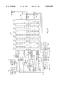
- FIG. 1 shows a block diagram of a prior art device 100, which can be implemented as either a pLSI device or an ispLSI device.
- device 100 comprises 24 generic logic blocks (GLBs) A0-A7, B0-B7, C0-C7 and D0-D7.
- GLB generic logic blocks
- Each GLB includes a number of input terminals, a logic array for implementing logic functions and a number of output terminals.
- the signals at the GLB's input terminals originate either from the routing pool 101, or directly from input/output (I/O) pins, which are shown in FIG. 1 along the periphery of the device, e.g. I/O pin 102a.
- I/O input/output
- the signals of the output terminals of a GLB can be routed to both output routing pool 103 and routing pool 101.
- Output routing pool 103 routes signals between a group of GLBs and a group of I/O pins.
- Each I/O pin of pLSI device 100 is associated with an input/output cell ("I/O cell"), which is programmable to define whether the I/O pin is an input pin, an output pin or a bidirectional pin.
- Routing pool 101 is an interconnection resource for interconnection among the GLBs. Routing pool 101 receives input signals from both the I/O pins and the output terminals of the GLBs and provides the signals received to the input terminals of the GLBs. Routing pool 101 provides connectivity between any pair of GLBs in pLSI device 100.
- FIG. 1 four groups of GLBs A0-A7, B0-B7, C0-C7 and D0-D7 are shown.
- the signal received at each I/O cell is routed to one input terminal of routing pool 101.
- two additional input pins are provided per megablock to receive two additional signals into global routing pool.
- the GLBs implement all logic functions on the programmable logic device. While the GLBs are extremely flexible, memory elements, such as registers and random access memories, cannot be readily configured in a programmable logic device. Further, many frequently encountered logic circuits, although configurable in the GLBs, can be more efficiently provided in a custom circuit, which provides both efficiency in silicon area and speed.
- a programmable logic device having a plurality of programmable logic blocks and one or more application-specific blocks.
- a programmable logic block typically includes a fixed number of logic gates, and a fixed number of input and output terminals coupled to input/output pins, which are configured by a configuration circuit to implement a logic function.
- This invention provides an application-specific circuit within the programmable logic device for performing a predetermined logic function.
- the application-specific circuit can have a fixed number of input and output terminals coupled to the input and output pins of the programmable logic device.
- the programmable logic device provides a programmable interconnection resource for programmably interconnecting the programmable logic blocks and the application specific circuit.
- In-system programming capability can be provided in the programmable logic array.
- the present invention can be implemented using either volatile or non-volatile memory technology.
- the programmable interconnection resource comprises a switch matrix of interconnection lines.
- a programmable interface interconnection block is provided between the application-specific circuit and the programmable interconnection resource.
- the programmable interface interconnection block multiplexes each of the input and output terminals of the application-specific circuit onto one or more interconnection lines of the switch matrix.
- the application-specific circuit further includes a gate array to programmably multiplex input signals received from the switch matrix.
- the application-specific circuit includes a configuration circuit to allow the application-specific circuit to be configured into one of numerous configurations.
- the application-specific circuit includes a dual-port memory array, which is configurable as to both word size and total array size.
- the memory array can be programmably subdivided into one or more memory arrays.
- a control circuit in that embodiment provides for accessing the memory words of the dual-port memory array in a first-in-first-out manner.
- the control circuit includes read and write counter for generating addresses for accessing the memory array.
- a status signal logic circuit indicates qualitatively the amount of valid data in said memory array.
- the application-specific circuit comprises a plurality of registers of programmable sizes. These registers can be independently configured to have parallel or serial input data signals, parallel or serial input data signals, or other variations of these input and output data signals.
- the application-specific circuit in that embodiment can be configured to implement (i) a shift register of programmable sizes, one or more counters, or one or more timers.
- FIG. 1 shows a prior art programmable logic device having a plurality of generic logic blocks (GLBs) for configurating logic circuits.
- GLBs generic logic blocks
- FIGS. 2a-2d show embodiments of the present invention in which a programmable logic device 200 is provided with application-specific modules 209a and 209b, in accordance with the present invention.
- FIG. 3 shows global routing pool (GRP) 201 interconnecting local routing pools (LRPs) 202a and 202b.
- GRP global routing pool
- FIG. 4a is a block diagram of an ASB 400 suitable for implementing ASB 209a of FIG. 2a.
- FIG. 4b is a block diagram of memory circuit 420 of FIG. 4a.
- FIG. 4c shows AND arrays 470 and 471 providing the two groups A0 and A1 of interconnect lines routing signals from an LRP to ASB 400 under either an SRAM configuration or a FIFO memory configuration of ASB 400.
- FIG. 4d shows an interface interconnection block (IIB) 490 routing the output signals of ASB 400 into an LRP.
- IIB interface interconnection block
- FIG. 5a is a block diagram of an ASB 500 suitable for implementing ASB 209b of FIG. 2a.
- FIGS. 5b(i)-5b(vi) show the various possible configurations of ASB 500.
- FIG. 5c shows AND arrays 570 and 571 providing the two groups A0 and A1 of interconnect lines routing signals from an LRP to ASB 500 under.
- FIG. 5d shows an interface interconnect block (IIB) 590 routing the output signals of ASB 500 into an LRP.
- IIB interface interconnect block
- FIG. 6a shows a circuit 600 suitable for implementing one of ASB 500's register banks 0, 2, 4, and 6.
- FIG. 6b shows a circuit 650 suitable for implementing one of ASB 500's register banks 1, 3, 5, and 7.
- FIG. 2a shows, in one embodiment of the present invention, a block diagram of a programmable logic device 200 including 6 "megablocks" 203a-203l and two application-specific modules ("ASBs") 203a and 203b. Each megablock includes four generic logic blocks (“GLBs”), an output routing pool, and 16 I/O cells.
- programmable logic device 200 includes a clock distribution structure 206 (not shown), two local routing pools (“LRP”) 202a and 202b, and a global routing pool (“GRP”) 201.
- LRP local routing pools
- GRP global routing pool
- LRP 202a provides connectivity among megablock 203a-203c and the interface interconnect block ("IIB") 208
- LRP 202b provides connectivity among megablocks 203d-203f and IIB 208
- GRP 201 provides connectivity between LRPs 202a and 202b.
- the hierarchical routing scheme i.e. the use of local and global routing pools, are discussed in detail in U.S. patent application Ser. No. 08/115,723, entitled “Structure and Method for Implementing Hierachical Routing Pools in a Programmable Logic Device," by C. Tsui et al, filed on Sep. 1, 1993, now U.S. Pat. No. 5,394,033 issued on Feb. 28, 1995, assigned to Lattice Semiconductor Corporation, which is also the Assignee of the present invention.
- the disclosure of application Ser. No. 08/115,723 is hereby incorporated by reference in its entirety.
- Clock distribution network 206 receives five external clock signals on five dedicated clock pins.
- the GLBs can also be configured to generate additional signals as clock input signals to clock distribution network 206.
- Five clock signals (three clock signals generated in the logic blocks, e.g. GLBs or ASBs, and two clock signals received from the I/O cells) can be distributed from clock distribution network 206 to any GLB, ASB or I/O cell of programmable logic device 200.
- FIG. 2b shows a typical structure 250 of a GLB in programmable logic device 200.
- each GLB has 24 input terminals (collectively referred to as input terminals 257), eight output terminals O1-O7, and an AND array 256.
- Input terminals 257 carry signals to AND array 256 from the LRP (say, LRP 202a) which serves GLB 250.
- AND array 256 receives (a) output signals of GLBs served by LRP 202a, (b) output signals from I/O cells in the megablocks which includes GLBs served by LRP 202a, and (c) output signals received over GRP 201.
- the signals received over GRP 201 include output signals of GLBs served by LRP 202b, and output signals from I/O cells in the megablocks which includes the GLBs served by LRP 202b.
- AND array 256 also receives four internal "fast feedback" signals from the product-term sharing arrays ("PTSAs") 251a and 251b of GLB 250.
- PTSAs product-term sharing arrays
- AND array 256 generates 2 groups of twenty product-term signals. Each product-term signal, which is provided both in logic true and the complement forms, is a logic product involving any number of the input signals received into AND array 256. In FIG. 2b, a first group of twenty product term signals is received by PTSA 251a, and a second group of twenty product term signals is received by PTSA 251b.
- Product-term sharing arrays such as product term sharing arrays 251a and 251b, are discussed in detail in U.S. Pat. No. 5,130,574, entitled "Programmable Logic Device Providing Product Term Sharing and Steering to the Outputs of the Programmable Logic Device," to J. Shen et al, filed on May 6, 1991, issued on Jul. 14, 1992, and assigned to Lattice Semiconductor Corporation.
- U.S. Pat. No. 5,130,574 is hereby incorporated by reference in its entirety.
- Output stage 252a includes output logic macrocells providing various programmable logic functional capabilities for generating either a registered or a combinatorial output signals of PTSA 251a. This type of logic macrocells used in output stage 252a are discussed in detail in U.S. Pat. No. 5,191,243, entitled “Output Logic Macrocell with Enhanced Functional Capabilities,” to J. Shen et al, filed on May 6, 1991 and issued on Mar. 2, 1993. U.S. Pat. No. 5,191,243 is hereby incorporated by reference in its entirety.
- output signals of multiplexer 253a-253d are provided as output signals O0-O3.
- Output signals O0-O3 are routed back to LRP 202a or, alternatively, via the output routing pool of GLB 250's megacell to the associated I/O cells.
- FIG. 2c shows output routing pool 204d, which serves megablock 203d of programmable logic device 200 (FIG. 2a).
- GLBs A0-A3 of megablock 203d are connected to a switch matrix 270.
- Switch matrix 270 receives from GLB A0-A3 their 32 output signals, and provides 16 output signals to I/O pins 205d-0 to 205d-15.
- Each of the 32 output signals of GLB A0-A3 is routed to four I/O cells. These I/O cells can each be independently configured as an input pin, an output pin, or a bidirectional pin. When configured as an input pin, the input signal received is routed via bus 271 to LRP 202b.
- each GLB four output terminals are each provided a programmable bypass signal path to an I/O cell. These bypass connections are shown in FIG. 2d.
- LRP 202a and LRP 202b are interconnection resources serving megablocks 203a-203f and IIB 208.
- IIB 208 is, in turn, a routing resource for routing output signals of ASB 209a and 209b to LRP 202a, as shown in FIG. 2a.
- Input signals to ASB 209a and 209b can be routed from LRP 202a directly into ASB 209a and 209b.
- FIG. 3 is a block diagram of a structure 300 implementing LRP 202a, LRP 202b, and GRP 201. As shown in FIG.
- each LRP has (i) 96 input terminals, collectively indicated by reference numeral 302a or 302b, receiving input signals from the I/O cells associated with the GLBs served by the LRP, (ii) 192 input terminals, collectively indicated by reference numeral 301a or 301b, receiving input signals from the eight output signals from the ASBs and the GLBs served by the LRP, (iii) 96 input terminals, collectively indicated by reference numeral 303a or 303b, for receiving from GRP 201 signals which originate from the other LRP, and (iv) 192 output terminals, collectively indicated by reference numeral 305a or 305b, for routing each of the 288 input signals received by the LRP to 96 of the input terminals of the ASBs and GLBs served by the LRP.
- LRP 202a and 202b are each implemented according to the interconnect structure discussed in U.S. Pat. No. 5,204,556, entitled “Programmable Interconnect Structure for Logic Blocks,” by Kapil Shankar, filed May 6, 1991, issued Apr. 26, 1993 and assigned to Lattice Semiconductor Corporation, which is the Assignee of the present application.
- U.S. Pat. No. 5,204,556 is hereby incorporated by reference in its entirety.
- LRP 202a provides 96 output terminals to route signals through GRP 201 to LRP 202b.
- LRP 202b provides 96 output terminals to route signals through GRP 201 to LRP 202a.
- GRP 201 interconnects LRP 202a and 202b.
- the interconnections 305a and 305b are provided buffers, which are collectively indicated by reference numerals 304a and 304b respectively.
- Using GRP 201 to interconnect LRP 202a and 202b maintains connectivity between the GLBs and the ASBs served by LRP 202b and the GLBs and the ASBs served by LRP 202b, while routing only a fraction of total number of signals received by LRPs 202a and 202b. Consequently, significant reduction of silicon area is achieved.
- Structure 300 can be optimally used by preferentially implementing interconnected logic circuits in GLBs served by the same LRP, thereby reducing the number of signals required to be transmitted between LRPs via GRP 201.
- signals between GLBs, or between a GLB and an ASB are transmitted over an LRP, which is a smaller interconnection circuit than the alternative under a single routing pool system.
- LRP 202a and LRP 202b, and GRP 201 are each regular in structure, so that signal delays within each LRP, or over GRP 201, remain predictable and consistent.
- ASB 209a and 209b are respectively a memory module and a register module.
- ASB 209a can be configured as one of the following: (i) a single-port static random access memory (SRAM), (ii) two single-port SRAMs, (iii) a dual-port SRAM, and (iv) a first-in-first-out (FIFO) memory.
- FIG. 4a is a block diagram of an ASB 400 suitable for implementing memory module ASB 209a of FIG. 2a.
- ASB 400 has a memory circuit 420 which can be accessed from two ports "A" and "B".
- ASB 400's memory array can be organized either as a 512 ⁇ 9 or a 256 ⁇ 18 memory array.
- Ports A and B of ASB 400 each comprise 18 data I/O signals, 8 address signals, a busy signal, a chip select signal, and and two read/write control signals.
- the address signals are primarily used when ASB 400 is configured as SRAMs. When configured as a FIFO memory, four status signals “full”, “almost full”, “empty”, and “almost empty” are generated by ASB 400. A reset signal is also received by ASB 400 when it is configured as a FIFO memory.
- Port A is accessible from the I/O pins of the programmable device.
- I/O cells 0-17 form an 18-bit data bus accessible through 18 corresponding pins of the programmable logic device.
- An output enable signal which is either generated in a GLB or received as a global output enable signal, is provided to I/O cell 0 from one of two groups A0 and A1 of interconnection lines receiving signals from an LRP (A0 and A1 are output lines of two AND arrays 470 and 471, described below, used for routing the signals lines of the LRP into ASB 400).
- Output enable signals for programmable logic device 200 are discussed in a application Ser. No.
- bus 412a carries the input signals received at I/O cells 0-17 to memory circuit 420 as data input signals. Data output signals provided by memory circuit 420 are routed to I/O cells 0-17 by bus 410a.
- ASB 400 can also be configured to have either a 9-bit data path or a 18-bit data path. When a 9-bit data path is desired, I/O cells 9-17 can be used for other input/output purposes.
- a busy signal generated by ASB 400 indicates a "busy" port A, when the memory cell sought to be accessed through port A is simultaneously accessed by a pending memory access at port B. This busy signal is routed to I/O cell 18 via lead 404a.
- I/O cells 19-26 form a 8-bit bus for receiving a memory address, which is routed to memory circuit 420 via bus 411a.
- I/O cell 19 receives a reset signal which is routed to memory circuit 420 on lead 421, and I/O cells 20-23 receive the four status signals "full”, “almost full”, “empty” and "almost empty” from memory circuit 420 via leads 406-409 respectively.
- Memory circuit 420 can also receive an internally generated reset signal, which is routed from the associated LRP into ASB 400 through group A0 of interconnect lines.
- ASB 400 can be programmed to select either the reset signal on lead 421 or the reset signal on lead 417 routed via the LRP.
- ASB 400 receives read/write control signals and a chip select signal respectively from either (i) I/O cells 27-29, over leads 413c, 414c, and 415c, or (ii) the LRP, via leads 413a, 414a, and 415a.
- the output signals of memory circuit 420 are routed to an IIB 490, which provides an interface into an LRP.
- These output signals of memory circuit 420 are the data output signals of port B (bus 410), busy signals for ports A and B (leads 404a and 404b, respectively), "full” signal (lead 406), “almost full” signal (lead 407), “almost empty” signal (lead 408), and "empty” signal (lead 409).
- the I/O signals of port B of memory circuit 420 are similar to the I/O signals of port A. However, since the signals at port B are routed through the LRP, the signals at port B can be coupled to the GLBs of programmable logic device 200. Memory circuit 420 can therefore be used to support the logic functions implemented in the GLBs. Thus, memory circuit 420 provides an effective on-chip memory for many applications.
- FIG. 4b shows an implementation of memory circuit 420 of FIG. 4a.
- memory circuit 420 comprises a dual-port SRAM 425, which is accessed either from port A or port B.
- multiplexers 440, 442, and 443 are programmed to select (i) the port A address signals of bus 452, (ii) the read/write control signal on lead 451, and a chip select signal on lead 450.
- the address signals on bus 452 are the signals shown in FIG. 4a on bus 411a.
- the read/write control signal on bus 451 can be one of the read/write control signals of leads 413a, 413c, 414a or 414c of FIG. 4a.
- ASB 400 also selects whether ASB 400 has a 9-bit data path or an 18-bit data path at the I/O pins. Selection of data path width is accomplished by multiplexer 430, which routes the data input/output signals of dual-port SRAM 425 to the 18-bit data path (busses 460 and 461), or the 9-bit data path (either bus 460 or 461, as detemined by the programming of programmable logic device 200).
- the chip select signal on lead 450 can be the signal on either lead 415c or 415a of FIG. 4a.
- the port B signals under an SRAM configuration of ASB 400 are provided in a manner similar to that described above with respect to port A signals.
- a busy signal for one port is generated whenever a later arriving memory access at that port attempts to access the same memory address as the memory address being then accessed at the other port.
- the busy signal is generated by arbitration logic circuit 429, which compares addresses at port A and port B whenever the chip select signals at both ports A and B are asserted.
- the busy signal at port A is asserted when the chip select signal at port A is later than the chip select signal at port B, and vice versa.
- each SRAM is either 128 ⁇ 18-bit or 256 ⁇ 9-bit.
- multiplexers 441 and 437 fixes bit 7 of the addresses presented at ports A and B to opposite values.
- ASB 400 When ASB 400 is configured as a FIFO memory, one of ports A and B is selected to be the "read" port (i.e. output port) of the FIFO memory, and the other port is selected to be the write port (i.e. input port) of the FIFO memory.
- Read counter 427 generates the read address of the FIFO memory. This read address is routed by multiplexers 432 or 433 to either multiplexer 436 (port B) or multiplexer 440 (port A).
- write counter 428 generates the write address of the FIFO memory. The write address of the FIFO memory is routed by multiplexers 432 or 433 to either multiplexer 436 (port B) or multiplexer 440 (port A).
- Flag control logic circuit 426 detects the "full”, “empty”, “almost empty” and “almost full” conditions. The “almost full” and “almost empty” conditions are each generated when the number of valid data stored in the FIFO memory reaches the programmable threshold for the respective condition.
- FIG. 4c shows AND arrays 470 and 471 providing the two groups A0 and A1 of interconnect lines routing signals from an LRP to ASB 400 under both an SRAM configuration and a FIFO memory configuration of ASB 400.
- the assignments of the interconnect lines in the groups A0 and A1 under each configuration are shown in the respective columns on the left of each AND array.
- FIG. 4d shows an interface interconnect block (IIB) 490 routing the output signals of ASB 400 into an LRP. As shown in FIG. 4d, each input signal to IIB 490 can be routed to one of four LRP lines.
- IIB interface interconnect block
- FIG. 5a is a block diagram of ASB 500 which can be used to implement ASB 209b of FIG. 2a.
- ASB 500 can be configured as (i) a register file of up to eight registers; (ii) a counter bank of up to four counters; (iii) a timer bank of up to four modulo counters ("timers"); and (iv) a shift register.
- ASB 500 can be configured to form a shift register of one of many lengths.
- ASB 500 can be a serial input and serial output shift register, a serial input and parallel output shift register, or a parallel input and serial output shift register.
- ASB 500 comprises eight banks 501a-501f of registers, which can each be configured to be 4, 8, 12 or 16 bits wide.
- ASB 500 receives input signals on two groups A0 and A1 of interconnection lines from two AND arrays 570 and 571, and from I/O pins of programmable logic device 200.
- ASB 500 provides output signals to both an associated LRP, via an interface interconnection block (IIB) 590, and I/O pins of programmable logic device 200.
- IIB interface interconnection block
- block 502 contains a logic circuit for selecting an output enable signal to be used in the I/O cells of ASB 500.
- the I/O cells of ASB 500 associate selected input and output signals of ASB 500 with the I/O pins of programmable logic device 200.
- block 502 can be configured to select an output enable signal from two global output enable signals and a product term output enable signal.
- I/O cell 503 receives an enable signal from an I/O pin.
- This enable signal which is provided on lead 513 and routed to register banks 501a-501h by configuring multiplexer 514, parallel loads a selected register the data received on the I/O pins associated with I/O cells 505a-505p.
- I/O cell 504 receives a serial input signal at an associated I/O pin. This serial input signal, which is provided on lead 512, is routed to register banks 501a-501h by configuring multiplexer 516.
- I/O cells 505a-505p can be used to configured the associated I/O pins as input pins, output pins or bidirectional pins for parallel data input and/or output for ASB 500.
- Input signals received at the I/O pins associated with I/O cells 505a-505p are provided on internal data bus 511.
- output signals provided on the I/O pins associated with I/O cells 505a-505p are received from internal data bus 509.
- ASB 500 is configured to provide serial output
- I/O cell 506 provides a serial output signal at an associated I/O cell.
- I/O cell 507 provides up to four "count carry out" or "terminal count” signals.
- the "count carry out” signals can be used to cascade ASBs of multiple programmable logic devices to form larger counters.
- timer mode when a timer reaches a predetermined count value, a terminal count signal is asserted.
- the output signals of register banks 501a-501h (specifically, serial output signal 508, parallel data output bus 509 and count carry out signals 510) are also provided to IIB or "premux" 590 for routing to an associated LRP.
- one of register banks 501a-501h is selected by demultiplexer 517, according to the value of a 3-bit signal received on the A0 group of interconnection lines.
- the A0 group of interconnection lines also provides a serial input signal and a parallel load enable signal, which can be selected, by suitably configuring multiplexers 516 and 514, in place of the serial input signal on lead 513 and the parallel load enable signal 512 received from the I/O pins.
- group A0 provides: (a) a "shift enable" signal on lead 518 for serial input or output, (b) under counter or timer mode, four "pre-load” signals on bus 519 for parallel loading of counters, (c) four "carry in” or “count hold” signals on bus 520 (in counter mode, "carry in” signals; in timer mode, "count hold” control signals); and (d) a product term clock signal on lead 521.
- each asserted "carry in” signal causes an associated counter to increment or decrement in the next clock period.
- each "count hold” signal prevents the associated timer from incrementing or decrementing the count in the timer during the next clock period.
- the embodiment of FIG. 5a can be configured to use one of the 5 clock signals: any one of three global clock signals, a clock signal received from an I/O cell, or a product term clock signal generated by internal logic.
- FIGS. 5b(i)-5b(vi) show the various configurations of ASB 500.
- FIG. 5b(i) shows ASB 500 being configured for parallel data input and parallel data output on busses 523 and 509, respectively.
- 3-bit select lines 524 select which of the eight 16-bit register banks is addressed.
- the enable signal on lead 525 enables the data on bus 523 to be written into the selected register bank.
- the input bus 523 can be configured to provide true or complement logic format. Complement format is provided by inverted the input signals received from I/O cells 505a-505p by multiplexer 515, or by selecting the inverted output of AND array 570.
- FIG. 5b(ii) shows ASB 500 being configured for parallel data input and both parallel and serial data output.
- two or more adjacent register banks can be configured to form a shift register of any size between 20-128 bits, at 4-bit increments.
- the shift register can be 4-bit, 8-bit, 12-bit or 16-bit.
- each register bank can be read or loaded in parallel in substantially the same manner as described above with respect to the configuration shown in FIG. 5b(i).
- the register bank at the most significant end of the shift register can be configured to be a 4-bit, 8-bit, 12-bit or 16-bit shift register slice, with the shift register's remaining register banks each set to be 16-bit wide.
- the shift enable signal on lead 518 when the shift enable signal on lead 518 is asserted, the bits in the shift register are shifted one bit per clock cycle, with the least significant bit shifted out of the shift register onto serial output lead 508.
- priority is given to the enable signal on lead 525, i.e. if both the enable signal on lead 525 and the shift enable signal on lead 518 are asserted, parallel data load of a selected register bank results.
- FIG. 5b(iii) shows ASB 500 being configured for both parallel and serial data input and parallel data output.
- two or more adjacent register banks can be configured to form a shift register of any size between 20-128 bits, at 4-bit increments.
- the shift register can be 4-bit, 8-bit, 12-bit or 16-bit.
- the register bank at the most significant end of the shift register can be configured as a 4-bit, 8-bit, 12-bit or 16-bit shift register slice, with the shift register's remaining register banks each set to be 16-bit wide.
- Parallel data read and data write are carried out in substantially the same manner as described above with respect to the configuration of FIG. 5b(i).
- the enable signal on lead 525 has priority over the shift enable signal on lead 518.
- FIG. 5b(iv) shows ASB 500 configured for both parallel and serial data input and both parallel and serial data output.
- two or more adjacent register banks can be configured to form a shift register of any size between 20-128 bits, at 4-bit increment.
- the register bank at the most significant end of the shift register can be configured to be a 4-bit, 8-bit, 12-bit or 16-bit shift register slice, with the shift register's remaining register banks each set to be 16-bit wide.
- the shift register can be 4-bit, 8-bit, 12-bit or 16-bit.
- the shift enable signal on lead 518 When the shift enable signal on lead 518 is asserted, the bit on lead 523 is shifted into the shift register as the most significant bit, and the least significant bit shifted out of the shift register onto lead 508 as a serial data output bit.
- the enable signal on lead 525 has priority over the shift enable signal on lead 518.
- FIG. 5b(v) shows ASB 500 being configured for counter operations.
- counter functions are provided only in register banks 1, 3, 5 and 7.
- ASB 500 can be configured into four 4-, 8-, 12-, or 16-bit counters.
- two or more adjacent register banks can be configured to form a larger up/down counter of any size between 20-64 bits, at 4-bit increments.
- the register bank at the most significant end is configured as a 4-bit, 8-bit, 12-bit or 16-bit counter, with the larger counter's remaining register banks eacg set at 16 bits wide. In this configuration, when the enable signal on lead 525 is asserted, the selected register bank is loaded in parallel.
- the selected counter loads the content of an adjacent register bank. For example, when the signal on lead 519 is asserted, the counter in register bank 1 loads in parallel the content of register bank 0.
- a count "carry in” signal on bus 520 is asserted, depending on whether the counter associated with this count "carry in” signal is programmed to be an up counter or a down counter, the associated counter is incremented or decremented. Also, depending on whether the counter is programmed to be an up counter or a down counter, overflow or underflow condition in each counter is indicated in the corresponding "carry out" signal on bus 510.
- FIG. 5b(vi) shows ASB 500 being configured for timer operations.
- a timer is a counter which does not "wrap" around when the terminal count is reached.
- only register banks 1, 3, 5 and 7 can provide with timer functions.
- two or more adjacent timers in ASB 500 can be configured to form a timer of any width between 20-64 bits, at 4-bit increments.
- each timer in ASB 500 can be individually configured as a 4, 8, 12 or 16-bit timer.
- a preset value can be specified for each timer. When the start signal on lead 518 is set to logic load, the preset value is loaded into the selected counter to perform the timer operations.
- FIG. 5c shows AND arrays 570 and 571 providing the two groups A0 and A1 of interconnect lines routing signals from an LRP to ASB 500.
- the assignments of the interconnect lines in the groups A0 and A1 are shown in the column on the left of each AND array.
- FIG. 5d shows an interface interconnect block (IIB) 590 routing the output signals of ASB 500 into an LRP. As shown in FIG. 5d, each input signal to IIB 590 can be routed to one of four LRP lines.
- IIB interface interconnect block
- FIG. 6a shows a circuit 600 suitable for implementing one of the register banks 0, 2, 4 and 6 in the present embodiment.
- a 16-bit register 601 comprising sixteen D-type flip-flops provides the storage capacity in a register bank.
- the 16 output signals on bus 602 can be provided to both the common output leads of the register banks (i.e. bus 509 of FIG. 5a) and the input leads of next higher register bank (i.e. if circuit 600 implements register bank 0, the output leads of circuit 600 provides input signals to the input leads of register bank 1).
- Bus 602 also provides input signals to shift logic block 610.
- Shift logic block 610 selects as a "serial-in" bit one of (a) the least significant bit on lead 603 from the previous register bank and (b) the signal on lead 523 (FIG. 5a), which is a common serial input pin of the register banks. Under a shift operation, the serial-in bit is inserted at an appropriate 4-bit boundary to the value on output bus 602. For example, if the present register bank is configured as a 12-bit shift register, the serial bit is inserted by multiplexer 605a into bit 11 of the value on bus 602, resulting in the shifted value on bus 606. The remaining 11 bits (i.e.
- bits 0-11) of the value on bus 606 are obtained by shifting bits 0-11 of bus 602 using the shifters 604b, 604c, and 604d, with multiplexers 605b and 605c set to receive bits 8 and 4 of bus 602 respectively.
- the input signals to register 601 are selected by multiplexer 607 from three sources: (a) bus 602, (b) bus 606 and (c) bus 522.
- the signals of bus 602 are selected when neither the shift enable signal on lead 518, nor the enable signal on lead 525, is asserted.
- the signals of bus 606 are selected when the shift enable signal on lead 518 is asserted, and the signals on bus 522 are selected when the enable signal on lead 525 is asserted.
- gates 611 and 612 ensures that the enable signal on lead 525 has priority over the shift enable signal on lead 518.
- the clock signal for register 601 is selected from five sources by multiplexer 613. From the clock signal selected by multiplexer 613, multiplexer 614 further selects one of two phases. A global reset signal provided on lead 615 initializes register 601.
- FIG. 6b shows a circuit 650 suitable for implementing one of the register banks 1, 3, 5 and 7 in the present embodiment.
- FIGS. 6a and 6b like elements in circuits 600 and 650 are provided the same reference numerals.
- 16-bit register 601, shift logic 610, and multiplexers 613 and 614 for clock signal selection are substantially identical in both circuits 600 and 650.
- register 601 in addition to receiving input signals from data bus 522, bus 602 and shift bus 606, register 601 can receive from two additional sources of input signals through multiplexer 651. These two additional sources of input signals are the "preload data" on bus 654, and the next count signals on bus 656. The next count signals of bus 656 are the output signals from counter logic 670.
- Multiplexer 662 selects for preload data bus 654 either the 16-bit data of the previous register bank's output signals received on bus 603, or a preset value configured at programming time by setting multiplexers 655.
- Multiplexers 655 include 16 two-to-one multiplexers, which are each independently programmed to provide a 16-bit value. The data on bus 654 is selected when the "preload" signal on lead 519a (a bit on bus 519 of FIG. 5a) is asserted.
- the "next count” signals on bus 656 are selected when circuit 650 is in either the counter or the timer mode. Depending upon whether multiplexer 657 selects for bus 675 the signals on bus 602, or their complement signals, count logic 670 implements either an up-counter or a down-counter. When the count "carry in” signal on input lead 520a (a bit of bus 520, shown in FIG. 5a) is asserted, incrementer 658 increments the output value from multiplexer 657, and provides on bus 656 as its output value the 16-bit next count signals. Circuit 661 detects the appropriate overflow or underflow condition (i.e.
- the bits on bus 675 are all "one's"), and provide a "count carry out” signal on lead 510a (a bit of bus 510 in FIG. 5a).
- the count "carry out” signal becomes the "terminal count” signal.
- gate 660 selects as output signals of multiplexer 659 the signals on bus 602 as the “next count” signals.
Abstract
Description
Claims (41)
Priority Applications (1)
| Application Number | Priority Date | Filing Date | Title |
|---|---|---|---|
| US08/827,671 US5835405A (en) | 1993-12-13 | 1997-04-10 | Application specific modules in a programmable logic device |
Applications Claiming Priority (3)
| Application Number | Priority Date | Filing Date | Title |
|---|---|---|---|
| US16648393A | 1993-12-13 | 1993-12-13 | |
| US48231695A | 1995-06-06 | 1995-06-06 | |
| US08/827,671 US5835405A (en) | 1993-12-13 | 1997-04-10 | Application specific modules in a programmable logic device |
Related Parent Applications (1)
| Application Number | Title | Priority Date | Filing Date |
|---|---|---|---|
| US48231695A Continuation | 1993-12-13 | 1995-06-06 |
Publications (1)
| Publication Number | Publication Date |
|---|---|
| US5835405A true US5835405A (en) | 1998-11-10 |
Family
ID=22603498
Family Applications (1)
| Application Number | Title | Priority Date | Filing Date |
|---|---|---|---|
| US08/827,671 Expired - Lifetime US5835405A (en) | 1993-12-13 | 1997-04-10 | Application specific modules in a programmable logic device |
Country Status (5)
| Country | Link |
|---|---|
| US (1) | US5835405A (en) |
| EP (1) | EP0734573B1 (en) |
| JP (1) | JPH09509797A (en) |
| DE (1) | DE69430320T2 (en) |
| WO (1) | WO1995016993A1 (en) |
Cited By (88)
| Publication number | Priority date | Publication date | Assignee | Title |
|---|---|---|---|---|
| US6011730A (en) * | 1997-07-16 | 2000-01-04 | Altera Corporation | Programmable logic device with multi-port memory |
| US6018490A (en) * | 1991-09-03 | 2000-01-25 | Altera Corporation | Programmable logic array integrated circuits |
| US6020760A (en) * | 1997-07-16 | 2000-02-01 | Altera Corporation | I/O buffer circuit with pin multiplexing |
| US6049223A (en) * | 1995-03-22 | 2000-04-11 | Altera Corporation | Programmable logic array integrated circuit with general-purpose memory configurable as a random access or FIFO memory |
| WO2001024368A1 (en) * | 1999-09-29 | 2001-04-05 | Infineon Technologies Ag | Reconfigurable gate array |
| US6242946B1 (en) | 1996-04-15 | 2001-06-05 | Altera Corporation | Embedded memory block with FIFO mode for programmable logic device |
| US6259588B1 (en) | 1997-07-16 | 2001-07-10 | Altera Corporation | Input/output buffer with overcurrent protection circuit |
| US6262933B1 (en) | 1999-01-29 | 2001-07-17 | Altera Corporation | High speed programmable address decoder |
| US6288970B1 (en) * | 1997-10-16 | 2001-09-11 | Altera Corporation | Programmable logic device memory array circuit having combinable single-port memory arrays |
| US6300793B1 (en) | 1995-05-03 | 2001-10-09 | Btr, Inc. | Scalable multiple level tab oriented interconnect architecture |
| US6320412B1 (en) | 1999-12-20 | 2001-11-20 | Btr, Inc. C/O Corporate Trust Co. | Architecture and interconnect for programmable logic circuits |
| US6329839B1 (en) | 1996-09-04 | 2001-12-11 | Advantage Logic, Inc. | Method and apparatus for universal program controlled bus architecture |
| US6362997B1 (en) * | 2000-10-16 | 2002-03-26 | Nvidia | Memory system for use on a circuit board in which the number of loads are minimized |
| US20020070756A1 (en) * | 1995-05-03 | 2002-06-13 | Ting Benjamins S. | Floor plan for scalable multiple level tab oriented interconnect architecture |
| EP1220107A2 (en) * | 2000-10-26 | 2002-07-03 | Cypress Semiconductor Corporation | Programmable digital device |
| US20020130681A1 (en) * | 1991-09-03 | 2002-09-19 | Cliff Richard G. | Programmable logic array integrated circuits |
| US6462578B2 (en) | 1993-08-03 | 2002-10-08 | Btr, Inc. | Architecture and interconnect scheme for programmable logic circuits |
| US6463340B2 (en) * | 2000-06-08 | 2002-10-08 | Denno Co., Ltd. | Control system |
| US6467017B1 (en) | 1998-06-23 | 2002-10-15 | Altera Corporation | Programmable logic device having embedded dual-port random access memory configurable as single-port memory |
| US6486702B1 (en) | 1999-07-02 | 2002-11-26 | Altera Corporation | Embedded memory blocks for programmable logic |
| US6507217B2 (en) | 1993-08-03 | 2003-01-14 | Btr, Inc. | Architecture and interconnect scheme for programmable logic circuits |
| US20030062922A1 (en) * | 2001-09-28 | 2003-04-03 | Xilinx, Inc. | Programmable gate array having interconnecting logic to support embedded fixed logic circuitry |
| WO2003073620A1 (en) * | 2002-02-25 | 2003-09-04 | Xilinx, Inc. | Floor planning for programmable gate array having embedded fixed logic circuitry |
| US6624658B2 (en) | 1999-02-04 | 2003-09-23 | Advantage Logic, Inc. | Method and apparatus for universal program controlled bus architecture |
| WO2003105345A2 (en) * | 2002-06-10 | 2003-12-18 | Xilinx, Inc. | Programmable logic device having heterogeneous programmable logic blocks |
| US20040004496A1 (en) * | 2002-07-08 | 2004-01-08 | Madurawe Raminda U. | Field programmable gate array with convertibility to application specific integrated circuit |
| US20040018711A1 (en) * | 2002-07-08 | 2004-01-29 | Madurawe Raminda U. | Methods for fabricating three dimensional integrated circuits |
| US6718429B1 (en) * | 2000-08-22 | 2004-04-06 | Antevista Gmbh | Configurable register file with multi-range shift register support |
| US6720796B1 (en) | 2001-05-06 | 2004-04-13 | Altera Corporation | Multiple size memories in a programmable logic device |
| US6754882B1 (en) | 2002-02-22 | 2004-06-22 | Xilinx, Inc. | Method and system for creating a customized support package for an FPGA-based system-on-chip (SoC) |
| US6759870B2 (en) | 1991-09-03 | 2004-07-06 | Altera Corporation | Programmable logic array integrated circuits |
| US6772405B1 (en) | 2002-06-13 | 2004-08-03 | Xilinx, Inc. | Insertable block tile for interconnecting to a device embedded in an integrated circuit |
| US6781407B2 (en) | 2002-01-09 | 2004-08-24 | Xilinx, Inc. | FPGA and embedded circuitry initialization and processing |
| US20040196065A1 (en) * | 2002-07-08 | 2004-10-07 | Madurawe Raminda Udaya | Programmable devices with convertibility to customizable devices |
| US20040212395A1 (en) * | 2002-07-08 | 2004-10-28 | Madurawe Raminda Udaya | Three dimensional integrated circuits |
| US20040214387A1 (en) * | 2002-07-08 | 2004-10-28 | Madurawe Raminda Udaya | Methods for fabricating three dimensional integrated circuits |
| US20040222817A1 (en) * | 2002-07-08 | 2004-11-11 | Madurawe Raminda Udaya | Alterable application specific integrated circuit (ASIC) |
| US6820248B1 (en) | 2002-02-14 | 2004-11-16 | Xilinx, Inc. | Method and apparatus for routing interconnects to devices with dissimilar pitches |
| US6839874B1 (en) | 2002-02-28 | 2005-01-04 | Xilinx, Inc. | Method and apparatus for testing an embedded device |
| US20050040850A1 (en) * | 2001-09-28 | 2005-02-24 | Xilinx, Inc. | Programmable gate array and embedded circuitry initialization and processing |
| US20050058186A1 (en) * | 2003-09-11 | 2005-03-17 | Xilinx, Inc. | Channel bonding of a plurality of multi-gigabit transceivers |
| US6886092B1 (en) | 2001-11-19 | 2005-04-26 | Xilinx, Inc. | Custom code processing in PGA by providing instructions from fixed logic processor portion to programmable dedicated processor portion |
| US20050091630A1 (en) * | 2003-10-23 | 2005-04-28 | Madurawe Raminda U. | Programmable interconnect structures |
| US20050121789A1 (en) * | 2003-12-04 | 2005-06-09 | Madurawe Raminda U. | Programmable structured arrays |
| US20050149896A1 (en) * | 2004-01-05 | 2005-07-07 | Madurawe Raminda U. | Integrated circuits with RAM and ROM fabrication options |
| US20050162933A1 (en) * | 2002-10-21 | 2005-07-28 | Madurawe Raminda U. | Programmable interconnect structures |
| US20050181546A1 (en) * | 2002-07-08 | 2005-08-18 | Madurawe Raminda U. | Methods for fabricating fuse programmable three dimensional integrated circuits |
| US20050180044A1 (en) * | 2004-02-14 | 2005-08-18 | Samsung Electronics Co., Ltd. | Damping structure of a hard disk drive |
| US6934922B1 (en) | 2002-02-27 | 2005-08-23 | Xilinx, Inc. | Timing performance analysis |
| US20050218928A1 (en) * | 2004-03-30 | 2005-10-06 | Pani Peter M | Scalable non-blocking switching network for programmable logic |
| US6961919B1 (en) | 2002-03-04 | 2005-11-01 | Xilinx, Inc. | Method of designing integrated circuit having both configurable and fixed logic circuitry |
| US6973405B1 (en) | 2002-05-22 | 2005-12-06 | Xilinx, Inc. | Programmable interactive verification agent |
| US6976160B1 (en) | 2002-02-22 | 2005-12-13 | Xilinx, Inc. | Method and system for controlling default values of flip-flops in PGA/ASIC-based designs |
| US6983405B1 (en) | 2001-11-16 | 2006-01-03 | Xilinx, Inc., | Method and apparatus for testing circuitry embedded within a field programmable gate array |
| US20060023704A1 (en) * | 2004-07-29 | 2006-02-02 | Pani Peter M | Interconnection fabric using switching networks in hierarchy |
| US6996758B1 (en) | 2001-11-16 | 2006-02-07 | Xilinx, Inc. | Apparatus for testing an interconnecting logic fabric |
| US7007121B1 (en) | 2002-02-27 | 2006-02-28 | Xilinx, Inc. | Method and apparatus for synchronized buses |
| US7058920B2 (en) | 2001-05-06 | 2006-06-06 | Altera Corporation | Methods for designing PLD architectures for flexible placement of IP function blocks |
| US7076595B1 (en) | 2001-05-18 | 2006-07-11 | Xilinx, Inc. | Programmable logic device including programmable interface core and central processing unit |
| US7085973B1 (en) | 2002-07-09 | 2006-08-01 | Xilinx, Inc. | Testing address lines of a memory controller |
| US7088767B1 (en) | 2002-03-01 | 2006-08-08 | Xilinx, Inc. | Method and apparatus for operating a transceiver in different data rates |
| US7092865B1 (en) | 2002-09-10 | 2006-08-15 | Xilinx, Inc. | Method and apparatus for timing modeling |
| US7099426B1 (en) | 2002-09-03 | 2006-08-29 | Xilinx, Inc. | Flexible channel bonding and clock correction operations on a multi-block data path |
| US7111220B1 (en) | 2002-03-01 | 2006-09-19 | Xilinx, Inc. | Network physical layer with embedded multi-standard CRC generator |
| US7111217B1 (en) | 2002-02-28 | 2006-09-19 | Xilinx, Inc. | Method and system for flexibly nesting JTAG TAP controllers for FPGA-based system-on-chip (SoC) |
| US7187709B1 (en) | 2002-03-01 | 2007-03-06 | Xilinx, Inc. | High speed configurable transceiver architecture |
| US20070152708A1 (en) * | 2002-07-08 | 2007-07-05 | Madurawe Raminda U | MPGA products based on a prototype FPGA |
| US20070210826A1 (en) * | 2006-03-08 | 2007-09-13 | Madurawe Raminda U | Programmable logic devices comprising time multiplexed programmable interconnect |
| US20070283052A1 (en) * | 2006-06-02 | 2007-12-06 | Microchip Technology Incorporated | Dynamic Peripheral Function Remapping to External Input-Output Connections of an Integrated Circuit Device |
| US20080067594A1 (en) * | 2002-07-08 | 2008-03-20 | Madurawe Raminda U | Insulated-gate field-effect thin film transistors |
| US20080106953A1 (en) * | 2004-05-17 | 2008-05-08 | Madurawe Raminda U | Multi-port memory devices |
| US7423453B1 (en) | 2006-01-20 | 2008-09-09 | Advantage Logic, Inc. | Efficient integrated circuit layout scheme to implement a scalable switching network used in interconnection fabric |
| US20090128188A1 (en) * | 2007-11-19 | 2009-05-21 | Raminda Udaya Madurawe | Pad invariant FPGA and ASIC devices |
| US20090128189A1 (en) * | 2007-11-19 | 2009-05-21 | Raminda Udaya Madurawe | Three dimensional programmable devices |
| US20090129174A1 (en) * | 2007-11-19 | 2009-05-21 | Raminda Madurawe | Multi-port thin-film memory devices |
| US20090167349A1 (en) * | 2007-12-26 | 2009-07-02 | Raminda Madurawe | Programmable logic based latches and shift registers |
| US20090167347A1 (en) * | 2007-12-26 | 2009-07-02 | Nij Dorairaj | Using programmable latch to implement logic |
| US20090167348A1 (en) * | 2007-12-26 | 2009-07-02 | Nij Dorairaj | Programmable latch based multiplier |
| US20090167350A1 (en) * | 2007-12-26 | 2009-07-02 | Raminda Madurawe | Programmable logic based latches and shift registers |
| US20100327907A1 (en) * | 2009-06-24 | 2010-12-30 | Ting Benjamin S | Enhanced permutable switching network with multicasting signals for interconnection fabric |
| US8159265B1 (en) | 2010-11-16 | 2012-04-17 | Raminda Udaya Madurawe | Memory for metal configurable integrated circuits |
| US8159268B1 (en) | 2010-11-16 | 2012-04-17 | Raminda Udaya Madurawe | Interconnect structures for metal configurable integrated circuits |
| US8159266B1 (en) | 2010-11-16 | 2012-04-17 | Raminda Udaya Madurawe | Metal configurable integrated circuits |
| US8643162B2 (en) | 2007-11-19 | 2014-02-04 | Raminda Udaya Madurawe | Pads and pin-outs in three dimensional integrated circuits |
| US9087169B2 (en) | 2008-09-14 | 2015-07-21 | Raminda U. Madurawe | Automated metal pattern generation for integrated circuits |
| US9766650B2 (en) | 2000-10-26 | 2017-09-19 | Cypress Semiconductor Corporation | Microcontroller programmable system on a chip with programmable interconnect |
| US9843327B1 (en) | 2000-10-26 | 2017-12-12 | Cypress Semiconductor Corporation | PSOC architecture |
| US10698662B2 (en) | 2001-11-15 | 2020-06-30 | Cypress Semiconductor Corporation | System providing automatic source code generation for personalization and parameterization of user modules |
Families Citing this family (20)
| Publication number | Priority date | Publication date | Assignee | Title |
|---|---|---|---|---|
| US5883850A (en) * | 1991-09-03 | 1999-03-16 | Altera Corporation | Programmable logic array integrated circuits |
| US5815726A (en) * | 1994-11-04 | 1998-09-29 | Altera Corporation | Coarse-grained look-up table architecture |
| US5757207A (en) * | 1995-03-22 | 1998-05-26 | Altera Corporation | Programmable logic array integrated circuit incorporating a first-in first-out memory |
| IL116792A (en) * | 1996-01-16 | 2000-01-31 | Chip Express Israel Ltd | Customizable integrated circuit device |
| US6107822A (en) * | 1996-04-09 | 2000-08-22 | Altera Corporation | Logic element for a programmable logic integrated circuit |
| US5715197A (en) | 1996-07-29 | 1998-02-03 | Xilinx, Inc. | Multiport RAM with programmable data port configuration |
| US5825202A (en) * | 1996-09-26 | 1998-10-20 | Xilinx, Inc. | Integrated circuit with field programmable and application specific logic areas |
| DE19654595A1 (en) * | 1996-12-20 | 1998-07-02 | Pact Inf Tech Gmbh | I0 and memory bus system for DFPs as well as building blocks with two- or multi-dimensional programmable cell structures |
| US6150837A (en) * | 1997-02-28 | 2000-11-21 | Actel Corporation | Enhanced field programmable gate array |
| US5874834A (en) | 1997-03-04 | 1999-02-23 | Xilinx, Inc. | Field programmable gate array with distributed gate-array functionality |
| US6052327A (en) * | 1997-10-14 | 2000-04-18 | Altera Corporation | Dual-port programmable logic device variable depth and width memory array |
| US6191611B1 (en) | 1997-10-16 | 2001-02-20 | Altera Corporation | Driver circuitry for programmable logic devices with hierarchical interconnection resources |
| AU2348800A (en) | 1998-11-24 | 2000-06-13 | Innovasic, Inc. | Fully programmable and configurable application specific integrated circuit |
| US6586966B1 (en) | 2001-09-13 | 2003-07-01 | Altera Corporation | Data latch with low-power bypass mode |
| US6566906B1 (en) | 2001-09-18 | 2003-05-20 | Altera Corporation | Specialized programmable logic region with low-power mode |
| US6937062B1 (en) | 2001-09-18 | 2005-08-30 | Altera Corporation | Specialized programmable logic region with low-power mode |
| US7082592B1 (en) | 2003-06-16 | 2006-07-25 | Altera Corporation | Method for programming programmable logic device having specialized functional blocks |
| US7698358B1 (en) | 2003-12-24 | 2010-04-13 | Altera Corporation | Programmable logic device with specialized functional block |
| US7190190B1 (en) | 2004-01-09 | 2007-03-13 | Altera Corporation | Programmable logic device with on-chip nonvolatile user memory |
| US8044437B1 (en) * | 2005-05-16 | 2011-10-25 | Lsi Logic Corporation | Integrated circuit cell architecture configurable for memory or logic elements |
Citations (8)
| Publication number | Priority date | Publication date | Assignee | Title |
|---|---|---|---|---|
| JPS5755625A (en) * | 1980-09-22 | 1982-04-02 | Nippon Telegr & Teleph Corp <Ntt> | Programmable logic array |
| US4706216A (en) * | 1985-02-27 | 1987-11-10 | Xilinx, Inc. | Configurable logic element |
| US4831591A (en) * | 1985-07-08 | 1989-05-16 | Nec Corporation | Semiconductor memory capable of executing logical operation |
| US4855803A (en) * | 1985-09-02 | 1989-08-08 | Ricoh Company, Ltd. | Selectively definable semiconductor device |
| US4872137A (en) * | 1985-11-21 | 1989-10-03 | Jennings Iii Earle W | Reprogrammable control circuit |
| EP0410759A2 (en) * | 1989-07-28 | 1991-01-30 | Xilinx, Inc. | Configurable logic array and method |
| EP0509376A2 (en) * | 1991-04-17 | 1992-10-21 | Hitachi, Ltd. | Signal processing device |
| US5280202A (en) * | 1991-03-06 | 1994-01-18 | Quicklogic Corporation | Programmable application specific integrated circuit and logic cell therefor |
-
1994
- 1994-12-13 WO PCT/US1994/013909 patent/WO1995016993A1/en active IP Right Grant
- 1994-12-13 EP EP95904802A patent/EP0734573B1/en not_active Expired - Lifetime
- 1994-12-13 JP JP7516799A patent/JPH09509797A/en active Pending
- 1994-12-13 DE DE69430320T patent/DE69430320T2/en not_active Expired - Fee Related
-
1997
- 1997-04-10 US US08/827,671 patent/US5835405A/en not_active Expired - Lifetime
Patent Citations (8)
| Publication number | Priority date | Publication date | Assignee | Title |
|---|---|---|---|---|
| JPS5755625A (en) * | 1980-09-22 | 1982-04-02 | Nippon Telegr & Teleph Corp <Ntt> | Programmable logic array |
| US4706216A (en) * | 1985-02-27 | 1987-11-10 | Xilinx, Inc. | Configurable logic element |
| US4831591A (en) * | 1985-07-08 | 1989-05-16 | Nec Corporation | Semiconductor memory capable of executing logical operation |
| US4855803A (en) * | 1985-09-02 | 1989-08-08 | Ricoh Company, Ltd. | Selectively definable semiconductor device |
| US4872137A (en) * | 1985-11-21 | 1989-10-03 | Jennings Iii Earle W | Reprogrammable control circuit |
| EP0410759A2 (en) * | 1989-07-28 | 1991-01-30 | Xilinx, Inc. | Configurable logic array and method |
| US5280202A (en) * | 1991-03-06 | 1994-01-18 | Quicklogic Corporation | Programmable application specific integrated circuit and logic cell therefor |
| EP0509376A2 (en) * | 1991-04-17 | 1992-10-21 | Hitachi, Ltd. | Signal processing device |
Cited By (249)
| Publication number | Priority date | Publication date | Assignee | Title |
|---|---|---|---|---|
| US6897679B2 (en) | 1991-09-03 | 2005-05-24 | Altera Corporation | Programmable logic array integrated circuits |
| US20020130681A1 (en) * | 1991-09-03 | 2002-09-19 | Cliff Richard G. | Programmable logic array integrated circuits |
| US6018490A (en) * | 1991-09-03 | 2000-01-25 | Altera Corporation | Programmable logic array integrated circuits |
| US20040066212A1 (en) * | 1991-09-03 | 2004-04-08 | Altera Corporation | Programmable logic array integrated circuits |
| US6023439A (en) * | 1991-09-03 | 2000-02-08 | Altera Corporation | Programmable logic array integrated circuits |
| US6759870B2 (en) | 1991-09-03 | 2004-07-06 | Altera Corporation | Programmable logic array integrated circuits |
| US6064599A (en) * | 1991-09-03 | 2000-05-16 | Altera Corporation | Programmable logic array integrated circuits |
| US6134173A (en) * | 1991-09-03 | 2000-10-17 | Altera Corporation | Programmable logic array integrated circuits |
| US7142012B2 (en) | 1993-08-03 | 2006-11-28 | Btr, Inc. | Architecture and interconnect scheme for programmable logic circuits |
| US6989688B2 (en) | 1993-08-03 | 2006-01-24 | Btr, Inc. | Architecture and interconnect scheme for programmable logic circuits |
| US8289047B2 (en) | 1993-08-03 | 2012-10-16 | Actel Corporation | Architecture and interconnect scheme for programmable logic circuits |
| US6462578B2 (en) | 1993-08-03 | 2002-10-08 | Btr, Inc. | Architecture and interconnect scheme for programmable logic circuits |
| US7078933B2 (en) | 1993-08-03 | 2006-07-18 | Btr, Inc. | Architecture and interconnect scheme for programmable logic circuits |
| US6507217B2 (en) | 1993-08-03 | 2003-01-14 | Btr, Inc. | Architecture and interconnect scheme for programmable logic circuits |
| US6597196B2 (en) | 1993-08-03 | 2003-07-22 | Btr, Inc. | Architecture and interconnect scheme for programmable logic circuits |
| US6747482B2 (en) | 1993-08-03 | 2004-06-08 | Btr. Inc. | Architecture and interconnect scheme for programmable logic circuits |
| US20060076974A1 (en) * | 1993-08-03 | 2006-04-13 | Ting Benjamin S | Architecture and interconnect scheme for programmable logic circuits |
| US20060202717A1 (en) * | 1993-08-03 | 2006-09-14 | Ting Benjamin S | Architecture and interconnect scheme for programmable logic circuits |
| US6049223A (en) * | 1995-03-22 | 2000-04-11 | Altera Corporation | Programmable logic array integrated circuit with general-purpose memory configurable as a random access or FIFO memory |
| US6340897B1 (en) | 1995-03-22 | 2002-01-22 | Altera Corporation | Programmable logic array integrated circuit with general-purpose memory configurable as a random access or FIFO memory |
| US7009422B2 (en) | 1995-05-03 | 2006-03-07 | Btr, Inc. | Floor plan for scalable multiple level tab oriented interconnect architecture |
| US20020070756A1 (en) * | 1995-05-03 | 2002-06-13 | Ting Benjamins S. | Floor plan for scalable multiple level tab oriented interconnect architecture |
| US20060114023A1 (en) * | 1995-05-03 | 2006-06-01 | Ting Benjamin S | Floor plan for scalable multiple level tab oriented interconnect architecture |
| US6417690B1 (en) * | 1995-05-03 | 2002-07-09 | Btr, Inc. | Floor plan for scalable multiple level tab oriented interconnect architecture |
| US6300793B1 (en) | 1995-05-03 | 2001-10-09 | Btr, Inc. | Scalable multiple level tab oriented interconnect architecture |
| US7126375B2 (en) | 1995-05-03 | 2006-10-24 | Btr, Inc. | Floor plan for scalable multiple level tab oriented interconnect architecture |
| US6242946B1 (en) | 1996-04-15 | 2001-06-05 | Altera Corporation | Embedded memory block with FIFO mode for programmable logic device |
| US20060202716A1 (en) * | 1996-09-04 | 2006-09-14 | Pani Peter M | Method and apparatus for universal program controlled bus architecture |
| US7382156B2 (en) | 1996-09-04 | 2008-06-03 | Actel Corporation | Method and apparatus for universal program controlled bus architecture |
| US20110043248A1 (en) * | 1996-09-04 | 2011-02-24 | Pani Peter M | Method and apparatus for universal program controlled bus architecture |
| US6975138B2 (en) | 1996-09-04 | 2005-12-13 | Advantage Logic, Inc. | Method and apparatus for universal program controlled bus architecture |
| US6504399B2 (en) | 1996-09-04 | 2003-01-07 | Advantage Logic, Inc. | Method and apparatus for universal program controlled bus architecture |
| US7830173B2 (en) | 1996-09-04 | 2010-11-09 | Actel Corporation | Method and apparatus for universal program controlled bus architecture |
| US6329839B1 (en) | 1996-09-04 | 2001-12-11 | Advantage Logic, Inc. | Method and apparatus for universal program controlled bus architecture |
| US7915918B2 (en) * | 1996-09-04 | 2011-03-29 | Actel Corporation | Method and apparatus for universal program controlled bus architecture |
| US20040178822A1 (en) * | 1996-09-04 | 2004-09-16 | Pani Peter M. | Method and apparatus for universal program controlled bus architecture |
| US20080191739A1 (en) * | 1996-09-04 | 2008-08-14 | Pani Peter M | Method and apparatus for universal program controlled bus architecture |
| US6020760A (en) * | 1997-07-16 | 2000-02-01 | Altera Corporation | I/O buffer circuit with pin multiplexing |
| US6151258A (en) * | 1997-07-16 | 2000-11-21 | Quickturn Design Systems, Inc. | Programmable logic device with multi-port memory |
| US6259588B1 (en) | 1997-07-16 | 2001-07-10 | Altera Corporation | Input/output buffer with overcurrent protection circuit |
| US6219284B1 (en) | 1997-07-16 | 2001-04-17 | Altera Corporation | Programmable logic device with multi-port memory |
| US6285211B1 (en) | 1997-07-16 | 2001-09-04 | Altera Corporation | I/O buffer circuit with pin multiplexing |
| US6011730A (en) * | 1997-07-16 | 2000-01-04 | Altera Corporation | Programmable logic device with multi-port memory |
| US6011744A (en) * | 1997-07-16 | 2000-01-04 | Altera Corporation | Programmable logic device with multi-port memory |
| US6288970B1 (en) * | 1997-10-16 | 2001-09-11 | Altera Corporation | Programmable logic device memory array circuit having combinable single-port memory arrays |
| US6467017B1 (en) | 1998-06-23 | 2002-10-15 | Altera Corporation | Programmable logic device having embedded dual-port random access memory configurable as single-port memory |
| US6262933B1 (en) | 1999-01-29 | 2001-07-17 | Altera Corporation | High speed programmable address decoder |
| US6459303B1 (en) | 1999-01-29 | 2002-10-01 | Altera Corporation | High speed programmable address decoder |
| US6624658B2 (en) | 1999-02-04 | 2003-09-23 | Advantage Logic, Inc. | Method and apparatus for universal program controlled bus architecture |
| US6593772B2 (en) | 1999-07-02 | 2003-07-15 | Altera Corporation | Embedded memory blocks for programmable logic |
| US6486702B1 (en) | 1999-07-02 | 2002-11-26 | Altera Corporation | Embedded memory blocks for programmable logic |
| US6717436B2 (en) | 1999-09-29 | 2004-04-06 | Infineon Technologies Ag | Reconfigurable gate array |
| WO2001024368A1 (en) * | 1999-09-29 | 2001-04-05 | Infineon Technologies Ag | Reconfigurable gate array |
| US6320412B1 (en) | 1999-12-20 | 2001-11-20 | Btr, Inc. C/O Corporate Trust Co. | Architecture and interconnect for programmable logic circuits |
| US6463340B2 (en) * | 2000-06-08 | 2002-10-08 | Denno Co., Ltd. | Control system |
| US6718429B1 (en) * | 2000-08-22 | 2004-04-06 | Antevista Gmbh | Configurable register file with multi-range shift register support |
| US6496404B1 (en) * | 2000-10-16 | 2002-12-17 | Nvidia Corporation | Memory system for use on a circuit board in which the number of loads is minimized |
| US6362997B1 (en) * | 2000-10-16 | 2002-03-26 | Nvidia | Memory system for use on a circuit board in which the number of loads are minimized |
| EP1220107A2 (en) * | 2000-10-26 | 2002-07-03 | Cypress Semiconductor Corporation | Programmable digital device |
| US10261932B2 (en) | 2000-10-26 | 2019-04-16 | Cypress Semiconductor Corporation | Microcontroller programmable system on a chip |
| US10248604B2 (en) | 2000-10-26 | 2019-04-02 | Cypress Semiconductor Corporation | Microcontroller programmable system on a chip |
| US9766650B2 (en) | 2000-10-26 | 2017-09-19 | Cypress Semiconductor Corporation | Microcontroller programmable system on a chip with programmable interconnect |
| US9843327B1 (en) | 2000-10-26 | 2017-12-12 | Cypress Semiconductor Corporation | PSOC architecture |
| US10020810B2 (en) | 2000-10-26 | 2018-07-10 | Cypress Semiconductor Corporation | PSoC architecture |
| US10725954B2 (en) | 2000-10-26 | 2020-07-28 | Monterey Research, Llc | Microcontroller programmable system on a chip |
| US7058920B2 (en) | 2001-05-06 | 2006-06-06 | Altera Corporation | Methods for designing PLD architectures for flexible placement of IP function blocks |
| US8732646B2 (en) | 2001-05-06 | 2014-05-20 | Altera Corporation | PLD architecture for flexible placement of IP function blocks |
| US8407649B2 (en) | 2001-05-06 | 2013-03-26 | Altera Corporation | PLD architecture for flexible placement of IP function blocks |
| US8201129B2 (en) | 2001-05-06 | 2012-06-12 | Altera Corporation | PLD architecture for flexible placement of IP function blocks |
| US6720796B1 (en) | 2001-05-06 | 2004-04-13 | Altera Corporation | Multiple size memories in a programmable logic device |
| US9094014B2 (en) | 2001-05-06 | 2015-07-28 | Altera Corporation | PLD architecture for flexible placement of IP function blocks |
| US7584447B2 (en) | 2001-05-06 | 2009-09-01 | Altera Corporation | PLD architecture for flexible placement of IP function blocks |
| US20070255886A1 (en) * | 2001-05-18 | 2007-11-01 | Xilinx, Inc. | Programmable logic device including programmable interface core and central processing unit |
| US7406557B2 (en) | 2001-05-18 | 2008-07-29 | Xilinx, Inc. | Programmable logic device including programmable interface core and central processing unit |
| US7076595B1 (en) | 2001-05-18 | 2006-07-11 | Xilinx, Inc. | Programmable logic device including programmable interface core and central processing unit |
| US7266632B2 (en) | 2001-05-18 | 2007-09-04 | Xilinx, Inc. | Programmable logic device including programmable interface core and central processing unit |
| US20060236018A1 (en) * | 2001-05-18 | 2006-10-19 | Xilinx, Inc. | Programmable logic device including programmable interface core and central processing unit |
| US7420392B2 (en) | 2001-09-28 | 2008-09-02 | Xilinx, Inc. | Programmable gate array and embedded circuitry initialization and processing |
| US6798239B2 (en) | 2001-09-28 | 2004-09-28 | Xilinx, Inc. | Programmable gate array having interconnecting logic to support embedded fixed logic circuitry |
| US20030062922A1 (en) * | 2001-09-28 | 2003-04-03 | Xilinx, Inc. | Programmable gate array having interconnecting logic to support embedded fixed logic circuitry |
| US20050040850A1 (en) * | 2001-09-28 | 2005-02-24 | Xilinx, Inc. | Programmable gate array and embedded circuitry initialization and processing |
| US10698662B2 (en) | 2001-11-15 | 2020-06-30 | Cypress Semiconductor Corporation | System providing automatic source code generation for personalization and parameterization of user modules |
| US6996758B1 (en) | 2001-11-16 | 2006-02-07 | Xilinx, Inc. | Apparatus for testing an interconnecting logic fabric |
| US6983405B1 (en) | 2001-11-16 | 2006-01-03 | Xilinx, Inc., | Method and apparatus for testing circuitry embedded within a field programmable gate array |
| US7080300B1 (en) | 2001-11-16 | 2006-07-18 | Xilinx, Inc. | Testing a programmable logic device with embedded fixed logic using a scan chain |
| US7194600B2 (en) | 2001-11-19 | 2007-03-20 | Xilinx, Inc. | Method and apparatus for processing data with a programmable gate array using fixed and programmable processors |
| US6886092B1 (en) | 2001-11-19 | 2005-04-26 | Xilinx, Inc. | Custom code processing in PGA by providing instructions from fixed logic processor portion to programmable dedicated processor portion |
| US7539848B1 (en) | 2001-11-19 | 2009-05-26 | Xilinx, Inc. | Configurable logic fabric including two fixed logic processors with individual interface to receive availability signal from custom operation code configured processor |
| US6781407B2 (en) | 2002-01-09 | 2004-08-24 | Xilinx, Inc. | FPGA and embedded circuitry initialization and processing |
| US6820248B1 (en) | 2002-02-14 | 2004-11-16 | Xilinx, Inc. | Method and apparatus for routing interconnects to devices with dissimilar pitches |
| US6976160B1 (en) | 2002-02-22 | 2005-12-13 | Xilinx, Inc. | Method and system for controlling default values of flip-flops in PGA/ASIC-based designs |
| US6754882B1 (en) | 2002-02-22 | 2004-06-22 | Xilinx, Inc. | Method and system for creating a customized support package for an FPGA-based system-on-chip (SoC) |
| US7552415B2 (en) | 2002-02-22 | 2009-06-23 | Xilinx, Inc. | Method and system for creating a customized support package for an FPGA-based system-on-chip (SoC) |
| US6996796B2 (en) | 2002-02-22 | 2006-02-07 | Xilinx, Inc. | Method and system for creating a customized support package for an FPGA-based system-on-chip (SoC) |
| US20040225992A1 (en) * | 2002-02-22 | 2004-11-11 | Xilinx, Inc. | Method and system for creating a customized support package for an FPGA-based system-on-chip (SoC) |
| US6693452B1 (en) | 2002-02-25 | 2004-02-17 | Xilinx, Inc. | Floor planning for programmable gate array having embedded fixed logic circuitry |
| WO2003073620A1 (en) * | 2002-02-25 | 2003-09-04 | Xilinx, Inc. | Floor planning for programmable gate array having embedded fixed logic circuitry |
| US7007121B1 (en) | 2002-02-27 | 2006-02-28 | Xilinx, Inc. | Method and apparatus for synchronized buses |
| US6934922B1 (en) | 2002-02-27 | 2005-08-23 | Xilinx, Inc. | Timing performance analysis |
| US7254794B1 (en) | 2002-02-27 | 2007-08-07 | Xilinx, Inc. | Timing performance analysis |
| US6839874B1 (en) | 2002-02-28 | 2005-01-04 | Xilinx, Inc. | Method and apparatus for testing an embedded device |
| US7111217B1 (en) | 2002-02-28 | 2006-09-19 | Xilinx, Inc. | Method and system for flexibly nesting JTAG TAP controllers for FPGA-based system-on-chip (SoC) |
| US7187709B1 (en) | 2002-03-01 | 2007-03-06 | Xilinx, Inc. | High speed configurable transceiver architecture |
| US7088767B1 (en) | 2002-03-01 | 2006-08-08 | Xilinx, Inc. | Method and apparatus for operating a transceiver in different data rates |
| US7111220B1 (en) | 2002-03-01 | 2006-09-19 | Xilinx, Inc. | Network physical layer with embedded multi-standard CRC generator |
| US6961919B1 (en) | 2002-03-04 | 2005-11-01 | Xilinx, Inc. | Method of designing integrated circuit having both configurable and fixed logic circuitry |
| US6973405B1 (en) | 2002-05-22 | 2005-12-06 | Xilinx, Inc. | Programmable interactive verification agent |
| US20040178818A1 (en) * | 2002-06-10 | 2004-09-16 | Xilinx, Inc. | Programmable logic device having heterogeneous programmable logic blocks |
| US6970012B2 (en) | 2002-06-10 | 2005-11-29 | Xilinx, Inc. | Programmable logic device having heterogeneous programmable logic blocks |
| US7046034B2 (en) | 2002-06-10 | 2006-05-16 | Xilinx, Inc. | Programmable logic device having heterogeneous programmable logic blocks |
| WO2003105345A3 (en) * | 2002-06-10 | 2004-02-19 | Xilinx Inc | Programmable logic device having heterogeneous programmable logic blocks |
| WO2003105345A2 (en) * | 2002-06-10 | 2003-12-18 | Xilinx, Inc. | Programmable logic device having heterogeneous programmable logic blocks |
| US20050231235A1 (en) * | 2002-06-10 | 2005-10-20 | Xilinx, Inc. | Programmable logic device having heterogeneous programmable logic blocks |
| US6772405B1 (en) | 2002-06-13 | 2004-08-03 | Xilinx, Inc. | Insertable block tile for interconnecting to a device embedded in an integrated circuit |
| US20050034094A1 (en) * | 2002-07-08 | 2005-02-10 | Raminda Udaya Madurawe | Three dimensional integrated circuits |
| US7285982B2 (en) | 2002-07-08 | 2007-10-23 | Viciciv Technology | Configuration circuits for programmable logic devices |
| US9240790B2 (en) | 2002-07-08 | 2016-01-19 | Callahan Cellular L.L.C. | Three dimensional integrated circuits |
| US6992503B2 (en) | 2002-07-08 | 2006-01-31 | Viciciv Technology | Programmable devices with convertibility to customizable devices |
| US20060179417A1 (en) * | 2002-07-08 | 2006-08-10 | Madurawe Raminda U | Alterable application specific integrated circuit (ASIC) |
| US7112994B2 (en) | 2002-07-08 | 2006-09-26 | Viciciv Technology | Three dimensional integrated circuits |
| US20090004788A1 (en) * | 2002-07-08 | 2009-01-01 | Raminda Udaya Madurawe | Thin film transistors and fabrication methods |
| US20050181546A1 (en) * | 2002-07-08 | 2005-08-18 | Madurawe Raminda U. | Methods for fabricating fuse programmable three dimensional integrated circuits |
| US10339245B2 (en) | 2002-07-08 | 2019-07-02 | Callahan Cellular L.L.C. | Timing exact design conversions from FPGA to ASIC |
| US10447272B2 (en) | 2002-07-08 | 2019-10-15 | Callahan Cellular L.L.C. | Three dimensional integrated-circuits |
| US20050102646A1 (en) * | 2002-07-08 | 2005-05-12 | Madurawe Raminda U. | Configuration circuits for three dimensional programmable logic devices |
| US7538575B2 (en) | 2002-07-08 | 2009-05-26 | Tier Logic, Inc. | Three dimensional integrated circuits |
| US9547736B2 (en) | 2002-07-08 | 2017-01-17 | Callahan Cellular L.L.C. | Timing exact design conversions from FPGA to ASIC |
| US8856699B2 (en) | 2002-07-08 | 2014-10-07 | Raminda Udaya Madurawe | Three dimensional integrated circuits |
| US20050093573A1 (en) * | 2002-07-08 | 2005-05-05 | Madurawe Raminda U. | Semiconductor devices fabricated with different processing options |
| US7205589B2 (en) | 2002-07-08 | 2007-04-17 | Viciciv Technology | Semiconductor devices fabricated with different processing options |
| US20070103192A1 (en) * | 2002-07-08 | 2007-05-10 | Madurawe Raminda U | Bit stream compatible FPGA to MPGA design conversions |
| US8829664B2 (en) | 2002-07-08 | 2014-09-09 | Raminda Udaya Madurawe | Three dimensional integrated circuits |
| US20070152708A1 (en) * | 2002-07-08 | 2007-07-05 | Madurawe Raminda U | MPGA products based on a prototype FPGA |
| US20060158217A1 (en) * | 2002-07-08 | 2006-07-20 | Madurawe Raminda U | Timing exact design conversions from FPGA to ASIC |
| US20060152248A1 (en) * | 2002-07-08 | 2006-07-13 | Madurawe Raminda U | Configuration circuits for programmable logic devices |
| US8499269B2 (en) | 2002-07-08 | 2013-07-30 | Raminda Udaya Madurawe | Timing exact design conversions from FPGA to ASIC |
| US8429585B2 (en) | 2002-07-08 | 2013-04-23 | Raminda Udaya Madurawe | Three dimensional integrated circuits |
| US9912336B2 (en) | 2002-07-08 | 2018-03-06 | Callahan Cellular L.L.C. | Three dimensional integrated circuits |
| US20040222817A1 (en) * | 2002-07-08 | 2004-11-11 | Madurawe Raminda Udaya | Alterable application specific integrated circuit (ASIC) |
| US7268580B2 (en) | 2002-07-08 | 2007-09-11 | Viciciv Technology | Configuration circuits for three dimensional programmable logic devices |
| US20040214387A1 (en) * | 2002-07-08 | 2004-10-28 | Madurawe Raminda Udaya | Methods for fabricating three dimensional integrated circuits |
| US20070210336A1 (en) * | 2002-07-08 | 2007-09-13 | Madurawe Raminda U | Semiconductor devices fabricated with different processing options |
| US20070210830A1 (en) * | 2002-07-08 | 2007-09-13 | Madurawe Raminda U | Three dimensional integrated circuits |
| US7446563B2 (en) | 2002-07-08 | 2008-11-04 | Tier Logic | Three dimensional integrated circuits |
| US20040212395A1 (en) * | 2002-07-08 | 2004-10-28 | Madurawe Raminda Udaya | Three dimensional integrated circuits |
| US20040196065A1 (en) * | 2002-07-08 | 2004-10-07 | Madurawe Raminda Udaya | Programmable devices with convertibility to customizable devices |
| US20060150137A1 (en) * | 2002-07-08 | 2006-07-06 | Madurawe Raminda U | Three dimensional integrated circuits |
| US20080218205A1 (en) * | 2002-07-08 | 2008-09-11 | Raminda Udaya Madurawe | Timing Exact Design Conversions from FPGA to ASIC |
| US7312109B2 (en) | 2002-07-08 | 2007-12-25 | Viciciv, Inc. | Methods for fabricating fuse programmable three dimensional integrated circuits |
| US6747478B2 (en) | 2002-07-08 | 2004-06-08 | Viciciv | Field programmable gate array with convertibility to application specific integrated circuit |
| US7777319B2 (en) | 2002-07-08 | 2010-08-17 | Tier Logic, Inc. | Three dimensional integrated circuits |
| US7759705B2 (en) | 2002-07-08 | 2010-07-20 | Tier Logic, Inc. | Semiconductor devices fabricated with different processing options |
| US7345505B2 (en) | 2002-07-08 | 2008-03-18 | Viciciv Technology, Inc. | Alterable application specific integrated circuit (ASIC) |
| US20080067594A1 (en) * | 2002-07-08 | 2008-03-20 | Madurawe Raminda U | Insulated-gate field-effect thin film transistors |
| US20080074146A1 (en) * | 2002-07-08 | 2008-03-27 | Madurawe Raminda U | Three dimensional integrated circuits |
| US7356799B2 (en) | 2002-07-08 | 2008-04-08 | Viciciv Technology, Inc. | Timing exact design conversions from FPGA to ASIC |
| US7362133B2 (en) | 2002-07-08 | 2008-04-22 | Viciciv Technology, Inc. | Three dimensional integrated circuits |
| US7673273B2 (en) | 2002-07-08 | 2010-03-02 | Tier Logic, Inc. | MPGA products based on a prototype FPGA |
| US7064018B2 (en) | 2002-07-08 | 2006-06-20 | Viciciv Technology | Methods for fabricating three dimensional integrated circuits |
| US7064579B2 (en) | 2002-07-08 | 2006-06-20 | Viciciv Technology | Alterable application specific integrated circuit (ASIC) |
| US20040004496A1 (en) * | 2002-07-08 | 2004-01-08 | Madurawe Raminda U. | Field programmable gate array with convertibility to application specific integrated circuit |
| US20040018711A1 (en) * | 2002-07-08 | 2004-01-29 | Madurawe Raminda U. | Methods for fabricating three dimensional integrated circuits |
| US20080191738A1 (en) * | 2002-07-08 | 2008-08-14 | Raminda Udaya Madurawe | Three dimensional integrated circuits |
| US7627848B2 (en) | 2002-07-08 | 2009-12-01 | Tier Logic, Inc. | Bit stream compatible FPGA to MPGA conversions |
| US20040004239A1 (en) * | 2002-07-08 | 2004-01-08 | Madurawe Raminda U. | Three dimensional integrated circuits |
| US7526689B1 (en) | 2002-07-09 | 2009-04-28 | Xilinx, Inc. | Testing address lines of a memory controller |
| US7085973B1 (en) | 2002-07-09 | 2006-08-01 | Xilinx, Inc. | Testing address lines of a memory controller |
| US7099426B1 (en) | 2002-09-03 | 2006-08-29 | Xilinx, Inc. | Flexible channel bonding and clock correction operations on a multi-block data path |
| US7379855B1 (en) | 2002-09-10 | 2008-05-27 | Xilinx, Inc. | Method and apparatus for timing modeling |
| US7092865B1 (en) | 2002-09-10 | 2006-08-15 | Xilinx, Inc. | Method and apparatus for timing modeling |
| US9679914B2 (en) | 2002-10-08 | 2017-06-13 | Callahan Cellular L.L.C. | Pads and pin-outs in three dimensional integrated circuits |
| US9070668B2 (en) | 2002-10-08 | 2015-06-30 | Yakimishu Co. Ltd. L.L.C. | Pads and pin-outs in three dimensional integrated circuits |
| US20070030027A1 (en) * | 2002-10-21 | 2007-02-08 | Madurawe Raminda U | Programmable interconnect structures |
| US7084666B2 (en) | 2002-10-21 | 2006-08-01 | Viciciv Technology | Programmable interconnect structures |
| US7332934B2 (en) | 2002-10-21 | 2008-02-19 | Viciciv | Programmable interconnect structures |
| US7679399B2 (en) | 2002-10-21 | 2010-03-16 | Tier Logic, Inc. | Programmable interconnect structures |
| US7239174B2 (en) | 2002-10-21 | 2007-07-03 | Viciciv Technology | Programmable interconnect structures |
| US20050162933A1 (en) * | 2002-10-21 | 2005-07-28 | Madurawe Raminda U. | Programmable interconnect structures |
| US20090039917A1 (en) * | 2002-10-21 | 2009-02-12 | Raminda Udaya Madurawe | Programmable Interconnect Structures |
| US20070052444A1 (en) * | 2002-10-21 | 2007-03-08 | Madurawe Raminda U | Programmable interconnect structures |
| US20050058186A1 (en) * | 2003-09-11 | 2005-03-17 | Xilinx, Inc. | Channel bonding of a plurality of multi-gigabit transceivers |
| US7421014B2 (en) | 2003-09-11 | 2008-09-02 | Xilinx, Inc. | Channel bonding of a plurality of multi-gigabit transceivers |
| US20050091630A1 (en) * | 2003-10-23 | 2005-04-28 | Madurawe Raminda U. | Programmable interconnect structures |
| US7129744B2 (en) | 2003-10-23 | 2006-10-31 | Viciciv Technology | Programmable interconnect structures |
| US20060181308A1 (en) * | 2003-12-04 | 2006-08-17 | Raminda Udaya Madurawe | Programmable structured arrays |
| US7253659B2 (en) | 2003-12-04 | 2007-08-07 | Viciciv Technology | Field programmable structured arrays |
| US9397665B2 (en) | 2003-12-04 | 2016-07-19 | Callahan Cellular L.L.C. | Programmable structured arrays |
| US7323905B2 (en) | 2003-12-04 | 2008-01-29 | Viciciv Technology | Programmable structured arrays |
| US7030651B2 (en) | 2003-12-04 | 2006-04-18 | Viciciv Technology | Programmable structured arrays |
| US9882567B2 (en) | 2003-12-04 | 2018-01-30 | Callahan Cellular L.L.C. | Programmable structured arrays |
| US8274309B2 (en) | 2003-12-04 | 2012-09-25 | Raminda Udaya Madurawe | Programmable structured arrays |
| US10594320B2 (en) | 2003-12-04 | 2020-03-17 | Callahan Cellular L.L.C. | Programmable structured arrays |
| US20090134909A1 (en) * | 2003-12-04 | 2009-05-28 | Raminda Udaya Madurawe | Programmable structured arrays |
| US20060139056A1 (en) * | 2003-12-04 | 2006-06-29 | Madurawe Raminda U | Field programmable structured arrays |
| US8810276B2 (en) | 2003-12-04 | 2014-08-19 | Raminda U. Madurawe | Programmable structured arrays |
| US20050121789A1 (en) * | 2003-12-04 | 2005-06-09 | Madurawe Raminda U. | Programmable structured arrays |
| US20070152707A1 (en) * | 2004-01-05 | 2007-07-05 | Madurawe Raminda U | Integrated circuits with RAM and ROM fabrication options |
| US20050149896A1 (en) * | 2004-01-05 | 2005-07-07 | Madurawe Raminda U. | Integrated circuits with RAM and ROM fabrication options |
| US7265577B2 (en) | 2004-01-05 | 2007-09-04 | Viciciv Technology | Integrated circuits with RAM and ROM fabrication options |
| US7176713B2 (en) | 2004-01-05 | 2007-02-13 | Viciciv Technology | Integrated circuits with RAM and ROM fabrication options |
| US20050180044A1 (en) * | 2004-02-14 | 2005-08-18 | Samsung Electronics Co., Ltd. | Damping structure of a hard disk drive |
| US7417457B2 (en) | 2004-03-30 | 2008-08-26 | Advantage Logic, Inc. | Scalable non-blocking switching network for programmable logic |
| US8242807B2 (en) | 2004-03-30 | 2012-08-14 | Advantage Logic, Inc. | Scalable non-blocking switching network for programmable logic |
| US20100244895A1 (en) * | 2004-03-30 | 2010-09-30 | Pani Peter M | Scalable non-blocking switching network for programmable logic |
| US20090273368A1 (en) * | 2004-03-30 | 2009-11-05 | Pani Peter M | Scalable non-blocking switching network for programmable logic |
| US7863932B2 (en) | 2004-03-30 | 2011-01-04 | Advantage Logic, Inc. | Scalable non-blocking switching network for programmable logic |
| US8698519B2 (en) | 2004-03-30 | 2014-04-15 | Advantage Logic, Inc. | Scalable non-blocking switching network for programmable logic |
| US7557613B2 (en) | 2004-03-30 | 2009-07-07 | Advantage Logic, Inc. | Scalable non-blocking switching network for programmable logic |
| US7986163B2 (en) | 2004-03-30 | 2011-07-26 | Advantage Logic, Inc. | Scalable non-blocking switching network for programmable logic |
| US7256614B2 (en) | 2004-03-30 | 2007-08-14 | Advantage Logic, Inc. | Scalable non-blocking switching network for programmable logic |
| US7768302B2 (en) | 2004-03-30 | 2010-08-03 | Advantage Logic, Inc. | Scalable non-blocking switching network for programmable logic |
| US6975139B2 (en) | 2004-03-30 | 2005-12-13 | Advantage Logic, Inc. | Scalable non-blocking switching network for programmable logic |
| US20050218928A1 (en) * | 2004-03-30 | 2005-10-06 | Pani Peter M | Scalable non-blocking switching network for programmable logic |
| US20070268041A1 (en) * | 2004-03-30 | 2007-11-22 | Pani Peter M | Scalable non-blocking switching network for programmable logic |
| US20080106953A1 (en) * | 2004-05-17 | 2008-05-08 | Madurawe Raminda U | Multi-port memory devices |
| US7489164B2 (en) | 2004-05-17 | 2009-02-10 | Raminda Udaya Madurawe | Multi-port memory devices |
| US20060023704A1 (en) * | 2004-07-29 | 2006-02-02 | Pani Peter M | Interconnection fabric using switching networks in hierarchy |
| US7460529B2 (en) | 2004-07-29 | 2008-12-02 | Advantage Logic, Inc. | Interconnection fabric using switching networks in hierarchy |
| US7423453B1 (en) | 2006-01-20 | 2008-09-09 | Advantage Logic, Inc. | Efficient integrated circuit layout scheme to implement a scalable switching network used in interconnection fabric |
| US20070210826A1 (en) * | 2006-03-08 | 2007-09-13 | Madurawe Raminda U | Programmable logic devices comprising time multiplexed programmable interconnect |
| US7486111B2 (en) | 2006-03-08 | 2009-02-03 | Tier Logic, Inc. | Programmable logic devices comprising time multiplexed programmable interconnect |
| USRE45110E1 (en) | 2006-03-20 | 2014-09-02 | Raminda Udaya Madurawe | MPGA products based on a prototype FPGA |
| US7634596B2 (en) | 2006-06-02 | 2009-12-15 | Microchip Technology Incorporated | Dynamic peripheral function remapping to external input-output connections of an integrated circuit device |
| WO2007143494A3 (en) * | 2006-06-02 | 2008-03-13 | Microchip Tech Inc | Dynamic peripheral function remapping to external input-output connections of an integrated circuit device |
| US20070283052A1 (en) * | 2006-06-02 | 2007-12-06 | Microchip Technology Incorporated | Dynamic Peripheral Function Remapping to External Input-Output Connections of an Integrated Circuit Device |
| WO2007143494A2 (en) * | 2006-06-02 | 2007-12-13 | Microchip Technology Incorporated | Dynamic peripheral function remapping to external input-output connections of an integrated circuit device |
| US7635988B2 (en) | 2007-11-19 | 2009-12-22 | Tier Logic, Inc. | Multi-port thin-film memory devices |
| US7812458B2 (en) | 2007-11-19 | 2010-10-12 | Tier Logic, Inc. | Pad invariant FPGA and ASIC devices |
| US20090128188A1 (en) * | 2007-11-19 | 2009-05-21 | Raminda Udaya Madurawe | Pad invariant FPGA and ASIC devices |
| US20090128189A1 (en) * | 2007-11-19 | 2009-05-21 | Raminda Udaya Madurawe | Three dimensional programmable devices |
| US20090129174A1 (en) * | 2007-11-19 | 2009-05-21 | Raminda Madurawe | Multi-port thin-film memory devices |
| US10304854B2 (en) | 2007-11-19 | 2019-05-28 | Callahan Cellular L.L.C. | Pads and pin-outs in three dimensional integrated circuits |
| US8643162B2 (en) | 2007-11-19 | 2014-02-04 | Raminda Udaya Madurawe | Pads and pin-outs in three dimensional integrated circuits |
| US9978773B2 (en) | 2007-11-19 | 2018-05-22 | Callahan Cellular L.L.C. | Pads and pin-outs in three dimensional integrated circuits |
| US20090167349A1 (en) * | 2007-12-26 | 2009-07-02 | Raminda Madurawe | Programmable logic based latches and shift registers |
| US7573294B2 (en) | 2007-12-26 | 2009-08-11 | Tier Logic, Inc. | Programmable logic based latches and shift registers |
| US7602213B2 (en) | 2007-12-26 | 2009-10-13 | Tier Logic, Inc. | Using programmable latch to implement logic |
| US20090167348A1 (en) * | 2007-12-26 | 2009-07-02 | Nij Dorairaj | Programmable latch based multiplier |
| US7795913B2 (en) | 2007-12-26 | 2010-09-14 | Tier Logic | Programmable latch based multiplier |
| US20090167350A1 (en) * | 2007-12-26 | 2009-07-02 | Raminda Madurawe | Programmable logic based latches and shift registers |
| US7573293B2 (en) | 2007-12-26 | 2009-08-11 | Tier Logic, Inc. | Programmable logic based latches and shift registers |
| US20090167347A1 (en) * | 2007-12-26 | 2009-07-02 | Nij Dorairaj | Using programmable latch to implement logic |
| US9087169B2 (en) | 2008-09-14 | 2015-07-21 | Raminda U. Madurawe | Automated metal pattern generation for integrated circuits |
| US7999570B2 (en) | 2009-06-24 | 2011-08-16 | Advantage Logic, Inc. | Enhanced permutable switching network with multicasting signals for interconnection fabric |
| US8395415B2 (en) | 2009-06-24 | 2013-03-12 | Advantage Logic, Inc. | Enhanced permutable switching network with multicasting signals for interconnection fabric |
| US20100327907A1 (en) * | 2009-06-24 | 2010-12-30 | Ting Benjamin S | Enhanced permutable switching network with multicasting signals for interconnection fabric |
| US8159265B1 (en) | 2010-11-16 | 2012-04-17 | Raminda Udaya Madurawe | Memory for metal configurable integrated circuits |
| US8159268B1 (en) | 2010-11-16 | 2012-04-17 | Raminda Udaya Madurawe | Interconnect structures for metal configurable integrated circuits |
| US8159266B1 (en) | 2010-11-16 | 2012-04-17 | Raminda Udaya Madurawe | Metal configurable integrated circuits |
Also Published As
| Publication number | Publication date |
|---|---|
| WO1995016993A1 (en) | 1995-06-22 |
| DE69430320D1 (en) | 2002-05-08 |
| EP0734573A4 (en) | 1997-12-17 |
| JPH09509797A (en) | 1997-09-30 |
| EP0734573B1 (en) | 2002-04-03 |
| EP0734573A1 (en) | 1996-10-02 |
| DE69430320T2 (en) | 2002-10-10 |
Similar Documents
| Publication | Publication Date | Title |
|---|---|---|
| US5835405A (en) | Application specific modules in a programmable logic device | |
| US6069490A (en) | Routing architecture using a direct connect routing mesh | |
| US6392438B1 (en) | Programmable logic array integrated circuit devices | |
| US6091263A (en) | Rapidly reconfigurable FPGA having a multiple region architecture with reconfiguration caches useable as data RAM | |
| US6181162B1 (en) | Programmable logic device with highly routable interconnect | |
| US6480025B1 (en) | Driver circuitry for programmable logic devices with hierarchical interconnection resources | |
| US5371422A (en) | Programmable logic device having multiplexers and demultiplexers randomly connected to global conductors for interconnections between logic elements | |
| US6038627A (en) | SRAM bus architecture and interconnect to an FPGA | |
| US5894565A (en) | Field programmable gate array with distributed RAM and increased cell utilization | |
| US6396303B1 (en) | Expandable interconnect structure for FPGAS | |
| US6049225A (en) | Input/output interface circuitry for programmable logic array integrated circuit devices | |
| EP0824791B1 (en) | Scalable multiple level interconnect architecture | |
| US5436575A (en) | Programmable logic array integrated circuits | |
| US6414514B1 (en) | Logic device architecture and method of operation | |
| EP2645574B1 (en) | Integrated circuits with multi-stage logic regions | |
| US6075380A (en) | Programmable logic device with expandable-width memory regions | |
| JP3269526B2 (en) | Programmable logic LSI | |
| US6294925B1 (en) | Programmable logic device | |
| US6104208A (en) | Programmable logic device incorporating function blocks operable as wide-shallow RAM | |
| US7444456B2 (en) | SRAM bus architecture and interconnect to an FPGA | |
| US5404055A (en) | Input routing pool | |
| US6320412B1 (en) | Architecture and interconnect for programmable logic circuits | |
| US6263482B1 (en) | Programmable logic device having macrocells with selectable product-term inversion | |
| GB2333872A (en) | Programmable logic array |
Legal Events
| Date | Code | Title | Description |
|---|---|---|---|
| STCF | Information on status: patent grant |
Free format text: PATENTED CASE |
|
| FEPP | Fee payment procedure |
Free format text: PAYOR NUMBER ASSIGNED (ORIGINAL EVENT CODE: ASPN); ENTITY STATUS OF PATENT OWNER: LARGE ENTITY |
|
| FPAY | Fee payment |
Year of fee payment: 4 |
|
| AS | Assignment |
Owner name: LATTICE SEMICONDUCTOR CORPORATION, OREGON Free format text: ASSIGNMENT OF ASSIGNORS INTEREST;ASSIGNORS:TSUI, CYRUS Y.;CHAN, ALBERT;SHANKAR, KAPIL;REEL/FRAME:016105/0268 Effective date: 19931213 |
|
| FPAY | Fee payment |
Year of fee payment: 8 |
|
| FPAY | Fee payment |
Year of fee payment: 12 |
|
| AS | Assignment |
Owner name: JEFFERIES FINANCE LLC, NEW YORK Free format text: SECURITY INTEREST;ASSIGNORS:LATTICE SEMICONDUCTOR CORPORATION;SIBEAM, INC.;SILICON IMAGE, INC.;AND OTHERS;REEL/FRAME:035220/0048 Effective date: 20150310 |
|
| AS | Assignment |
Owner name: SILICON IMAGE, INC., OREGON Free format text: RELEASE BY SECURED PARTY;ASSIGNOR:JEFFERIES FINANCE LLC;REEL/FRAME:049827/0326 Effective date: 20190517 Owner name: DVDO, INC., OREGON Free format text: RELEASE BY SECURED PARTY;ASSIGNOR:JEFFERIES FINANCE LLC;REEL/FRAME:049827/0326 Effective date: 20190517 Owner name: LATTICE SEMICONDUCTOR CORPORATION, OREGON Free format text: RELEASE BY SECURED PARTY;ASSIGNOR:JEFFERIES FINANCE LLC;REEL/FRAME:049827/0326 Effective date: 20190517 Owner name: SIBEAM, INC., OREGON Free format text: RELEASE BY SECURED PARTY;ASSIGNOR:JEFFERIES FINANCE LLC;REEL/FRAME:049827/0326 Effective date: 20190517 |