US5836498A - Lottery ticket dispenser - Google Patents
Lottery ticket dispenser Download PDFInfo
- Publication number
- US5836498A US5836498A US08/628,994 US62899496A US5836498A US 5836498 A US5836498 A US 5836498A US 62899496 A US62899496 A US 62899496A US 5836498 A US5836498 A US 5836498A
- Authority
- US
- United States
- Prior art keywords
- tickets
- burster
- weakness
- line
- bursting
- Prior art date
- Legal status (The legal status is an assumption and is not a legal conclusion. Google has not performed a legal analysis and makes no representation as to the accuracy of the status listed.)
- Expired - Fee Related
Links
Images
Classifications
-
- B—PERFORMING OPERATIONS; TRANSPORTING
- B41—PRINTING; LINING MACHINES; TYPEWRITERS; STAMPS
- B41J—TYPEWRITERS; SELECTIVE PRINTING MECHANISMS, i.e. MECHANISMS PRINTING OTHERWISE THAN FROM A FORME; CORRECTION OF TYPOGRAPHICAL ERRORS
- B41J11/00—Devices or arrangements of selective printing mechanisms, e.g. ink-jet printers or thermal printers, for supporting or handling copy material in sheet or web form
- B41J11/66—Applications of cutting devices
- B41J11/70—Applications of cutting devices cutting perpendicular to the direction of paper feed
-
- B—PERFORMING OPERATIONS; TRANSPORTING
- B26—HAND CUTTING TOOLS; CUTTING; SEVERING
- B26F—PERFORATING; PUNCHING; CUTTING-OUT; STAMPING-OUT; SEVERING BY MEANS OTHER THAN CUTTING
- B26F3/00—Severing by means other than cutting; Apparatus therefor
- B26F3/002—Precutting and tensioning or breaking
-
- B—PERFORMING OPERATIONS; TRANSPORTING
- B65—CONVEYING; PACKING; STORING; HANDLING THIN OR FILAMENTARY MATERIAL
- B65H—HANDLING THIN OR FILAMENTARY MATERIAL, e.g. SHEETS, WEBS, CABLES
- B65H35/00—Delivering articles from cutting or line-perforating machines; Article or web delivery apparatus incorporating cutting or line-perforating devices, e.g. adhesive tape dispensers
- B65H35/10—Delivering articles from cutting or line-perforating machines; Article or web delivery apparatus incorporating cutting or line-perforating devices, e.g. adhesive tape dispensers from or with devices for breaking partially-cut or perforated webs, e.g. bursters
-
- G—PHYSICS
- G07—CHECKING-DEVICES
- G07B—TICKET-ISSUING APPARATUS; FARE-REGISTERING APPARATUS; FRANKING APPARATUS
- G07B3/00—Machines for issuing preprinted tickets
-
- Y—GENERAL TAGGING OF NEW TECHNOLOGICAL DEVELOPMENTS; GENERAL TAGGING OF CROSS-SECTIONAL TECHNOLOGIES SPANNING OVER SEVERAL SECTIONS OF THE IPC; TECHNICAL SUBJECTS COVERED BY FORMER USPC CROSS-REFERENCE ART COLLECTIONS [XRACs] AND DIGESTS
- Y10—TECHNICAL SUBJECTS COVERED BY FORMER USPC
- Y10T—TECHNICAL SUBJECTS COVERED BY FORMER US CLASSIFICATION
- Y10T225/00—Severing by tearing or breaking
- Y10T225/10—Methods
- Y10T225/12—With preliminary weakening
-
- Y—GENERAL TAGGING OF NEW TECHNOLOGICAL DEVELOPMENTS; GENERAL TAGGING OF CROSS-SECTIONAL TECHNOLOGIES SPANNING OVER SEVERAL SECTIONS OF THE IPC; TECHNICAL SUBJECTS COVERED BY FORMER USPC CROSS-REFERENCE ART COLLECTIONS [XRACs] AND DIGESTS
- Y10—TECHNICAL SUBJECTS COVERED BY FORMER USPC
- Y10T—TECHNICAL SUBJECTS COVERED BY FORMER US CLASSIFICATION
- Y10T225/00—Severing by tearing or breaking
- Y10T225/30—Breaking or tearing apparatus
- Y10T225/35—Work-parting pullers [bursters]
-
- Y—GENERAL TAGGING OF NEW TECHNOLOGICAL DEVELOPMENTS; GENERAL TAGGING OF CROSS-SECTIONAL TECHNOLOGIES SPANNING OVER SEVERAL SECTIONS OF THE IPC; TECHNICAL SUBJECTS COVERED BY FORMER USPC CROSS-REFERENCE ART COLLECTIONS [XRACs] AND DIGESTS
- Y10—TECHNICAL SUBJECTS COVERED BY FORMER USPC
- Y10T—TECHNICAL SUBJECTS COVERED BY FORMER US CLASSIFICATION
- Y10T225/00—Severing by tearing or breaking
- Y10T225/30—Breaking or tearing apparatus
- Y10T225/371—Movable breaking tool
-
- Y—GENERAL TAGGING OF NEW TECHNOLOGICAL DEVELOPMENTS; GENERAL TAGGING OF CROSS-SECTIONAL TECHNOLOGIES SPANNING OVER SEVERAL SECTIONS OF THE IPC; TECHNICAL SUBJECTS COVERED BY FORMER USPC CROSS-REFERENCE ART COLLECTIONS [XRACs] AND DIGESTS
- Y10—TECHNICAL SUBJECTS COVERED BY FORMER USPC
- Y10T—TECHNICAL SUBJECTS COVERED BY FORMER US CLASSIFICATION
- Y10T225/00—Severing by tearing or breaking
- Y10T225/30—Breaking or tearing apparatus
- Y10T225/393—Web restrainer
Definitions
- This invention relates generally to ticket dispensing systems and more particularly to an improved system and method for dispensing lottery tickets.
- State sponsored lotteries are now a popular and accepted method of generating revenue and providing entertainment.
- One popular form of lottery uses an instant lottery ticket on which winning or non-winning combinations are pre-printed before distribution and the player knows immediately after purchasing the ticket whether or not it is a winning ticket.
- a common system for distributing instant lottery tickets includes a large number of ticket dispensing machines located at drug stores, supermarkets, convenient stores and the like. Common concerns associated with such lottery ticket dispensing machines are the speed with which they dispense the tickets, the security or anti-theft characteristics of the dispenser and the ability to accurately provide an accounting for the tickets sold from each machine.
- a problem associated with the dispensing of lottery tickets stored in a fanfold stream is how to ensure that each ticket as it becomes the leading ticket will be separated from the next following ticket precisely along the joinder line between the tickets.
- a line of weakness such as a perforation line is provided to define each ticket and to permit fanfolding of the stream of connected tickets.
- each fold contains a single ticket but in alternative embodiments, a number of tickets for example five or more may be provided within each fold.
- Lottery tickets conventionally are constructed from laminated layers of paper or cardboard and as such are relatively stiff and inflexible.
- Prior art solutions to these problems include using a knife edge or cutting blade to slice through the stream of tickets. This is not desirable because the knife edge may cut through the tickets at any point such as in the middle of the ticket. Therefore, a highly precise alignment device usually must be provided with a knife edge to bring it into precise alignment with the joinder line between the tickets.
- the burster wheel of the '337 patent is in the form of a circular burster blade which has a dull rounded edge that does not cut the stream of tickets but rather exerts pressure against the top of the stream of tickets to deflect the tickets and separate them along the line of weakness separating the tickets.
- the manufacturing tolerances of the tickets vary greatly.
- the length of individual tickets with respect to other tickets in the same fanfold stream varies a relatively large amount and may be on the order of 1/16 inch or so.
- the burster wheel may be aligned with the majority of the lines of weakness in a given fanfold stream, due to the variations in the lengths of the tickets, it is commonly misaligned with other lines of weakness and thereby may provide an ineffective separation or fail to separate the tickets at all.
- perforations or lines of weakness between the individual tickets are not uniformly formed such that a greater force may be required from the bursting wheel to separate one line of weakness than another line of weakness in the same fanfold stream.
- Tickets are manufactured with varying degrees of perforation quality. Some have tough perforations while some perforations are easily separated. It is widely recognized that perforation quality varies greatly due to a number of variables including, the ticket printing company, ticket stock, ticket coatings and the like. Aside from these variables, perforation quality can still vary within the same game with the same ticket press run. The consistency of ticket perforations vary not only from company to company but also from game to game provided by the same manufacturer.
- Another objective of the invention is to provide an improved burster mechanism which can overcome variations in the nominal ticket size and perforation quality and still provide an effective, reliable and accurate separation of the tickets.
- the improved burster wheel for use in a lottery ticket dispenser.
- the improved burster wheel includes a generally cylindrical contact surface around the perimeter of the wheel as opposed to the rounded or semi-circular surface in prior burster wheels.
- the cylindrical contact surface intersects the stream of fanfold tickets and thereby separates the adjacent tickets along the line of weakness or perforation therebetween.
- the improved burster wheel having a cylindrical contact surface allows for a more consistent separation of the tickets irrespective of the variation in the tickets, perforations and materials. Moreover, a consistent separation of the tickets at the perforation can be obtained even with a misalignment or a spacing between the path of the burster wheel and the perforation. Therefore, the effective range or margin of error upstream and downstream from the line of weakness or perforation is significantly greater with the improved burster wheel having a cylindrical contact surface than that of the prior art semi-circular burster wheel. The increased margin of error with respect to the alignment of the path of the burster wheel and the perforation produces a more reliable and consistent separation of the tickets irrespective of variations in the tickets.
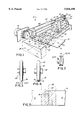
- FIG. 1 is a perspective view of a presently preferred embodiment of a transport mechanism and burster assembly for feeding a stream of tickets and separating the adjacent tickets along a line of weakness within a dispensing unit;
- FIG. 2 is an enlarged plan view of the pulley wheel of the burster assembly of FIG. 1;
- FIG. 3 is a view of the prior art burster wheel
- FIG. 4 is a view of a presently preferred embodiment of the burster wheel according to this invention.
- FIG. 5 is a top plan view of the line of weakness between a pair of adjacent tickets showing an increased range of effectiveness of the burster wheel of the present invention.
- a transport mechanism and burster assembly 10 is shown in FIG. 1 for a lottery ticket dispenser (not shown).
- a typical lottery ticket dispenser is shown in U.S. Pat. No. 4,982,337, the disclosure of which is hereby incorporated by reference.
- a plurality of individual tickets 12 are connected in a fanfold strip or stream 14. Individual tickets 12 are separated from an adjacent ticket by a line of weakness 16 which typically comprises perforations.
- the tickets 12 are provided typically by the state authority in a fanfold stack which is compact and easily transportable and typically include as many as 1,500 tickets in each stack.
- a stack of fanfold tickets 12 are contained in a storage compartment (not shown) in the lottery ticket dispenser.
- Each ticket 12 is connected to an adjacent ticket 12 along the line of weakness 16 and it will be understood that each successive following ticket 12 is separable from an adjacent ticket by a similar line of weakness 16.
- the fanfold stream 14 of tickets 12 is fed along a dispensing path from the storage compartment toward an outlet (not shown).
- the stream 14 is transported along the dispensing path by the transport mechanism 10 including opposed upper feed rollers 18 and lower feed rollers 20 and opposed upper exit rollers 22 and lower exit rollers 24 as shown in FIG. 1.
- a generally circular burster wheel 26 is mounted for rotation between spaced downwardly extending flanges 28 of a burster block 30.
- the burster wheel 26 is mounted for rotation on the burster block 30 on an axle 32 extending through cylindrical hubs 34 on each face of the burster wheel 26 and into the spaced flanges 28.
- the burster block 30 includes a bore hole 36 through which extends a lower burster bar 38.
- the burster block 30 also includes an upper cutout 40 which substantially surrounds an upper burster bar 42.
- the burster block 30 is mounted for a translation along the upper and lower burster bars 38, 42 between opposed side brackets 44, 46 of the transport mechanism 10.
- a cable 48 extends from a first face of the burster block 30 through an aperture 50 in the side bracket 44 and around an upper idler roller 52 and a lower idler roller 54.
- the cable 48 also extends from an opposite face of the burster block 30 through an aperture 56 in the side bracket 46 and is wound around a driven roller 58 driven by a motor 60.
- the cable 48 preferably includes a tensioning spring 62.
- the idler rollers 52, 54 are each mounted on a post 70, 72, respectively, for rotation and include an arcuate cradle 74 in which the cable 48 contacts the roller 52, 54 (FIG. 2).
- the arcuate configuration of the cradle 74 minimizes stress concentration for the roller 52 or 54 and cable 48 interface and the likelihood that the cable 48 will bind or freeze up when passing over the roller 52 or 54.
- the cable 48 passes over both the upper and lower idler rollers 52, 54 and contacts each roller in a 90° arc thereby minimizing the contact friction with each of the rollers 52, 54 and reducing the failure rate of the components.
- the upper exit rollers 22 are journaled on a common upper exit shaft 63 and the lower exit rollers 24 are journaled similarly on a lower exit shaft 64.
- the upper feed rollers 18 are journaled on a common upper feed shaft 66 and the lower feed rollers 20 are journaled on a common lower feed shaft 68.
- the shafts 62, 64, 66, 68 extend between the bracket 44 and a housing 69 containing a motor (not shown) for rotationally driving the shafts 63, 64, 66, 68 to advance the stream 14 of tickets 12.
- the motors and operation of the transport mechanism 10 are controlled by a control circuit (not shown) as is well known in the art.
- the transport mechanism 10 may include an aligning mechanism comprising a code wheel (not shown) or the like as is disclosed in the '337 patent.
- burster block 30 and burster wheel 26 When the burster block 30 and burster wheel 26 are moved from the rest position illustrated in FIG. 1 toward interception with the dispensing path of the stream 14 of tickets 12 through the action of the cable 48 and motor, the burster wheel 26 will come into contact with the stream 14 of tickets 12 at the side thereof initially then across the stream 14 of tickets 12 to burst the adjacent tickets 12 apart along the line of weakness 16.
- the burster block 30 is moved from right to left as shown in FIG. 1 to burst the leading ticket 12, then left to right to burst the next leading ticket 12, and so on.
- the burster block 30 and wheel 26 translate along the bars to intersect the dispensing path of the stream 14 of tickets 12 perpendicularly. As a result, the path of the burster wheel 26 on the tickets 12 is generally parallel to the line of weakness 16 separating the adjacent tickets 12.
- the burster wheel 26 includes a cylindrical contact surface 76 around the perimeter thereof as shown particularly in FIG. 4.
- the overall outer diameter of the burster wheel 26 is 0.912 inches and the diameter of the central hubs 34 are 0.185 inches.
- the cylindrical contact surface 76 in a presently preferred embodiment is 0.187 inches wide and adjacent each edge of the cylindrical contact surface is a 0.062 inch radius 78.
- the burster wheel 26 is fabricated from nylon or black acetal.
- the improved burster wheel 26 of the present invention advantageously provides an increased effective separation range 80 in which the wheel contacts the stream 14 of tickets 12 and provides an effective separation of the tickets 12.
- the burster wheel 26 of this invention provides the larger effective range 80 as shown in FIG. 5 in which the wheel 26 may contact the stream 14 of tickets 12 and still separate the adjacent tickets 12 along the line of weakness 16 as compared to a range of operation 82 provided by a prior art burster wheel 84 (FIG. 3) having a rounded outer edge contact surface 86.
- the effective range of the presently preferred embodiment of the burster wheel is a total of about 1/4 of an inch or 1/8 of an inch on either side of the line of weakness 16 separating the adjacent tickets 12.
Abstract
Description
Claims (20)
Priority Applications (9)
| Application Number | Priority Date | Filing Date | Title |
|---|---|---|---|
| US08/628,994 US5836498A (en) | 1996-04-10 | 1996-04-10 | Lottery ticket dispenser |
| EP97920202A EP0892703B1 (en) | 1996-04-10 | 1997-04-07 | Lottery ticket dispenser |
| AU24454/97A AU2445497A (en) | 1996-04-10 | 1997-04-07 | Improved lottery ticket dispenser |
| CA002250947A CA2250947C (en) | 1996-04-10 | 1997-04-07 | Improved lottery ticket dispenser |
| PCT/US1997/005761 WO1997037820A1 (en) | 1996-04-10 | 1997-04-07 | Improved lottery ticket dispenser |
| DE69732028T DE69732028T2 (en) | 1996-04-10 | 1997-04-07 | LOTTERY OUTPUT DEVICE |
| AT97920202T ATE285317T1 (en) | 1996-04-10 | 1997-04-07 | LOTTERY DISPENSING DEVICE |
| BR9708555-3A BR9708555A (en) | 1996-04-10 | 1997-04-07 | Improved lottery ticketing equipment |
| ARP970101402A AR004628A1 (en) | 1996-04-10 | 1997-04-09 | DETACHMENT MECHANISM; LOTTERY TICKET DISPENSER USING SUCH REMOVAL MECHANISM AND METHOD FOR USING SUCH DISPENSER. |
Applications Claiming Priority (1)
| Application Number | Priority Date | Filing Date | Title |
|---|---|---|---|
| US08/628,994 US5836498A (en) | 1996-04-10 | 1996-04-10 | Lottery ticket dispenser |
Publications (1)
| Publication Number | Publication Date |
|---|---|
| US5836498A true US5836498A (en) | 1998-11-17 |
Family
ID=24521160
Family Applications (1)
| Application Number | Title | Priority Date | Filing Date |
|---|---|---|---|
| US08/628,994 Expired - Fee Related US5836498A (en) | 1996-04-10 | 1996-04-10 | Lottery ticket dispenser |
Country Status (9)
| Country | Link |
|---|---|
| US (1) | US5836498A (en) |
| EP (1) | EP0892703B1 (en) |
| AR (1) | AR004628A1 (en) |
| AT (1) | ATE285317T1 (en) |
| AU (1) | AU2445497A (en) |
| BR (1) | BR9708555A (en) |
| CA (1) | CA2250947C (en) |
| DE (1) | DE69732028T2 (en) |
| WO (1) | WO1997037820A1 (en) |
Cited By (52)
| Publication number | Priority date | Publication date | Assignee | Title |
|---|---|---|---|---|
| EP1122693A2 (en) | 2000-02-02 | 2001-08-08 | Ewald Mothwurf | A ticket dispenser |
| WO2001066452A1 (en) * | 2000-03-08 | 2001-09-13 | Interlott Technologies, Inc. | Lottery ticket dispenser transport mechanism |
| WO2001075806A1 (en) * | 2000-04-05 | 2001-10-11 | Instant Technologies, Incorporated | Lottery ticket dispensing apparatus |
| US20010034263A1 (en) * | 1998-04-14 | 2001-10-25 | Roberts Brian J. | Gaming system and method |
| US20030085249A1 (en) * | 2001-04-06 | 2003-05-08 | Zih Corp., A Delware Corporation | Carrier-less patch protection including cassette and separation device |
| US6609644B1 (en) * | 1997-09-26 | 2003-08-26 | Instant Technologies, Inc. | Method of dispensing perforated tickets |
| US20030233168A1 (en) * | 1998-08-03 | 2003-12-18 | Interlott Technologies, Inc. | Item vending machine and method |
| US6712253B2 (en) | 2001-06-04 | 2004-03-30 | American Games, Inc. | Apparatus and method for dispensing tickets |
| US6726077B2 (en) * | 1998-04-14 | 2004-04-27 | Gtech Corporation | Ticket dispensing modules and method |
| US6752289B1 (en) * | 2000-10-26 | 2004-06-22 | Gamemax Corporation | Lottery ticket machine |
| US20040200874A1 (en) * | 1997-09-26 | 2004-10-14 | Menna Louis P. | Lottery ticket dispensing apparatus |
| US20050059463A1 (en) * | 2003-07-01 | 2005-03-17 | Mark Gilmore | System and method for dispensing tickets |
| US20050061127A1 (en) * | 2003-07-14 | 2005-03-24 | Kasper Kazmier J. | Device for dispensing a paper product |
| US20060035698A1 (en) * | 1998-04-14 | 2006-02-16 | Roberts Brian J | Gaming device and method |
| US20060071046A1 (en) * | 1998-04-14 | 2006-04-06 | Roberts Brian J | Ticket dispensing modules and method |
| US7032793B2 (en) | 1998-04-14 | 2006-04-25 | Gtech Corporation | Ticket dispensing device, installation and displays |
| US20070239545A1 (en) * | 2000-02-02 | 2007-10-11 | Ewald Mothwurf | Apparatus for use at a point of sale for dispensing at least first and second different tickets |
| US20070241160A1 (en) * | 2006-04-12 | 2007-10-18 | Kenney James W | Automated dispenser |
| US20080083632A1 (en) * | 2005-05-19 | 2008-04-10 | Emsize Ab | Board Blank for Producing a Packaging Corner, and Packaging Corner |
| US7364058B2 (en) | 1997-09-26 | 2008-04-29 | Scientific Games International, Inc. | Ticket dispensing apparatus |
| US20090163263A1 (en) * | 2007-12-19 | 2009-06-25 | Scientific Games International, Inc. | Method and System for Multiple In-Lane Lottery Ticket Sales at a Retail Establishment |
| US20100155290A1 (en) * | 2008-08-19 | 2010-06-24 | Hanko Kiessner | Box template with integrated corner protectors |
| WO2010091043A1 (en) * | 2009-02-04 | 2010-08-12 | Packsize, Llc | Infeed system |
| US20110186618A1 (en) * | 2008-08-19 | 2011-08-04 | Hanko Keissner | Box template with integrated corner protectors |
| WO2012003167A1 (en) * | 2010-07-02 | 2012-01-05 | Packsize Llc | Infeed guide system |
| US20140053514A1 (en) * | 2012-08-21 | 2014-02-27 | Larry C. Gess | Method and apparatus for changing a strip of sealed bag precursors in to open bags |
| US8777550B2 (en) | 2008-07-03 | 2014-07-15 | Niklas Pettersson | Zero velocity stacking device |
| US20140336026A1 (en) * | 2012-01-09 | 2014-11-13 | Packsize Llc | Converting machine with an upward outfeed guide |
| US9139317B2 (en) | 2012-08-21 | 2015-09-22 | Intertape Polymer Corp. | Method and apparatus for opening bags while maintaining a continuous strip of bag precursors |
| US9205972B2 (en) | 2012-01-26 | 2015-12-08 | Intralot S.A.—Integrated Lottery Systems and Services | Methods and systems for dispensing |
| US9262870B2 (en) | 2010-10-28 | 2016-02-16 | Intralot S.A.—Integrated Lottery Systems and Services | Methods and a system for dispensing |
| US20160171784A1 (en) * | 2013-08-05 | 2016-06-16 | Beijing Fulei Industrial & Commercial Co., Ltd. | Lottery ticket dispensing device |
| US9580202B2 (en) | 2012-01-06 | 2017-02-28 | Packsize Llc | Foldable box template background |
| US9969142B2 (en) | 2011-11-10 | 2018-05-15 | Packsize Llc | Converting machine |
| US10229466B2 (en) | 2015-07-17 | 2019-03-12 | Scientific Games International, Inc. | Method and system for enhanced lottery ticket accounting and sales at a retail establishment level |
| US10373443B2 (en) | 2016-06-21 | 2019-08-06 | Scientific Games International, Inc. | Method and system for enhanced lottery ticket activation and sale at a retail establishment with subsequent billing and accountability of sold tickets |
| US10672234B2 (en) | 2015-07-17 | 2020-06-02 | Scientific Games International, Inc. | Method and system for enhanced lottery ticket accounting and sales with smart bin dispensers at a retail establishment |
| US10836516B2 (en) | 2014-12-29 | 2020-11-17 | Packsize Llc | Methods of forming packaging templates |
| US10850469B2 (en) | 2016-06-16 | 2020-12-01 | Packsize Llc | Box forming machine |
| US11173685B2 (en) | 2017-12-18 | 2021-11-16 | Packsize Llc | Method for erecting boxes |
| US11214032B2 (en) | 2016-06-16 | 2022-01-04 | Packsize Llc | Box template production system and method |
| US11242214B2 (en) | 2017-01-18 | 2022-02-08 | Packsize Llc | Converting machine with fold sensing mechanism |
| US11247427B2 (en) | 2018-04-05 | 2022-02-15 | Avercon BVBA | Packaging machine infeed, separation, and creasing mechanisms |
| US11286073B2 (en) | 2017-03-06 | 2022-03-29 | Packsize Llc | Box erecting method and system |
| US20220114841A1 (en) * | 2020-10-14 | 2022-04-14 | Scientific Games International, Inc. | Lottery Ticket Dispensing Unit with a Shuttle Separator Device |
| US11305903B2 (en) | 2018-04-05 | 2022-04-19 | Avercon BVBA | Box template folding process and mechanisms |
| US11446891B2 (en) | 2017-06-08 | 2022-09-20 | Packsize Llc | Tool head positioning mechanism for a converting machine, and method for positioning a plurality of tool heads in a converting machine |
| US11524474B2 (en) | 2018-11-30 | 2022-12-13 | Packsize Llc | Adjustable cutting and creasing heads for creating angled cuts and creases |
| US11642864B2 (en) | 2018-09-05 | 2023-05-09 | Packsize Llc | Box erecting method and system |
| US11701854B2 (en) | 2019-03-14 | 2023-07-18 | Packsize Llc | Packaging machine and systems |
| US11752725B2 (en) | 2019-01-07 | 2023-09-12 | Packsize Llc | Box erecting machine |
| US11878825B2 (en) | 2018-06-21 | 2024-01-23 | Packsize Llc | Packaging machine and systems |
Citations (18)
| Publication number | Priority date | Publication date | Assignee | Title |
|---|---|---|---|---|
| US3135446A (en) * | 1963-01-21 | 1964-06-02 | Moore Business Forms Inc | Strip severing machines |
| US3894669A (en) * | 1973-11-19 | 1975-07-15 | Granite State Machine Company | Friction feed ticket dispenser |
| US4094451A (en) * | 1976-11-04 | 1978-06-13 | Granite State Machine Co., Inc. | Lottery ticket dispenser for break-resistant web material |
| US4140259A (en) * | 1977-09-12 | 1979-02-20 | Frank Kostka | Ticket dispenser |
| US4261497A (en) * | 1979-01-18 | 1981-04-14 | Pitney Bowes Inc. | Bursting apparatus |
| US4375189A (en) * | 1981-04-30 | 1983-03-01 | Hobart Corporation | Label printer |
| US4454973A (en) * | 1982-11-26 | 1984-06-19 | Pitney Bowes Inc. | Perforation burst cone device |
| US4529114A (en) * | 1983-09-09 | 1985-07-16 | Moore Business Forms, Inc. | Form burster |
| US4616773A (en) * | 1984-04-27 | 1986-10-14 | Precision Handling Devices Inc. | Forms feeding apparatus |
| US4618085A (en) * | 1983-06-30 | 1986-10-21 | Kabushiki Kaisha Toshiba | Sheet separating apparatus |
| US4623081A (en) * | 1985-06-26 | 1986-11-18 | Ncr Corporation | Burster apparatus for continuous forms |
| US4697726A (en) * | 1985-09-11 | 1987-10-06 | Electronique Serge Dassault | Device for cutting a strip of paper or similar material along preestablished transverse lines of weakness |
| US4940347A (en) * | 1988-02-16 | 1990-07-10 | Lund Company | Paper tractor feed separator |
| US4982337A (en) * | 1987-12-03 | 1991-01-01 | Burr Robert L | System for distributing lottery tickets |
| US5060838A (en) * | 1990-11-29 | 1991-10-29 | Pitney Bowes Inc. | Clam shell housing for dual web bursting apparatus |
| US5133615A (en) * | 1989-09-07 | 1992-07-28 | Tokyo Electric Co., Ltd. | Ticket issuing machine |
| US5141142A (en) * | 1989-08-28 | 1992-08-25 | Pitney Bowes Inc. | Method and apparatus for bursting perforated web material |
| US5215383A (en) * | 1990-12-19 | 1993-06-01 | Cubic Automatic Revenue Collection Group | Ticket stock and ticket dispenser |
Family Cites Families (5)
| Publication number | Priority date | Publication date | Assignee | Title |
|---|---|---|---|---|
| GB703237A (en) * | 1948-06-26 | 1954-02-03 | Egry Ltd | Improvements in and relating to devices for the continuous separation of forms from a web of paper or the like |
| US2846005A (en) * | 1953-12-18 | 1958-08-05 | Wilson Joe Biggs | Trimmer or paper cutter |
| US5001955A (en) * | 1990-04-13 | 1991-03-26 | Sumitsu & Company, Limited | Paper-cutter |
| WO1993014937A1 (en) * | 1992-02-03 | 1993-08-05 | Curtis Manufacturing Company, Inc. | Paper burster and method |
| WO1994011164A1 (en) * | 1992-11-18 | 1994-05-26 | Lottery Enterprises, Incorporated | Perforation detection and ticket dispensing device and method |
-
1996
- 1996-04-10 US US08/628,994 patent/US5836498A/en not_active Expired - Fee Related
-
1997
- 1997-04-07 AU AU24454/97A patent/AU2445497A/en not_active Abandoned
- 1997-04-07 AT AT97920202T patent/ATE285317T1/en not_active IP Right Cessation
- 1997-04-07 EP EP97920202A patent/EP0892703B1/en not_active Expired - Lifetime
- 1997-04-07 DE DE69732028T patent/DE69732028T2/en not_active Expired - Lifetime
- 1997-04-07 BR BR9708555-3A patent/BR9708555A/en not_active IP Right Cessation
- 1997-04-07 CA CA002250947A patent/CA2250947C/en not_active Expired - Fee Related
- 1997-04-07 WO PCT/US1997/005761 patent/WO1997037820A1/en active IP Right Grant
- 1997-04-09 AR ARP970101402A patent/AR004628A1/en unknown
Patent Citations (18)
| Publication number | Priority date | Publication date | Assignee | Title |
|---|---|---|---|---|
| US3135446A (en) * | 1963-01-21 | 1964-06-02 | Moore Business Forms Inc | Strip severing machines |
| US3894669A (en) * | 1973-11-19 | 1975-07-15 | Granite State Machine Company | Friction feed ticket dispenser |
| US4094451A (en) * | 1976-11-04 | 1978-06-13 | Granite State Machine Co., Inc. | Lottery ticket dispenser for break-resistant web material |
| US4140259A (en) * | 1977-09-12 | 1979-02-20 | Frank Kostka | Ticket dispenser |
| US4261497A (en) * | 1979-01-18 | 1981-04-14 | Pitney Bowes Inc. | Bursting apparatus |
| US4375189A (en) * | 1981-04-30 | 1983-03-01 | Hobart Corporation | Label printer |
| US4454973A (en) * | 1982-11-26 | 1984-06-19 | Pitney Bowes Inc. | Perforation burst cone device |
| US4618085A (en) * | 1983-06-30 | 1986-10-21 | Kabushiki Kaisha Toshiba | Sheet separating apparatus |
| US4529114A (en) * | 1983-09-09 | 1985-07-16 | Moore Business Forms, Inc. | Form burster |
| US4616773A (en) * | 1984-04-27 | 1986-10-14 | Precision Handling Devices Inc. | Forms feeding apparatus |
| US4623081A (en) * | 1985-06-26 | 1986-11-18 | Ncr Corporation | Burster apparatus for continuous forms |
| US4697726A (en) * | 1985-09-11 | 1987-10-06 | Electronique Serge Dassault | Device for cutting a strip of paper or similar material along preestablished transverse lines of weakness |
| US4982337A (en) * | 1987-12-03 | 1991-01-01 | Burr Robert L | System for distributing lottery tickets |
| US4940347A (en) * | 1988-02-16 | 1990-07-10 | Lund Company | Paper tractor feed separator |
| US5141142A (en) * | 1989-08-28 | 1992-08-25 | Pitney Bowes Inc. | Method and apparatus for bursting perforated web material |
| US5133615A (en) * | 1989-09-07 | 1992-07-28 | Tokyo Electric Co., Ltd. | Ticket issuing machine |
| US5060838A (en) * | 1990-11-29 | 1991-10-29 | Pitney Bowes Inc. | Clam shell housing for dual web bursting apparatus |
| US5215383A (en) * | 1990-12-19 | 1993-06-01 | Cubic Automatic Revenue Collection Group | Ticket stock and ticket dispenser |
Cited By (93)
| Publication number | Priority date | Publication date | Assignee | Title |
|---|---|---|---|---|
| US6609644B1 (en) * | 1997-09-26 | 2003-08-26 | Instant Technologies, Inc. | Method of dispensing perforated tickets |
| US7364058B2 (en) | 1997-09-26 | 2008-04-29 | Scientific Games International, Inc. | Ticket dispensing apparatus |
| US20040200874A1 (en) * | 1997-09-26 | 2004-10-14 | Menna Louis P. | Lottery ticket dispensing apparatus |
| US6669071B1 (en) | 1997-09-26 | 2003-12-30 | Instant Technologies, Incorporated | Lottery ticket dispensing apparatus |
| US6932258B1 (en) * | 1998-04-14 | 2005-08-23 | Gtech Corporation | Gaming device and method |
| US7850257B2 (en) | 1998-04-14 | 2010-12-14 | Roberts Brian J | Ticket dispensing device, installation and displays |
| US7381132B2 (en) | 1998-04-14 | 2008-06-03 | Gtech Corporation | Gaming system and method |
| US7032793B2 (en) | 1998-04-14 | 2006-04-25 | Gtech Corporation | Ticket dispensing device, installation and displays |
| US20010034263A1 (en) * | 1998-04-14 | 2001-10-25 | Roberts Brian J. | Gaming system and method |
| US20060071046A1 (en) * | 1998-04-14 | 2006-04-06 | Roberts Brian J | Ticket dispensing modules and method |
| US6726077B2 (en) * | 1998-04-14 | 2004-04-27 | Gtech Corporation | Ticket dispensing modules and method |
| US20060035698A1 (en) * | 1998-04-14 | 2006-02-16 | Roberts Brian J | Gaming device and method |
| US7665394B2 (en) * | 1998-04-14 | 2010-02-23 | Gtech Corporation | Ticket dispensing modules and method |
| US7548797B2 (en) | 1998-08-03 | 2009-06-16 | Gtech Corporation | Item vending machine and method |
| US20030233168A1 (en) * | 1998-08-03 | 2003-12-18 | Interlott Technologies, Inc. | Item vending machine and method |
| US20050033642A1 (en) * | 2000-02-02 | 2005-02-10 | Ewald Mothwurf | Method and an apparatus for promoting a product or brand |
| US7016861B2 (en) | 2000-02-02 | 2006-03-21 | Ewald Mothwurf | Dispensing apparatus for dispensing tickets in reponse to an event |
| EP1122693A2 (en) | 2000-02-02 | 2001-08-08 | Ewald Mothwurf | A ticket dispenser |
| EP1122693A3 (en) * | 2000-02-02 | 2003-01-22 | Ewald Mothwurf | A ticket dispenser |
| US20070239545A1 (en) * | 2000-02-02 | 2007-10-11 | Ewald Mothwurf | Apparatus for use at a point of sale for dispensing at least first and second different tickets |
| US20030115102A1 (en) * | 2000-02-02 | 2003-06-19 | Ewald Mothwurf | Method and an apparatus for promoting a product or brand |
| US6578735B1 (en) * | 2000-02-02 | 2003-06-17 | Ewald Mothwurf | Method and an apparatus for promoting a product or brand |
| WO2001066452A1 (en) * | 2000-03-08 | 2001-09-13 | Interlott Technologies, Inc. | Lottery ticket dispenser transport mechanism |
| WO2001075806A1 (en) * | 2000-04-05 | 2001-10-11 | Instant Technologies, Incorporated | Lottery ticket dispensing apparatus |
| US6752289B1 (en) * | 2000-10-26 | 2004-06-22 | Gamemax Corporation | Lottery ticket machine |
| US20030085249A1 (en) * | 2001-04-06 | 2003-05-08 | Zih Corp., A Delware Corporation | Carrier-less patch protection including cassette and separation device |
| US7201343B2 (en) | 2001-04-06 | 2007-04-10 | Zih Corp. | Carrier-less patch protection including cassette and separation device |
| US6712253B2 (en) | 2001-06-04 | 2004-03-30 | American Games, Inc. | Apparatus and method for dispensing tickets |
| US20050059463A1 (en) * | 2003-07-01 | 2005-03-17 | Mark Gilmore | System and method for dispensing tickets |
| US7756742B2 (en) | 2003-07-01 | 2010-07-13 | Scientific Games International, Inc. | System and method for dispensing tickets |
| US20050061127A1 (en) * | 2003-07-14 | 2005-03-24 | Kasper Kazmier J. | Device for dispensing a paper product |
| US7562798B2 (en) | 2004-07-01 | 2009-07-21 | Scientific Games International, Inc. | Ticket dispensing apparatus |
| US20080290127A1 (en) * | 2004-07-01 | 2008-11-27 | Anthony Bartolone | Ticket Dispensing Apparatus |
| US7913896B2 (en) | 2005-05-19 | 2011-03-29 | Emsize Ab | Board blank for producing a packaging corner, and packaging corner |
| US20080083632A1 (en) * | 2005-05-19 | 2008-04-10 | Emsize Ab | Board Blank for Producing a Packaging Corner, and Packaging Corner |
| US20070241160A1 (en) * | 2006-04-12 | 2007-10-18 | Kenney James W | Automated dispenser |
| US7874509B2 (en) * | 2006-04-12 | 2011-01-25 | Kenney James W | Automated dispenser |
| EP1978488A2 (en) | 2007-04-05 | 2008-10-08 | Ewald Mothwurf | Apparatus for use at a point of sale for dispensing at least first and second different tickets |
| US20090163263A1 (en) * | 2007-12-19 | 2009-06-25 | Scientific Games International, Inc. | Method and System for Multiple In-Lane Lottery Ticket Sales at a Retail Establishment |
| US8777550B2 (en) | 2008-07-03 | 2014-07-15 | Niklas Pettersson | Zero velocity stacking device |
| US20100155290A1 (en) * | 2008-08-19 | 2010-06-24 | Hanko Kiessner | Box template with integrated corner protectors |
| US20110186618A1 (en) * | 2008-08-19 | 2011-08-04 | Hanko Keissner | Box template with integrated corner protectors |
| US8584928B2 (en) | 2008-08-19 | 2013-11-19 | Packsize Llc | Box template with integrated corner protectors |
| US8256620B2 (en) | 2008-08-19 | 2012-09-04 | Packsize Llc | Box template with integrated corner protectors |
| EP2393743A4 (en) * | 2009-02-04 | 2013-03-20 | Packsize Llc | Infeed system |
| EP2393743A1 (en) * | 2009-02-04 | 2011-12-14 | Packsize, LLC | Infeed system |
| RU2503608C2 (en) * | 2009-02-04 | 2014-01-10 | ПЭКСАЙЗ ЭлЭлСи | Feed system, processing machine using it and package of fan-fold material |
| WO2010091043A1 (en) * | 2009-02-04 | 2010-08-12 | Packsize, Llc | Infeed system |
| CN102361809B (en) * | 2009-02-04 | 2015-09-09 | 帕克赛兹有限责任公司 | Feeding system |
| US9771231B2 (en) | 2009-02-04 | 2017-09-26 | Packsize Llc | Infeed system |
| US9393753B2 (en) | 2010-07-02 | 2016-07-19 | Packsize Llc | Infeed guide system |
| WO2012003167A1 (en) * | 2010-07-02 | 2012-01-05 | Packsize Llc | Infeed guide system |
| US9262870B2 (en) | 2010-10-28 | 2016-02-16 | Intralot S.A.—Integrated Lottery Systems and Services | Methods and a system for dispensing |
| US9262871B2 (en) | 2010-10-28 | 2016-02-16 | Intralot S.A.—Integrated Lottery Systems and Services | Methods and a system for dispensing |
| US11400680B2 (en) | 2011-11-10 | 2022-08-02 | Packsize Llc | Converting machine |
| US11731385B2 (en) | 2011-11-10 | 2023-08-22 | Packsize Llc | Converting machine |
| US9969142B2 (en) | 2011-11-10 | 2018-05-15 | Packsize Llc | Converting machine |
| US9580202B2 (en) | 2012-01-06 | 2017-02-28 | Packsize Llc | Foldable box template background |
| US9969522B2 (en) | 2012-01-06 | 2018-05-15 | Packsize Llc | Foldable box template |
| US10052838B2 (en) * | 2012-01-09 | 2018-08-21 | Packsize Llc | Converting machine with an upward outfeed guide |
| US20140336026A1 (en) * | 2012-01-09 | 2014-11-13 | Packsize Llc | Converting machine with an upward outfeed guide |
| US9205972B2 (en) | 2012-01-26 | 2015-12-08 | Intralot S.A.—Integrated Lottery Systems and Services | Methods and systems for dispensing |
| US9352525B2 (en) | 2012-08-21 | 2016-05-31 | Intertape Polymer Corp. | Method and apparatus for changing a strip of sealed bag precursors in to open bags |
| US9139317B2 (en) | 2012-08-21 | 2015-09-22 | Intertape Polymer Corp. | Method and apparatus for opening bags while maintaining a continuous strip of bag precursors |
| US8904740B2 (en) * | 2012-08-21 | 2014-12-09 | Intertape Polymer Corp. | Method and apparatus for changing a strip of sealed bag precursors in to open bags |
| US20140053514A1 (en) * | 2012-08-21 | 2014-02-27 | Larry C. Gess | Method and apparatus for changing a strip of sealed bag precursors in to open bags |
| US20160171784A1 (en) * | 2013-08-05 | 2016-06-16 | Beijing Fulei Industrial & Commercial Co., Ltd. | Lottery ticket dispensing device |
| US9741176B2 (en) * | 2013-08-05 | 2017-08-22 | Beijing Fulei Industrial & Commercial Co., Ltd. | Lottery ticket dispensing device |
| US10836516B2 (en) | 2014-12-29 | 2020-11-17 | Packsize Llc | Methods of forming packaging templates |
| US11247789B2 (en) | 2014-12-29 | 2022-02-15 | Packsize Llc | Method of converting sheet material into a custom packaging template |
| US10672234B2 (en) | 2015-07-17 | 2020-06-02 | Scientific Games International, Inc. | Method and system for enhanced lottery ticket accounting and sales with smart bin dispensers at a retail establishment |
| US10229466B2 (en) | 2015-07-17 | 2019-03-12 | Scientific Games International, Inc. | Method and system for enhanced lottery ticket accounting and sales at a retail establishment level |
| US10850469B2 (en) | 2016-06-16 | 2020-12-01 | Packsize Llc | Box forming machine |
| US11752724B2 (en) | 2016-06-16 | 2023-09-12 | Packsize Llc | Box forming machine |
| US11214032B2 (en) | 2016-06-16 | 2022-01-04 | Packsize Llc | Box template production system and method |
| US11158172B2 (en) | 2016-06-21 | 2021-10-26 | Scientific Games International, Inc. | Method and system for enhanced lottery ticket activation and sale at a retail establishment with subsequent billing and accountability of sold tickets |
| US10373443B2 (en) | 2016-06-21 | 2019-08-06 | Scientific Games International, Inc. | Method and system for enhanced lottery ticket activation and sale at a retail establishment with subsequent billing and accountability of sold tickets |
| US11242214B2 (en) | 2017-01-18 | 2022-02-08 | Packsize Llc | Converting machine with fold sensing mechanism |
| US11584608B2 (en) | 2017-01-18 | 2023-02-21 | Packsize Llc | Converting machine with fold sensing mechanism |
| US11738897B2 (en) | 2017-03-06 | 2023-08-29 | Packsize Llc | Box erecting method and system |
| US11286073B2 (en) | 2017-03-06 | 2022-03-29 | Packsize Llc | Box erecting method and system |
| US11446891B2 (en) | 2017-06-08 | 2022-09-20 | Packsize Llc | Tool head positioning mechanism for a converting machine, and method for positioning a plurality of tool heads in a converting machine |
| US11173685B2 (en) | 2017-12-18 | 2021-11-16 | Packsize Llc | Method for erecting boxes |
| US11305903B2 (en) | 2018-04-05 | 2022-04-19 | Avercon BVBA | Box template folding process and mechanisms |
| US11667096B2 (en) | 2018-04-05 | 2023-06-06 | Avercon BVBA | Packaging machine infeed, separation, and creasing mechanisms |
| US11247427B2 (en) | 2018-04-05 | 2022-02-15 | Avercon BVBA | Packaging machine infeed, separation, and creasing mechanisms |
| US11780626B2 (en) | 2018-04-05 | 2023-10-10 | Avercon BVBA | Box template folding process and mechanisms |
| US11878825B2 (en) | 2018-06-21 | 2024-01-23 | Packsize Llc | Packaging machine and systems |
| US11642864B2 (en) | 2018-09-05 | 2023-05-09 | Packsize Llc | Box erecting method and system |
| US11524474B2 (en) | 2018-11-30 | 2022-12-13 | Packsize Llc | Adjustable cutting and creasing heads for creating angled cuts and creases |
| US11752725B2 (en) | 2019-01-07 | 2023-09-12 | Packsize Llc | Box erecting machine |
| US11701854B2 (en) | 2019-03-14 | 2023-07-18 | Packsize Llc | Packaging machine and systems |
| US20220114841A1 (en) * | 2020-10-14 | 2022-04-14 | Scientific Games International, Inc. | Lottery Ticket Dispensing Unit with a Shuttle Separator Device |
Also Published As
| Publication number | Publication date |
|---|---|
| DE69732028D1 (en) | 2005-01-27 |
| AR004628A1 (en) | 1999-03-10 |
| DE69732028T2 (en) | 2005-12-15 |
| BR9708555A (en) | 2000-01-04 |
| ATE285317T1 (en) | 2005-01-15 |
| CA2250947C (en) | 2003-06-24 |
| EP0892703A4 (en) | 2001-12-05 |
| CA2250947A1 (en) | 1997-10-16 |
| EP0892703B1 (en) | 2004-12-22 |
| WO1997037820A1 (en) | 1997-10-16 |
| AU2445497A (en) | 1997-10-29 |
| EP0892703A1 (en) | 1999-01-27 |
Similar Documents
| Publication | Publication Date | Title |
|---|---|---|
| US5836498A (en) | Lottery ticket dispenser | |
| US20020117528A1 (en) | Lottery ticket dispenser transport mechanism | |
| US7562798B2 (en) | Ticket dispensing apparatus | |
| US4094451A (en) | Lottery ticket dispenser for break-resistant web material | |
| EP0416795B1 (en) | Ticket issuing machine | |
| US4982337A (en) | System for distributing lottery tickets | |
| US7275883B2 (en) | Method for stacking tickets in a printer | |
| US20090159610A1 (en) | Lottery ticket dispenser and ticket bin | |
| US3894669A (en) | Friction feed ticket dispenser | |
| CA2724016C (en) | Methods and apparatus for shingle stacking of tickets in a ticket printer | |
| JPH09207905A (en) | Automatic cutting and discharging device of bundling string of bundling device | |
| EP0036266B1 (en) | Banknote dispensing machine with delivery device for the receipt for the banknotes dispensed | |
| JP2001514584A (en) | Printing press for single sheet and web printing | |
| EP0312316A2 (en) | Coin payout apparatus | |
| JP2002193526A (en) | Sheet delivery device | |
| SE457484B (en) | DEVICE FOR EXHAUSTING OF VARIOUS VALUE Vouchers, SPEC TRAVEL TICKETS, FROM A EXHAUST DEVICE | |
| US5386934A (en) | Ticket dispenser retrofit | |
| US6626096B1 (en) | Redemption ticket maker | |
| GB2247223A (en) | Coin wrapping machine | |
| CN210721624U (en) | Lottery ticket bin, lottery ticket issuing device and lottery ticket vending machine | |
| DE3927692C2 (en) | Device for feeding coin wrapping paper in a coin wrapping machine | |
| JP3618366B2 (en) | Media discharge mechanism | |
| JPS642204Y2 (en) | ||
| JPH0822558A (en) | Ticket ejector | |
| JP3721293B2 (en) | Paper sheet dispensing device |
Legal Events
| Date | Code | Title | Description |
|---|---|---|---|
| AS | Assignment |
Owner name: INTERNATIONAL LOTTERY, INC., OHIO Free format text: ASSIGNMENT OF ASSIGNORS INTEREST;ASSIGNOR:TUREK, EDMUND F.;REEL/FRAME:007952/0480 Effective date: 19960409 |
|
| AS | Assignment |
Owner name: INTERLOTT TECHNOLOGIES, INC., OHIO Free format text: CHANGE OF NAME;ASSIGNOR:INTERNATIONAL LOTTERY, INC.;REEL/FRAME:008773/0323 Effective date: 19970530 |
|
| AS | Assignment |
Owner name: FIFTH THIRD BANK, OHIO Free format text: MORTGAGE OF INTELLECTUAL PROPERTY;ASSIGNOR:INTERLOTT TECHNOLOGIES, INC.;REEL/FRAME:011523/0648 Effective date: 20010123 |
|
| FPAY | Fee payment |
Year of fee payment: 4 |
|
| AS | Assignment |
Owner name: GTECH CORPORATION, RHODE ISLAND Free format text: MERGER;ASSIGNOR:INTERLOTT TECHNOLOGIES, INC.;REEL/FRAME:015642/0697 Effective date: 20031201 |
|
| REMI | Maintenance fee reminder mailed | ||
| LAPS | Lapse for failure to pay maintenance fees | ||
| STCH | Information on status: patent discontinuation |
Free format text: PATENT EXPIRED DUE TO NONPAYMENT OF MAINTENANCE FEES UNDER 37 CFR 1.362 |
|
| FP | Lapsed due to failure to pay maintenance fee |
Effective date: 20061117 |