US5839203A - Impulse dryer - Google Patents
Impulse dryer Download PDFInfo
- Publication number
- US5839203A US5839203A US08/794,900 US79490097A US5839203A US 5839203 A US5839203 A US 5839203A US 79490097 A US79490097 A US 79490097A US 5839203 A US5839203 A US 5839203A
- Authority
- US
- United States
- Prior art keywords
- web
- pressure
- gas
- press
- roll
- Prior art date
- Legal status (The legal status is an assumption and is not a legal conclusion. Google has not performed a legal analysis and makes no representation as to the accuracy of the status listed.)
- Expired - Fee Related
Links
Images


Classifications
-
- D—TEXTILES; PAPER
- D21—PAPER-MAKING; PRODUCTION OF CELLULOSE
- D21F—PAPER-MAKING MACHINES; METHODS OF PRODUCING PAPER THEREON
- D21F3/00—Press section of machines for making continuous webs of paper
- D21F3/02—Wet presses
- D21F3/0281—Wet presses in combination with a dryer roll
-
- D—TEXTILES; PAPER
- D21—PAPER-MAKING; PRODUCTION OF CELLULOSE
- D21F—PAPER-MAKING MACHINES; METHODS OF PRODUCING PAPER THEREON
- D21F3/00—Press section of machines for making continuous webs of paper
- D21F3/02—Wet presses
- D21F3/0272—Wet presses in combination with suction or blowing devices
-
- F—MECHANICAL ENGINEERING; LIGHTING; HEATING; WEAPONS; BLASTING
- F26—DRYING
- F26B—DRYING SOLID MATERIALS OR OBJECTS BY REMOVING LIQUID THEREFROM
- F26B13/00—Machines and apparatus for drying fabrics, fibres, yarns, or other materials in long lengths, with progressive movement
- F26B13/10—Arrangements for feeding, heating or supporting materials; Controlling movement, tension or position of materials
-
- F—MECHANICAL ENGINEERING; LIGHTING; HEATING; WEAPONS; BLASTING
- F26—DRYING
- F26B—DRYING SOLID MATERIALS OR OBJECTS BY REMOVING LIQUID THEREFROM
- F26B13/00—Machines and apparatus for drying fabrics, fibres, yarns, or other materials in long lengths, with progressive movement
- F26B13/24—Arrangements of devices using drying processes not involving heating
- F26B13/28—Arrangements of devices using drying processes not involving heating for applying pressure; for brushing; for wiping
Definitions
- the present invention relates generally to a method and apparatus for drying a wet fiber web using a pressing operation in which one surface of the press is heated to a high temperature.
- the apparatus provides the capability to expose the web to ambient pressures above atmospheric and increasing cooling rates when the press load is released.
- the press may be a linear motion press, a roll press, or a shoe press.
- the web may be a single sheet or a continuous web. More particularly, the invention relates to impulse drying of a wet paper web.
- Impulse drying occurs when a wet paper web, carried on a water absorbing felt, passes through the press nip of a pair of rolls, or a roll and shoe, in which a roll is heated to a high temperature.
- Impulse drying may also be accomplished using a linear press with flat platens, in this case one platen is heated and the other may be at ambient temperature. It is projected that wide commercialization of impulse drying would result in a large industry wide energy savings.
- impulse drying In addition to the impact on energy consumption, impulse drying also has an impact on paper sheet structure and properties. Surface fiber conformability and interfiber bonding are enhanced by transient contact with the hot pressing surface. Impulse drying produces a distinctive density profile through the sheet that is characterized by a dense outer layer. This translates into improved physical properties for many grades of paper.
- One persistent problem with the use of impulse drying is that as the press load is released, the pressure exerted on the heated fluid inside the web is reduced and flash evaporation can occur inside the web. The result is that the web delaminates. This is particularly a problem with heavy weight grades of paper. It has been a major constraint in the commercialization of impulse drying.
- Thermal diffusivity is given as K/ ⁇ C V where K is the thermal conductivity, ⁇ is the density and C V is the specific heat. The magnitude of this quantity determines the rate at which a body with a nonuniform temperature approaches equilibrium.
- the units of thermal diffusivity, after cancelling like terms, are meter 2 per second (m 2 /s).
- the press surface must be impermeable to steam since, if a porous material is used to reduce the thermal diffusivity of the press surface, the characteristic density profile of impulse drying is not produced. Orloff shows that a non-permeable, low thermal diffusivity press surface allows higher press surface temperatures to be used for some furnishes, as compared to a high thermal diffusivity surface.
- a typical high thermal diffusivity surface is steel.
- a low thermal diffusivity surface can be produced using ceramics, polymers, inorganic plastics, composite materials and cermets. At the higher press surface temperatures made possible by a low thermal diffusivity surface, the water removal efficiency of impulse drying exceeds that of double felted pressing. However, low thermal diffusivity press surface will produce web delamination if the heated press surface is at too high a temperature.
- the method and apparatus are effective at inhibiting web delamination regardless of press surface thermal diffusivity, web internal structure, web basis weight, or web internal liquid.
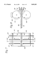
- FIG. 1 is a schematic side view of a roller press that is designed to perform heated press surface pressing at elevated pressures
- FIG. 2 is a plot of load pressure profiles associated with pressing operation
- FIG. 3 is a plot of average outgoing solids as a function of platen set point temperatures, associated with the load pressure profiles of FIG. 2;
- FIG. 4 is a plot of average Coefficient Variation of the specific elastic as a function of set point temperature, corresponding to load pressure profiles of FIG. 2;
- FIG. 5 is a plot of average specific elastic modulus as a function of platen sub-point temperature, corresponding to the load pressure profiles of FIG. 2;
- FIG. 6 is a plot of low pressure as a function of time showing decompression of a treated web according to an alternative arrangement wherein the web exiting the rollers is passed into a region of elevated gas pressure;
- FIG. 7 is a schematic end view of another industrial implementation of the invention.
- FIG. 8 is a schematic side view of the apparatus shown in FIG. 6 taken along line 8--8;
- FIG. 9 is a schematic end view of another industrial implementation of the invention.
- FIG. 10 is a schematic side view of the apparatus shown in FIG. 8 taken along line 10--10;
- FIG. 11 is a schematic side view of a further industrial implementation of the invention.
- FIG. 12 is a schematic end view of the apparatus shown in FIG. 10 taken along line 12--12;
- FIG. 13 is a schematic side view of an electrohydraulic press, pressure cylinder and pressure piston that is designed to perform heated press surface pressing at elevated pressures;
- FIG. 14 is a fragmentary schematic side view of an alternative roller press illustrating features of the present invention.
- FIG. 15 is an enlarged fragmentary view thereof
- FIG. 16 is a fragmentary schematic side view of another alternative roller press illustrating features of the present invention.
- FIG. 17 is an enlarged fragmentary view thereof.
- the present invention is directed generally to a method and apparatus for drying a wet fiber web or sheet using a heated surface press and an important application is impulse drying.
- the present invention can employ a wide range of commercial apparatus, including a linear motion press, a roll nip press, a shoe press, or a wide nip press.
- the present invention provides heated press surface pressing at elevated pressures, which are released with a relatively shallow slope decompression curve.
- the shallow slope decompression can be accomplished using a variety of different techniques. For example, when a roll press is employed, the web exiting the nip formed between the press rolls is wrapped an appropriate amount about the surface of the heated roll to provide a final stage of pressurization for the treated web.
- the web exiting the nip between the rollers can be subjected to a region of elevated gas pressure and/or an increased cooling rate which coincides with the region the sheet or web occupies when the press load on the web or sheet is released.
- the elevated gas pressure need only be a fraction of the pressure corresponding to the thermodynamic saturation pressure of the liquid inside the web when the liquid is at a temperature equal to the heated press surface temperature.
- the pressurizing gas may be air or other suitably inert gas which does not react in an undesirable manner with the web, vapor or apparatus.
- the gas may be cooled or serve to cool below ambient temperatures. The method inhibits web delamination regardless of press surface thermal diffusivity, web internal structure, web basis weight, or web internal liquid.
- One preferred embodiment of the apparatus includes: apparatus for drying a fiber web comprising, in combination, pressing means for said web, including a heated roll and another roll, together forming a nip through which the web passes, the apparatus further comprising web wrapping means for wrapping the web exiting the nip between the rollers, about the heated roll, so as to prolong pressure on the web for a time period at least between one to two times as great as the time period during which the web is pressed in the nip between the rolls.
- Another preferred embodiment includes: apparatus for drying a fiber web comprising, in combination, pressing means for said web, a gas pressure chamber adjacent said pressing means, means for introducing pressurized gas into said pressure chamber, means for controlling gas pressure in said gas pressure chamber so as to prolong pressure on the web for a time period at least between one to two times as great as the time period during which the web is pressed in the nip between the rolls, and means for venting gas from said gas pressure chamber.
- the chamber may enclose the entire press.
- the chamber may enclose either the entire press or only the exit area in the region of the press nip.
- the present invention is directed to the discovery that web delamination can be eliminated, regardless of press surface thermal diffusivity, web specific surface, web basis weight, or web internal liquid, by providing a prolonged, gradually tapering decompression as the press load on the web is released.
- Different press arrangements including rotary and non-rotating presses such as linear motion presses and shoe presses, can be provided for achieving the prolonged, gradually tapering decompression which prevents delamination over a wide range of commercially important platen or roller press temperatures.
- the concluding portion of the decompression cycle may be obtained in a number of different ways.
- the web may be partially wrapped about a heated press roll to prolong the application of pressure to a web exiting the press roll nip.
- the web exiting the press roll nip may be commercially made to enter a pressurized environment.
- the concluding shallow slope decompression step is preferably accomplished without requiring use of pressurized gas at the exit of the press rolls.
- decompression can also be concluded with the use of a pressurized gas which is introduced to a pressure chamber, preferably at a temperature below the ambient temperature.
- a gas at ambient pressure or which is heated to a temperature above the ambient temperature may also be used, however the gas pressure required to inhibit delamination may need to be increased.
- the pressurizing gas may be air or another suitable gas which does not react in an undesirable manner with the web, vapor or apparatus.
- Apparatus in FIG.1 includes a roll press generally indicated at 10.
- the roll press 10 includes a heated roll 12, a heater 14 associated with roll 12 and a lower unheated roll 16.
- a web 18 passing through a nip 20 formed between rolls 12, 16 is comprised of two layers of material, with the upper layer including a fiber web to be dried, overlaid on top of a similarly sized felt web used to transport the fiber web.
- An arm 22 is driven by an operator 24 under control of a computer 26.
- Web 18 is moved in a downstream direction indicated by arrows 30, using conventional drive mechanism (not shown).
- arm 22 is movable in opposite directions and is positioned so as to contact web 18 in a way which alters its path of travel.
- the portion of web 18 shown in FIG. 1 has a generally S-shaped configuration, with arm 22 being raised in contact with web 18 so that the downstream portion (i.e. downstream of nip 20) is at a higher elevation than the upstream portion of the web. This, in effect, causes the downstream portion of web 18 to wrap about a portion of heated roll 12 immediately after exiting nip 20.
- the amount of wrap of the web about the heated roll can be varied.
- the performance of drying of the web was carefully studied, particularly with respect to the effects on the web of impulse drying for varying amounts of wrap about the heated roll 12.
- the heater 14 is operated so as to maintain the temperature of roll 12 at different desired values, representative of conventional industrial operating conditions. Delamination of the web was noted for certain heated roll temperatures and wrap conditions.
- wrap arms have been employed with heated rolls to treat paper webs.
- the effect of the wrap arm control has generally speaking been viewed with regard to overall or long term effects on the paper web observed at a downstream location.
- the emphasis here has been to study the thermodynamic effects and other effects on the web immediately after its exit from the nip formed between the press rolls.
- pressure on web 18 approaches a maximum value at the nip, usually regarded as a line of contact between the press rolls exerted on the web which travels in a direction generally a tangent to the roll surfaces at their line of contact.
- pressure on the web is reduced to a point associated with the ambient environment.
- curve NO indicates pressure experienced by the web without the effect of wrap arm 2, i.e. with the path of web travel being along a generally straight line upstream and downstream of the press rolls and generally tangent to the line contact between the press rolls.
- curve NO has the shortest duration, lasting for approximately 20 milliseconds.
- the remaining curves shown in FIG. 2 are associated with varying amounts of wrap of the web about the heated roll 12 with the amount of wrap increasing from curve C to curve B, and with curve A showing the greatest amount of wrap of the web about the heated roll.
- the tests were concerned with modification of the decompression profile of the web immediately upon exiting the press roll nip.
- the ambient pressure surrounding the impulse dryer was maintained at 1 atmosphere (101 kPa absolute) while the post nip pressure profile was modified by adding a shallow slope ramp profile.
- the ramp profile extension may be achieved in a number of different ways, but is preferably implemented by operation of the post impulse drying roll wrap associated with operation of arm 22.
- curve NO has an initial generally straight line portion (i.e. minimal curvature) between time zero and approximately 5 ms. Curve NO then takes on a continuously curved portion between times 5 ms and 20 ms, with the curve terminating at 20 ms at ambient pressure of 101 kPa. In general, the greatest pressure drop associated with curve NO takes place along the initial straight line portion, where pressure drops from an initial value of 4400 kPa to a value of approximately 800 kPa.
- curve NO is carried out with no wrap of the web about either press roll. Accordingly, applied pressure to the web is free to drop in an unrestrained manner after the web exits the nip between the press rolls.
- curves A, B and C involve the application of pressure to the web after the web exits the nip between the press rolls, thus prolonging application of pressure to the web.
- the four curves of the test begin with approximately the same initial value and the initial straight line or minimal curvature portions are of somewhat comparable lengths. As can be seen in FIG.
- curves A, B and C have initial straight line, minimal curvature extending between initial pressure values of 4400 kPa to a value of approximately 1200 kPa, generally one-fourth the initial, starting value.
- the transition from straight line or minimal curvature operation to a continuously curved transition operation occurs at approximately 7 ms.
- continuous curved operation continues until time approximately 25 ms where operation is concluded with a final straight line or minimal curvature portion having a "shallow" or gradually tapering slope, substantially shallower slope than preceding portions of the decompression operation and extending over a substantial amount of time compared to the duration of the preceding decompression operations.
- curve A is a first operation of approximately 7 ms duration, a transition operation between approximately 7 ms and approximately 27 ms.
- the concluding generally straight-line with minimal curvature portion extends between 27 ms and approximately 135 ms.
- the ending time period is at least between two to eight times longer than the first portion of the operating curve and that the pressure reduced over the first portion of the operating curve is at least between two to eight times greater than the pressure reduced over the final portion of the operating curve.
- curves B and C are of increasingly shorter duration than curve A but also exhibit the same shallow slowly changing operating curve. Even for the shorter operating curves B and C, the time duration of their concluding operating portion, that exhibiting the characteristic shallow slope, is still several times, at least two to eight times, longer than the initial period of operation which herein lasts approximately the first seven milliseconds after web pressure falls below a maximum value.
- the coefficient of variation of the specific elastic modulus was determined using out-of-plane ultrasound techniques of conventional nature.
- a plot of these values with respect to platen set-point temperature is shown in FIG. 4, corresponding to the ramp profiles of FIG. 2.
- Sheets in which delamination has been observed were found to have Coefficients of Variation in excess of between 10 and 15%.
- a delamination limit of approximately 12% is shown in FIG. 4.
- FIG. 4 lower values of Coefficients of Variation are associated with more desirable product characteristics.
- sheets dried using the NO ramp exhibited delamination at all platen set-point temperatures investigated. As can be seen in FIG.
- ramp C was effective in preventing delamination of only a portion of its operating curve, generally corresponding to platen set-point temperatures less than 200° C.
- decompression profiles A and B were effective in preventing delamination at all platen set-point temperatures.
- FIG. 5 shows an increase in specific elastic modulus with increased platen set-point temperature for sheets produced using the conversion operating curves A and B in FIG. 2.
- curves NO and C have generally lower values of average specific elastic modulus and further have an opposite direction of curvature compared to operating curves A and B.
- the present invention is effective in reducing the probability of delamination by modifying the post-nip decompression process. Based upon theoretical considerations using thermodynamic principles, it is believed that the reduced probability of delamination is associated with a reduction in the extent of internal expansion of the web exiting the press roll nip, a lengthening of the time during which flashed a vapor can escape from the web, and a reduction of the forces exerted on the web which lead to delamination.
- the apparatus includes: a chamber for containing the pressurizing gas or the equivalent, means of introducing the pressurizing gas, means of monitoring the pressure of the pressurizing gas, means of controlling the pressure of the pressurized gas, means of venting the pressurizing gas, means of introducing the sheet or web to the press, and means of removing the sheet or web from the pressurized chamber.
- the magnitude of the gas pressure required to prevent delamination is dependent on the liquid internal to the web, the amount of liquid internal to the web, the web internal structure, the web basis weight, and the thermal diffusivity of the heated press surface.
- the elevated gas pressure need only be a fraction of the pressure corresponding to the thermodynamic saturation pressure of the liquid inside the web when the liquid is at a temperature equal to the heated press surface temperature. The purpose is not to inhibit flashing, but rather to control the forces exerted on the web structure by the vapor either resident in the web or generated in the web as the press load is released.
- the chamber for containing the pressurized gas need only maintain the required pressure to inhibit delamination in the immediate vicinity of the web or sheet.
- the region encompassed by the chamber must include that region occupied by the web or sheet when the press load is released. If desired, the chamber may include the entire press.
- the chamber region must be large enough that the web or sheet is maintained in the pressurized region for a sufficient time to inhibit delamination. This time will vary with web structure, web basis weight, web internal fluid and heated press surface temperature. In the case of a typical paper web containing water this time is less than 2 seconds and in many commercially important conditions is less than 200 ms.
- the chamber need not incorporate a sealed physical structure. In a particular application it may be sufficient to create the effect of a chamber by use of gas jets to create a pressurized region of the required size. If the chamber uses a physical structure to contain the gas, the chamber may leak gas, provided the pressure in the region of the web is maintained and the leaking gas does not damage the apparatus, web or constitute a safety hazard. The leaking of the gas may cause a cooling effect.
- the apparatus must have means of introducing the pressurizing gas to the pressure chamber.
- the method used for introducing the gas should not result in a jet is of gas impacting on the web or sheet surface with sufficient force to cause damage. If the pressure required to inhibit delamination of the web is high enough that such a jet is produced, then the jet must either be oriented so it does not damage the web or sheet or a baffle mechanism must be introduced between the web and the gas jet.
- the method used for introducing the gas to the chamber should incorporate means of adjusting the flow of gas into the chamber.
- the apparatus should include means of monitoring the pressure of the pressurizing gas inside the chamber.
- the method used is dependent on the application. In a batch type process, a simple industrial type gauge may be sufficient. In a continuous process, a pressure transducer providing a continuous output to a control system may be required. The means employed must only provide an indication of the pressure in the chamber sufficient for controlling that pressure. The accuracy and speed of the measurement is that required to inhibit delamination and for efficient operation of the apparatus. Efficient operation is dependent on the application.
- the apparatus comprises a means of venting the pressurized gas.
- the method used should not cause damage to the web.
- the method used for venting the gas should incorporate means of controlling the rate at which the gas is vented.
- the apparatus has means of introducing the sheet or web to the press.
- the method employed need only ensure that the pressure within the chamber is maintained when the press load is released.
- a felt may be used to introduce the web to the press.
- the web or sheet may be introduced manually or by using a mechanical device.
- the apparatus further comprises means of removing the sheet or web from the press and pressure chamber.
- the method used need only ensure that the web or sheet remains pressurized to some extent, over a prolonged period as pressure levels are reduced, so as to inhibit delamination.
- the chamber pressure is maintained. Effective cooling by the gas is desired.
- a felt can be used to transport the web or sheet from the press nip through the pressure chamber.
- the felt also acts as a water receiver.
- the chamber may have a slot opening through which passes the felt and the web. The opening is sealed in such a way that the web is able to pass through and that any gas leakage is limited to that which can be compensated for by the method employed for introducing gas to the chamber.
- the seal may incorporate a flexible wiper or pair of rolls which are in contact with the web or sheet.
- the web or sheet can be removed manually or by using a mechanical device.
- the web or sheet is introduced into a heated surface press having opposed surfaces.
- the heated surface is of a rigid material which can be easily heated, such as steel or steel coated with a material having specific thermal or material properties, i.e., ceramics, polymers, inorganic plastics, composite materials and cermets or any other material with the required strength properties.
- the heated surface may have high or low diffusivity.
- the other surface may either be a rigid material with the strength properties required for the particular press load and application, such as steel, or it may be steel coated with a polymer, or the belt of a shoe press.
- a web of a resilient material such as a felt, is interposed between the unheated surface and the heated surface as the web is introduced to the press.
- the two press surfaces are urged together to provide a compressive force on the web.
- the preferred compressive nip pressure is from about 0.3 MPa to about 10.0 MPa.
- the heated surface is heated to provide a surface temperature between the atmospheric boiling temperature of the internal web fluid and the thermodynamic critical point temperature of the internal web fluid.
- the temperature is from about 100° C. to about 374° C., preferably from about 200° C. to about 300° C.
- the residence time in the press and the pressurized region beyond is adjusted to provide maximum fluid removal.
- the residence times can be from about 10 ms to 1000 ms, preferably from about 20 ms to about 60 ms.
- the residence time is controlled by the speed of the web and the length of the press nip.
- the method of the present invention is useful for drying paper webs having an initial moisture level of from about 75% to about 50%.
- the moisture content of the paper web after being subjected to impulse drying in accordance with the invention will be in the range of from about 65% to about 30%. All percentages used herein are by weight, unless otherwise specified.
- the gas pressure required to inhibit delamination depends on the paper furnish, basis weight and press heated surface temperature. In general, the minimum gage pressure required is about 0.00 MPa (0.00 psig) and the maximum gage pressure required is about 0.70 MPa (100 psig) with a heated press surface temperature of 250° C. These pressures may be reduced by employing a cooled gas to pressurize the chamber into which the web is received after the press load is released.
- the cooled gas will further reduce the mass of liquid which flashes to vapor, increase cooling of the web or sheet, reduce exhaust velocity of vapor, reduce vapor induced drag forces, prevent sonic vapor velocity across constrictions in internal web pores and reduce static force imbalances.
- the gas may be used to cool through its flow or expansion.
- FIG. 6 shows a typical operating curve indicating decompression of a typical web using hybrid techniques for applying pressure to the web to effect impulse drying under commercial important operating conditions, yet without delamination. It will be seen that the curve of FIG. 6 is similar to the operating curves shown in FIG. 2. As with the decompression curves previously examined, the operating curve shown in FIG. 6 is comprised of three portions, an initial portion 50 which is generally straight-line or minimal curvature in nature, a continuously curved intermediate portion 52 and a concluding portion 54 also of minimal curvature, herein referred to as a generally straight-line portion. The first portion of the decompression curve of FIG.
- Curved portion 54 is preferably achieved by applying a gaseous pressure to the web immediately after the web exits the nip between the press rolls, i.e. in a manner such that the operating curve indicated in FIG. 6 is substantially continuous. It will be noted that the rise of gas pressure experienced by the web need not be instantaneous and a typical relatively brief rise time is indicated in FIG. 6 by the short time interval occurring immediately before time T 3 . In the preferred embodiments to follow, it is generally preferred that the curve of FIG. 6 be used to approximate operating curves illustrated above in FIG.
- the ending time period i.e. between times T 3 and T 4
- the initial pressure P 1 be at least two to eight times greater than P 2 , the pressure value at the end of the initial portion of the operating curve, where the greatest amount of pressure reduction takes place.
- the pressure reduced over the first time period (curve portion 50) be at least two to eight times greater than the pressure reduced over the final time period (i.e. with reference to curve portion 54).
- the initial and final operating curve portions i.e. curved portions 50 and 54
- the initial and final operating curve portions have significantly less curvature than the transition portion 52 and accordingly curved portions 50 and 54 are referred to as being generally linear.
- roller press apparatus is generally indicated at 520.
- the roller press 520 is generally identical to the roller press arrangement 10 illustrated in FIG. 1, but with the addition of a high pressure shoe arrangement generally indicated at 522. Included in the shoe arrangement 522 is an air cylinder 524 which urges a shoe 526 toward and away from roller 12.
- a belt 530 supported by rollers 532 travels in a closed path about shoe 526. As illustrated in FIG. 15, a portion of the belt 530 is located between shoe 526 and the web.
- shoe 526 presses the belt 530 against the web, thereby pressing the web against the outer surface of roller 12, so as to augment the effect of lever arm 22 on the web.
- the operating cylinder 524 be controlled by computer 26 so that the overall pressure experienced by the web after it exits the roller nip can be better controlled, and so that the relative balance between the lever arm 22 and the shoe assembly 522 can be maintained at a desired ratio. Further, if desired, the lever arm could be retracted with the shoe assembly 522 alone providing the post-nip pressure on the web. Further, any of the pressurized gas arrangements, such as a gas manifold 506 in FIG. 16, can be employed in conjunction with the shoe arrangement 522, although this has not been found to be necessary.
- Roll press 500 is illustrated, having two different modes or types of post-nip decompression arrangements.
- Roll press 500 is substantially identical to the roll press 10 described above, but with the addition of a high pressure air manifold assembly generally indicated at 502 in which a plurality of air lines 504 are employed to discharge high pressure gas through nozzle arrangement 506 against the web.
- the present invention has found immediate application in drying fibrous webs of paper composition, backed by a supporting felt web.
- air is used as the pressurized gas, but other gas compositions could also be employed.
- the pressurized gas be directed to the side of the web at which the supporting felt is located.
- the lever arm 22 imparts a tension to that side of the web containing the supporting felt. It is preferred that the pressure released through the nozzle arrangement 506 is placed under control of computer 26 so that the cumulative effects on the web can be controlled, along with the proportional balancing of the effects of the lever arm 22 and the air manifold 506.
- the method of the present invention can be implemented on an industrial scale as shown in FIGS. 7 and 8.
- the apparatus in FIGS. 7 and 7 is a roll press. It includes a heated roll 101, a heater 102, a lower unheated roll 103, the web 104 being pressed between the rolls on a felt 105 used for transporting the web 104, a pair of side covers 106 and a number of air knives 107.
- the heated roll 101 and the lower roll 103 are mounted as in a standard roll press and are used to provide the compressive force on the web 104 and felt 105.
- the lower roll 103 can be replaced by a shoe press.
- the air knives 107 are used to direct a flow or gas at the line where the web 104 and heated roll 101 contact cease and at the line where the felt 105 and the roll 103 contact cease.
- the gas flow through the air knives 107 is of sufficient flow rate and of the appropriate direction to produce a high pressure region at the roll nip opening which provides an equivalent pressure chamber.
- the air knives 107 are of sufficient number to produce a uniform high pressure region across the entire face of the heated roll 101 and the lower roll 103.
- the gas used in the air knives 107 can be air or any other gas which does not react with the web 104, felt 105 or apparatus, or create a hazard for the personnel operating the apparatus.
- a gas cooled below ambient temperatures may be used. Use of a cooled gas may reduce the pressure required to inhibit delamination of the web 104.
- the flow of gas may be out of the region the nip can effectively cool.
- the side covers 106 serve to limit the flow of gas across the face of the rolls, web 104 and felt 105 but can be adjusted to allow sufficient flow to cool.
- the air knives 106 directing the gas flow towards the felt 105 can be replaced by a rigid platform which would be positioned directly underneath the felt 105 and would support both the felt 105 and the web 104.
- a pressure probe can be inserted into the region immediately adjacent to the nip opening for the purpose of measuring the pressure generated by the gas flow from the air knives 107.
- the rotation direction of the heated roll 101 and the lower roll 103 are indicated by arrows in FIG. 7.
- the roll rotation serves to propel the felt 105 and the web 104 between the two rolls.
- the heated roll can be constructed of steel, steel coated with a low thermal diffusivity material such as ceramic, or from any other material with the required strength properties.
- the thermal characteristics of the heated roll may affect the gas pressure required to inhibit delamination.
- the method of the present invention can be implemented on an industrial scale as shown in FIGS. 9 and 10.
- the apparatus in FIGS. 9 and 10 is a roll press. It includes a heated roll 201, a heater 202, a lower unheated roll 203, the web 204 being pressed, a felt 205 for transporting the web 204, a pair of side covers 206 and a number of gas inlets 207, a number of gas exhausts 208, a chamber cover 210, flexible seals 209 and rollers 211.
- the flexible seals provide a gas seal between the chamber cover 210 and the heated roll 201 and between the chamber cover 210 and the lower roll 203.
- the rollers 211 provide a gas seal between the chamber cover 210 and the web 204 and between the chamber cover 210 and the felt 205.
- the heated roll 201 and the lower roll 203 are mounted as in a standard roll press and are used to provide the compressive force on the web 204 and felt 205.
- the lower roll 203 can be replaced by a shoe press.
- the gas inlets 207 are used to introduce gas into the chamber formed by the chamber cover 210, the heated roll 201, the lower roll 203 and the side covers 206. Introducing gas into the chamber causes the chamber to pressurize and thus inhibit delamination of the web.
- the gas exhausts 208 can be used to depressurize the chamber and to control the pressure level inside the chamber as well as gas flow through the chamber.
- the gas inlets 207 can also be used to control the chamber pressure.
- the gas flow introduced through the gas inlets 207 needs to be of a direction and volume flow rate that does not damage the web 204 yet produces the desired pressure within the chamber. If the required volume flow rate is high enough that the web 204 may be damaged then a baffle (not shown) should be introduced between the gas inlet 207 and the web 204.
- the gas used to pressurize the chamber can be air or any other gas which does not react with the web 204, felt 205 or apparatus or create a hazard for the personnel operating the apparatus.
- a gas cooled below ambient temperatures may be used. Use of a cooled gas may reduce the pressure required to inhibit delamination of the web 204.
- the chamber portion beneath the felt 205 can be replaced by a rigid platform (not shown) which would be positioned directly beneath the felt 205, and would support both the felt 205 and the web 204.
- a second chamber cover 210 can be added downstream from the first chamber cover 210.
- the region covered by the first chamber cover 210 would be at a pressure P1 and the region between the second chamber cover 210 and the first chamber cover 210 would be at pressure P2, where P1>P2.
- a pressure probe is inserted into each chamber for the purpose of measuring the pressure within the chamber.
- the rotation direction of the heated roll 201 and the lower roll 203 are indicated by arrows in FIG. 10.
- the roll rotation serves to propel the felt 205 and the web 204 between the two rolls.
- the heated roll may be constructed of steel, steel coated with a low thermal diffusivity material such as ceramic, or from any other material with the required strength properties.
- the thermal characteristics of the heated roll may affect the gas pressure required to inhibit delamination.
- the method of the present invention can be implemented on an industrial scale as shown in FIGS. 11 and 12.
- the apparatus in FIGS. 11 and 12 is a roll press. It includes a heated roll 301, a heater 302, a lower unheated roll 303, the web 304 being pressed, a felt 305 for transporting the web 304, a pair of side covers 306, a number of gas inlets 307, a number of gas exhausts 308 and a foil assembly 309.
- the heated roll 301 and the lower roll 303 are mounted as in a standard roll press and are used to provide the compressive force on the web 304 and felt 305.
- the lower roll 303 can be replaced by a shoe press.
- the foil assembly 309 consists of multiple foils 310 which create small closed chambers between successive foils 310 and the web 304 or the felt 305. The sides of the foil assembly 309 are sealed by side covers 306.
- the chamber formed by the foils 310 which is closest to the heated roll 301 and the chamber formed by the foils 310 which is closest to the lower roll 303 are at the highest pressure. Moving downstream from the rolls, the pressure in each succeeding chamber is less than that in the preceding chamber. In this way, the web 304 is subjected to a series of pressure steps which decrease the pressure as the web moves away from the rolls.
- the gas inlets 307 are used to introduce gas into each chamber formed by the foils 310 and the web 304 or felt 305. Introducing gas into the chambers causes the chamber to pressurize and thus inhibit delamination of the web.
- the gas exhaust 308 can be used to depressurize the chamber and to control the pressure level inside the chamber. The gas will tend to flow from the high pressure chambers to the low pressure chambers and out of the gas exhaust 308.
- the gas inlets 307 can also be used to control the chamber pressure.
- the gas flow introduced through the gas inlets 307 needs to be of a direction and volume flow rate that does not damage the web 304 yet produces the desired pressure within the chamber. If the required volume flow rate is high enough that the web 304 may be damaged then a baffle should be introduced between the gas inlet 307 and the web 304.
- the gas used to pressurize the chamber can be air or any other gas which does not react with the web 304 or felt 305, or apparatus or create a hazard for the personnel operating the apparatus.
- a gas cooled below ambient temperatures may be used. Use of a cooled gas may reduce the pressure required to inhibit delamination of the web 304.
- the chamber portion beneath the felt 305 can be replaced by a rigid platform (not shown) which would be positioned directly beneath the felt 305, and would support both the felt 305 and the web 304.
- a pressure probe (not shown) should be inserted into each of the chambers formed by the foils 310.
- the rotation direction of the heated roll 301 and the lower roll 303 are indicated by arrows in FIG. 12.
- the roll rotation services to propel the felt 305 and the web 304 between the two rolls.
- the heated roll may be constructed of steel, steel coated with a low thermal diffusivity material such as ceramic, or from any other material with the required strength properties. The thermal characteristics of the heated roll will affect the gas pressure required to inhibit delamination.
- the apparatus includes a frame 411 on which is mounted a hydraulic cylinder 412.
- the piston of the hydraulic cylinder 413 actuates a pressure cylinder 414 and heated head 415 through a load cell 416.
- a heated platen 422 is mounted at the lower extremity of the heating head 415.
- a thermocouple 423 is mounted between the heating head and the heated platen to measure the temperature of the platen.
- a pressure piston 417 supports a platen 418 on which rests a felt 419.
- the pressure piston also supports a ring 420 on which rests a sheet 421 which is to be pressed.
- a gas inlet 424 is mounted on the upper portion of the pressure cylinder 414.
- a gas exhaust 425 is mounted on the lower portion of the pressure cylinder.
- a pressure transducer 426 is located on the lower portion of the pressure cylinder.
- the pressure piston 417 has a gasket groove 427 and a gasket 428 which provides a dynamic seal when the pressure cylinder 423 and heated platen 422 are moved toward the lower platen 418 to initiate the pressing of the sheet 421.
- the pressure cylinder 414 and pressure piston 417 have dimensions which insure that a dynamic seal is created before the heated platen 422 contacts the raised ring 420 and sheet 421 assembly.
- the movement of the pressure cylinder 414, the introduction of gas through the gas inlet 424 and the exhaust of gas through the gas exhaust 425 are controlled by a computer. Gas introduced through the gas inlet 424 is supplied from a tank (not shown). The gas pressure in the tank is equal to the gas pressure required to inhibit delamination of the sheet being pressed.
- a felt 419 is placed on the lower platen 418 and a paper sheet 421 is placed on the raised ring 420.
- the gas inlet 424 is closed to inhibit gas from flowing into the pressure cylinder 414 and the gas exhaust 425 is open allowing the interior of the pressure cylinder 414 to vent to the atmosphere.
- the downward motion of the pressure cylinder 414 is caused by the hydraulic cylinder 412.
- the gasket 428 Prior to the heated platen 422 contacting the raised ring 420 and sheet 421, the gasket 428 creates a dynamic seal between the pressure cylinder 414 and the pressure piston 417, forming a completely closed chamber and allowing the chamber to be pressurized.
- the pins on the ring 420 contacting the heating head 415 and the ring 420 is pushed downward until the sheet 421 is in contact with the felt 419.
- the heated platen 422 contacts the sheet 421 and both the sheet 421 and the felt 419 are pressed between the heated upper platen 422 and the lower platen 418. While the pressing is in progress the gas exhaust 425 is closed and the gas inlet 424 is opened, pressurizing the chamber.
- the pressure cylinder 414 is moved upward to an intermediate position. In this position, there is sufficient space for the ring 420 and sheet 421 to return to the original position, separating the sheet 421 from the felt 419.
- the intermediate position is such that the gasket 428 still forms a seal between the pressure cylinder 414 and the pressure piston 417 and the integrity of the chamber formed by the pressure cylinder 414 and the pressure piston 417 is not affected.
- This position is maintained for a short period of time, normally less than 2 seconds and preferably less than 10 ms.
- the gas exhaust 425 is opened and the gas inlet 424 is closed, venting the chamber to atmosphere. In the process of venting, the expelling gas cools the sheet by forced convection.
- the pressure cylinder 414 is then raised to the original position allowing the sheet 421 and the felt 419 to be removed.
- Paper hand sheets having 65% moisture, specific surface of 25 m 2 /g, Canadian Standard Freeness (CSF) of 400 ml, and a basis weight of 204 g/m 2 (42 lb/1000 ft 2 ) were prepared and a series of pressing tests were conducted where the device in FIG. 13 was used to impulse dry the sheets at platen temperatures of 120° C., 130° C., 140° C., 150° C., 175° C., 200° C., 260° C. and 330° C.
- the pressing residence time was 60 ms and the maximum platen pressure was about 4.24 MPa.
Abstract
Description
Claims (6)
Priority Applications (1)
| Application Number | Priority Date | Filing Date | Title |
|---|---|---|---|
| US08/794,900 US5839203A (en) | 1995-05-12 | 1997-02-05 | Impulse dryer |
Applications Claiming Priority (3)
| Application Number | Priority Date | Filing Date | Title |
|---|---|---|---|
| US08/440,539 US5598642A (en) | 1995-05-12 | 1995-05-12 | Method and apparatus for drying a fiber web at elevated ambient pressures |
| US08/618,294 US5669159A (en) | 1995-05-12 | 1996-03-18 | Method and apparatus for drying a fiber web at elevated ambient pressures |
| US08/794,900 US5839203A (en) | 1995-05-12 | 1997-02-05 | Impulse dryer |
Related Parent Applications (1)
| Application Number | Title | Priority Date | Filing Date |
|---|---|---|---|
| US08/618,294 Division US5669159A (en) | 1995-05-12 | 1996-03-18 | Method and apparatus for drying a fiber web at elevated ambient pressures |
Publications (1)
| Publication Number | Publication Date |
|---|---|
| US5839203A true US5839203A (en) | 1998-11-24 |
Family
ID=24477124
Family Applications (2)
| Application Number | Title | Priority Date | Filing Date |
|---|---|---|---|
| US08/618,294 Expired - Fee Related US5669159A (en) | 1995-05-12 | 1996-03-18 | Method and apparatus for drying a fiber web at elevated ambient pressures |
| US08/794,900 Expired - Fee Related US5839203A (en) | 1995-05-12 | 1997-02-05 | Impulse dryer |
Family Applications Before (1)
| Application Number | Title | Priority Date | Filing Date |
|---|---|---|---|
| US08/618,294 Expired - Fee Related US5669159A (en) | 1995-05-12 | 1996-03-18 | Method and apparatus for drying a fiber web at elevated ambient pressures |
Country Status (8)
| Country | Link |
|---|---|
| US (2) | US5669159A (en) |
| EP (1) | EP0796945A3 (en) |
| JP (1) | JPH101892A (en) |
| KR (1) | KR970066480A (en) |
| CN (1) | CN1084414C (en) |
| AU (1) | AU721682B2 (en) |
| ID (1) | ID16601A (en) |
| TW (1) | TW358154B (en) |
Cited By (2)
| Publication number | Priority date | Publication date | Assignee | Title |
|---|---|---|---|---|
| US6683284B2 (en) | 2002-03-22 | 2004-01-27 | Metso Paper Karlstad Ab | Thermal roll for papermaking with a fluid circulation system and method therefor |
| US6860968B1 (en) | 2000-05-24 | 2005-03-01 | Kimberly-Clark Worldwide, Inc. | Tissue impulse drying |
Families Citing this family (10)
| Publication number | Priority date | Publication date | Assignee | Title |
|---|---|---|---|---|
| AU2014699A (en) * | 1997-12-21 | 1999-07-12 | International Paper Company | Dimensionally stable paper and paperboard products |
| US6076279A (en) * | 1998-01-09 | 2000-06-20 | Finbark Oy | Method and a device for improving liquid removal |
| SE512944C2 (en) | 1998-10-01 | 2000-06-12 | Sca Research Ab | Method of making paper with a three-dimensional pattern |
| JP4521948B2 (en) * | 2000-08-08 | 2010-08-11 | 四国化工機株式会社 | Sterilizer removal device |
| WO2002025013A1 (en) | 2000-09-20 | 2002-03-28 | Akzo Nobel N.V. | A process for the production of paper |
| US6701637B2 (en) | 2001-04-20 | 2004-03-09 | Kimberly-Clark Worldwide, Inc. | Systems for tissue dried with metal bands |
| JP3602506B2 (en) * | 2002-02-01 | 2004-12-15 | 株式会社協真エンジニアリング | Pressure heating drying method and pressure heating drying apparatus |
| US10201840B2 (en) * | 2012-04-11 | 2019-02-12 | Gpcp Ip Holdings Llc | Process for cleaning a transport belt for manufacturing a paper web |
| DE102012217858A1 (en) * | 2012-09-28 | 2014-06-12 | Papierfabrik August Koehler KG | Drying section and method for drying a web of fibrous material and machine having such a dryer section |
| CN113154862B (en) * | 2021-02-26 | 2022-07-15 | 东莞汇和电子有限公司 | Electronic circuit board assembly piston drying air knife |
Citations (10)
| Publication number | Priority date | Publication date | Assignee | Title |
|---|---|---|---|---|
| US2784652A (en) * | 1954-07-06 | 1957-03-12 | Beloit Iron Works | Paper machine dryer assembly |
| US3799052A (en) * | 1972-02-05 | 1974-03-26 | Kuesters E | Apparatus for the continuous pressure treatment of a web |
| US3938261A (en) * | 1972-12-06 | 1976-02-17 | Anderson James K | Apparatus for improving printing surface of printing material |
| US5071513A (en) * | 1986-12-24 | 1991-12-10 | Sulzer-Escher Wyss Gmbh | Method for the mechanical-thermal dewatering of a fiber stock web |
| US5101574A (en) * | 1989-10-15 | 1992-04-07 | Institute Of Paper, Science & Technology, Inc. | Method and apparatus for drying web |
| US5291666A (en) * | 1993-04-23 | 1994-03-08 | International Paper Company | Apparatus for drying roll material |
| US5327661A (en) * | 1991-01-18 | 1994-07-12 | Institute Of Paper Science And Technology, Inc. | Method and apparatus for drying web |
| US5404654A (en) * | 1993-04-27 | 1995-04-11 | International Paper Company | Chambered nip drying of paperboard webs |
| US5439559A (en) * | 1994-02-14 | 1995-08-08 | Beloit Technologies | Heavy-weight high-temperature pressing apparatus |
| US5649371A (en) * | 1995-02-04 | 1997-07-22 | Voith Sulzer Papiermaschinen Gmbh | Dry unit of a dry end of a machine for producing material webs |
Family Cites Families (9)
| Publication number | Priority date | Publication date | Assignee | Title |
|---|---|---|---|---|
| FI53148B (en) * | 1976-07-05 | 1977-10-31 | Valmet Oy | |
| FI61537C (en) * | 1981-02-19 | 1982-08-10 | Tampella Oy Ab | REFERENCE TO A CONTAINER WITHOUT CONTAINER TORKNING AV EN PAPPERS- ELLER LIKNANDE POROES BANA |
| EP0289477A3 (en) * | 1987-04-28 | 1989-03-08 | Valmet Paper Machinery Inc. | Method for hot-pressing of a paper web and a drying device for the implementation of the method |
| US4788779A (en) * | 1987-06-15 | 1988-12-06 | Pulp And Paper Research Institute Of Canada | Method and apparatus for the rapid consolidation and/or drying of moist porous webs |
| JP2781287B2 (en) * | 1991-03-20 | 1998-07-30 | トーカロ株式会社 | Drying roll |
| JPH0748796A (en) * | 1993-08-06 | 1995-02-21 | Mitsubishi Heavy Ind Ltd | Dryer hood unit of papermaking machine |
| FI97485C (en) * | 1995-02-14 | 1996-12-27 | Valmet Corp | Drying device for drying a fiber web and drying part in a paper machine |
| US5598642A (en) * | 1995-05-12 | 1997-02-04 | Institute Of Paper Science And Technology, Inc. | Method and apparatus for drying a fiber web at elevated ambient pressures |
| US6314659B1 (en) * | 1999-12-14 | 2001-11-13 | Valmet Inc. | Device and method for protecting a carrying fabric |
-
1996
- 1996-03-18 US US08/618,294 patent/US5669159A/en not_active Expired - Fee Related
-
1997
- 1997-02-05 US US08/794,900 patent/US5839203A/en not_active Expired - Fee Related
- 1997-02-27 TW TW086102385A patent/TW358154B/en not_active IP Right Cessation
- 1997-03-15 KR KR1019970008826A patent/KR970066480A/en not_active Application Discontinuation
- 1997-03-17 ID IDP970856A patent/ID16601A/en unknown
- 1997-03-17 AU AU16352/97A patent/AU721682B2/en not_active Ceased
- 1997-03-18 EP EP97104604A patent/EP0796945A3/en not_active Ceased
- 1997-03-18 CN CN97104519A patent/CN1084414C/en not_active Expired - Fee Related
- 1997-03-18 JP JP9064987A patent/JPH101892A/en active Pending
Patent Citations (10)
| Publication number | Priority date | Publication date | Assignee | Title |
|---|---|---|---|---|
| US2784652A (en) * | 1954-07-06 | 1957-03-12 | Beloit Iron Works | Paper machine dryer assembly |
| US3799052A (en) * | 1972-02-05 | 1974-03-26 | Kuesters E | Apparatus for the continuous pressure treatment of a web |
| US3938261A (en) * | 1972-12-06 | 1976-02-17 | Anderson James K | Apparatus for improving printing surface of printing material |
| US5071513A (en) * | 1986-12-24 | 1991-12-10 | Sulzer-Escher Wyss Gmbh | Method for the mechanical-thermal dewatering of a fiber stock web |
| US5101574A (en) * | 1989-10-15 | 1992-04-07 | Institute Of Paper, Science & Technology, Inc. | Method and apparatus for drying web |
| US5327661A (en) * | 1991-01-18 | 1994-07-12 | Institute Of Paper Science And Technology, Inc. | Method and apparatus for drying web |
| US5291666A (en) * | 1993-04-23 | 1994-03-08 | International Paper Company | Apparatus for drying roll material |
| US5404654A (en) * | 1993-04-27 | 1995-04-11 | International Paper Company | Chambered nip drying of paperboard webs |
| US5439559A (en) * | 1994-02-14 | 1995-08-08 | Beloit Technologies | Heavy-weight high-temperature pressing apparatus |
| US5649371A (en) * | 1995-02-04 | 1997-07-22 | Voith Sulzer Papiermaschinen Gmbh | Dry unit of a dry end of a machine for producing material webs |
Cited By (2)
| Publication number | Priority date | Publication date | Assignee | Title |
|---|---|---|---|---|
| US6860968B1 (en) | 2000-05-24 | 2005-03-01 | Kimberly-Clark Worldwide, Inc. | Tissue impulse drying |
| US6683284B2 (en) | 2002-03-22 | 2004-01-27 | Metso Paper Karlstad Ab | Thermal roll for papermaking with a fluid circulation system and method therefor |
Also Published As
| Publication number | Publication date |
|---|---|
| TW358154B (en) | 1999-05-11 |
| AU721682B2 (en) | 2000-07-13 |
| KR970066480A (en) | 1997-10-13 |
| EP0796945A3 (en) | 1997-10-01 |
| EP0796945A2 (en) | 1997-09-24 |
| US5669159A (en) | 1997-09-23 |
| AU1635297A (en) | 1997-09-25 |
| JPH101892A (en) | 1998-01-06 |
| CN1084414C (en) | 2002-05-08 |
| CN1169492A (en) | 1998-01-07 |
| ID16601A (en) | 1997-10-23 |
Similar Documents
| Publication | Publication Date | Title |
|---|---|---|
| US5598642A (en) | Method and apparatus for drying a fiber web at elevated ambient pressures | |
| US5839203A (en) | Impulse dryer | |
| US6306258B1 (en) | Air press | |
| US4461095A (en) | Method of continuous drying of a paper or other porous web and a drying device for applying this method | |
| US4506456A (en) | Method for drying a porous web in an extended nip press | |
| FI96790B (en) | Device for drying and smoothing the fibrous web | |
| FI80102C (en) | FOERFARANDE OCH ANORDNING FOER TORKNING AV EN FIBERBANA. | |
| CA1158038A (en) | Drying procedure and means | |
| US4738197A (en) | Cooling of a paper web in a supercalender | |
| US3808096A (en) | Figure eight cylinder press for defining an extended press nip | |
| US6416631B1 (en) | Pressing apparatus having semipermeable membrane | |
| US6306261B1 (en) | Dewatering device and process and glazing device and process | |
| US6860030B1 (en) | Control system for gap measuring | |
| EP2722437B1 (en) | Web pressing and dewatering method and pressing apparatus for a paper- or board-making machine | |
| FI101239B (en) | Arrangement in a fiber web dryer | |
| CA2274551A1 (en) | Method of and apparatus for drying a fiber web | |
| US6131306A (en) | Method and apparatus for drying a fiber web | |
| CA2308139C (en) | Method and arrangement for drying a fiber web | |
| EP1088934B1 (en) | Pressing apparatus with membrane | |
| CA2274599A1 (en) | Method of and apparatus for drying a fiber web | |
| CA1099551A (en) | Extended nip press for a paper machine |
Legal Events
| Date | Code | Title | Description |
|---|---|---|---|
| FEPP | Fee payment procedure |
Free format text: PAYOR NUMBER ASSIGNED (ORIGINAL EVENT CODE: ASPN); ENTITY STATUS OF PATENT OWNER: SMALL ENTITY |
|
| FEPP | Fee payment procedure |
Free format text: PAYOR NUMBER ASSIGNED (ORIGINAL EVENT CODE: ASPN); ENTITY STATUS OF PATENT OWNER: SMALL ENTITY Free format text: PAYER NUMBER DE-ASSIGNED (ORIGINAL EVENT CODE: RMPN); ENTITY STATUS OF PATENT OWNER: SMALL ENTITY |
|
| AS | Assignment |
Owner name: ENERGY, UNITED STATES DEPARTMENT OF, DISTRICT OF C Free format text: CONFIRMATORY LICENSE;ASSIGNOR:INSTITUE OF PAPER SCIENCE & TECHNOLOGY;REEL/FRAME:011958/0166 Effective date: 20010504 |
|
| FEPP | Fee payment procedure |
Free format text: PAYER NUMBER DE-ASSIGNED (ORIGINAL EVENT CODE: RMPN); ENTITY STATUS OF PATENT OWNER: SMALL ENTITY |
|
| CC | Certificate of correction | ||
| FPAY | Fee payment |
Year of fee payment: 4 |
|
| AS | Assignment |
Owner name: GEORGIA TECH RESEARCH CORPORATION, GEORGIA Free format text: ASSIGNMENT OF ASSIGNORS INTEREST;ASSIGNOR:INSTITUTE OF PAPER SCIENCE AND TECHNOLOGY, INC.;REEL/FRAME:015355/0685 Effective date: 20041105 |
|
| FEPP | Fee payment procedure |
Free format text: PAT HOLDER CLAIMS SMALL ENTITY STATUS, ENTITY STATUS SET TO SMALL (ORIGINAL EVENT CODE: LTOS); ENTITY STATUS OF PATENT OWNER: SMALL ENTITY |
|
| REFU | Refund |
Free format text: REFUND - PAYMENT OF MAINTENANCE FEE, 8TH YEAR, LARGE ENTITY (ORIGINAL EVENT CODE: R1552); ENTITY STATUS OF PATENT OWNER: SMALL ENTITY |
|
| FPAY | Fee payment |
Year of fee payment: 8 |
|
| REMI | Maintenance fee reminder mailed | ||
| LAPS | Lapse for failure to pay maintenance fees | ||
| STCH | Information on status: patent discontinuation |
Free format text: PATENT EXPIRED DUE TO NONPAYMENT OF MAINTENANCE FEES UNDER 37 CFR 1.362 |
|
| FP | Lapsed due to failure to pay maintenance fee |
Effective date: 20101124 |