US5841798A - Eyesafe laser transmitter with brewster angle Q switch in single resonator cavity for both pump laser and optical parametric oscillator - Google Patents
Eyesafe laser transmitter with brewster angle Q switch in single resonator cavity for both pump laser and optical parametric oscillator Download PDFInfo
- Publication number
- US5841798A US5841798A US08/845,267 US84526797A US5841798A US 5841798 A US5841798 A US 5841798A US 84526797 A US84526797 A US 84526797A US 5841798 A US5841798 A US 5841798A
- Authority
- US
- United States
- Prior art keywords
- wavelength
- light
- laser
- resonator cavity
- optical axis
- Prior art date
- Legal status (The legal status is an assumption and is not a legal conclusion. Google has not performed a legal analysis and makes no representation as to the accuracy of the status listed.)
- Expired - Lifetime
Links
Images


Classifications
-
- H—ELECTRICITY
- H01—ELECTRIC ELEMENTS
- H01S—DEVICES USING THE PROCESS OF LIGHT AMPLIFICATION BY STIMULATED EMISSION OF RADIATION [LASER] TO AMPLIFY OR GENERATE LIGHT; DEVICES USING STIMULATED EMISSION OF ELECTROMAGNETIC RADIATION IN WAVE RANGES OTHER THAN OPTICAL
- H01S3/00—Lasers, i.e. devices using stimulated emission of electromagnetic radiation in the infrared, visible or ultraviolet wave range
- H01S3/10—Controlling the intensity, frequency, phase, polarisation or direction of the emitted radiation, e.g. switching, gating, modulating or demodulating
- H01S3/106—Controlling the intensity, frequency, phase, polarisation or direction of the emitted radiation, e.g. switching, gating, modulating or demodulating by controlling devices placed within the cavity
- H01S3/108—Controlling the intensity, frequency, phase, polarisation or direction of the emitted radiation, e.g. switching, gating, modulating or demodulating by controlling devices placed within the cavity using non-linear optical devices, e.g. exhibiting Brillouin or Raman scattering
-
- G—PHYSICS
- G01—MEASURING; TESTING
- G01S—RADIO DIRECTION-FINDING; RADIO NAVIGATION; DETERMINING DISTANCE OR VELOCITY BY USE OF RADIO WAVES; LOCATING OR PRESENCE-DETECTING BY USE OF THE REFLECTION OR RERADIATION OF RADIO WAVES; ANALOGOUS ARRANGEMENTS USING OTHER WAVES
- G01S7/00—Details of systems according to groups G01S13/00, G01S15/00, G01S17/00
- G01S7/48—Details of systems according to groups G01S13/00, G01S15/00, G01S17/00 of systems according to group G01S17/00
- G01S7/483—Details of pulse systems
- G01S7/484—Transmitters
-
- G—PHYSICS
- G01—MEASURING; TESTING
- G01S—RADIO DIRECTION-FINDING; RADIO NAVIGATION; DETERMINING DISTANCE OR VELOCITY BY USE OF RADIO WAVES; LOCATING OR PRESENCE-DETECTING BY USE OF THE REFLECTION OR RERADIATION OF RADIO WAVES; ANALOGOUS ARRANGEMENTS USING OTHER WAVES
- G01S17/00—Systems using the reflection or reradiation of electromagnetic waves other than radio waves, e.g. lidar systems
- G01S17/02—Systems using the reflection of electromagnetic waves other than radio waves
- G01S17/06—Systems determining position data of a target
- G01S17/08—Systems determining position data of a target for measuring distance only
- G01S17/10—Systems determining position data of a target for measuring distance only using transmission of interrupted, pulse-modulated waves
-
- H—ELECTRICITY
- H01—ELECTRIC ELEMENTS
- H01S—DEVICES USING THE PROCESS OF LIGHT AMPLIFICATION BY STIMULATED EMISSION OF RADIATION [LASER] TO AMPLIFY OR GENERATE LIGHT; DEVICES USING STIMULATED EMISSION OF ELECTROMAGNETIC RADIATION IN WAVE RANGES OTHER THAN OPTICAL
- H01S3/00—Lasers, i.e. devices using stimulated emission of electromagnetic radiation in the infrared, visible or ultraviolet wave range
- H01S3/10—Controlling the intensity, frequency, phase, polarisation or direction of the emitted radiation, e.g. switching, gating, modulating or demodulating
- H01S3/106—Controlling the intensity, frequency, phase, polarisation or direction of the emitted radiation, e.g. switching, gating, modulating or demodulating by controlling devices placed within the cavity
- H01S3/108—Controlling the intensity, frequency, phase, polarisation or direction of the emitted radiation, e.g. switching, gating, modulating or demodulating by controlling devices placed within the cavity using non-linear optical devices, e.g. exhibiting Brillouin or Raman scattering
- H01S3/1083—Controlling the intensity, frequency, phase, polarisation or direction of the emitted radiation, e.g. switching, gating, modulating or demodulating by controlling devices placed within the cavity using non-linear optical devices, e.g. exhibiting Brillouin or Raman scattering using parametric generation
-
- H—ELECTRICITY
- H01—ELECTRIC ELEMENTS
- H01S—DEVICES USING THE PROCESS OF LIGHT AMPLIFICATION BY STIMULATED EMISSION OF RADIATION [LASER] TO AMPLIFY OR GENERATE LIGHT; DEVICES USING STIMULATED EMISSION OF ELECTROMAGNETIC RADIATION IN WAVE RANGES OTHER THAN OPTICAL
- H01S3/00—Lasers, i.e. devices using stimulated emission of electromagnetic radiation in the infrared, visible or ultraviolet wave range
- H01S3/05—Construction or shape of optical resonators; Accommodation of active medium therein; Shape of active medium
- H01S3/08—Construction or shape of optical resonators or components thereof
- H01S3/081—Construction or shape of optical resonators or components thereof comprising three or more reflectors
-
- H—ELECTRICITY
- H01—ELECTRIC ELEMENTS
- H01S—DEVICES USING THE PROCESS OF LIGHT AMPLIFICATION BY STIMULATED EMISSION OF RADIATION [LASER] TO AMPLIFY OR GENERATE LIGHT; DEVICES USING STIMULATED EMISSION OF ELECTROMAGNETIC RADIATION IN WAVE RANGES OTHER THAN OPTICAL
- H01S3/00—Lasers, i.e. devices using stimulated emission of electromagnetic radiation in the infrared, visible or ultraviolet wave range
- H01S3/10—Controlling the intensity, frequency, phase, polarisation or direction of the emitted radiation, e.g. switching, gating, modulating or demodulating
- H01S3/11—Mode locking; Q-switching; Other giant-pulse techniques, e.g. cavity dumping
- H01S3/1123—Q-switching
- H01S3/113—Q-switching using intracavity saturable absorbers
Definitions
- This invention relates to laser systems which include an optical parametric oscillator to shift the wavelength of light emitted by the laser and, more particularly, to a laser system which utilizes the same optical resonator cavity for both the pump laser and the optical parametric oscillator.
- Eyesafe laser transmitters of the type discussed herein typically include two resonator cavities
- a first resonator cavity operates in conjunction with a pump laser operating at a pump frequency
- a second resonator cavity operates in conjunction with an optical parametric oscillator (OPO) which converts the pump frequency output of the laser to an eyesafe frequency.
- OPO optical parametric oscillator
- the two resonator configuration requires a total of three resonator mirrors for operation of the laser. The use of three resonator mirrors significantly complicates alignment of the mirrors.
- typical eyesafe lasers include a relatively short OPO cavity which results in high Fresnel numbers, thereby reducing the overall quality of the laser beam Further, the spatial overlap of these cavities is often significantly limited by the present arrangements.
- an eyesafe laser system comprises a single resonator cavity having a partially reflective surface on at least one end for at least partially reflecting light of a first. (pumping) wavelength and of a second (eyesafe) wavelength within the resonator cavity and for at least partially transmitting light of the second wavelength from the resonator cavity.
- An optical parametric oscillator disposed within the resonator cavity converts light at the pumping frequency to light at an output frequency
- the optical parametric oscillator and the laser which provides the pumping frequency light are both housed within the resonator cavity, and the reflective surface (or surfaces) defining the resonator cavity are optically aligned along an optical axis with the laser and the optical parametric oscillator.
- the optical axis is folded, and a single partially reflective surface defines both ends of the resonator cavity. In other embodiments, the optical axis extends from the partially reflective surface to a second reflective surface at the other end of the cavity which is preferably reflective at both frequencies.
- a saturable absorber Q-switch is placed between the laser and the OPO, and is aligned at the Brewster angle with respect to the optical axis.
- FIG. 1 is a laser system arranged in accordance with the principles of the present invention
- FIG. 2 is a plot of a typical 1.57 ⁇ m pulse output from the laser system of FIG. 1.
- FIG. 3 is a plot of the absorption spectrum of the Cr 4+ :YAG Q-switch shown in FIG. 1;
- FIG. 4 is a plot of the absorption spectrum of the Nd: YAG;
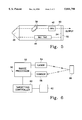
- FIG. 5 is a second embodiment of the laser arranged in accordance with the principles of the present invention.
- FIG. 6 is a block diagram for a range processing system using the laser described in the present invention.
- the laser system 10 includes a first-mirror 12 and a second mirror 14 defining the ends of an optical cavity 16.
- Mirror 12 includes an interior convex surface 18 having a radius of curvature of 10 meters which is high-reflectivity coated (approximately 100%) to reflect light having a wavelength of 1.06 microns and also high reflectivity coated (approximately 88% ??) to reflect light having a wavelength of 1.57 microns.
- Mirror 14 includes a planar interior surface 20 which is high-reflectivity coated (approximately 100%) to reflect light having a wavelength of 1.06 microns and only partially reflectivity coated (approximately 46%) at a wavelength of 1.57 microns, to thereby function as an outcoupler for the eyesafe 1.57 micron output beam.
- Mirrors 14 and 12 are separated by approximately 5 inches (14 cm). While shown as being 88% reflective of 1.57 microns, mirror 12 preferably is 100% reflective of 1.57 micron light.
- a neodymium-doped yttrium aluminum garnet (Nd:YAG) rod 24 of dimensions 2.5 mm ⁇ 50 mm is flashlamp-pumped.
- both the rod 24 and the lamp are enclosed within a reflective ceramic pump cavity.
- the rod 24 provides gain for light at a wavelength of 1.06 microns.
- the Q-switch 26 initially absorbs light at 1.06 microns until a predetermined amount of energy has been absorbed. Q-switch 26 then becomes relatively transparent, thereby resulting in the onset of laser action and subsequently causing the release of stored energy as 1.06 micron light.
- Q-switch 26 is a 0.54 optical density Cr 4+ :YAG crystal oriented at its Brewster angle (61.2° ) with respect to optical axis 28 connecting the various elements of the laser resonator 10 and functions as a Brewster polarizing plate, whereby the 1.06 micron light is linearly polarized.
- the polarized 1.06 micron light after reaching sufficient intensity, is converted to 1.57 micron light by the optical parametric oscillator (OPO) 22.
- the OPO 22 includes as the active element a potassium titanyl phosphate (KTP) crystal having its Z-axis shown as projecting outward from the plane of FIG. 1.
- This KTP crystal orientation, as well as the orientation of the Brewster plate 26 relative to the optical axis 28, provide type 11 phase matching conditions for KTP in which the 1.06 micron input and 1.57 micron output are both linearly polarized in the plane of FIG. 1 (ie, are perpendicular to the Z-axis of the KTP).
- the optical pa+rametric oscillator 22 and Nd:YAG rod 24 share a common resonator cavity 16.
- the surfaces of rod 24 and OPO 22 are preferably anti-reflective coated to improve transmission at both 1.06 microns and 1.57 microns.
- the reflective coatings applied to interior surface 20 of mirror 14 may be directly applied to the output side of OPO 22, thereby eliminating mirror 14.
- the combined Q-switch/Brewster plate 26 was not anti-reflection coated, it would also be functional with such a coating, albeit with some loss of efficiency.
- the Nd:YAG rod 24 is flashlamp-pumped or diode-pumped.
- the 1.06 micron light is Q-switched using a low transmittance 0.54 optical density tetravalent-doped chromium yttrium aluminum garnet (Cr 4+ :YAG) crystal.
- the threshold for the laser in FIG. 1 using this Q-switch is about 3.6 Joules of electrical energy input to the flashlamp.
- approximately 1 milliJoule of output energy is emitted from mirror 14 in the form of 1.57 micron light.
- FIG. 2 depicts a typical 1.57 micron pulse observed with the laser resonator of FIG. 1.
- FIG. 5 depicts an alternative embodiment of an eyesafe laser utilizing the single optical cavity concept.
- the resonator cavity 30 includes a single mirror 32 having deposited on an interior surface 34 a high reflectivity mirror coating to totally reflect the pump light at a wavelength of 1.06 microns and to partially reflect the output light at a wavelength of 1.57 microns.
- the resonator cavity 30 also includes a corner cube folding prism 36 which enables a single mirror design.
- the combined Q-switch/Brewster plate 38 is a Cr 4+ :YAG crystal extending across the upper leg of the folded resonator cavity 30.
- the Nd:YAG rod 40 is flashlamp-pumped. The rod 40 provides gain for light at a wavelength of 1.06 microns.
- Combined Q-switch/Brewster plate 38 operates as described with respect to FIG. 1 to absorb light at 1.06 microns, then release the stored energy subsequent to the onset of laser action linearly polarized in the plane of the Figure.
- OPO 42 includes a KTP crystal and converts the 1.06 micron light, after it reaches a sufficient intensity, to 1.57 micron light. The 1.57 micron light is then partially transmitted through the mirror 32 to provide an eyesafe output laser beam.
- a targeting system 50 which includes one of the laser as described in FIGS. 1 and 5.
- the targeting system 50 includes a range processor 52.
- Range processor 52 provides control signals to a laser 54, which may be any of the lasers as described with respect to FIGS. 1 and 4-6.
- the laser 54 outputs a single (or repeated) pulse directed to an object 56 which has been selected for targeting.
- the laser pulse reflects off of object 56 back in the direction of the laser 54.
- a sensor 58 detects the reflected pulse.
- the sensor 58 provides an input signal to range processor 52.
- Range processor 52 determines the distance between the laser 54/sensor 58 and the object 56.
- Range processor 52 determines the distance in accordance with the time differential between the sending of the pulse by laser 54 and the receiving of the pulse by sensor 58. Range processor 52 then computes the distance and outputs the distance to targeting controlling 60. Targeting controller 60 then determines a targeting solution in accordance with the distance provided by range processor 52 and other inputs (not shown). Targeting controller then outputs the targeting solution to a tracking device 62 whose orientation may be controlled by targeting controller 60 in accordance with the range information provided by range processor 52.
- mirrors 12 and 14, resonator cavity 16, and Nd:YAG rod 24 define a pump laser.
- the Nd:YAG rod provides the gain medium for the pump laser.
- mirror coating when a mirror coating is applied to the output side of the OPO, that mirror coating also comprises part of the pump laser.
- the rod may include one of 3 the following materials Nd, Nd 3+ , and Yb 3+ .
- nonlinear crystals may be substituted for the KTP crystal.
- acceptable substitutes may include potassium titanyl arsenate (KTA), rubidium titanyl arsenate (RTA) potassium rubidium titanyl arsenate (KRTA), and the like.
- KTA potassium titanyl arsenate
- RTA rubidium titanyl arsenate
- KRTA potassium rubidium titanyl arsenate
- These various crystals generally share the common property that they can shift an incoming wavelength to an eyesafe, typically 1 to 1-11/2 microns, in a non-critically matched phase condition but having a selection of crystal available provides greater flexibility in the design of lasers for particular applications.
- diode-pumping of the pump laser may be used as an alternative to the flash lamp-pumping, as described.
- the same optical resonator cavity may be used for both the pump laser and the optical parametric oscillator and that the same crystal may be used as both the Q-switch and as the polarizer, thereby providing a particularly simple configuration which is relatively easy to align and which operates with a relatively high efficiency.
Abstract
Description
Claims (5)
Priority Applications (11)
| Application Number | Priority Date | Filing Date | Title |
|---|---|---|---|
| US08/845,267 US5841798A (en) | 1996-05-07 | 1997-04-24 | Eyesafe laser transmitter with brewster angle Q switch in single resonator cavity for both pump laser and optical parametric oscillator |
| EP98920844A EP0907995B1 (en) | 1997-04-24 | 1998-04-14 | Laser and eyesafe laser transmitter |
| IL12752798A IL127527A (en) | 1997-04-24 | 1998-04-14 | Eyesafe laser transmitter with brewster angle q-switch in single resonator cavity for both pump laser and optical parametric oscillator |
| JP54616298A JP3410108B2 (en) | 1997-04-24 | 1998-04-14 | A range finding system using an eye-safe laser with a Brewster angle Q-switch in a single cavity cavity of both the pump laser and the optical parametric oscillator |
| KR1019980710555A KR100281832B1 (en) | 1997-04-24 | 1998-04-14 | Eyesafe laser transmitter |
| CA002258887A CA2258887C (en) | 1997-04-24 | 1998-04-14 | Eyesafe laser transmitter |
| IL14395998A IL143959A (en) | 1997-04-24 | 1998-04-14 | Eyesafe laser transmitter with brewster angle q-switch in single resonator cavity for both pump laser and optical parametric oscillator |
| PCT/US1998/007653 WO1998048493A1 (en) | 1997-04-24 | 1998-04-14 | Eyesafe laser transmitter |
| ES98920844T ES2166602T3 (en) | 1997-04-24 | 1998-04-14 | LASER AND LASER TRANSMITTER SAFE FOR THE VIEW. |
| US09/136,634 US5991012A (en) | 1996-05-07 | 1998-08-19 | Eyesafe laser transmitter with brewster angle Q-switch in single resonator cavity for both pump laser and optical parametric oscillator |
| NO986057A NO986057L (en) | 1997-04-24 | 1998-12-22 | Eye-safe laser transmitter with Brewster angle Q switch in a single resonator cavity for both pump lasers and optical parametric oscillator |
Applications Claiming Priority (2)
| Application Number | Priority Date | Filing Date | Title |
|---|---|---|---|
| US08/646,200 US5687186A (en) | 1996-05-07 | 1996-05-07 | Eyesafe laser transmitter with single resonator cavity for both pump laser and optical parametric oscillator |
| US08/845,267 US5841798A (en) | 1996-05-07 | 1997-04-24 | Eyesafe laser transmitter with brewster angle Q switch in single resonator cavity for both pump laser and optical parametric oscillator |
Related Parent Applications (1)
| Application Number | Title | Priority Date | Filing Date |
|---|---|---|---|
| US08/646,200 Continuation-In-Part US5687186A (en) | 1996-05-07 | 1996-05-07 | Eyesafe laser transmitter with single resonator cavity for both pump laser and optical parametric oscillator |
Related Child Applications (1)
| Application Number | Title | Priority Date | Filing Date |
|---|---|---|---|
| US09/136,634 Division US5991012A (en) | 1996-05-07 | 1998-08-19 | Eyesafe laser transmitter with brewster angle Q-switch in single resonator cavity for both pump laser and optical parametric oscillator |
Publications (1)
| Publication Number | Publication Date |
|---|---|
| US5841798A true US5841798A (en) | 1998-11-24 |
Family
ID=25294811
Family Applications (2)
| Application Number | Title | Priority Date | Filing Date |
|---|---|---|---|
| US08/845,267 Expired - Lifetime US5841798A (en) | 1996-05-07 | 1997-04-24 | Eyesafe laser transmitter with brewster angle Q switch in single resonator cavity for both pump laser and optical parametric oscillator |
| US09/136,634 Expired - Lifetime US5991012A (en) | 1996-05-07 | 1998-08-19 | Eyesafe laser transmitter with brewster angle Q-switch in single resonator cavity for both pump laser and optical parametric oscillator |
Family Applications After (1)
| Application Number | Title | Priority Date | Filing Date |
|---|---|---|---|
| US09/136,634 Expired - Lifetime US5991012A (en) | 1996-05-07 | 1998-08-19 | Eyesafe laser transmitter with brewster angle Q-switch in single resonator cavity for both pump laser and optical parametric oscillator |
Country Status (9)
| Country | Link |
|---|---|
| US (2) | US5841798A (en) |
| EP (1) | EP0907995B1 (en) |
| JP (1) | JP3410108B2 (en) |
| KR (1) | KR100281832B1 (en) |
| CA (1) | CA2258887C (en) |
| ES (1) | ES2166602T3 (en) |
| IL (1) | IL127527A (en) |
| NO (1) | NO986057L (en) |
| WO (1) | WO1998048493A1 (en) |
Cited By (11)
| Publication number | Priority date | Publication date | Assignee | Title |
|---|---|---|---|---|
| US6272274B1 (en) * | 1996-11-28 | 2001-08-07 | Electro Optic Systems Pty Lim | Optical transmitting and receiving system |
| US6650682B1 (en) | 1999-04-30 | 2003-11-18 | University Of New Mexico | Bi-directional short pulse ring laser |
| US20050232328A1 (en) * | 2004-03-30 | 2005-10-20 | Mitsubishi Denki Kabushiki Kaisha | Solid-state laser system |
| US20060171429A1 (en) * | 2005-01-28 | 2006-08-03 | Seitel Steven C | Monoblock laser with reflective substrate |
| US20060280221A1 (en) * | 2005-03-17 | 2006-12-14 | Seitel Steven C | Monoblock laser with improved alignment features |
| US7839904B1 (en) | 2006-01-26 | 2010-11-23 | Scientific Materials Corporation | Monoblock laser systems and methods |
| US9281652B1 (en) * | 2012-06-25 | 2016-03-08 | Nlight Photonics Corporation | Unstable OPO resonators with improved beam quality |
| WO2017180623A1 (en) * | 2016-04-11 | 2017-10-19 | Ipg Photonics Corporation | Handheld analyzer and method for measuring elemental concentration |
| US20190319714A1 (en) * | 2018-04-12 | 2019-10-17 | Raytheon Company | Phase change detection in optical signals |
| US10729496B2 (en) | 2017-11-21 | 2020-08-04 | Cutera, Inc. | Dermatological picosecond laser treatment systems and methods using optical parametric oscillator |
| US11400308B2 (en) | 2017-11-21 | 2022-08-02 | Cutera, Inc. | Dermatological picosecond laser treatment systems and methods using optical parametric oscillator |
Families Citing this family (3)
| Publication number | Priority date | Publication date | Assignee | Title |
|---|---|---|---|---|
| US6373865B1 (en) * | 2000-02-01 | 2002-04-16 | John E. Nettleton | Pseudo-monolithic laser with an intracavity optical parametric oscillator |
| JP5551722B2 (en) * | 2006-08-29 | 2014-07-16 | ギガフォトン株式会社 | Driver laser for extreme ultraviolet light source device |
| KR100764424B1 (en) * | 2006-08-30 | 2007-10-05 | 삼성전기주식회사 | Wavelength converted laser apparatus and nonlinear optical crystal used in same |
Citations (2)
| Publication number | Priority date | Publication date | Assignee | Title |
|---|---|---|---|---|
| US5181211A (en) * | 1991-05-20 | 1993-01-19 | Fibertek, Inc. | Eye-safe laser system |
| US5687186A (en) * | 1996-05-07 | 1997-11-11 | Hughes Electronics | Eyesafe laser transmitter with single resonator cavity for both pump laser and optical parametric oscillator |
Family Cites Families (7)
| Publication number | Priority date | Publication date | Assignee | Title |
|---|---|---|---|---|
| US5303256A (en) * | 1993-03-12 | 1994-04-12 | Hughes Aircraft Company | Quasi-monolithic saturable optical element |
| US5457707A (en) * | 1993-08-24 | 1995-10-10 | Spectra-Physics Lasers, Inc. | Master optical parametric oscillator/power optical parametric oscillator |
| US5390211A (en) * | 1993-08-24 | 1995-02-14 | Spectra-Physics Lasers, Inc. | Optical parametric oscillator with unstable resonator |
| US5377219A (en) * | 1993-10-27 | 1994-12-27 | Geiger; Allen R. | Wavelength matched OPO/OPA unit |
| US5619517A (en) * | 1995-02-01 | 1997-04-08 | Research Foundation Of The University Of Central Florida | Optical parametric oscillator with built-in seeding laser source |
| US5608744A (en) * | 1995-03-31 | 1997-03-04 | Litton Systems, Inc. | Compact laser apparatus and method |
| US5852492A (en) * | 1996-06-07 | 1998-12-22 | Lockheed Martin Vought Systems Corp. | Fused lasar range/intensity image display for a human interpretation of lasar data |
-
1997
- 1997-04-24 US US08/845,267 patent/US5841798A/en not_active Expired - Lifetime
-
1998
- 1998-04-14 IL IL12752798A patent/IL127527A/en not_active IP Right Cessation
- 1998-04-14 WO PCT/US1998/007653 patent/WO1998048493A1/en active IP Right Grant
- 1998-04-14 EP EP98920844A patent/EP0907995B1/en not_active Expired - Lifetime
- 1998-04-14 JP JP54616298A patent/JP3410108B2/en not_active Expired - Lifetime
- 1998-04-14 CA CA002258887A patent/CA2258887C/en not_active Expired - Fee Related
- 1998-04-14 KR KR1019980710555A patent/KR100281832B1/en not_active IP Right Cessation
- 1998-04-14 ES ES98920844T patent/ES2166602T3/en not_active Expired - Lifetime
- 1998-08-19 US US09/136,634 patent/US5991012A/en not_active Expired - Lifetime
- 1998-12-22 NO NO986057A patent/NO986057L/en not_active Application Discontinuation
Patent Citations (2)
| Publication number | Priority date | Publication date | Assignee | Title |
|---|---|---|---|---|
| US5181211A (en) * | 1991-05-20 | 1993-01-19 | Fibertek, Inc. | Eye-safe laser system |
| US5687186A (en) * | 1996-05-07 | 1997-11-11 | Hughes Electronics | Eyesafe laser transmitter with single resonator cavity for both pump laser and optical parametric oscillator |
Cited By (18)
| Publication number | Priority date | Publication date | Assignee | Title |
|---|---|---|---|---|
| US6272274B1 (en) * | 1996-11-28 | 2001-08-07 | Electro Optic Systems Pty Lim | Optical transmitting and receiving system |
| US6650682B1 (en) | 1999-04-30 | 2003-11-18 | University Of New Mexico | Bi-directional short pulse ring laser |
| US20050232328A1 (en) * | 2004-03-30 | 2005-10-20 | Mitsubishi Denki Kabushiki Kaisha | Solid-state laser system |
| US7336690B2 (en) * | 2004-03-30 | 2008-02-26 | Mitsubishi Denki Kabushiki Kaisha | Solid-state laser system |
| US20060171429A1 (en) * | 2005-01-28 | 2006-08-03 | Seitel Steven C | Monoblock laser with reflective substrate |
| US7729392B2 (en) | 2005-01-28 | 2010-06-01 | Scientific Materials Corporation | Monoblock laser with reflective substrate |
| US20060280221A1 (en) * | 2005-03-17 | 2006-12-14 | Seitel Steven C | Monoblock laser with improved alignment features |
| US7817704B2 (en) | 2005-03-17 | 2010-10-19 | Scientific Materials Corporation | Monoblock laser with improved alignment features |
| US7839904B1 (en) | 2006-01-26 | 2010-11-23 | Scientific Materials Corporation | Monoblock laser systems and methods |
| US9281652B1 (en) * | 2012-06-25 | 2016-03-08 | Nlight Photonics Corporation | Unstable OPO resonators with improved beam quality |
| WO2017180623A1 (en) * | 2016-04-11 | 2017-10-19 | Ipg Photonics Corporation | Handheld analyzer and method for measuring elemental concentration |
| CN109661570A (en) * | 2016-04-11 | 2019-04-19 | Ipg光子公司 | For measuring the Handheld analysis and method of concentration of element |
| EP3440450A4 (en) * | 2016-04-11 | 2019-11-20 | IPG Photonics Corporation | Handheld analyzer and method for measuring elemental concentration |
| US10729496B2 (en) | 2017-11-21 | 2020-08-04 | Cutera, Inc. | Dermatological picosecond laser treatment systems and methods using optical parametric oscillator |
| US11389237B2 (en) | 2017-11-21 | 2022-07-19 | Cutera, Inc. | Dermatological picosecond laser treatment systems and methods using optical parametric oscillator |
| US11400308B2 (en) | 2017-11-21 | 2022-08-02 | Cutera, Inc. | Dermatological picosecond laser treatment systems and methods using optical parametric oscillator |
| US20190319714A1 (en) * | 2018-04-12 | 2019-10-17 | Raytheon Company | Phase change detection in optical signals |
| US11012160B2 (en) * | 2018-04-12 | 2021-05-18 | Raytheon Company | Phase change detection in optical signals |
Also Published As
| Publication number | Publication date |
|---|---|
| ES2166602T3 (en) | 2002-04-16 |
| EP0907995B1 (en) | 2002-01-02 |
| EP0907995A1 (en) | 1999-04-14 |
| US5991012A (en) | 1999-11-23 |
| JP3410108B2 (en) | 2003-05-26 |
| IL127527A0 (en) | 1999-10-28 |
| IL127527A (en) | 2001-11-25 |
| NO986057D0 (en) | 1998-12-22 |
| KR20000022139A (en) | 2000-04-25 |
| CA2258887A1 (en) | 1998-10-29 |
| WO1998048493A1 (en) | 1998-10-29 |
| KR100281832B1 (en) | 2001-03-02 |
| NO986057L (en) | 1998-12-22 |
| JPH11514162A (en) | 1999-11-30 |
| CA2258887C (en) | 2002-06-25 |
Similar Documents
| Publication | Publication Date | Title |
|---|---|---|
| US4797893A (en) | Microlaser system | |
| EP1037338B1 (en) | Tunable high powered laser | |
| US5218610A (en) | Tunable solid state laser | |
| US5841798A (en) | Eyesafe laser transmitter with brewster angle Q switch in single resonator cavity for both pump laser and optical parametric oscillator | |
| WO1995006345A2 (en) | Deep blue microlaser | |
| US5995523A (en) | Single mode laser suitable for use in frequency multiplied applications and method | |
| US5687186A (en) | Eyesafe laser transmitter with single resonator cavity for both pump laser and optical parametric oscillator | |
| US4292602A (en) | Laser resonator | |
| KR0169538B1 (en) | Monolithic multifunctional optical elements | |
| US5502738A (en) | Polarization control element and solid-state laser system | |
| KR100269028B1 (en) | An apparatus of unidirectionally operating laser by using semi-monolithic ring cavity | |
| WO1996029765A1 (en) | Prism folded laser cavity with controlled intracavity beam polarization | |
| US4438517A (en) | Interferometrically tuned laser resonator | |
| EP0201687A2 (en) | Passive Q-switched power laser resonator | |
| IL143959A (en) | Eyesafe laser transmitter with brewster angle q-switch in single resonator cavity for both pump laser and optical parametric oscillator | |
| EP1891717A1 (en) | Frequency stabilized laser source | |
| US6320894B1 (en) | High energy Q-switched 0.9 μm laser | |
| CN116031740A (en) | RTP crystal Q-switching and Raman function composite laser and implementation mode | |
| JPH05211369A (en) | Laser diode pumping solid laser | |
| JPS6147684A (en) | Laser resonance device | |
| JPH0990450A (en) | Optical oscillator | |
| EP1281219A2 (en) | Single laser transmitter for q-switched and mode-locked vibration operation | |
| JPH11346019A (en) | Laser |
Legal Events
| Date | Code | Title | Description |
|---|---|---|---|
| AS | Assignment |
Owner name: HUGHES ELECTRONICS, CALIFORNIA Free format text: ASSIGNMENT OF ASSIGNORS INTEREST;ASSIGNORS:CHEN, TZENG S.;STULTZ, ROBERT D.;REEL/FRAME:008527/0360;SIGNING DATES FROM 19970410 TO 19970411 |
|
| STCF | Information on status: patent grant |
Free format text: PATENTED CASE |
|
| FPAY | Fee payment |
Year of fee payment: 4 |
|
| FEPP | Fee payment procedure |
Free format text: PAYOR NUMBER ASSIGNED (ORIGINAL EVENT CODE: ASPN); ENTITY STATUS OF PATENT OWNER: LARGE ENTITY |
|
| FPAY | Fee payment |
Year of fee payment: 8 |
|
| FEPP | Fee payment procedure |
Free format text: PAYER NUMBER DE-ASSIGNED (ORIGINAL EVENT CODE: RMPN); ENTITY STATUS OF PATENT OWNER: LARGE ENTITY Free format text: PAYOR NUMBER ASSIGNED (ORIGINAL EVENT CODE: ASPN); ENTITY STATUS OF PATENT OWNER: LARGE ENTITY |
|
| FPAY | Fee payment |
Year of fee payment: 12 |
|
| AS | Assignment |
Owner name: RAYTHEON COMPANY, MASSACHUSETTS Free format text: MERGER;ASSIGNOR:HE HOLDINGS, INC.;REEL/FRAME:032036/0159 Effective date: 19971217 |