US5843053A - Ostomy coupling - Google Patents
Ostomy coupling Download PDFInfo
- Publication number
- US5843053A US5843053A US08/725,868 US72586896A US5843053A US 5843053 A US5843053 A US 5843053A US 72586896 A US72586896 A US 72586896A US 5843053 A US5843053 A US 5843053A
- Authority
- US
- United States
- Prior art keywords
- ring
- coupling
- tabs
- ostomy
- limbs
- Prior art date
- Legal status (The legal status is an assumption and is not a legal conclusion. Google has not performed a legal analysis and makes no representation as to the accuracy of the status listed.)
- Expired - Lifetime
Links
Images


Classifications
-
- A—HUMAN NECESSITIES
- A61—MEDICAL OR VETERINARY SCIENCE; HYGIENE
- A61F—FILTERS IMPLANTABLE INTO BLOOD VESSELS; PROSTHESES; DEVICES PROVIDING PATENCY TO, OR PREVENTING COLLAPSING OF, TUBULAR STRUCTURES OF THE BODY, e.g. STENTS; ORTHOPAEDIC, NURSING OR CONTRACEPTIVE DEVICES; FOMENTATION; TREATMENT OR PROTECTION OF EYES OR EARS; BANDAGES, DRESSINGS OR ABSORBENT PADS; FIRST-AID KITS
- A61F5/00—Orthopaedic methods or devices for non-surgical treatment of bones or joints; Nursing devices; Anti-rape devices
- A61F5/44—Devices worn by the patient for reception of urine, faeces, catamenial or other discharge; Portable urination aids; Colostomy devices
- A61F5/445—Colostomy, ileostomy or urethrostomy devices
- A61F5/448—Means for attaching bag to seal ring
-
- A—HUMAN NECESSITIES
- A61—MEDICAL OR VETERINARY SCIENCE; HYGIENE
- A61F—FILTERS IMPLANTABLE INTO BLOOD VESSELS; PROSTHESES; DEVICES PROVIDING PATENCY TO, OR PREVENTING COLLAPSING OF, TUBULAR STRUCTURES OF THE BODY, e.g. STENTS; ORTHOPAEDIC, NURSING OR CONTRACEPTIVE DEVICES; FOMENTATION; TREATMENT OR PROTECTION OF EYES OR EARS; BANDAGES, DRESSINGS OR ABSORBENT PADS; FIRST-AID KITS
- A61F5/00—Orthopaedic methods or devices for non-surgical treatment of bones or joints; Nursing devices; Anti-rape devices
- A61F5/44—Devices worn by the patient for reception of urine, faeces, catamenial or other discharge; Portable urination aids; Colostomy devices
- A61F5/445—Colostomy, ileostomy or urethrostomy devices
- A61F2005/4486—Colostomy, ileostomy or urethrostomy devices with operable locking ring
Definitions
- This invention relates to an ostomy coupling.
- ostomy is intended to include colostomy, ileostomy, urostomy and other surgical diversion procedures.
- Ostomy couplings are used to connect and disconnect a bag for receiving a stomal discharge to and from a medical grade adhesive pad which is applied to the peristomal area of the skin of the wearer.
- Many designs of ostomy coupling are known. One which has enjoyed considerable world-wide commercial success is described and claimed in U.K. Patent No. 1,571,657.
- an ostomy device should have a double female ring structure which can interengage with a male ring.
- the male ring may be on the bag and the female ring on a skin-attachable adhesive pad, or vice-versa.
- An outer ring on the female coupling is circular and flexible and has a pair of inwardly-extending catches at opposite ends of a diameter.
- an improved design in which a first coupling member and a second coupling member are mutually interengageable and surround a region which includes a stomal orifice, the coupling also including a springy resilient ring which encircles the two coupling members and has a handle member which can be manipulated to cause the ring to be deformed such that radially-inwardly extending tabs on the ring are shifted between respective first positions in which the ring is undeformed and the tabs lock the two coupling members together and respective second positions in which the ring is deformed in such a way as to shift the tabs radially outwardly to positions where they permit separation of the two coupling parts, the ring also comprising a portion which joins the ends of two limbs of the ring, said portion being readily deformable and optionally sufficiently elastic such that the limb ends are pulled towards each other by the elasticity of said portion.
- an ostomy coupling in which a first coupling member and a second coupling member are mutually interengageable and surround a region which includes a stomal orifice, the coupling also including a springy resilient ring which encircles the two coupling members and has a handle member which can be manipulated to cause the ring to be deformed such that radially-inwardly extending tabs on the ring are shifted between respective first positions in which the ring is undeformed and the tabs lock the two coupling members together and respective second positions in which the ring is deformed in such a way as to shift the tabs radially outwardly to positions where they permit separation of the two coupling parts, the ring also comprising a means for joining the ends of two limbs of the ring, said means for joining being capable of applying a force to pull the limb ends towards each other.
- a locking ring for use in an ostomy coupling, the ring comprising two springy limbs and a joining portion.
- the joining portion is a stretchable elastic thermoplastics material and in another embodiment the joining portion is a sinuous springy resilient thread-like element.
- the limbs of the ring are made of a relatively rigid but springy plastics material, for example an acetal resin, and the tabs carried by it are provided with curved or angled ramp surfaces which, when the ring is deformed by a force tending to rotate it relative to the coupling members, causes the tabs to be withdrawn from slots so permitting the two coupling members to be separated.
- a relatively rigid but springy plastics material for example an acetal resin
- a valuable feature of the invention is that the ring is reliably maintained on the first coupling member even when the second coupling member is removed therefrom. Additionally, when the first and second coupling members are coupled together, the handle on the ring is accessible at an upper region of the coupling, and can be shifted between its two limit positions. In one of these the coupling is locked and in the other, unlocked. The manipulation needed to shift the ring in a rotary direction is simple and straightforward, and can be readily achieved even by the elderly or infirm. The ring because of its springy nature immediately springs back to its "handle top dead centre" position once the wearer of the coupling releases the handle.
- the endless ring has two limbs which together extend around about 350° and a thread of resilient plastics material joining the ends of these limbs.
- This thread material is sufficiently strongly resilient that it exerts a force on the ends of the limbs sufficient to prevent them moving apart in their normal rest position. In that position, the coupling is held closed by engagement of tabs in holes. This force can be overcome by rotating the ring relative to the body side coupling member.
- the means for joining the ends of two limbs of the ring may consist of a commonplace elastic band, each of the opposed ends of the respective limbs then being provided with a suitable hook so that the elastic band can be temporarily attached between the limb ends.
- Other suitable joining arrangements may occur to one skilled in the art.
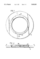
- FIG. 1 is a top view of a first coupling member in accordance with the present invention
- FIG. 2 is a side view of the first coupling member shown in FIG. 1 in partial section.
- FIG. 3 is a sectional view taken along line B--B of FIG. 1;
- FIG. 4 is a side view of a portion of the first coupling member shown in FIG. 1;
- FIG. 5 is a top view of a second coupling member in accordance with the present invention.
- FIG. 6 is a side view of the second coupling member shown in FIG. 5 in partial section;
- FIG. 7 is a sectional view of a portion of the second coupling member shown in FIG. 5;
- FIG. 8 is a top view of a locking ring in accordance with the present invention.
- FIG. 9 is a side view of the locking ring of FIG. 8 taken in the direction of the arrow E of FIG. 8;
- FIG. 10 is a cross-sectional view showing a second coupling in position for downward movement onto a first coupling and locking ring;
- FIG. 11 is a cross-sectional view showing a second coupling partly pushed downward onto a first coupling and locking ring;
- FIG. 12 is a cross-sectional view showing a second coupling coupled to a first coupling and locked together with a locking ring;
- FIG. 13 is a top view of a second embodiment of a locking ring
- FIG. 14 is a side view of the locking ring of FIG. 13 taken in the direction of the arrow E of FIG. 8;
- FIG. 15 is a top view of a third embodiment of a locking ring.
- FIG. 16 is a sectional view taken along line A--A of FIG. 15.
- the present invention has been developed with a view to meeting the need for an ostomy coupling which can be easily manipulated by old or infirm and sometimes confused persons to separate a bag side coupling from a body side coupling member which is attached to a medical grade adhesive pad.
- the invention aims to substantially avoid pressure on the tender peristomal area and to provide clear and unmistakable indications when the coupling members are (a) unlocked and ready for separation, and (b) locked together. This is a feature of importance to ostomates, who need to feel confident that no leakage will occur, and that inadvertent detachment is virtually impossible.
- Another valuable feature of the invention is that, upon the wearer releasing the handle, the ring springs back to its rest position, which may be "top dead centre” but could be a different position.
- This "automatic" return of the lock ring to its normal position is believed to be most useful in practice and to be novel in ostomy couplings.
- the wearer does not need to touch the handle when fitting a bag-side coupling to the body side coupling in place on the body; but to remove it the handle is rotated either way to an "unlock” position. Hence one can only get the bag off when the handle is held in the "unlock” positions and once the bag is off the lock automatically springs back when released, thereby ensuring automatic locking upon the fitting of the next bag.
- a preferred embodiment of a coupling according to the present invention comprises three parts, a first coupling member 10, FIGS. 1-4; a second coupling member 30, FIGS. 5 to 7; and three alternative versions 50, 70, 80 of a locking ring, FIGS. 8 and 9, FIGS. 13 and 14, and FIGS. 15 and 16.
- FIGS. 10 to 12 the bag side coupling member 30 in use is presented to and engaged with the body side coupling member 10 which is attached to the peristomal area in the normal way.
- the member 30 is pushed into the body side member 10 as shown by the arrow.
- FIG. 9 shows an intermediate stage in the coupling operation; the ring 50 has been deformed so that a limb thereof is shifted radially outwardly as the part 30 slides past the chamfer on the tab 52 of the ring 50.
- FIG. 10 shows the completion of the action; ring 50 springs back into the recess 38 in the part 30 and holds the two coupling members locked together. Uncoupling is effected by a rotational movement of the ring 50 achieved by pushing the handle portion of the ring to rotate the ring, as will be explained in more detail later in this specification.
- the first coupling member 10 will usually be the body side coupling member, and the second, the bag side member.
- the first coupling member could be the bag side member and the second coupling member could be the body side member, although this arrangement is currently less preferred.
- the body side coupling member 10 may be an injection moulding made of high or low density polyethylene, or EVA, and comprises a flange 12 having a surface 14 which in practice is attached in any suitable way such as by adhesive or by heat or RF or ultrasonic welding to a pad of medical grade adhesive.
- the purpose of such a medical grade adhesive pad is to attach the ostomy appliance to the skin of the wearer.
- the pad comprises a base which is preferably a thin film of polymeric material such as polyethylene and an adhesive layer situated on the rear surface of a base.
- Such an adhesive layer is preferably formed as a homogeneous blend of one or more pressure-sensitive viscous or elastomeric materials having intermittently dispersed therein one or more water-soluble or swellable hydrocolloid gums and may also include one or more thermoplastic elastomers and/or one or more swellable cohesive strengthening agents. Medical grade adhesive pads of other compositions may alternatively be used.
- the body side coupling member 10 has a peripheral wall 16, which as seen in FIG. 2 is circular with apertures 18A, 18B and 18C therein. As shown, there are three apertures but in a presently-preferred design of body side coupling, there are four apertures, each receiving one of the four tabs illustrated in FIG. 8 or FIG. 13.
- the aperture 18A at the top of the coupling member (in normal position of wear) subtends about 65°, and each of the apertures 18B and 18C subtends about 50°. In one embodiment in which there are four apertures, they would be located at 90° centres, and each aperture would subtend about 30°, although apertures of other extent or other position could be used.
- first and second coupling members are generally circular in form
- the invention is not considered to be limited to this, and the coupling members instead could be oval or other closed-loop shape.
- circular coupling members are referred to.
- the wall 16 is upstanding from the flange 12.
- a further flange 17 extends radially outwardly from the wall 16.
- a continuous, optionally resilient, deflectable sealing strip 20 (FIG. 4) which extends around the stomal orifice 60.
- the chief function of this strip is to inhibit leakage but it also serves to accommodate tolerances if during moulding of the coupling members, some slight divergence from the designed dimensions should occur.
- the ring 50 is depicted in FIG. 8 in its normal or unstressed condition. It comprises a handle 53 and four inwardly projecting tabs, 54A, 54B, 54C and 54D.
- the tabs are located around the ring at about 90 degree spacing, as shown.
- the tabs 54 project inwardly from an inner surface of the ring 50 and are integral with it. The extent of inward projection is determined according to the radius of the ring.
- ostomy couplings are made in various sizes, ranging from about 32 millimetres to about 57 millimetres or more. The larger sizes would be used post-operatively, and would have tabs which are wider in the radial direction.
- the handle 51 When it is desired to unlock the coupling and thereby release the bag side member so that it may be axially drawn off the body side coupling member, the handle 51 is rotated a short distance, e.g. up to about 15°, in either rotary direction away from its central position.
- the tabs 54 are shifted circumferentially in one or other rotary direction, and a surface of each tab rides up on the edge of the corresponding aperture 18 seen in FIG. 2.
- the tabs are forced in directions approximately radially outwardly, this being permitted by the springy nature of the material of the ring 50.
- ring 70 is made of two limbs 71 of acetal resin (or like springy plastics) and a joining portion 72 of a plastics elastomer whose thickness is substantially equal to the thickness of the limbs 71 but whose width (radial extent) is slightly less than that of the limbs 71.
- the plastics elastomer chosen is such that it is stretchable to up to about 150 per cent of its length at rest.
- the joining portion 72 could alternatively be made of rubber or synthetic rubber.
- the present invention can be employed in a design of ostomy coupling which is has a body-side member which includes an annular channel.
- One such design is shown in European Patent Application No. 96302557.2.
- the present invention could be employed in this design simply by including a springy or elastic joining portion located between and joined to the ends 23, 24 of the split ring 20 shown in FIG. 3 of the said European Patent Application. Such a modification would increase the security provided by the ring 20.
- the ring can be made to automatically spring back towards top dead centre position when the wearer releases his/her grip of the handle. While a ring having four tabs is currently preferred, three or five or any other convenient number could be employed.
Abstract
Description
Claims (9)
Applications Claiming Priority (2)
| Application Number | Priority Date | Filing Date | Title |
|---|---|---|---|
| GB9617410A GB2316317B (en) | 1996-08-20 | 1996-08-20 | An ostomy coupling |
| GB9617410 | 1996-08-20 |
Publications (1)
| Publication Number | Publication Date |
|---|---|
| US5843053A true US5843053A (en) | 1998-12-01 |
Family
ID=10798680
Family Applications (1)
| Application Number | Title | Priority Date | Filing Date |
|---|---|---|---|
| US08/725,868 Expired - Lifetime US5843053A (en) | 1996-08-20 | 1996-10-04 | Ostomy coupling |
Country Status (4)
| Country | Link |
|---|---|
| US (1) | US5843053A (en) |
| AU (1) | AU722363B2 (en) |
| CA (1) | CA2186656C (en) |
| ZA (1) | ZA968281B (en) |
Cited By (32)
| Publication number | Priority date | Publication date | Assignee | Title |
|---|---|---|---|---|
| US6328721B1 (en) * | 1999-06-29 | 2001-12-11 | Joseph Prohaska | Ostomy support belt |
| WO2002009629A1 (en) * | 2000-07-31 | 2002-02-07 | Biotap A/S | A clamp for detachable mounting of a device on a preferably annular implant by means of a clamping force |
| US6709422B2 (en) * | 2000-01-07 | 2004-03-23 | Biotap A/S | Ostomy bag with coupling |
| US20070005032A1 (en) * | 2003-09-18 | 2007-01-04 | Nicolas Shan | Connecting ostomy device |
| US7377278B2 (en) | 2003-06-05 | 2008-05-27 | Portaero, Inc. | Intra-thoracic collateral ventilation bypass system and method |
| US7398782B2 (en) | 2004-11-19 | 2008-07-15 | Portaero, Inc. | Method for pulmonary drug delivery |
| US7406963B2 (en) | 2006-01-17 | 2008-08-05 | Portaero, Inc. | Variable resistance pulmonary ventilation bypass valve and method |
| US7421743B1 (en) * | 2007-08-29 | 2008-09-09 | Wixom David V | Ostomy garment apparatus |
| US7426929B2 (en) | 2003-05-20 | 2008-09-23 | Portaero, Inc. | Intra/extra-thoracic collateral ventilation bypass system and method |
| US7533667B2 (en) | 2003-05-29 | 2009-05-19 | Portaero, Inc. | Methods and devices to assist pulmonary decompression |
| US20090299309A1 (en) * | 2008-05-30 | 2009-12-03 | Marlen Manufacturing & Development Co., Inc. | Locating flange for a two-piece ostomy adhesive mount |
| US7682332B2 (en) | 2003-07-15 | 2010-03-23 | Portaero, Inc. | Methods to accelerate wound healing in thoracic anastomosis applications |
| US20100191202A1 (en) * | 2007-03-15 | 2010-07-29 | B. Braun Medical Sas | Connector for an ostomy apparatus, and ostomy apparatus including same |
| US7811274B2 (en) | 2003-05-07 | 2010-10-12 | Portaero, Inc. | Method for treating chronic obstructive pulmonary disease |
| US7824366B2 (en) | 2004-12-10 | 2010-11-02 | Portaero, Inc. | Collateral ventilation device with chest tube/evacuation features and method |
| US7896008B2 (en) | 2003-06-03 | 2011-03-01 | Portaero, Inc. | Lung reduction system |
| US7909803B2 (en) | 2008-02-19 | 2011-03-22 | Portaero, Inc. | Enhanced pneumostoma management device and methods for treatment of chronic obstructive pulmonary disease |
| US7931641B2 (en) | 2007-05-11 | 2011-04-26 | Portaero, Inc. | Visceral pleura ring connector |
| US8062315B2 (en) | 2007-05-17 | 2011-11-22 | Portaero, Inc. | Variable parietal/visceral pleural coupling |
| US8104474B2 (en) | 2005-08-23 | 2012-01-31 | Portaero, Inc. | Collateral ventilation bypass system with retention features |
| US8163034B2 (en) | 2007-05-11 | 2012-04-24 | Portaero, Inc. | Methods and devices to create a chemically and/or mechanically localized pleurodesis |
| US8220460B2 (en) | 2004-11-19 | 2012-07-17 | Portaero, Inc. | Evacuation device and method for creating a localized pleurodesis |
| US8336540B2 (en) | 2008-02-19 | 2012-12-25 | Portaero, Inc. | Pneumostoma management device and method for treatment of chronic obstructive pulmonary disease |
| US8347881B2 (en) | 2009-01-08 | 2013-01-08 | Portaero, Inc. | Pneumostoma management device with integrated patency sensor and method |
| US8475389B2 (en) | 2008-02-19 | 2013-07-02 | Portaero, Inc. | Methods and devices for assessment of pneumostoma function |
| US8518053B2 (en) | 2009-02-11 | 2013-08-27 | Portaero, Inc. | Surgical instruments for creating a pneumostoma and treating chronic obstructive pulmonary disease |
| US20140194844A1 (en) * | 2011-08-29 | 2014-07-10 | Coloplast A/S | Ostomy Base Plate Having Discreet Pulling Tab |
| US8945076B2 (en) | 2011-08-03 | 2015-02-03 | Hollister Incorporated | Ostomy appliance with integrated belt tabs |
| US20150126946A1 (en) * | 2013-09-26 | 2015-05-07 | Luis Fernandez | Ostomy bag |
| US20180000628A1 (en) * | 2015-03-18 | 2018-01-04 | Multi-Lock Aps | Ostomy device |
| US20220401250A1 (en) * | 2020-02-20 | 2022-12-22 | Convatec Limited | Ostomy appliance coupling assembly |
| US11590016B1 (en) * | 2020-01-28 | 2023-02-28 | Kayal Medical Products LLC | Ostomy system |
Citations (13)
| Publication number | Priority date | Publication date | Assignee | Title |
|---|---|---|---|---|
| US1562102A (en) * | 1925-01-23 | 1925-11-17 | Massena William H Le | Bottle-cover holder |
| US1840021A (en) * | 1931-04-02 | 1932-01-05 | Winfred M Brooks | Closure |
| EP0381393A1 (en) * | 1989-02-03 | 1990-08-08 | E.R. SQUIBB & SONS, INC. | Ostomy coupling |
| WO1991001118A1 (en) * | 1989-07-21 | 1991-02-07 | Coloplast A/S | An ostomy coupling |
| EP0433102A1 (en) * | 1989-11-13 | 1991-06-19 | B. Braun Biotrol | Ostomy coupling |
| US5026360A (en) * | 1989-06-27 | 1991-06-25 | E. R. Squibb & Sons | Clamping systems for two piece ostomy device |
| GB2259342A (en) * | 1991-09-04 | 1993-03-10 | Rasmussen Gmbh | A coupling for connecting a tube to a pipe |
| GB2261376A (en) * | 1991-10-22 | 1993-05-19 | Simpla Plastics | An annular connector |
| US5364379A (en) * | 1990-06-08 | 1994-11-15 | Laboratoires Biotrol | Stoma equipment |
| GB2289221A (en) * | 1994-05-06 | 1995-11-15 | Squibb & Sons Inc | Ostomy coupling |
| US5647861A (en) * | 1995-04-13 | 1997-07-15 | E. R. Squibb & Sons, Inc. | Ostomy coupling |
| US5662628A (en) * | 1995-04-13 | 1997-09-02 | E. R. Squibb & Sons, Inc. | Coupling |
| US5693036A (en) * | 1992-05-12 | 1997-12-02 | E. R. Squibb & Sons Inc. | Method of injection moulding an undercut formation on a circular body and a closure assembly including a coupling element |
-
1996
- 1996-09-27 CA CA002186656A patent/CA2186656C/en not_active Expired - Fee Related
- 1996-10-01 AU AU67935/96A patent/AU722363B2/en not_active Ceased
- 1996-10-02 ZA ZA9608281A patent/ZA968281B/en unknown
- 1996-10-04 US US08/725,868 patent/US5843053A/en not_active Expired - Lifetime
Patent Citations (18)
| Publication number | Priority date | Publication date | Assignee | Title |
|---|---|---|---|---|
| US1562102A (en) * | 1925-01-23 | 1925-11-17 | Massena William H Le | Bottle-cover holder |
| US1840021A (en) * | 1931-04-02 | 1932-01-05 | Winfred M Brooks | Closure |
| EP0381393A1 (en) * | 1989-02-03 | 1990-08-08 | E.R. SQUIBB & SONS, INC. | Ostomy coupling |
| US5026360A (en) * | 1989-06-27 | 1991-06-25 | E. R. Squibb & Sons | Clamping systems for two piece ostomy device |
| US5322522A (en) * | 1989-07-21 | 1994-06-21 | Coloplast A/S | Locking ring for an ostomy coupling |
| WO1991001118A1 (en) * | 1989-07-21 | 1991-02-07 | Coloplast A/S | An ostomy coupling |
| EP0572378B1 (en) * | 1989-07-21 | 1994-10-05 | Coloplast A/S | An ostomy coupling |
| US5322523A (en) * | 1989-07-21 | 1994-06-21 | Coloplast A/S | Ostomy coupling |
| EP0433102A1 (en) * | 1989-11-13 | 1991-06-19 | B. Braun Biotrol | Ostomy coupling |
| US5180377A (en) * | 1989-11-13 | 1993-01-19 | Laboratoires Biotrol | Ostomy appliance |
| US5364379A (en) * | 1990-06-08 | 1994-11-15 | Laboratoires Biotrol | Stoma equipment |
| GB2259342A (en) * | 1991-09-04 | 1993-03-10 | Rasmussen Gmbh | A coupling for connecting a tube to a pipe |
| GB2261376A (en) * | 1991-10-22 | 1993-05-19 | Simpla Plastics | An annular connector |
| US5693036A (en) * | 1992-05-12 | 1997-12-02 | E. R. Squibb & Sons Inc. | Method of injection moulding an undercut formation on a circular body and a closure assembly including a coupling element |
| GB2289221A (en) * | 1994-05-06 | 1995-11-15 | Squibb & Sons Inc | Ostomy coupling |
| US5647861A (en) * | 1995-04-13 | 1997-07-15 | E. R. Squibb & Sons, Inc. | Ostomy coupling |
| US5662629A (en) * | 1995-04-13 | 1997-09-02 | E.R. Squibb & Sons, Inc. | Ostomy coupling |
| US5662628A (en) * | 1995-04-13 | 1997-09-02 | E. R. Squibb & Sons, Inc. | Coupling |
Cited By (59)
| Publication number | Priority date | Publication date | Assignee | Title |
|---|---|---|---|---|
| US6328721B1 (en) * | 1999-06-29 | 2001-12-11 | Joseph Prohaska | Ostomy support belt |
| US6709422B2 (en) * | 2000-01-07 | 2004-03-23 | Biotap A/S | Ostomy bag with coupling |
| WO2002009629A1 (en) * | 2000-07-31 | 2002-02-07 | Biotap A/S | A clamp for detachable mounting of a device on a preferably annular implant by means of a clamping force |
| US8029492B2 (en) | 2003-05-07 | 2011-10-04 | Portaero, Inc. | Method for treating chronic obstructive pulmonary disease |
| US7828789B2 (en) | 2003-05-07 | 2010-11-09 | Portaero, Inc. | Device and method for creating a localized pleurodesis and treating a lung through the localized pleurodesis |
| US7811274B2 (en) | 2003-05-07 | 2010-10-12 | Portaero, Inc. | Method for treating chronic obstructive pulmonary disease |
| US7789083B2 (en) | 2003-05-20 | 2010-09-07 | Portaero, Inc. | Intra/extra thoracic system for ameliorating a symptom of chronic obstructive pulmonary disease |
| US7426929B2 (en) | 2003-05-20 | 2008-09-23 | Portaero, Inc. | Intra/extra-thoracic collateral ventilation bypass system and method |
| US7533667B2 (en) | 2003-05-29 | 2009-05-19 | Portaero, Inc. | Methods and devices to assist pulmonary decompression |
| US7896008B2 (en) | 2003-06-03 | 2011-03-01 | Portaero, Inc. | Lung reduction system |
| US7377278B2 (en) | 2003-06-05 | 2008-05-27 | Portaero, Inc. | Intra-thoracic collateral ventilation bypass system and method |
| US7753052B2 (en) | 2003-06-05 | 2010-07-13 | Portaero, Inc. | Intra-thoracic collateral ventilation bypass system |
| US7682332B2 (en) | 2003-07-15 | 2010-03-23 | Portaero, Inc. | Methods to accelerate wound healing in thoracic anastomosis applications |
| US8323230B2 (en) | 2003-07-15 | 2012-12-04 | Portaero, Inc. | Methods and devices to accelerate wound healing in thoracic anastomosis applications |
| US7422578B2 (en) * | 2003-09-18 | 2008-09-09 | B. Braun Medical Sas | Connecting ostomy device |
| US20070005032A1 (en) * | 2003-09-18 | 2007-01-04 | Nicolas Shan | Connecting ostomy device |
| US8220460B2 (en) | 2004-11-19 | 2012-07-17 | Portaero, Inc. | Evacuation device and method for creating a localized pleurodesis |
| US7398782B2 (en) | 2004-11-19 | 2008-07-15 | Portaero, Inc. | Method for pulmonary drug delivery |
| US7824366B2 (en) | 2004-12-10 | 2010-11-02 | Portaero, Inc. | Collateral ventilation device with chest tube/evacuation features and method |
| US8104474B2 (en) | 2005-08-23 | 2012-01-31 | Portaero, Inc. | Collateral ventilation bypass system with retention features |
| US7686013B2 (en) | 2006-01-17 | 2010-03-30 | Portaero, Inc. | Variable resistance pulmonary ventilation bypass valve |
| US7726305B2 (en) | 2006-01-17 | 2010-06-01 | Portaero, Inc. | Variable resistance pulmonary ventilation bypass valve |
| US7406963B2 (en) | 2006-01-17 | 2008-08-05 | Portaero, Inc. | Variable resistance pulmonary ventilation bypass valve and method |
| US20100191202A1 (en) * | 2007-03-15 | 2010-07-29 | B. Braun Medical Sas | Connector for an ostomy apparatus, and ostomy apparatus including same |
| US8163034B2 (en) | 2007-05-11 | 2012-04-24 | Portaero, Inc. | Methods and devices to create a chemically and/or mechanically localized pleurodesis |
| US7931641B2 (en) | 2007-05-11 | 2011-04-26 | Portaero, Inc. | Visceral pleura ring connector |
| US8062315B2 (en) | 2007-05-17 | 2011-11-22 | Portaero, Inc. | Variable parietal/visceral pleural coupling |
| US7421743B1 (en) * | 2007-08-29 | 2008-09-09 | Wixom David V | Ostomy garment apparatus |
| US8453637B2 (en) | 2008-02-19 | 2013-06-04 | Portaero, Inc. | Pneumostoma management system for treatment of chronic obstructive pulmonary disease |
| US7909803B2 (en) | 2008-02-19 | 2011-03-22 | Portaero, Inc. | Enhanced pneumostoma management device and methods for treatment of chronic obstructive pulmonary disease |
| US8453638B2 (en) | 2008-02-19 | 2013-06-04 | Portaero, Inc. | One-piece pneumostoma management system and methods for treatment of chronic obstructive pulmonary disease |
| US8231581B2 (en) | 2008-02-19 | 2012-07-31 | Portaero, Inc. | Enhanced pneumostoma management device and methods for treatment of chronic obstructive pulmonary disease |
| US8252003B2 (en) | 2008-02-19 | 2012-08-28 | Portaero, Inc. | Surgical instruments for creating a pneumostoma and treating chronic obstructive pulmonary disease |
| US7927324B2 (en) | 2008-02-19 | 2011-04-19 | Portaero, Inc. | Aspirator and method for pneumostoma management |
| US8506577B2 (en) | 2008-02-19 | 2013-08-13 | Portaero, Inc. | Two-phase surgical procedure for creating a pneumostoma to treat chronic obstructive pulmonary disease |
| US8336540B2 (en) | 2008-02-19 | 2012-12-25 | Portaero, Inc. | Pneumostoma management device and method for treatment of chronic obstructive pulmonary disease |
| US8348906B2 (en) | 2008-02-19 | 2013-01-08 | Portaero, Inc. | Aspirator for pneumostoma management |
| US8347880B2 (en) | 2008-02-19 | 2013-01-08 | Potaero, Inc. | Pneumostoma management system with secretion management features for treatment of chronic obstructive pulmonary disease |
| US8491602B2 (en) | 2008-02-19 | 2013-07-23 | Portaero, Inc. | Single-phase surgical procedure for creating a pneumostoma to treat chronic obstructive pulmonary disease |
| US8365722B2 (en) | 2008-02-19 | 2013-02-05 | Portaero, Inc. | Multi-layer pneumostoma management system and methods for treatment of chronic obstructive pulmonary disease |
| US8430094B2 (en) | 2008-02-19 | 2013-04-30 | Portaero, Inc. | Flexible pneumostoma management system and methods for treatment of chronic obstructive pulmonary disease |
| US8021320B2 (en) | 2008-02-19 | 2011-09-20 | Portaero, Inc. | Self-sealing device and method for delivery of a therapeutic agent through a pneumostoma |
| US8474449B2 (en) | 2008-02-19 | 2013-07-02 | Portaero, Inc. | Variable length pneumostoma management system for treatment of chronic obstructive pulmonary disease |
| US8464708B2 (en) | 2008-02-19 | 2013-06-18 | Portaero, Inc. | Pneumostoma management system having a cosmetic and/or protective cover |
| US8475389B2 (en) | 2008-02-19 | 2013-07-02 | Portaero, Inc. | Methods and devices for assessment of pneumostoma function |
| US20090299309A1 (en) * | 2008-05-30 | 2009-12-03 | Marlen Manufacturing & Development Co., Inc. | Locating flange for a two-piece ostomy adhesive mount |
| US8328779B2 (en) * | 2008-05-30 | 2012-12-11 | Marlen Manufacturing & Development, Inc. | Locating flange for a two-piece ostomy adhesive mount |
| US8347881B2 (en) | 2009-01-08 | 2013-01-08 | Portaero, Inc. | Pneumostoma management device with integrated patency sensor and method |
| US8518053B2 (en) | 2009-02-11 | 2013-08-27 | Portaero, Inc. | Surgical instruments for creating a pneumostoma and treating chronic obstructive pulmonary disease |
| US8945076B2 (en) | 2011-08-03 | 2015-02-03 | Hollister Incorporated | Ostomy appliance with integrated belt tabs |
| US20140194844A1 (en) * | 2011-08-29 | 2014-07-10 | Coloplast A/S | Ostomy Base Plate Having Discreet Pulling Tab |
| US20150126946A1 (en) * | 2013-09-26 | 2015-05-07 | Luis Fernandez | Ostomy bag |
| US10238529B2 (en) * | 2013-09-26 | 2019-03-26 | 3 West C. LLC | Ostomy bag |
| US20180000628A1 (en) * | 2015-03-18 | 2018-01-04 | Multi-Lock Aps | Ostomy device |
| US11083617B2 (en) * | 2015-03-18 | 2021-08-10 | Multi-Lock Aps | Ostomy device |
| US11590016B1 (en) * | 2020-01-28 | 2023-02-28 | Kayal Medical Products LLC | Ostomy system |
| US20220401250A1 (en) * | 2020-02-20 | 2022-12-22 | Convatec Limited | Ostomy appliance coupling assembly |
| US11801158B2 (en) * | 2020-02-20 | 2023-10-31 | Convatec Limited | Ostomy appliance coupling assembly |
| US20230346586A1 (en) * | 2020-02-20 | 2023-11-02 | Convatec Limited | Ostomy appliance coupling assembly |
Also Published As
| Publication number | Publication date |
|---|---|
| ZA968281B (en) | 1998-04-02 |
| AU722363B2 (en) | 2000-08-03 |
| CA2186656C (en) | 2007-11-06 |
| AU6793596A (en) | 1998-02-26 |
| CA2186656A1 (en) | 1998-02-21 |
Similar Documents
| Publication | Publication Date | Title |
|---|---|---|
| US5843053A (en) | Ostomy coupling | |
| US5830200A (en) | Ostomy coupling | |
| US5662628A (en) | Coupling | |
| EP1959881B1 (en) | Coupling assembly for Ostomy | |
| US20090118687A1 (en) | Set of Coupling Parts | |
| JPS63181759A (en) | Bag coupling for artificial anus | |
| EP0737456B1 (en) | Ostomy coupling | |
| CA2134148C (en) | Male incontinence device | |
| US5709674A (en) | Ostomy coupling | |
| EP0830855B1 (en) | An ostomy coupling | |
| MXPA96004536A (en) | Coupling or union hose for osto | |
| JP3737153B2 (en) | Colostomy coupling | |
| GB2301533A (en) | Ostomy coupling |
Legal Events
| Date | Code | Title | Description |
|---|---|---|---|
| AS | Assignment |
Owner name: BRISTOL-MYERS SQUIBB COMPANY, NEW YORK Free format text: ASSIGNMENT OF ASSIGNORS INTEREST;ASSIGNOR:STEER, PETER L.;REEL/FRAME:008471/0084 Effective date: 19970324 |
|
| STCF | Information on status: patent grant |
Free format text: PATENTED CASE |
|
| FPAY | Fee payment |
Year of fee payment: 4 |
|
| FPAY | Fee payment |
Year of fee payment: 8 |
|
| AS | Assignment |
Owner name: J.P. MORGAN EUROPE LIMITED, UNITED KINGDOM Free format text: SECURITY AGREEMENT;ASSIGNOR:CONVATEC INC.;REEL/FRAME:021371/0796 Effective date: 20080801 Owner name: J.P. MORGAN EUROPE LIMITED,UNITED KINGDOM Free format text: SECURITY AGREEMENT;ASSIGNOR:CONVATEC INC.;REEL/FRAME:021371/0796 Effective date: 20080801 |
|
| AS | Assignment |
Owner name: CONVATEC TECHNOLOGIES INC., NEVADA Free format text: ASSIGNMENT OF ASSIGNORS INTEREST;ASSIGNORS:BRISTOL-MYERS SQUIBB COMPANY;CONVATEC, INC.;REEL/FRAME:021754/0611 Effective date: 20081027 Owner name: CONVATEC TECHNOLOGIES INC.,NEVADA Free format text: ASSIGNMENT OF ASSIGNORS INTEREST;ASSIGNORS:BRISTOL-MYERS SQUIBB COMPANY;CONVATEC, INC.;REEL/FRAME:021754/0611 Effective date: 20081027 |
|
| AS | Assignment |
Owner name: CONVATEC INC., NEW JERSEY Free format text: RELEASE OF SECURITY INTEREST;ASSIGNOR:J.P. MORGAN EUROPE LIMITED;REEL/FRAME:021890/0786 Effective date: 20081028 Owner name: CONVATEC INC.,NEW JERSEY Free format text: RELEASE OF SECURITY INTEREST;ASSIGNOR:J.P. MORGAN EUROPE LIMITED;REEL/FRAME:021890/0786 Effective date: 20081028 |
|
| AS | Assignment |
Owner name: J.P. MORGAN EUROPE LIMITED, UNITED KINGDOM Free format text: SECURITY AGREEMENT;ASSIGNOR:CONVATEC TECHNOLOGIES INC.;REEL/FRAME:021901/0419 Effective date: 20081028 Owner name: J.P. MORGAN EUROPE LIMITED,UNITED KINGDOM Free format text: SECURITY AGREEMENT;ASSIGNOR:CONVATEC TECHNOLOGIES INC.;REEL/FRAME:021901/0419 Effective date: 20081028 |
|
| FPAY | Fee payment |
Year of fee payment: 12 |
|
| AS | Assignment |
Owner name: CONVATEC TECHNOLOGIES, INC., NEVADA Free format text: RELEASE OF SECURITY INTEREST AT 021901/0419;ASSIGNOR:J.P. MORGAN EUROPE LIMITED;REEL/FRAME:025580/0879 Effective date: 20101223 |
|
| AS | Assignment |
Owner name: JPMORGAN CHASE BANK, N.A., AS COLLATERAL AGENT, TEXAS Free format text: SECURITY AGREEMENT;ASSIGNOR:CONVATEC TECHNOLOGIES, INC.;REEL/FRAME:025591/0856 Effective date: 20101222 Owner name: JPMORGAN CHASE BANK, N.A., AS COLLATERAL AGENT, TE Free format text: SECURITY AGREEMENT;ASSIGNOR:CONVATEC TECHNOLOGIES, INC.;REEL/FRAME:025591/0856 Effective date: 20101222 |
|
| AS | Assignment |
Owner name: UNOMEDICAL LIMITED, UNITED KINGDOM Free format text: RELEASE BY SECURED PARTY;ASSIGNOR:JPMORGAN CHASE BANK, N.A.;REEL/FRAME:040543/0357 Effective date: 20161031 Owner name: CONVATEC TECHNOLOGIES, INC., NEVADA Free format text: RELEASE BY SECURED PARTY;ASSIGNOR:JPMORGAN CHASE BANK, N.A.;REEL/FRAME:040543/0357 Effective date: 20161031 Owner name: UNOMEDICAL A/S, DENMARK Free format text: RELEASE BY SECURED PARTY;ASSIGNOR:JPMORGAN CHASE BANK, N.A.;REEL/FRAME:040543/0357 Effective date: 20161031 Owner name: CONVATEC LIMITED, UNITED KINGDOM Free format text: RELEASE BY SECURED PARTY;ASSIGNOR:JPMORGAN CHASE BANK, N.A.;REEL/FRAME:040543/0357 Effective date: 20161031 |