US5844501A - Speed reducer including temperature sensing device - Google Patents
Speed reducer including temperature sensing device Download PDFInfo
- Publication number
- US5844501A US5844501A US08/620,839 US62083996A US5844501A US 5844501 A US5844501 A US 5844501A US 62083996 A US62083996 A US 62083996A US 5844501 A US5844501 A US 5844501A
- Authority
- US
- United States
- Prior art keywords
- speed reducer
- temperature
- monitoring
- temperature sensing
- sensing device
- Prior art date
- Legal status (The legal status is an assumption and is not a legal conclusion. Google has not performed a legal analysis and makes no representation as to the accuracy of the status listed.)
- Expired - Fee Related
Links
- 239000003638 chemical reducing agent Substances 0.000 title claims abstract description 84
- 239000000314 lubricant Substances 0.000 claims abstract description 36
- 239000012530 fluid Substances 0.000 claims abstract description 25
- 238000012544 monitoring process Methods 0.000 claims description 38
- 238000004891 communication Methods 0.000 claims description 16
- 230000005540 biological transmission Effects 0.000 claims description 8
- 238000000034 method Methods 0.000 claims description 6
- 238000012546 transfer Methods 0.000 claims description 5
- 238000007789 sealing Methods 0.000 claims description 3
- 230000000007 visual effect Effects 0.000 claims description 3
- 238000010168 coupling process Methods 0.000 claims description 2
- 238000005859 coupling reaction Methods 0.000 claims description 2
- 238000013480 data collection Methods 0.000 claims 2
- 230000008878 coupling Effects 0.000 claims 1
- 238000012806 monitoring device Methods 0.000 abstract description 5
- 238000011143 downstream manufacturing Methods 0.000 abstract 1
- 238000010276 construction Methods 0.000 description 7
- 239000004593 Epoxy Substances 0.000 description 3
- 238000013021 overheating Methods 0.000 description 3
- 229910001369 Brass Inorganic materials 0.000 description 1
- RYGMFSIKBFXOCR-UHFFFAOYSA-N Copper Chemical compound [Cu] RYGMFSIKBFXOCR-UHFFFAOYSA-N 0.000 description 1
- 230000009471 action Effects 0.000 description 1
- 230000000712 assembly Effects 0.000 description 1
- 238000000429 assembly Methods 0.000 description 1
- 239000010951 brass Substances 0.000 description 1
- 230000008859 change Effects 0.000 description 1
- 230000000295 complement effect Effects 0.000 description 1
- 239000010949 copper Substances 0.000 description 1
- 229910052802 copper Inorganic materials 0.000 description 1
- 238000001514 detection method Methods 0.000 description 1
- 230000004069 differentiation Effects 0.000 description 1
- 230000000694 effects Effects 0.000 description 1
- 238000007667 floating Methods 0.000 description 1
- 230000001939 inductive effect Effects 0.000 description 1
- 238000009434 installation Methods 0.000 description 1
- 239000000463 material Substances 0.000 description 1
- 238000012986 modification Methods 0.000 description 1
- 230000004048 modification Effects 0.000 description 1
- 229920000642 polymer Polymers 0.000 description 1
Images


Classifications
-
- F—MECHANICAL ENGINEERING; LIGHTING; HEATING; WEAPONS; BLASTING
- F16—ENGINEERING ELEMENTS AND UNITS; GENERAL MEASURES FOR PRODUCING AND MAINTAINING EFFECTIVE FUNCTIONING OF MACHINES OR INSTALLATIONS; THERMAL INSULATION IN GENERAL
- F16H—GEARING
- F16H57/00—General details of gearing
- F16H57/04—Features relating to lubrication or cooling or heating
- F16H57/0412—Cooling or heating; Control of temperature
-
- F—MECHANICAL ENGINEERING; LIGHTING; HEATING; WEAPONS; BLASTING
- F16—ENGINEERING ELEMENTS AND UNITS; GENERAL MEASURES FOR PRODUCING AND MAINTAINING EFFECTIVE FUNCTIONING OF MACHINES OR INSTALLATIONS; THERMAL INSULATION IN GENERAL
- F16C—SHAFTS; FLEXIBLE SHAFTS; ELEMENTS OR CRANKSHAFT MECHANISMS; ROTARY BODIES OTHER THAN GEARING ELEMENTS; BEARINGS
- F16C19/00—Bearings with rolling contact, for exclusively rotary movement
- F16C19/52—Bearings with rolling contact, for exclusively rotary movement with devices affected by abnormal or undesired conditions
- F16C19/525—Bearings with rolling contact, for exclusively rotary movement with devices affected by abnormal or undesired conditions related to temperature and heat, e.g. insulation
-
- F—MECHANICAL ENGINEERING; LIGHTING; HEATING; WEAPONS; BLASTING
- F16—ENGINEERING ELEMENTS AND UNITS; GENERAL MEASURES FOR PRODUCING AND MAINTAINING EFFECTIVE FUNCTIONING OF MACHINES OR INSTALLATIONS; THERMAL INSULATION IN GENERAL
- F16H—GEARING
- F16H59/00—Control inputs to control units of change-speed-, or reversing-gearings for conveying rotary motion
- F16H59/68—Inputs being a function of gearing status
- F16H59/72—Inputs being a function of gearing status dependent on oil characteristics, e.g. temperature, viscosity
-
- F—MECHANICAL ENGINEERING; LIGHTING; HEATING; WEAPONS; BLASTING
- F16—ENGINEERING ELEMENTS AND UNITS; GENERAL MEASURES FOR PRODUCING AND MAINTAINING EFFECTIVE FUNCTIONING OF MACHINES OR INSTALLATIONS; THERMAL INSULATION IN GENERAL
- F16C—SHAFTS; FLEXIBLE SHAFTS; ELEMENTS OR CRANKSHAFT MECHANISMS; ROTARY BODIES OTHER THAN GEARING ELEMENTS; BEARINGS
- F16C19/00—Bearings with rolling contact, for exclusively rotary movement
- F16C19/52—Bearings with rolling contact, for exclusively rotary movement with devices affected by abnormal or undesired conditions
Definitions
- the present invention relates to a system for monitoring status information regarding the operation of speed reducers or the like.
- each mechanical component may be equipped with a plurality of sensors.
- the signal information provided by the various sensors of many mechanical components may be processed at a central monitoring controller.
- dedicated transmission lines have typically been provided for each of these sensors.
- several transmission lines would generally extend between each of the mechanical components and the central monitoring facility.
- Speed reducers may be important components in some systems and may be subject to overheating.
- the present invention recognizes and addresses the foregoing disadvantages, and others, of prior art constructions and methods. Accordingly, it is an object of the present invention to provide an improved speed reducer apparatus.
- the speed reducer preferably comprises a housing rotatably supporting an input shaft and an output shaft mechanically interconnected to transfer mechanical power therebetween.
- the housing defines an interior area for containing a lubricant fluid to at least a minimum lubricant supply level when the speed reducer is in an upright position.
- the speed reducer comprises a temperature sensing device electrically connectible to an external monitoring device.
- the temperature sensing device is supported by the housing and extends at least partially into the interior area to a predetermined location.
- the predetermined location is below the minimum lubricant supply level.
- the temperature sensing device is responsive to temperature of the lubricant fluid and is configured to communicate information indicative thereof to the external monitoring device.
- the temperature sensing device is configured to detect when the lubricant fluid reaches a predetermined temperature.
- the device includes a casing extending through the housing in sealing engagement therewith.
- An appropriate temperature sensing element such as a switch or a thermocouple, is embedded in the casing such that the temperature of the lubricant fluid may be detected.
- the speed reducer includes the external monitoring device, for example a local transmitter having an output port.
- the local transmitter is in electrical communication with the temperature sensing device to receive information indicative of the temperature of the lubricant fluid.
- the local transmitter subsequently provides status information at its output port in a predetermined format.
- the status information at least in part corresponds to the temperature information.
- the speed reducer may also be provided with other sensors which provide further information to the local transmitter.
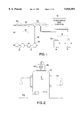
- FIG. 1 is a diagrammatic representation of a mechanical component monitoring system utilizing an improved speed reducer constructed in accordance with the invention
- FIG. 2 is a side elevation of a bearing apparatus also utilized in the monitoring system of FIG. 1;
- FIG. 3 is a partial cross sectional view as taken along line 3--3 of FIG. 2;
- FIG. 4 is a diagrammatic representation illustrating a local transmitter connected to a variety of sensor devices
- FIG. 5 is a perspective view of a first exemplary speed reducer constructed in accordance with the present invention.
- FIG. 6 is an enlarged partial cross-sectional view taken along line 6--6 showing a portion of the speed reducer shown in FIG. 5;
- FIG. 6A is a view similar to FIG. 6 illustrating certain alternative features
- FIG. 7 is a perspective view of a second exemplary speed reducer constructed in accordance with the present invention.
- FIG. 8 is an enlarged partial cross-sectional view taken along line 8--8 showing a portion of the speed reducer shown in FIG. 7, illustrating certain alternative features.
- FIG. 1 An exemplary embodiment of a mechanical component monitoring system is diagrammatically illustrated in FIG. 1.
- the system includes a processor 10 which provides monitoring and control functions for an indeterminate number of mechanical components.
- processor 10 may utilize information received from the respective mechanical components to provide diagnostic information.
- This diagnostic information can be obtained using such techniques as Fast Fourier Transform (FFT), trend line analysis or other suitable analysis techniques.
- FFT Fast Fourier Transform
- the mechanical components utilized in the monitoring system may include, for example, bearing assemblies 12 and speed reducers 14.
- Bearings 12 and speed reducers 14 each include one or more sensor devices in electrical communication with a respective local transmitter.
- the local transmitter provides status information regarding operation of the associated mechanical component to processor 10 in a predetermined format. In presently preferred embodiments, such information is transmitted to processor 10 as a serial digital word, in which portions of the word may be dedicated to information received from specific sensors.
- each of the local transmitters has a unique electronic identifier, or "address.”
- processor 10 may "interrogate” a particular local transmitter using this unique identifier.
- the local transmitter may responsively provide status information regarding the associated mechanical component.
- processor 10 will interrogate the various local transmitters of the system according to a predetermined sequence.
- electrical communication between the local transmitters and processor 10 is accomplished utilizing a bus structure having a main trunk 16 and a plurality of branch lines 18.
- Branch lines 18 are respectively connected to the bearings 12 and speed reducers 14, as shown. Connection between branch lines 18 and main trunk 16 is facilitated by a plurality of T-couplings 20.
- the principles of the described monitoring system is not limited to arrangements that utilize a "hard-wired" bus.
- various arrangements may also be provided whereby the local transmitters provide status information to processor 10 via some form of telemetry, such as radio or infrared communication.
- FIGS. 2 and 3 illustrate the construction of a bearing apparatus such as the bearings 12 of FIG. 1.
- the bearing apparatus includes a housing 22 having a bearing assembly therein for rotatably supporting a shaft 24.
- housing 22 is configured as a pillow block housing mounted to a stationary surface 26. It should be appreciated, however, that other suitable housing configurations, such as flange housings, may also be utilized.
- the bearing assembly located within housing 22 includes an annular inner ring 28 appropriately secured to shaft 24.
- Inner ring 28 defines an inner raceway about its outer circumferential surface.
- An annular outer ring 30 is further provided having an outer raceway situated in opposition to the inner raceway.
- a plurality of bearing elements, such as roller bearings 32, are disposed between the inner raceway and the outer raceway to facilitate relative rotation between rings 28 and 30. While roller bearings are illustrated, it should be appreciated that other suitable types of bearing elements, such as ball bearings, may also be utilized for this purpose.
- the local transmitter may be constructed as a single printed circuit card 34 having various components mounted thereon.
- a cover 36 in this case a small housing, may be provided to protect card 34 during use.
- card 34 is "potted" within cover 36 to provide an even greater degree of protection.
- card 34 may actually be embedded within an epoxy 38 or other suitable polymeric compound which fills the inner cavity of cover 36.
- Cover 36 may be attached to the exterior of housing 22 by bolts 40, or other suitable attachment means.
- the bearing apparatus in this case includes a speed sensor 42, a temperature sensor 44 and an accelerometer 46.
- Each of these sensors is preferably located within housing 22 or under cover 36 to provide a relatively compact arrangement, as shown.
- the sensors communicate with card 34 via respective signal lines extending therebetween.
- various other sensors may also be utilized, which communicate with card 34 via the respective signal lines collectively indicated at 48.
- speed sensor 42 may be an inductive sensor operative to sense variations in its inductance produced during rotation of inner ring 28.
- a nut or clamping collar used to secure inner ring 28 to shaft 24 may also function as a detection element from which sensor 42 can read.
- temperature sensor 44 may be configured as a thermocouple sensor located within a receiving bore defined in housing 22.
- thermocouple sensor located within a receiving bore defined in housing 22. The construction of such a sensor is described in detail in U.S. Pat. No. 5,433,525, issued Jul. 18, 1995 to the present inventor, incorporated herein by reference.
- accelerometer 46 may be of a commercially available type constructed as a separate unit. This unit, like card 34, may be potted within cover 36 for protection. Accelerometer 46 contains a movable mass responsive to vibratory movement of housing 22 to produce an analogous output signal. As such, vibration of the bearing apparatus can be detected.
- One suitable accelerometer for this purpose is Model No. 327MII, marketed by IMI of Depew, N.Y.
- circuitry located on card 34 receives sensor information and subsequently provides status information to the external processor.
- the status information may be transmitted in a serial digital format, in which portions of a digital word correspond to the respective sensors.
- the status information may represent actual sensor information.
- a digital word sixty-four (64) bits in length.
- eight (8) bits may be respectively dedicated to information from each of speed sensor 42, temperature sensor 44 and accelerometer 46.
- the remainder of the word will be used for identification and communication protocol and checking of the transmission.
- the local transmitter may perform at least an initial analysis of the sensor information.
- the status information would represent a processed version of the sensor information.
- the local processor may perform an FFT on the sensor information to provide some form of diagnostic data to the central processor.
- Other suitable analysis techniques such as trend line analysis, may also be utilized for this purpose.
- Card 34 provides the digital word containing the status information to a local port 49.
- branch line 18 is connected to port 49, thus establishing electrical communication with processor 10.
- port 49 is a five (5) pin port, corresponding to the five (5) lines comprising the overall bus.
- port 49 is configured such that branch line 18 may be easily connected or disconnected as desired.
- two of the five (5) lines in the bus serve to transmit signal information between card 34 and processor 10.
- Presently preferred embodiments utilize the controller area network (CAN) protocol for this purpose because it generally allows longer distance transmission than some other protocols, such as RS-232.
- CAN controller area network
- Two other lines provide operating voltage for the circuit components, e.g, floating +24 VDC in the illustrated embodiment.
- the fifth line provides case grounding (GND).
- Card 34 includes an on-board microprocessor 50 to recognize the external interrogation and provide the desired serial output.
- the output of some sensors, such as speed sensor 42, may be provided directly to microprocessor 50.
- A/D analog-to-digital
- the outputs of temperature sensor 44 and accelerometer 46 are in this case provided to respective A/D converters 52 and 54.
- Converters 52 and 54 supply a representative digital output to microprocessor 50. It should be appreciated, however, that some suitable microprocessors may have one or more internal A/D converters.
- Typical accelerometer devices such as accelerometer 46, often utilize an external power supply circuit.
- this supply circuit may be mounted directly on card 34, as indicated at 56.
- the accelerometer itself may be mounted on card 34 in some alternative embodiments.
- accelerometers have recently been developed which are incorporated into a microchip. Such a "micromachine" accelerometer is diagrammatically indicated at 58.
- sensors which may be connected to microprocessor 50 provide an on/off output.
- the devices are configured to change state (from either a normally open or a normally closed state) when the parameter of interest exceeds a predetermined threshold.
- Examples of such sensors include temperature switch 60 and proximity switch 62.
- a preferred arrangement of temperature switch 60 is shown in U.S. Pat. No. 5,439,296, issued Aug. 8, 1995 to the present inventor and incorporated herein by reference.
- pressure switch 64 Another sensor which provides an on/off signal is pressure switch 64.
- pressure switch 64 would not be utilized with a bearing, but may be incorporated into a speed reducer.
- Pressure switch 64 will function to detect when the pressure inside the reducer exceeds a predetermined value, which signals that the breather is plugged.
- FIGS. 5 through 8 illustrate preferred constructions of speed reducers in accordance with the present invention.
- a speed reducer 70 is shown having a local transmitter mounted thereon.
- Speed reducer 70 includes a housing 72 rotatably supporting an input shaft 74 and an output shaft 76.
- input shaft 74 and output shaft 76 are mechanically interconnected by various gears and the like within housing 72 to transfer mechanical power therebetween. Rotation of input shaft 74 by a source of mechanical power will thus cause a rotation of output shaft 76.
- the respective rotational speeds of shaft 74 and shaft 76 will be governed by a predetermined speed ratio.
- Speed reducer 70 further includes a temperature sensing device 78 in communication with the local transmitter (having housing 36).
- the local transmitter is mounted on the top of housing 72, remotely from temperature sensing device 78.
- the local transmitter may be mounted proximate other sensor devices, for example as illustrated above with respect to FIG. 3. Communication between the temperature sensing device 78 and the local transmitter is effected via communication lines located within conduit 80.
- the local transmitter may be mounted proximate to temperature sensing device 78, in a manner similar to that illustrated in FIG. 3.
- housing 72 defines an interior area 82 containing a lubricant fluid 84 therein.
- Lubricant fluid 84 serves to lubricate the various internal mechanical components of speed reducer 70.
- fluid 84 will remain at or above a predetermined minimum lubricant supply level, indicated at dashed line 86, when speed reducer 70 is in an upright position as shown in FIG. 5.
- Temperature sensing device 78 includes a casing 88 threadably received in the wall of housing 72 as shown.
- casing 88 includes a first threaded portion 90 engaging complementary threads in the housing wall.
- An extension portion 92 extends into interior area 82 of housing 72 to a position defined by a predetermined distance A from the housing wall.
- An integral shoulder flange 94 configured on its outer surface as a nut, defines the limit to which the casing may be threaded through the housing wall, thereby determining the distance A.
- Casing 88 further includes a second threaded portion to facilitate attachment of conduit 80.
- Casing 88 is preferably constructed of a suitable material, such as copper or brass, that can withstand relatively high operating temperatures and which also has suitable thermal conduction properties.
- temperature sensing device 78 includes a temperature switch 98 mounted within casing 88. Specifically, temperature switch 98 is mounted against the inner surface of a web portion 99 located at the end of extension portion 92. Preferably, switch 98 is maintained in position and protected by a heat resistant epoxy 100 substantially filling the entire interior cavity of casing 88.
- the thickness of web portion 99 should be relatively thin to allow easy thermal conduction to switch 98. In one embodiment, web portion 98 will have a thickness of approximately 1/16 inch.
- Temperature switch 98 may be of the type including an internal bimetallic disc such as that discussed in the above-mentioned U.S. Pat. No. 5,429,296. Upon reaching a predetermined temperature, switch 98 will either open or close, depending on the type of switch used. As a result, an indication may be received at the local transmitter that lubricant fluid 84 has become too hot. Switch 98 is electrically connected to wires 101 which provide electrical communication the local transmitter in the manner described above.
- the bimetallic disc arrangement of switch 98 is preferable because of its relative precision.
- the disc will generally "snap" in a firm manner from its normal state to its alternate state when a predetermined temperature has been reached.
- the switch does not oscillate between the on and off states as the temperature nears the predetermined temperature.
- switch 98 is of a relatively small size, enabling effective operation without excessive intrusion into interior area 82.
- the distance A is approximately 0.25 inch.
- temperature sensing device 84 may be installed at various positions on speed reducer 70 through housing 72 without danger of interference with the speed reducer's interior mechanical parts.
- the temperature sensing device may comprise various configurations.
- a thermocouple sensor as disclosed in the above-mentioned U.S. Pat. No. 5,433,525 may be used instead of switch 98.
- a temperature sensor device 102 is illustrated having a casing 104 identical to casing 88 of temperature sensor device 78.
- a thermocouple is provided having a sensing tip 106 engaging the web portion 108 of casing 104.
- the thermocouple further includes a sheath 110 that protects the thermocouple wires 112.
- the interior of casing is filled with a suitable heat resistant epoxy 114 in the manner described above.
- FIGS. 7 and 8 illustrate temperature sensing device 78 in an alternative installation on speed reducer 116.
- speed reducer 116 may be similar to speed reducer 70 described above.
- the housing 118 of speed reducer 116 is shown to have a slightly different exterior shape merely to permit differentiation in the drawings.
- device 78 is being used to monitor the temperature of lubricant 84 so that an alarm 120 may be activated when the lubricant temperature reaches or exceeds a predetermined maximum, such as a temperature indicative of overheating. More specifically, switch 98 closes upon such occurrence, thereby causing wires 101 to communicate an alarm signal to a alarm device 120, which may be an audible or visual alarm.
- junction box 126 is provided for this purpose.
- Junction box 126 includes an interior-threaded portion 128 for engaging the second threaded portion 96 of casing 88.
- junction box 126 further defines an access mouth having exterior threads 128.
- a lid 130 is provided engaging threads 128 to permit easy access to the interior of the junction box 126 for connecting or disconnection the wires.
- a depending threaded portion 132 permits attachment of conduit 134.
Abstract
Description
Claims (21)
Priority Applications (2)
| Application Number | Priority Date | Filing Date | Title |
|---|---|---|---|
| US08/620,839 US5844501A (en) | 1996-03-18 | 1996-03-18 | Speed reducer including temperature sensing device |
| EP97104569A EP0797028A3 (en) | 1996-03-18 | 1997-03-18 | Speed reducer including temperature sensing device |
Applications Claiming Priority (1)
| Application Number | Priority Date | Filing Date | Title |
|---|---|---|---|
| US08/620,839 US5844501A (en) | 1996-03-18 | 1996-03-18 | Speed reducer including temperature sensing device |
Publications (1)
| Publication Number | Publication Date |
|---|---|
| US5844501A true US5844501A (en) | 1998-12-01 |
Family
ID=24487623
Family Applications (1)
| Application Number | Title | Priority Date | Filing Date |
|---|---|---|---|
| US08/620,839 Expired - Fee Related US5844501A (en) | 1996-03-18 | 1996-03-18 | Speed reducer including temperature sensing device |
Country Status (2)
| Country | Link |
|---|---|
| US (1) | US5844501A (en) |
| EP (1) | EP0797028A3 (en) |
Cited By (18)
| Publication number | Priority date | Publication date | Assignee | Title |
|---|---|---|---|---|
| US6323619B1 (en) * | 2000-09-29 | 2001-11-27 | Reliance Electric Technologies, Llc | Condition monitoring and battery recharging system |
| WO2002027704A1 (en) * | 2000-09-28 | 2002-04-04 | Vigilos, Inc. | System and method for dynamic interaction with remote devices |
| US6405139B1 (en) * | 1998-09-15 | 2002-06-11 | Bently Nevada Corporation | System for monitoring plant assets including machinery |
| US6425293B1 (en) | 1999-03-13 | 2002-07-30 | Textron Systems Corporation | Sensor plug |
| US20020143934A1 (en) * | 2000-09-28 | 2002-10-03 | Barker Geoffrey T. | System and method for providing configurable security monitoring utilizing an integrated information system |
| US6469404B1 (en) * | 1997-11-14 | 2002-10-22 | Iws International Inc. | Intelligent control system for current distribution in a vehicle |
| US6472770B1 (en) * | 1997-11-14 | 2002-10-29 | Iws International, Inc. | Intelligent current distribution system and method for manufacturing the same |
| US6510397B1 (en) | 1999-03-13 | 2003-01-21 | Textron Systems Corporation | Method and apparatus for self-diagnosis of a sensor |
| US6546814B1 (en) | 1999-03-13 | 2003-04-15 | Textron Systems Corporation | Method and apparatus for estimating torque in rotating machinery |
| US6617845B1 (en) * | 2000-04-28 | 2003-09-09 | Rockwell Automation Technologies, Inc. | Proximity sensor resistant to environmental effects |
| US6694285B1 (en) | 1999-03-13 | 2004-02-17 | Textron System Corporation | Method and apparatus for monitoring rotating machinery |
| US20060151478A1 (en) * | 2004-05-17 | 2006-07-13 | Herzog Kenneth J | Conveyor speed monitor |
| US20080197797A1 (en) * | 2006-09-29 | 2008-08-21 | Reliance Electric Technologies, Llc | Motor having integral programmable logic controller |
| US7480715B1 (en) | 2002-01-25 | 2009-01-20 | Vig Acquisitions Ltd., L.L.C. | System and method for performing a predictive threat assessment based on risk factors |
| USRE43598E1 (en) | 2000-09-28 | 2012-08-21 | Vig Acquisitions Ltd., L.L.C. | Method and process for configuring a premises for monitoring |
| US8392552B2 (en) | 2000-09-28 | 2013-03-05 | Vig Acquisitions Ltd., L.L.C. | System and method for providing configurable security monitoring utilizing an integrated information system |
| DE102006020247B4 (en) * | 2006-04-27 | 2013-07-04 | Sew-Eurodrive Gmbh & Co. Kg | Sensor system for a transmission |
| US9057001B2 (en) | 2012-11-02 | 2015-06-16 | Rockwell Automation Technologies, Inc. | Transparent non-stick coating composition, method and apparatus |
Families Citing this family (1)
| Publication number | Priority date | Publication date | Assignee | Title |
|---|---|---|---|---|
| DE102016119764A1 (en) * | 2016-10-18 | 2018-04-19 | Knorr-Bremse Systeme für Nutzfahrzeuge GmbH | Temperature sensor, sensor device and manual transmission for commercial vehicles |
Citations (12)
| Publication number | Priority date | Publication date | Assignee | Title |
|---|---|---|---|---|
| US3969941A (en) * | 1973-11-08 | 1976-07-20 | E. Rapp Electronik Gmbh | Level detector for liquids and other flowable masses |
| US4488140A (en) * | 1982-05-17 | 1984-12-11 | Deere & Company | Clutch temperature monitor |
| JPH0285521A (en) * | 1988-09-20 | 1990-03-27 | Yanmar Diesel Engine Co Ltd | Bearing temperature measuring device for speed reduction reverser |
| US5189611A (en) * | 1987-03-13 | 1993-02-23 | Borg-Warner Automotive, Inc. | Temperature compensation technique for a continuously variable transmission control system |
| US5205172A (en) * | 1991-09-23 | 1993-04-27 | Doak Roni K | Electronic gauge for interface measurements |
| US5210704A (en) * | 1990-10-02 | 1993-05-11 | Technology International Incorporated | System for prognosis and diagnostics of failure and wearout monitoring and for prediction of life expectancy of helicopter gearboxes and other rotating equipment |
| US5433525A (en) * | 1993-08-13 | 1995-07-18 | Reliance Electric Industrial Company | Bearing housing with embedded temperature measurement device |
| US5439296A (en) * | 1993-06-04 | 1995-08-08 | Reliance Electric Industrial Company | Bearing housing with temperature switch |
| US5485491A (en) * | 1994-03-31 | 1996-01-16 | Westinghouse Electric Corporation | Online diagnostic system for rotating electrical apparatus |
| US5526112A (en) * | 1993-03-05 | 1996-06-11 | Sahagen; Armen N. | Probe for monitoring a fluid medium |
| US5559494A (en) * | 1992-12-18 | 1996-09-24 | General Motors Corporation | Transmission oil monitor system |
| US5581464A (en) * | 1992-08-14 | 1996-12-03 | Vorad Safety Systems, Inc. | Recording of operational events in an automotive vehicle |
Family Cites Families (10)
| Publication number | Priority date | Publication date | Assignee | Title |
|---|---|---|---|---|
| GB1366986A (en) * | 1972-02-15 | 1974-09-18 | Gkn Transmissions Ltd | Self propelled vehicles |
| DE2455729A1 (en) * | 1973-12-03 | 1975-06-05 | Roger Philippe Tronel | INDICATOR AND ALARM DEVICE FOR MOTOR VEHICLES |
| US4095644A (en) * | 1976-11-10 | 1978-06-20 | Reliance Electric Company | Cooling system for gear reducers |
| WO1984000406A1 (en) * | 1982-07-14 | 1984-02-02 | Shawky Shafeek Michael | Heat sensors for overheating brakes and wheels |
| GB8508384D0 (en) * | 1985-03-30 | 1985-05-09 | Giles P R | Temperature sensing alarm |
| EP0247185A1 (en) * | 1985-11-26 | 1987-12-02 | Sensor Scan, Inc. | Supervisory control system having improved memory management |
| JPH0226362A (en) * | 1988-07-12 | 1990-01-29 | Aisin Aw Co Ltd | Oil temperature detector of automatic transmission |
| ATE103427T1 (en) * | 1990-01-17 | 1994-04-15 | Siemens Ag | PROTECTIVE DEVICE FOR ELECTRICAL MACHINES. |
| FI932094A (en) * | 1993-05-07 | 1994-11-08 | Kone Oy | Cooling apparatus in the crankshaft of the crane |
| JPH07259972A (en) * | 1994-03-17 | 1995-10-13 | Nissan Diesel Motor Co Ltd | Abnormal sound preventing device for transmission |
-
1996
- 1996-03-18 US US08/620,839 patent/US5844501A/en not_active Expired - Fee Related
-
1997
- 1997-03-18 EP EP97104569A patent/EP0797028A3/en not_active Withdrawn
Patent Citations (14)
| Publication number | Priority date | Publication date | Assignee | Title |
|---|---|---|---|---|
| US3969941A (en) * | 1973-11-08 | 1976-07-20 | E. Rapp Electronik Gmbh | Level detector for liquids and other flowable masses |
| US4488140A (en) * | 1982-05-17 | 1984-12-11 | Deere & Company | Clutch temperature monitor |
| US5189611A (en) * | 1987-03-13 | 1993-02-23 | Borg-Warner Automotive, Inc. | Temperature compensation technique for a continuously variable transmission control system |
| JPH0285521A (en) * | 1988-09-20 | 1990-03-27 | Yanmar Diesel Engine Co Ltd | Bearing temperature measuring device for speed reduction reverser |
| US5210704A (en) * | 1990-10-02 | 1993-05-11 | Technology International Incorporated | System for prognosis and diagnostics of failure and wearout monitoring and for prediction of life expectancy of helicopter gearboxes and other rotating equipment |
| US5205172A (en) * | 1991-09-23 | 1993-04-27 | Doak Roni K | Electronic gauge for interface measurements |
| US5581464B1 (en) * | 1992-08-14 | 1999-02-09 | Vorad Safety Systems Inc | Recording of operational events in an automotive vehicle |
| US5581464A (en) * | 1992-08-14 | 1996-12-03 | Vorad Safety Systems, Inc. | Recording of operational events in an automotive vehicle |
| US5559494A (en) * | 1992-12-18 | 1996-09-24 | General Motors Corporation | Transmission oil monitor system |
| US5526112A (en) * | 1993-03-05 | 1996-06-11 | Sahagen; Armen N. | Probe for monitoring a fluid medium |
| US5581648A (en) * | 1993-03-05 | 1996-12-03 | Sahagen; Armen N. | Optical fiber probe for monitoring fluid medium |
| US5439296A (en) * | 1993-06-04 | 1995-08-08 | Reliance Electric Industrial Company | Bearing housing with temperature switch |
| US5433525A (en) * | 1993-08-13 | 1995-07-18 | Reliance Electric Industrial Company | Bearing housing with embedded temperature measurement device |
| US5485491A (en) * | 1994-03-31 | 1996-01-16 | Westinghouse Electric Corporation | Online diagnostic system for rotating electrical apparatus |
Cited By (28)
| Publication number | Priority date | Publication date | Assignee | Title |
|---|---|---|---|---|
| US6469404B1 (en) * | 1997-11-14 | 2002-10-22 | Iws International Inc. | Intelligent control system for current distribution in a vehicle |
| US6472770B1 (en) * | 1997-11-14 | 2002-10-29 | Iws International, Inc. | Intelligent current distribution system and method for manufacturing the same |
| US6405139B1 (en) * | 1998-09-15 | 2002-06-11 | Bently Nevada Corporation | System for monitoring plant assets including machinery |
| US6546814B1 (en) | 1999-03-13 | 2003-04-15 | Textron Systems Corporation | Method and apparatus for estimating torque in rotating machinery |
| US6694285B1 (en) | 1999-03-13 | 2004-02-17 | Textron System Corporation | Method and apparatus for monitoring rotating machinery |
| US6425293B1 (en) | 1999-03-13 | 2002-07-30 | Textron Systems Corporation | Sensor plug |
| US6510397B1 (en) | 1999-03-13 | 2003-01-21 | Textron Systems Corporation | Method and apparatus for self-diagnosis of a sensor |
| US6617845B1 (en) * | 2000-04-28 | 2003-09-09 | Rockwell Automation Technologies, Inc. | Proximity sensor resistant to environmental effects |
| US8392552B2 (en) | 2000-09-28 | 2013-03-05 | Vig Acquisitions Ltd., L.L.C. | System and method for providing configurable security monitoring utilizing an integrated information system |
| US8700769B2 (en) | 2000-09-28 | 2014-04-15 | Vig Acquisitions Ltd., L.L.C. | System and method for providing configurable security monitoring utilizing an integrated information system |
| WO2002027704A1 (en) * | 2000-09-28 | 2002-04-04 | Vigilos, Inc. | System and method for dynamic interaction with remote devices |
| USRE43598E1 (en) | 2000-09-28 | 2012-08-21 | Vig Acquisitions Ltd., L.L.C. | Method and process for configuring a premises for monitoring |
| US20020143934A1 (en) * | 2000-09-28 | 2002-10-03 | Barker Geoffrey T. | System and method for providing configurable security monitoring utilizing an integrated information system |
| US7627665B2 (en) | 2000-09-28 | 2009-12-01 | Barker Geoffrey T | System and method for providing configurable security monitoring utilizing an integrated information system |
| USRE45649E1 (en) | 2000-09-28 | 2015-08-11 | Vivint, Inc. | Method and process for configuring a premises for monitoring |
| US6323619B1 (en) * | 2000-09-29 | 2001-11-27 | Reliance Electric Technologies, Llc | Condition monitoring and battery recharging system |
| US7480715B1 (en) | 2002-01-25 | 2009-01-20 | Vig Acquisitions Ltd., L.L.C. | System and method for performing a predictive threat assessment based on risk factors |
| US7933989B1 (en) | 2002-01-25 | 2011-04-26 | Barker Geoffrey T | Predictive threat assessment |
| US20060273080A9 (en) * | 2004-05-17 | 2006-12-07 | Herzog Kenneth J | Conveyor speed monitor |
| US7544918B2 (en) * | 2004-05-17 | 2009-06-09 | Herzog Kenneth J | Conveyor speed monitor |
| US20060151478A1 (en) * | 2004-05-17 | 2006-07-13 | Herzog Kenneth J | Conveyor speed monitor |
| DE102006020247B4 (en) * | 2006-04-27 | 2013-07-04 | Sew-Eurodrive Gmbh & Co. Kg | Sensor system for a transmission |
| US20080197797A1 (en) * | 2006-09-29 | 2008-08-21 | Reliance Electric Technologies, Llc | Motor having integral programmable logic controller |
| US8482240B2 (en) | 2006-09-29 | 2013-07-09 | Rockwell Automation Technologies, Inc. | Motor drive having integral programmable logic controller |
| US20110025249A1 (en) * | 2006-09-29 | 2011-02-03 | Rockwell Automation Technologies, Inc. | Motor drive having integral programmable logic controller |
| US7821220B2 (en) | 2006-09-29 | 2010-10-26 | Rockwell Automation Technologies, Inc. | Motor having integral programmable logic controller |
| US9722515B2 (en) | 2006-09-29 | 2017-08-01 | Rockwell Automation Technologies, Inc. | Motor drive having integral automation controller |
| US9057001B2 (en) | 2012-11-02 | 2015-06-16 | Rockwell Automation Technologies, Inc. | Transparent non-stick coating composition, method and apparatus |
Also Published As
| Publication number | Publication date |
|---|---|
| EP0797028A3 (en) | 1998-01-07 |
| EP0797028A2 (en) | 1997-09-24 |
Similar Documents
| Publication | Publication Date | Title |
|---|---|---|
| US5844501A (en) | Speed reducer including temperature sensing device | |
| EP0859948B1 (en) | Bearing and monitoring system for bearings | |
| US5691707A (en) | Sensory fitting for monitoring bearing performance | |
| US7479876B2 (en) | Wireless integrated condition monitoring system | |
| US7394395B2 (en) | Wireless sensor, rolling bearing with sensor, management apparatus and monitoring system | |
| US5585577A (en) | Bearing with a sensor arrangement for obtaining an indication of various parameters within the housing of the bearing | |
| US20100019135A1 (en) | Rotary encoder for connecting additional sensors and electrical machine comprising a rotary encoder of this type | |
| EP0759545B1 (en) | Bearing with sensor | |
| US8640545B2 (en) | Vibration sensor with mechanical isolation member | |
| CN107429818B (en) | Measuring system and measuring method for detecting a variable on a planet carrier of a planetary gear | |
| JP2009508093A (en) | Sensor device | |
| US11883918B2 (en) | Measuring system for monitoring a spindle | |
| CN210154692U (en) | Positioning structure for detecting temperature of inner ring and outer ring of main shaft bearing | |
| WO2008016339A1 (en) | Wireless integrated condition monitoring system | |
| CN105819186B (en) | A kind of connecting device for sensor for being used for belt conveyer roller bear vibration and temperature monitoring | |
| EP1290367A2 (en) | Monitoring seal system | |
| CN211175057U (en) | Sensor-integrated spindle bearing arrangement | |
| CN210154690U (en) | Integrated sensor for main shaft bearing | |
| US6147619A (en) | Instrumented dead shaft for pulley assemblies and the like | |
| CN204390936U (en) | Gear cam switch | |
| CN113479229A (en) | Axle box device | |
| JP2004308878A (en) | Bearing device with sensor | |
| CN112414712A (en) | Axle box fault detection device | |
| CN109459160A (en) | Monitor the sensor of rotary body temperature and vibration | |
| JPH0344533A (en) | Method and apparatus for monitoring abnormality of rotary machine |
Legal Events
| Date | Code | Title | Description |
|---|---|---|---|
| AS | Assignment |
Owner name: RELIANCE ELECTRIC INDUSTRIAL COMPANY, SOUTH CAROLI Free format text: ASSIGNMENT OF ASSIGNORS INTEREST;ASSIGNOR:EL-IBIARY, YEHIA;REEL/FRAME:008008/0171 Effective date: 19960604 |
|
| FEPP | Fee payment procedure |
Free format text: PAYOR NUMBER ASSIGNED (ORIGINAL EVENT CODE: ASPN); ENTITY STATUS OF PATENT OWNER: LARGE ENTITY |
|
| FPAY | Fee payment |
Year of fee payment: 4 |
|
| REMI | Maintenance fee reminder mailed | ||
| FPAY | Fee payment |
Year of fee payment: 8 |
|
| AS | Assignment |
Owner name: RELIANCE ELECTRIC TECHNOLOGIES, LLC, OHIO Free format text: ASSIGNMENT OF ASSIGNORS INTEREST;ASSIGNOR:RELIIANCE ELECTRIC INDUSTRIAL COMPANY;REEL/FRAME:018806/0130 Effective date: 20000324 |
|
| AS | Assignment |
Owner name: BNP PARIBAS, NEW YORK Free format text: SECURITY AGREEMENT;ASSIGNOR:RELIANCE ELECTRIC COMPANY;REEL/FRAME:019140/0013 Effective date: 20070131 |
|
| REMI | Maintenance fee reminder mailed | ||
| LAPS | Lapse for failure to pay maintenance fees | ||
| STCH | Information on status: patent discontinuation |
Free format text: PATENT EXPIRED DUE TO NONPAYMENT OF MAINTENANCE FEES UNDER 37 CFR 1.362 |
|
| FP | Lapsed due to failure to pay maintenance fee |
Effective date: 20101201 |