US5844752A - Load beam head gimbal assembly with a bend region including a segment for shifting the center of gravity - Google Patents
Load beam head gimbal assembly with a bend region including a segment for shifting the center of gravity Download PDFInfo
- Publication number
- US5844752A US5844752A US08/788,136 US78813697A US5844752A US 5844752 A US5844752 A US 5844752A US 78813697 A US78813697 A US 78813697A US 5844752 A US5844752 A US 5844752A
- Authority
- US
- United States
- Prior art keywords
- load beam
- bend region
- forward section
- segment
- base plate
- Prior art date
- Legal status (The legal status is an assumption and is not a legal conclusion. Google has not performed a legal analysis and makes no representation as to the accuracy of the status listed.)
- Expired - Lifetime
Links
Images


Classifications
-
- G—PHYSICS
- G11—INFORMATION STORAGE
- G11B—INFORMATION STORAGE BASED ON RELATIVE MOVEMENT BETWEEN RECORD CARRIER AND TRANSDUCER
- G11B5/00—Recording by magnetisation or demagnetisation of a record carrier; Reproducing by magnetic means; Record carriers therefor
- G11B5/48—Disposition or mounting of heads or head supports relative to record carriers ; arrangements of heads, e.g. for scanning the record carrier to increase the relative speed
- G11B5/4806—Disposition or mounting of heads or head supports relative to record carriers ; arrangements of heads, e.g. for scanning the record carrier to increase the relative speed specially adapted for disk drive assemblies, e.g. assembly prior to operation, hard or flexible disk drives
- G11B5/484—Integrated arm assemblies, e.g. formed by material deposition or by etching from single piece of metal or by lamination of materials forming a single arm/suspension/head unit
-
- G—PHYSICS
- G11—INFORMATION STORAGE
- G11B—INFORMATION STORAGE BASED ON RELATIVE MOVEMENT BETWEEN RECORD CARRIER AND TRANSDUCER
- G11B5/00—Recording by magnetisation or demagnetisation of a record carrier; Reproducing by magnetic means; Record carriers therefor
- G11B5/48—Disposition or mounting of heads or head supports relative to record carriers ; arrangements of heads, e.g. for scanning the record carrier to increase the relative speed
- G11B5/4806—Disposition or mounting of heads or head supports relative to record carriers ; arrangements of heads, e.g. for scanning the record carrier to increase the relative speed specially adapted for disk drive assemblies, e.g. assembly prior to operation, hard or flexible disk drives
- G11B5/4833—Structure of the arm assembly, e.g. load beams, flexures, parts of the arm adapted for controlling vertical force on the head
-
- G—PHYSICS
- G11—INFORMATION STORAGE
- G11B—INFORMATION STORAGE BASED ON RELATIVE MOVEMENT BETWEEN RECORD CARRIER AND TRANSDUCER
- G11B5/00—Recording by magnetisation or demagnetisation of a record carrier; Reproducing by magnetic means; Record carriers therefor
- G11B5/48—Disposition or mounting of heads or head supports relative to record carriers ; arrangements of heads, e.g. for scanning the record carrier to increase the relative speed
- G11B5/58—Disposition or mounting of heads or head supports relative to record carriers ; arrangements of heads, e.g. for scanning the record carrier to increase the relative speed with provision for moving the head for the purpose of maintaining alignment of the head relative to the record carrier during transducing operation, e.g. to compensate for surface irregularities of the latter or for track following
- G11B5/60—Fluid-dynamic spacing of heads from record-carriers
- G11B5/6005—Specially adapted for spacing from a rotating disc using a fluid cushion
Definitions
- This invention relates to disk drive head suspension assemblies and in particular to a load beam of a head gimbal assembly.
- a typical disk drive includes one or more head suspension assemblies (HSAs) formed with load beams and head gimbal assemblies (HGAs). Each HGA includes a slider that is pivotally attached to a flexure. A magnetic transducer is disposed on the slider for interaction with a magnetic disk or medium during operation of the disk drive.
- HSAs head suspension assemblies
- HGAs head gimbal assemblies
- the load beam is subject to oscillation and vibration, particularly at the structural resonance frequencies, and is also subject to bending and twisting forces and sway or lateral displacement.
- the load beam may experience undue vibration at resonance frequencies.
- the HGA can experience an external mechanical shock, typically in a nonoperating mode, which may result in mechanical failure of the head, the disk, or both.
- rail height is limited by several factors such as disk drive overall dynamic performance, integrity and stiffness.
- the desired load beam should be able to sustain a high shock excitation with minimal separation of the head from the disk, which may occur, particularly in laptop computers.
- An object of the present invention is to provide a low mass load beam of a head suspension assembly that optimizes at least the first and second torsion frequency modes, while sustaining a high shock excitation with minimal separation of the head from the disk.
- the load beam includes a base plate attachment segment and a bend region that extends from the base plate attachment segment for providing the load beam with a predetermined preload spring force and for increasing the lateral stiffness of the load beam.
- the bend region is defined by two side edges that are substantially symmetrical relative to a central axis of the load beam.
- the bend region is wider than the base plate attachment segment.
- a forward section extends from the bend region so that the center of gravity of the bend region and forward section is shifted toward the base plate attachment in order to improve the overall shock performance of the load beam.
- a central channel is formed at least partly in the forward section and is located in a nodal area of a first torsion vibration mode of the load beam.
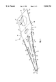
- FIG. 1 is an isometric view of a HGA load beam according to the present invention
- FIG. 2 is a top plan view of the load beam of FIG. 1;
- FIG. 3 is a side view of a head suspension assembly comprising the load beam of FIGS. 1 and 2;
- FIG. 4 is an enlarged cross-sectional view of the load beam of FIG. 1 taken along line 4--4;
- FIGS. 5A-5C are top plan views of alternative designs of the load beam of this invention.
- a load beam 10 comprises a square-shaped section base plate attachment segment 12 which extends to a bend region 14 and projects forward to a forward section 16.
- the load beam 10 is typically etched as a single piece from stainless steel sheet stock or another suitable material.
- FIG. 3 illustrates an HGA 33 incorporating the load beam 10.
- the bend region 14 provides the load beam 10 with the desirable spring force for preloading the HGA 33 and opposes the air bearing force generated by the floating action of the head or slider 36 over a rotating magnetic disk.
- the bend region 14 increases the in-plane or lateral, stiffness of the load beam 10, along the X-Y plane direction, in order to improve the dynamic performance of the HGA 33.
- the in-plane resonance frequency improves the HGA 33 positioning in high areal density disk drive applications.
- the bend region 14 includes a window 40 that assists in adjusting the out-of-plane (i.e., the Z direction which is normal to the lateral plane) spring force of the load beam 10, so that appropriate load may be applied to the slider 36 while flying over the rotating magnetic disk.
- the window 40 is shown to be rectangularly shaped, but it can assume any other polygon or arcuate shape. Alternatively, multiple windows may be distributed throughout the bend region 14. The window 40 may be eliminated partially or completely.
- the thickness of the bend region 14 may be reduced by etching it to a desired thickness, in order to obtain the desirable spring force for each specific application. In the present illustration the window 40 is symmetrically disposed relative to the load beam central axis B--B.
- Another feature of the bend region 14 is to shift the center of gravity of the load beam 10 from the forward edge 27 of the base plate attachment segment 12 to a distal tip 43 toward the rearward edge 25 along the central axis B--B.
- the rearward shift of the center of gravity will improve the overall shock performance of the HGA 33.
- the window 40 is sized and positioned in the bend region 14, so as to relocate the center of gravity to a more desirable rearward position, and further to provide an appropriate spring force to the load beam 10.
- the desired lateral stiffness of the load beam 10 is achieved by the novel shape and geometric configuration of the bend region 14.
- the bend region 14 has an expanded width relative to the base plate attachment segment 12, in order to increase the stiffness of the load beam 10 in the in-plane (X-Y plane) direction.
- the bend region is formed at an angle relative to the surface of the base plate attachment segment 12.
- the bend region 14 is defined by the forward edge 27 of the base plate attachment segment 12, two side edges 44, 46, and a forward edge 48 delineated by a hypothetical line SS.
- the side edges 44 and 46 are symmetrical relative to the central axis B--B of the load beam 10, and therefore only one side edge, i.e., side edge 44, will be described in detail.
- the side edge 44 is formed of two segments: a first segment QR and a second segment RS.
- the side edge 44 may alternatively include a different number of segments or shapes, provided it maintains an expanded width relative to the base plate attachment segment 12.
- the side edge 44 may be arcuately shaped.
- segment QR of side edge 44 is straight, and defines an angle "a" with the central axis B--B. Angle "a” may range between 3.5 degrees and 7 degrees; however, other values may alternatively be adapted.
- the length of segment QR may vary with the specific applications.
- Segment RS may be straight or have an arcuate shape.
- the position of points R, and the value of angle "a" may be adjusted in conjunction with the size, dimensions and position of the window 40, in order to optimize the static and dynamic performance of the HGA, and further to shift the center of gravity of the load beam 10 rearward, while minimizing its mass.
- the forward section 16 extends from the bend region 14, and from the forward edge 48 (dashed line S--S) to the narrower distal or forwardmost tip 43.
- the forward section 16 is formed with a tapered forward section plate 50; two side rails 52, 54; a central channel 55; tooling holes 58, 60; two sets of side openings 62, 64; and a dimple 66.
- An objective of the novel design is to increase the first torsion frequency mode and possibly the second torsion frequency mode by minimizing the mass of the forward section 16, while still maintaining a high stiffness to mass ratio.
- This objective is achieved in part, by providing the forward section 16 with two curved sections 70 and 72 that are symmetrical relative to the central axis B--B.
- Each curved section 70, 72 extends between two points S and T, with a curvature corresponding to that of the adjacent curved segment RS.
- the radius of curvature of each segment RT may vary between 0.35 inch and 0.65 inch.
- An exemplary curvature is 0.5 inch.
- the width of the distal end U--U is limited by the dimension of the dimple 66.
- the dimple 66 is approximately 15 mils (0.015 inch) in diameter.
- the length of the forward section 16 varies with respect to the total length of the load beam 10. A shorter forward section 16 can be employed, thereby further reducing the mass of the load beam 10. Such a design may require that the actuator arm (not shown), to which the boss 21 is swaged, be extended for a given disk drive design. A decided advantage in increased resonant frequencies is obtained with the present invention over prior art head suspension assemblies using load beams.
- the side rails 52, 54 are stiffening flanges that run substantially the length of the forward section 16.
- the side rails 52, 54 serve to stiffen the load beam 10 so that all bending in the out-of-plane direction is essentially at the bend regions with minimal deformation at the distal end U--U.
- the height of the side rails 52, 54 can be decreased, and still achieve equal or higher resonant frequencies than prior art devices.
- the height of such side rails or flanges would be 0.014 inch.
- the flange heights are made to be from 0.008-0.0095 inch (a 40-32 percent decrease in height).
- the central channel 55 helps to increase the overall stiffness of the load beam 10, and more particularly the stiffness in the out-of-plane or Z bending direction and in the torsion direction (turning motion around the major axis of the load beam 10). Another feature of the central channel 55 is to help in locating the center of gravity of the HGA 33 in proximity to or on the plane of the load beam 10, in order to reduce the excitation in the torsion modes of the load beam 10.
- the center of gravity of a conventional HGA is not necessarily located within the plane of the load beam, but is offset in the out-of-plane direction.
- An important feature of the present invention is that the center of gravity of the HGA 33 may be positioned within the plane of the load beam 10.
- the central channel 55 is formed of a single continuous straight trough that extends along the central or major axis B--B of the load beam 10.
- the central channel 55 may be located at any position along the major axis or central axis B--B, between the edge of the window 40 in the bend region 14 and the circular tooling hole 60.
- the channel 55 is located in the nodal area of the first torsion vibration mode of the load beam 10, which is an area of the load beam 10 that does not move much in the first torsion mode of vibration.
- the channel 55 tapers as it progresses toward the tooling hole 60.
- the width of the rearward end of the channel 55 may vary from 0.010 inch to 0.025 inch, with the forward end varying between 0.005 inch and 0.020 inch.
- the channel 55 is uniform along its entire axial length.
- the depth (in the out-of-plane direction of the load beam) may vary between 0.002 inch and 0.010 inch depending on the thickness of the material used to form the load beam 10.
- central channel 55 is shown to be formed of a single continuous trough, it should be clear that in an alternative embodiment the central channel 55 may be formed of a series of adjacent troughs. In yet another alternative, the central channel 55 is not a trough or a depression, but is rather embossed or raised. In still another embodiment, the central channel 55 may be formed of a combination of a series of adjacent or alternating troughs and raised sections. Some or all of these troughs and/or raised sections may be collinear with the major axis of the load beam 10, or alternatively, they may be offset relative thereto.
- the side openings 62, 64 are symmetrical relative to the central axis B--B of the load beam 10.
- the openings 62, 64 may have any desired shape even though they are illustrated in FIGS. 1 and 2 as being a square-shaped section.
- the openings 62, 64 are located outside the nodal area of the first torsion vibration mode of the load beam 10.
- a typical size of a single opening is approximately 0.010 inch by 0.010 inch. While seven openings 62, 64 are illustrated on each side of the forward section 16, it should be clear that a different number of openings may be alternatively selected.
- These side openings 62, 64 assist in reducing the overall mass of the HGA 33 and in positioning the center of gravity of the HGA 33 along the central axis of the load beam 10, closer to the base plate attachment segment 12.
- the reduction in the overall mass is beneficial to increase the frequencies of all vibration modes, and in particular the first torsion frequency, it being understood that the vibration frequencies are inversely proportional to mass and directly proportional to stiffness.
- the side openings 62, 64 are specifically located where the ratio of stiffness to mass is low for the vibration modes of interest, including the first torsion mode of load beam 10.
- Another advantage of having the center of gravity of the HGA 33 located as far rearward as possible is to render the HGA 33 more shock resistant, that is, to increase the amount of shock force required to separate the magnetic head from the disk, which improves disk drive performance.
- FIG. 5A depicts a plurality of windows 74A, 74B and 74C which are symmetrically disposed along the central longitudinal axis of the load beam.
- FIGS. 5B and 5C illustrate a tapered central channel 55A.
- FIG. 5C shows a pair of elongated rectangular windows 76A and 76B in the forward section of the load beam which may be used instead of the multiple windows 62 and 64.
- load beam which has low profile side rails, a low effective mass, and a low mass moment of inertia.
- the present design may be used to reduce disk spacing in disk drives.
Abstract
Description
Claims (15)
Priority Applications (2)
| Application Number | Priority Date | Filing Date | Title |
|---|---|---|---|
| US08/788,136 US5844752A (en) | 1997-01-24 | 1997-01-24 | Load beam head gimbal assembly with a bend region including a segment for shifting the center of gravity |
| US08/892,457 US5894381A (en) | 1997-01-24 | 1997-07-14 | Low mass sectioned load beam of head gimbal assembly having increased high first torsion frequency mode |
Applications Claiming Priority (1)
| Application Number | Priority Date | Filing Date | Title |
|---|---|---|---|
| US08/788,136 US5844752A (en) | 1997-01-24 | 1997-01-24 | Load beam head gimbal assembly with a bend region including a segment for shifting the center of gravity |
Related Child Applications (1)
| Application Number | Title | Priority Date | Filing Date |
|---|---|---|---|
| US08/892,457 Continuation-In-Part US5894381A (en) | 1997-01-24 | 1997-07-14 | Low mass sectioned load beam of head gimbal assembly having increased high first torsion frequency mode |
Publications (1)
| Publication Number | Publication Date |
|---|---|
| US5844752A true US5844752A (en) | 1998-12-01 |
Family
ID=25143550
Family Applications (1)
| Application Number | Title | Priority Date | Filing Date |
|---|---|---|---|
| US08/788,136 Expired - Lifetime US5844752A (en) | 1997-01-24 | 1997-01-24 | Load beam head gimbal assembly with a bend region including a segment for shifting the center of gravity |
Country Status (1)
| Country | Link |
|---|---|
| US (1) | US5844752A (en) |
Cited By (17)
| Publication number | Priority date | Publication date | Assignee | Title |
|---|---|---|---|---|
| US5946163A (en) * | 1995-06-07 | 1999-08-31 | Seagate Technology, Inc. | Actuator assembly flexible circuit with reduced stiffness |
| US6043956A (en) * | 1997-09-19 | 2000-03-28 | Nhk Spring Co., Ltd. | Suspension for disk drive |
| US6141187A (en) * | 1998-02-25 | 2000-10-31 | Manecomp Corp. | Suspension with reticulated spring portion and pattern etched beam portion |
| US6366430B1 (en) * | 1999-12-06 | 2002-04-02 | Seagate Technology Llc | Method and apparatus for improved static angle adjustment |
| US6388842B1 (en) | 1999-05-12 | 2002-05-14 | Seagate Technology Llc | Disc drive suspension bend section and method |
| US6532135B1 (en) * | 2000-06-06 | 2003-03-11 | Maxtor Corporation | Suspension load beam for disk drive actuator |
| US6633456B1 (en) * | 1998-10-29 | 2003-10-14 | International Business Machines Corporation | Suspension, head suspension assembly, and disk drive apparatus |
| US6636382B2 (en) * | 2000-12-27 | 2003-10-21 | Sae Magnetics (H.K.) Ltd. | Multilayer suspension, head gimbal assembly |
| US6751068B1 (en) | 2000-10-24 | 2004-06-15 | Seagate Technology Llc | Actuator assembly for a disc drive having shell extensions |
| US6833977B1 (en) * | 1998-01-22 | 2004-12-21 | Magnecomp Corporation | Load beam with enhanced resistance to plastic deformation in manufacturing processes |
| US20050201014A1 (en) * | 2004-03-10 | 2005-09-15 | Suncall Corporation | Magnetic head suspension |
| SG119159A1 (en) * | 2002-07-15 | 2006-02-28 | Univ Nanyang | Load beam and method for designing same |
| US7149057B2 (en) | 2000-07-11 | 2006-12-12 | Seagate Technology Llc | Open-channel torsion bend section |
| US7518829B1 (en) * | 2005-08-25 | 2009-04-14 | Hutchinson Technology Incorporated | Multi-radius rails for load beams on disk drive suspension assemblies |
| US7568277B1 (en) | 2006-11-02 | 2009-08-04 | Hutchinson Technology Incorporated | Method for manufacturing a multi-piece head suspension |
| US7774922B1 (en) | 2007-02-22 | 2010-08-17 | Hutchinson Technology Incorporated | Polyimide tabbing method for manufacturing disk drive head suspension components |
| US9153275B1 (en) * | 2014-10-15 | 2015-10-06 | HGST Netherlands B.V. | Laser-integrated head gimbal assembly having laser contact protection |
Citations (10)
| Publication number | Priority date | Publication date | Assignee | Title |
|---|---|---|---|---|
| JPS60226080A (en) * | 1984-04-25 | 1985-11-11 | Hitachi Ltd | Magnetic head supporting mechanism |
| JPS63148477A (en) * | 1986-12-11 | 1988-06-21 | Nec Corp | Support mechanism for magnetic head |
| EP0487914A2 (en) * | 1990-11-29 | 1992-06-03 | Hewlett-Packard Company | Stiffened load beam for a magnetic disk drive |
| US5126904A (en) * | 1989-12-07 | 1992-06-30 | Yutaka Sakurai | Magnetic head supporting structure with thick and thin portions for an information recording apparatus |
| US5408372A (en) * | 1990-09-07 | 1995-04-18 | Karam, Ii; Raymond M. | Transducer suspension damping via microstiffening |
| US5455727A (en) * | 1993-05-25 | 1995-10-03 | Maxtor Corporation | Transducer suspension assembly with a first pair of flanges for raising the resonant frequency and a second pair of flanges for increasing stiffness |
| USH1573H (en) * | 1993-07-01 | 1996-08-06 | Budde; Richard A. | Reduced mass/inertia suspension |
| US5719727A (en) * | 1993-01-07 | 1998-02-17 | Hutchinson Technology Incorporated | Interior stiffening and head lifter rails |
| US5739982A (en) * | 1996-08-23 | 1998-04-14 | International Business Machines Corporation | Laser treatment of head gimbal assembly components |
| US5777826A (en) * | 1995-03-31 | 1998-07-07 | International Business Machines Corporation | Load beam for supporting a transducer head in a disk drive |
-
1997
- 1997-01-24 US US08/788,136 patent/US5844752A/en not_active Expired - Lifetime
Patent Citations (10)
| Publication number | Priority date | Publication date | Assignee | Title |
|---|---|---|---|---|
| JPS60226080A (en) * | 1984-04-25 | 1985-11-11 | Hitachi Ltd | Magnetic head supporting mechanism |
| JPS63148477A (en) * | 1986-12-11 | 1988-06-21 | Nec Corp | Support mechanism for magnetic head |
| US5126904A (en) * | 1989-12-07 | 1992-06-30 | Yutaka Sakurai | Magnetic head supporting structure with thick and thin portions for an information recording apparatus |
| US5408372A (en) * | 1990-09-07 | 1995-04-18 | Karam, Ii; Raymond M. | Transducer suspension damping via microstiffening |
| EP0487914A2 (en) * | 1990-11-29 | 1992-06-03 | Hewlett-Packard Company | Stiffened load beam for a magnetic disk drive |
| US5719727A (en) * | 1993-01-07 | 1998-02-17 | Hutchinson Technology Incorporated | Interior stiffening and head lifter rails |
| US5455727A (en) * | 1993-05-25 | 1995-10-03 | Maxtor Corporation | Transducer suspension assembly with a first pair of flanges for raising the resonant frequency and a second pair of flanges for increasing stiffness |
| USH1573H (en) * | 1993-07-01 | 1996-08-06 | Budde; Richard A. | Reduced mass/inertia suspension |
| US5777826A (en) * | 1995-03-31 | 1998-07-07 | International Business Machines Corporation | Load beam for supporting a transducer head in a disk drive |
| US5739982A (en) * | 1996-08-23 | 1998-04-14 | International Business Machines Corporation | Laser treatment of head gimbal assembly components |
Cited By (22)
| Publication number | Priority date | Publication date | Assignee | Title |
|---|---|---|---|---|
| US5946163A (en) * | 1995-06-07 | 1999-08-31 | Seagate Technology, Inc. | Actuator assembly flexible circuit with reduced stiffness |
| US6043956A (en) * | 1997-09-19 | 2000-03-28 | Nhk Spring Co., Ltd. | Suspension for disk drive |
| US7265944B1 (en) | 1998-01-22 | 2007-09-04 | Magnecomp Corporation | Load beam spring portion with enhanced resistance to plastic deformation in manufacturing processes |
| US6833977B1 (en) * | 1998-01-22 | 2004-12-21 | Magnecomp Corporation | Load beam with enhanced resistance to plastic deformation in manufacturing processes |
| US6141187A (en) * | 1998-02-25 | 2000-10-31 | Manecomp Corp. | Suspension with reticulated spring portion and pattern etched beam portion |
| US6633456B1 (en) * | 1998-10-29 | 2003-10-14 | International Business Machines Corporation | Suspension, head suspension assembly, and disk drive apparatus |
| US6388842B1 (en) | 1999-05-12 | 2002-05-14 | Seagate Technology Llc | Disc drive suspension bend section and method |
| US6366430B1 (en) * | 1999-12-06 | 2002-04-02 | Seagate Technology Llc | Method and apparatus for improved static angle adjustment |
| US6650505B2 (en) * | 1999-12-06 | 2003-11-18 | Seagate Technology Llc | Method and apparatus for improved roll static angle adjustment |
| US6938326B1 (en) | 2000-06-06 | 2005-09-06 | Maxtor Corporation | Method of making at least one suspension load beam for an actuator assembly of a disk drive |
| US6532135B1 (en) * | 2000-06-06 | 2003-03-11 | Maxtor Corporation | Suspension load beam for disk drive actuator |
| US6687091B1 (en) | 2000-06-06 | 2004-02-03 | Maxtor Corporation | Suspension load beam for disk drive actuator with notch for reducing spring rate |
| US7149057B2 (en) | 2000-07-11 | 2006-12-12 | Seagate Technology Llc | Open-channel torsion bend section |
| US6751068B1 (en) | 2000-10-24 | 2004-06-15 | Seagate Technology Llc | Actuator assembly for a disc drive having shell extensions |
| US6636382B2 (en) * | 2000-12-27 | 2003-10-21 | Sae Magnetics (H.K.) Ltd. | Multilayer suspension, head gimbal assembly |
| SG119159A1 (en) * | 2002-07-15 | 2006-02-28 | Univ Nanyang | Load beam and method for designing same |
| US20050201014A1 (en) * | 2004-03-10 | 2005-09-15 | Suncall Corporation | Magnetic head suspension |
| US7365944B2 (en) | 2004-03-10 | 2008-04-29 | Suncall Corporation | Magnetic head suspension with reduced mass load beam portion |
| US7518829B1 (en) * | 2005-08-25 | 2009-04-14 | Hutchinson Technology Incorporated | Multi-radius rails for load beams on disk drive suspension assemblies |
| US7568277B1 (en) | 2006-11-02 | 2009-08-04 | Hutchinson Technology Incorporated | Method for manufacturing a multi-piece head suspension |
| US7774922B1 (en) | 2007-02-22 | 2010-08-17 | Hutchinson Technology Incorporated | Polyimide tabbing method for manufacturing disk drive head suspension components |
| US9153275B1 (en) * | 2014-10-15 | 2015-10-06 | HGST Netherlands B.V. | Laser-integrated head gimbal assembly having laser contact protection |
Similar Documents
| Publication | Publication Date | Title |
|---|---|---|
| US5894381A (en) | Low mass sectioned load beam of head gimbal assembly having increased high first torsion frequency mode | |
| US5844752A (en) | Load beam head gimbal assembly with a bend region including a segment for shifting the center of gravity | |
| US5894655A (en) | Monocoque head suspension and its method of construction | |
| EP0338698B1 (en) | A transducer head suspension assembly | |
| US5790347A (en) | Head suspension load beam and flexure construction for reducing structural height | |
| US8120878B1 (en) | Tubular stiffening rails for head suspension components | |
| US5923500A (en) | One-piece flexure for small magnetic heads | |
| EP0362072B1 (en) | A mechanism for suspending a head slider of a recording apparatus | |
| US11710503B1 (en) | Gimbal assembly geometry for hard disk drive | |
| US5850319A (en) | Head suspension for use with a dynamic storage drive having an optimized top profile defined by curved side edges | |
| EP0595513A2 (en) | Negative pressure air bearing slider | |
| US6191915B1 (en) | Suspension for disc drive that is capable of restraining excessive inclination of a head or occurrence of dimple separation when it is shocked, without enhancing the stiffness of a flexure | |
| US5027240A (en) | Disk head assembly load beam | |
| US6741424B1 (en) | Head suspension with rail and stiffener combination | |
| US20070115590A1 (en) | Disc flutter compensating suspension | |
| US5734525A (en) | Head suspension with torsion spring region | |
| US6219203B1 (en) | Microactuator integrated lead suspension for a high density hard disk drive | |
| US5568332A (en) | Magnetic head suspension | |
| JPH1196709A (en) | Suspension for disk device | |
| JP4269132B2 (en) | Disk drive suspension | |
| US6104572A (en) | Suspension having reduced torsional mode gain and sensitivity | |
| US5455727A (en) | Transducer suspension assembly with a first pair of flanges for raising the resonant frequency and a second pair of flanges for increasing stiffness | |
| US7430096B1 (en) | Head suspension with etched rail load beam | |
| US7518829B1 (en) | Multi-radius rails for load beams on disk drive suspension assemblies | |
| US7898771B2 (en) | Head suspension assembly having a high damping high stiffness component |
Legal Events
| Date | Code | Title | Description |
|---|---|---|---|
| AS | Assignment |
Owner name: READ-RITE CORPORATION, CALIFORNIA Free format text: ASSIGNMENT OF ASSIGNORS INTEREST;ASSIGNORS:BOZORGI, JAMSHID;ALLEN, A. MILLER;REEL/FRAME:008405/0182 Effective date: 19970115 |
|
| AS | Assignment |
Owner name: CANADIAN IMPERIAL BANK OF COMMERCE, NEW YORK Free format text: SECURITY AGREEMENT;ASSIGNOR:READ-RITE CORPORATION, A DELAWARE CORPORATION;REEL/FRAME:009528/0381 Effective date: 19980814 |
|
| STCF | Information on status: patent grant |
Free format text: PATENTED CASE |
|
| AS | Assignment |
Owner name: READ-RITE CORPORATION, CALIFORNIA Free format text: ASSIGNMENT AND RELEASE OF INTELLECTUAL PROPERTY SECURITY AGREEMENT;ASSIGNOR:CANADIAN IMPERIAL BANK OF COMMERCE, NEW YORK AGENCY, AS AGENT;REEL/FRAME:011680/0538 Effective date: 20010326 |
|
| FPAY | Fee payment |
Year of fee payment: 4 |
|
| AS | Assignment |
Owner name: TENNENBAUM CAPITAL PARTNERS, LLC, CALIFORNIA Free format text: SECURITY INTEREST;ASSIGNOR:READ-RITE CORPORATION;REEL/FRAME:013616/0399 Effective date: 20021224 |
|
| AS | Assignment |
Owner name: WESTERN DIGITAL (FREMONT), INC., CALIFORNIA Free format text: ASSIGNMENT OF ASSIGNORS INTEREST;ASSIGNOR:READ-RITE CORPORATION;REEL/FRAME:014506/0765 Effective date: 20030731 |
|
| AS | Assignment |
Owner name: READ-RITE CORPORATION, CALIFORNIA Free format text: RELEASE OF SECURITY INTEREST;ASSIGNOR:TENNENBAUM CAPITAL PARTNERS, LLC;REEL/FRAME:014499/0476 Effective date: 20030731 |
|
| AS | Assignment |
Owner name: GENERAL ELECTRIC CAPITAL CORPORATION, AS AGENT, CA Free format text: SECURITY INTEREST;ASSIGNORS:WESTERN DIGITAL TECHNOLOGIES, INC.;WESTERN DIGITAL (FREMONT), INC.;REEL/FRAME:014830/0957 Effective date: 20030919 |
|
| FPAY | Fee payment |
Year of fee payment: 8 |
|
| AS | Assignment |
Owner name: WESTERN DIGITAL TECHNOLOGIES, INC., CALIFORNIA Free format text: RELEASE BY SECURED PARTY;ASSIGNOR:GENERAL ELECTRIC CAPITAL CORPORATION, AS AGENT;REEL/FRAME:020599/0489 Effective date: 20070809 Owner name: WESTERN DIGITAL (FREMONT), INC., CALIFORNIA Free format text: RELEASE BY SECURED PARTY;ASSIGNOR:GENERAL ELECTRIC CAPITAL CORPORATION, AS AGENT;REEL/FRAME:020599/0489 Effective date: 20070809 |
|
| REMI | Maintenance fee reminder mailed | ||
| FPAY | Fee payment |
Year of fee payment: 12 |
|
| SULP | Surcharge for late payment |
Year of fee payment: 11 |
|
| AS | Assignment |
Owner name: WESTERN DIGITAL TECHNOLOGIES, INC., CALIFORNIA Free format text: ASSIGNMENT OF ASSIGNORS INTEREST;ASSIGNOR:WESTERN DIGITAL (FREMONT), LLC;REEL/FRAME:050450/0582 Effective date: 20190508 |