US5853192A - Variable vented housing - Google Patents
Variable vented housing Download PDFInfo
- Publication number
- US5853192A US5853192A US08/728,588 US72858896A US5853192A US 5853192 A US5853192 A US 5853192A US 72858896 A US72858896 A US 72858896A US 5853192 A US5853192 A US 5853192A
- Authority
- US
- United States
- Prior art keywords
- housing
- air bag
- inflation
- rate
- opening
- Prior art date
- Legal status (The legal status is an assumption and is not a legal conclusion. Google has not performed a legal analysis and makes no representation as to the accuracy of the status listed.)
- Expired - Fee Related
Links
Images


Classifications
-
- B—PERFORMING OPERATIONS; TRANSPORTING
- B60—VEHICLES IN GENERAL
- B60R—VEHICLES, VEHICLE FITTINGS, OR VEHICLE PARTS, NOT OTHERWISE PROVIDED FOR
- B60R21/00—Arrangements or fittings on vehicles for protecting or preventing injuries to occupants or pedestrians in case of accidents or other traffic risks
- B60R21/02—Occupant safety arrangements or fittings, e.g. crash pads
- B60R21/16—Inflatable occupant restraints or confinements designed to inflate upon impact or impending impact, e.g. air bags
- B60R21/26—Inflatable occupant restraints or confinements designed to inflate upon impact or impending impact, e.g. air bags characterised by the inflation fluid source or means to control inflation fluid flow
- B60R21/276—Inflatable occupant restraints or confinements designed to inflate upon impact or impending impact, e.g. air bags characterised by the inflation fluid source or means to control inflation fluid flow with means to vent the inflation fluid source, e.g. in case of overpressure
- B60R2021/2765—Inflatable occupant restraints or confinements designed to inflate upon impact or impending impact, e.g. air bags characterised by the inflation fluid source or means to control inflation fluid flow with means to vent the inflation fluid source, e.g. in case of overpressure comprising means to control the venting
Definitions
- the present invention generally relates to air bag inflator systems, modules, housings, inflators and air bags and more particularly to a housing which permits the rate of inflation and/or deflation of the air bag to be changed in accordance with an accident parameter independent of the type of inflator.
- Single stage inflators including both the conventional solid propellant inflator and hybrid inflator are capable of producing or providing inflation gas to inflate the air bag at a single inflation rate.
- U.S. Pat. No. 5,199,740 is illustrative of a single stage driver side hybrid inflator. It has long been recognized that air bag systems should have the capability of inflating the air bag at rates that correspond to certain accident parameters such as the severity of the crash, the size and weight of the occupant, whether the occupant is out of position, etc.
- U.S. Pat. No. 5,341,988 is illustrative of a hybrid inflator having a dual level output capability. The air bag inflation rate using this type of inflator can be tailored to the severity of the accident.
- inflators that provide a variable output inflation level can be used to their fullest potential to protect the occupant.
- the inflator comprises: a system for controlling the effective rate at which an air bag is filled comprising: a housing operatively communicated with the air bag such that as the air bag is pressurized by inflation gas such gas enters the housing increasing its internal pressure, the housing including: variable vent means for defining an opening through which a quantity of inflation gas is controllably diverted from the air bag to thereby reduce its rate of inflation from that rate which is achieved when the vent means is closed.
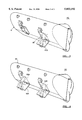
- FIG. 1 illustrates a projected view of a portion of the present invention.
- FIG. 2 illustrates a cross-sectional view of an air bag module incorporating the present invention.
- FIGS. 3 and 4 illustrate a housing with one or more vents.
- FIG. 5 illustrates an alternate embodiment of the present invention.
- FIGS. 6 and 7 illustrate a further embodiment of the invention.
- FIGS. 8 and 9 show an additional embodiment of the invention.
- FIGS. 1-4 show a variable vented air bag module 20 comprising a housing 22, air bag 24, deployment cover 26 and a source of inflation gas such as an air bag inflator 28.
- the deployment cover 26 includes a tear seam 30 which is torn open upon deployment of the air bag.
- the gas source 28 is secured in a conventional manner to the housing 22 such as by a plurality of threaded fasteners 32 and bolts 34. The fasteners are received through openings in the bottom 36 of the housing 22.
- Housing 22 includes opposing side walls 40 and end caps 42 defining a cavity 44 having an open mouth 46.
- the cover 26 is secured in a known manner proximate the open mouth 46.
- the gas source 28 is located within the cavity 44 and prior to the deployment of the air bag, the air bag is located within the housing in a compact, typically folded configuration.
- the air bag can be attached to the walls of the housing 22 or about the inflator. While not illustrated, certain installations involving a hybrid inflator utilize an intermediate member such as a hollow, cylindrically shaped manifold received about the gas source or inflator 28. In this case, the air bag 24 may be received about the manifold or as illustrated, secured to the housing 22.
- vents 50a, 50b Situated on one of the surfaces of the housing are a plurality of openings or vents 50a, 50b.
- these vents are formed as pre-formed openings within one of the sides 40 although they can be located on both sides and/or on the end caps 42.
- a means for selectively opening such vents Associated with each vent 50a,b is a means for selectively opening such vents, the purpose of which will be clear from the description below.
- Such means comprises doors 52a,b, hinged relative to the housing by corresponding hinges 54a and 54b.
- Each door 52a,b supports an actuator 60 to control when each door 52a,b opens.
- the actuator 60 comprises a solenoid responsive to a control signal communicated via wires 62 from an electronic control unit (ECU) 64.
- ECU electronice control unit
- Each solenoid includes a movable pin or plunger 66 received within a pin holder 68 secured to the housing.
- the pin holder comprises a bent metal or plastic element 70 having a ledge 72 of sufficient size to overlap the pin 66 in its unactuated position.
- the typical air bag inflator is designed to fill the air bag with inflation gas at a defined fill rate to a resulting internal pressure to protect a large male occupant during a 48 Kph (30 mph) frontal crash.
- the air bag may be forcibly expelled from the housing and filled at a rate that may be less than optimum to protect the smaller occupant, the occupant who is not properly seated, i.e. the out-of-position occupant, or operate optimally with regard to a child seated within a forward or rearward facing child seat. Consequently, it is desirable to be able to control the air bag inflation rate to accommodate the smaller sized occupant, the out-of-position occupant, etc.
- one solution is to provide an air bag inflator that is capable of inflating the air bag at a plurality of inflation rates responsive to some or each of these varied conditions. As can be appreciated, this adds to the complexity of the construction of the inflator 28.
- a sensor 74 is shown as providing input data to the ECU 64.
- the diagrammatically illustrated sensor 74 is to be interpreted as a plurality of sensors sufficient to define crash severity, such as an accelerometer or crash sensor, a sensor or sensors capable of determining whether the occupant is normally seated or out of position or whether or not a child seat is within the path of the inflating air bag, the sensor or sensors which can discriminate between the size and weight of an occupant.
- the ECU 64 operates upon the data received from the plurality of sensors 74 to determine if the rate at which the air bag is to be inflated is adequate to protect the occupants or if the rate should be lowered based upon one or more crash parameter.
- FIG. 2 As can be appreciated, upon activation of the gas source 28 a sufficient quantity of inflation gas is expelled from the gas source to inflate the air bag 24 within a determinable time period, i.e. the inflation rate, and to a determinable internal pressure. As the air bag inflates, the pressurized inflation gases fill the interior of the housing 40 elevating its pressure above ambient pressure. As can be appreciated, if a vent or bleed passage were provided within the housing a determinable quantity of inflation gas will be able to flow through these vents or bleed passages, thereby lessening the amount of inflation gas available to inflate the air bag, consequently the air bag would be inflated at a rate that is less than that which will occur without a vented housing.
- FIG. 3 which illustrates door 52b being opened with a determinable quantity of inflation gas 80 being purged from the housing. If it is desired to inflate the air bag at a rate less than that which would be achieved by opening one door, such as 52b, the other door 52a can be opened as illustrated in FIG. 4.
- FIG. 2 diagrammatically incorporates a spring 82 proximate the hinge location of the doors 52a,b.
- the spring 82 is configured so as to bias the doors outwardly. Upon activation of the actuators 60 the spring or springs 82 will rapidly open the doors irrespective of gravity or the internal pressure within the housing.
- the incorporation of the spring in conjunction with the doors permits the doors to be located on the top side or end caps 42 of the housing (in any orientation such as horizontal, vertical, oblique) in those situations where an enhanced opening rate of such doors is needed. While the above-illustrated embodiment of the invention has been shown with two discrete vents and movable doors, any number of vents and doors may be incorporated within the housing.
- the doors 52a and 52b described above can be operated separately or in tandem to control the effective inflation rate of the air bag.
- the air bag will become fully inflated typically within 30-70 milliseconds of the beginning of the crash. Subsequently, the occupant will begin to load the air bag, increasing its internal pressure as the occupant gradually moves further into the air bag. Consequently, once having determined the severity of the crash, the ECU 64 can generate a delayed signal, that is, a signal generated after the air bag has been inflated, to the actuator 60 for door 52a to open the previously unopened door 52a in a timed sequence to permit the bag to rapidly depressurize or deflate.
- FIG. 5 is a partial plan view showing a portion of one of the side walls 40.
- the opening 50a or 50b used to define a discrete vent is not used.
- the wall 40 is perforated by a series of thin, open sections such as would be achieved by laser cutting the side 40 of the housing 20'.
- the perimeter of these openings 90 defines the desired area of the vent opening.
- a plurality of thin discrete webs 92a is retained linking the side 40 with a movable flap or door portion 94 (that portion of the side 40 interior to openings 90).
- the various webs 92a keep the flap 94 dimensionally stable and in line with the remainder of the side 40.
- One or more of these webs is sufficiently long to define a robust hinge about which the flap 94 rotates.
- the total area of the webs 92a is chosen such that upon pressurization of the housing 40 to a predetermined level, these webs will break, permitting the flap 94 to rotate outwardly about those web portions 96a,b defining the hinge.
- the housing 20 of FIG. 5 may further include an electric actuator such as 60 mounted to the wall 40 having an actuating pin 66 which overlaps a portion of the flap 94 to provide a further degree of control in relation to the internal housing pressure at which the flap is opened.
- the various webs 92 would be designed to open at a low first pressure level.
- the actuator 60 activated, that is with the pin 66 withdrawn (in response to a signal from ECU 64) from interaction with the flap, the flap 94 will open when the internal pressure within the housing exceeds this first pressure level, thereby permitting inflation gas either during inflation of the air bag or during its depressurization to open.
- the pin 66 will prohibit the flap 94 from opening at the first pressure level.
- the opening of flap 94 can be delayed and then pushed open by the pressure internal to the housing.
- a pressure sensor diagrammatically shown as 98 can be installed within the housing and communicated to the ECU 64 such that the various actuators 60 can be energized in response to actual pressure measurements.
- FIG. 6 illustrates a side view of housing 20" having a side wall 40 with a plurality of discrete openings or vents 50a and 50b.
- the housing defines a track or groove generally shown as 100 in FIG. 7 which may be defined by two opposing, curved sections of wall 40 material.
- a slidable door 100a Situated within each track 100 (one for opening 50a and one for opening 50b) is a slidable door 100a (and 100b) moved by an actuator 60'. More particularly, the doors 100a,b are connected with actuator pins 66' of each actuator 60'.
- Each actuator 60' may be a single-step or multi-step solenoid.
- each actuator 60' may include a bias spring 106 which biases the door 100a,b to close. In the absence or termination of the control signal to the actuator 60' the door is moved to its closed position fully covering the vent opening 100a,b. In this manner, the amount of venting or purging of inflation gas during the inflation and subsequent depressurization of the air bag can be more finely controlled.
- FIG. 8 illustrates a partial view showing a portion of wall 40 of the housing 20.
- the wall includes at least one opening such as 50a enclosed by a flap or door 52a which is hinged at 54a.
- the housing and door include interlocking members 120 and 122.
- Member 120 includes a boss or protrusion 121 formed of the door material and positioned over an opening 124 within the door 52a.
- the protrusion 121 includes a plurality of opposed openings 126.
- the member 122 may also be formed as a protrusion or boss 130 of the side wall material or some other protruding object attached thereto.
- the boss 130 includes opposed openings 132a and b.
- a pyrotechnic wire cutting mechanism 140 such as Model No. 1SE192 manufactured by Eagle-Picher Inc., is positioned within a cavity formed within member 122.
- a lock wire 142 is threaded through openings 132a,b, 126a,b and through an opening 146 within the wire cutter 140.
- the lock wire 142 is severed, permitting member 120 to disengage from member 122 thereby permitting door 52a to rotate upon its hinge 54a in response to the pressure build-up within the housing 20.
- the control of the doors 52a,b can be controlled electrically using solenoids by electrical pyrotechnic wire cutters, cutting mechanisms, explosive bolts, or other means which operate sufficiently quickly (having a response time of approximately 30 milliseconds)
Abstract
Description
Claims (10)
Priority Applications (6)
| Application Number | Priority Date | Filing Date | Title |
|---|---|---|---|
| US08/728,588 US5853192A (en) | 1996-10-10 | 1996-10-10 | Variable vented housing |
| EP97943484A EP0930989B1 (en) | 1996-10-10 | 1997-09-19 | Variably vented air bag module |
| KR10-1999-7002993A KR100473013B1 (en) | 1996-10-10 | 1997-09-19 | Variably vented air bag modul |
| JP51754898A JP3606587B2 (en) | 1996-10-10 | 1997-09-19 | Airbag module with variable ventilation |
| PCT/US1997/016964 WO1998015434A1 (en) | 1996-10-10 | 1997-09-19 | Variably vented air bag modul |
| DE69712630T DE69712630T2 (en) | 1996-10-10 | 1997-09-19 | AIR BAG MODULE WITH ADJUSTABLE VENTILATION |
Applications Claiming Priority (1)
| Application Number | Priority Date | Filing Date | Title |
|---|---|---|---|
| US08/728,588 US5853192A (en) | 1996-10-10 | 1996-10-10 | Variable vented housing |
Publications (1)
| Publication Number | Publication Date |
|---|---|
| US5853192A true US5853192A (en) | 1998-12-29 |
Family
ID=24927463
Family Applications (1)
| Application Number | Title | Priority Date | Filing Date |
|---|---|---|---|
| US08/728,588 Expired - Fee Related US5853192A (en) | 1996-10-10 | 1996-10-10 | Variable vented housing |
Country Status (6)
| Country | Link |
|---|---|
| US (1) | US5853192A (en) |
| EP (1) | EP0930989B1 (en) |
| JP (1) | JP3606587B2 (en) |
| KR (1) | KR100473013B1 (en) |
| DE (1) | DE69712630T2 (en) |
| WO (1) | WO1998015434A1 (en) |
Cited By (49)
| Publication number | Priority date | Publication date | Assignee | Title |
|---|---|---|---|---|
| US6029932A (en) * | 1997-02-28 | 2000-02-29 | Daimlerchrysler Ag | Detonating valve for releasing openings of air bag landing systems |
| US6123358A (en) * | 1998-05-11 | 2000-09-26 | General Motors Corporation | Air bag module with variable inflation |
| US6131949A (en) * | 1999-06-09 | 2000-10-17 | The B. F. Goodrich Company | Venting systems for inflatables |
| WO2001003979A1 (en) * | 1999-07-12 | 2001-01-18 | Nippon Kayaku Kabushiki-Kaisha | Gas generator |
| US6241279B1 (en) * | 1998-05-26 | 2001-06-05 | Honda Giken Kogyo Kabushiki Kaisha | Air bag device |
| US6254125B1 (en) * | 1998-06-29 | 2001-07-03 | Peter Fassbaender | Method for operating a compressed-gas device in a motor vehicle |
| US6273463B1 (en) | 2000-04-19 | 2001-08-14 | Leslie D. Peterson | Airbag vent valve and system |
| US6290257B1 (en) * | 1998-07-27 | 2001-09-18 | Nihon Plast Co., Ltd. | Safety system for automobile |
| US6357791B1 (en) * | 2000-06-22 | 2002-03-19 | Trw Occupant Restraint Systems Gmbh & Co. Kg | Air bag module with vent |
| US6406055B1 (en) * | 2001-02-13 | 2002-06-18 | Trw Vehicle Safety Systems Inc. | Air bag module with vent |
| US6435549B1 (en) * | 1999-11-22 | 2002-08-20 | Honda Giken Kogyo Kabushiki Kaisha | Air bag device |
| US6439256B2 (en) * | 1999-12-04 | 2002-08-27 | Leica Camera Ag | Switchable flap valve |
| US6497431B1 (en) | 1997-07-09 | 2002-12-24 | Michael R. Schramm | Adaptive restraint system |
| US6517108B1 (en) | 2002-01-02 | 2003-02-11 | Ford Global Technologies, Inc. | Pyrotechnic air bag stitch vent |
| US6540257B2 (en) | 2001-04-10 | 2003-04-01 | Trw Inc. | Air bag module with vent |
| US6550807B1 (en) | 2000-11-21 | 2003-04-22 | Trw Vehicle Safety Systems Inc. | Air bag module with electronically modulated vent |
| US6588795B2 (en) * | 2001-01-10 | 2003-07-08 | Trw Vehicle Safety Systems Inc. | Air bag module with vent |
| US20030193177A1 (en) * | 2001-10-12 | 2003-10-16 | Trw Automotive U. S. Llc And | Air bag module with vent cover |
| US20030214125A1 (en) * | 2002-05-17 | 2003-11-20 | Schneider David W. | Active venting apparatus and method for airbag systems |
| US6669231B2 (en) * | 1998-11-04 | 2003-12-30 | Delphi Technologies, Inc. | Adaptive venting for an air bag module |
| US20040021307A1 (en) * | 2002-08-01 | 2004-02-05 | Ziolo Melissa S. | Airbag module using active venting membrane |
| EP1348615A3 (en) * | 2002-03-26 | 2004-03-17 | Honda Giken Kogyo Kabushiki Kaisha | On-vehicle airbag apparatus |
| US20040051286A1 (en) * | 2002-09-16 | 2004-03-18 | Trw Vehicle Safety Systems Inc. | Air bag module vent with releasable latch |
| US6736425B2 (en) | 2002-01-28 | 2004-05-18 | Ford Global Technologies, Llc | System for venting an air bag module |
| US6746045B2 (en) | 2002-04-05 | 2004-06-08 | Ford Global Technologies, Llc | Air bag inflator gas venting system |
| US20040113406A1 (en) * | 2001-10-12 | 2004-06-17 | Trw Automotive U.S. Llc | Air bag module with vent cover |
| US20040155443A1 (en) * | 2003-02-06 | 2004-08-12 | Brian Ford | Apparatus for actuating a flap for the venting of inflation gases |
| US6802528B2 (en) | 2002-04-05 | 2004-10-12 | Ford Global Technologies, Llc | Air bag cushion energy diverter |
| GB2400824A (en) * | 2003-04-23 | 2004-10-27 | Autoliv Dev | A vented air-bag |
| WO2004094201A1 (en) * | 2003-04-16 | 2004-11-04 | Key Safety Systems, Inc. | Airbag module with controlled venting of inflation gas |
| US6814372B1 (en) * | 1999-11-05 | 2004-11-09 | Ford Global Technologies, Llc | Method for apparatus for venting an inflatable restraint assembly |
| US20040232677A1 (en) * | 2002-09-16 | 2004-11-25 | Trw Vehicle Safety Systems Inc. | Air bag module with vent controlled by tether |
| US20050040634A1 (en) * | 2002-09-16 | 2005-02-24 | Trw Vehicle Safety Systems Inc. | Air bag module with locking member for locking the position of a vent member |
| US20050146122A1 (en) * | 2002-09-16 | 2005-07-07 | Trw Vehicle Safety Systems Inc. | Air bag module with locking member for locking the position of a vent member |
| US20050248137A1 (en) * | 2002-09-16 | 2005-11-10 | Trw Vehicle Safety Systems Inc. | Air bag module with vent controlled by tether |
| US20060033316A1 (en) * | 2004-08-13 | 2006-02-16 | Trw Automotive Safety Systems Gmbh | Gas bag module having discharge vent |
| US20060055159A1 (en) * | 2004-09-16 | 2006-03-16 | Trw Vehicle Safety Systems Inc. | Air bag module with actuatable vent part |
| US7017945B2 (en) | 2002-05-17 | 2006-03-28 | Depottey Timothy | Active venting apparatus and method for airbag systems |
| US20060071456A1 (en) * | 2004-09-24 | 2006-04-06 | Trw Vehicle Safety Systems, Inc. | Air bag module having a closure device for closing vents in response to full extension of the air bag |
| US20060071463A1 (en) * | 2004-10-01 | 2006-04-06 | Trw Automotive Safety Systems Gmbh | Gas bag module |
| US20060157962A1 (en) * | 2005-01-20 | 2006-07-20 | Trw Automotive Safety Systems Gmbh | Gas bag module for a vehicle occupant restraint system |
| US20070085312A1 (en) * | 2005-10-17 | 2007-04-19 | Takata Restraint Systems, Inc. | Airbag module with inflation control |
| US7341276B2 (en) | 2005-10-03 | 2008-03-11 | Key Safety Systems, Inc. | Airbag module with external venting |
| US20080116672A1 (en) * | 2006-11-20 | 2008-05-22 | Trw Vehicle Safety Systems Inc. | Air bag module with vent |
| US20080143087A1 (en) * | 2006-12-18 | 2008-06-19 | Toyoda Gosei Co., Ltd. | Airbag apparatus |
| US20080315567A1 (en) * | 2007-06-21 | 2008-12-25 | Trw Vehicle Safety Systems Inc. | Air bag with adaptive venting |
| US20090033081A1 (en) * | 2007-07-30 | 2009-02-05 | Trw Vehicle Safety Systems Inc. | Air bag with improved tear stitch |
| US20110140401A1 (en) * | 2007-06-21 | 2011-06-16 | Trw Vehicle Safety Systems Inc. | Tear stitching for inflatable vehicle occupant protection devices |
| US11498514B2 (en) * | 2017-07-26 | 2022-11-15 | Trw Airbag Systems Gmbh | Overigniting protection device, second ignition stage, gas generator and airbag module |
Families Citing this family (8)
| Publication number | Priority date | Publication date | Assignee | Title |
|---|---|---|---|---|
| US5899494A (en) * | 1997-09-18 | 1999-05-04 | Breed Automotive Technology, Inc. | Deflagration venting system for airbag systems |
| DE10107273B4 (en) * | 2001-02-16 | 2018-01-11 | Volkswagen Ag | Method for controlling a safety device for occupants of a vehicle and control unit |
| DE10157710B4 (en) * | 2001-11-24 | 2004-07-29 | Daimlerchrysler Ag | A method for controlling a ventilation device of a vehicle airbag and vehicle occupant safety system |
| KR100500287B1 (en) * | 2002-07-18 | 2005-07-11 | 현대모비스 주식회사 | Air-bag for a vehicle |
| US7083191B2 (en) | 2002-09-16 | 2006-08-01 | Trw Vehicle Safety Systems Inc. | Air bag module with vent controlled by tether |
| DE10352635B4 (en) * | 2003-11-11 | 2008-02-14 | GM Global Technology Operations, Inc., Detroit | airbag device |
| WO2005118355A1 (en) * | 2004-06-01 | 2005-12-15 | Autoliv Development Ab | Air bag internal pressure control method and air bag device |
| DE102008023131A1 (en) * | 2008-05-09 | 2009-11-12 | Volkswagen Ag | Pedal lever arrangement for passenger vehicle, has sliding part guided to fire wall or to bearing block for pedal lever, such that sliding part comes in contact with pressure rod during penetrating fire wall to split or release rod to bend |
Citations (7)
| Publication number | Priority date | Publication date | Assignee | Title |
|---|---|---|---|---|
| EP0357225A1 (en) * | 1988-07-29 | 1990-03-07 | Mazda Motor Corporation | Air bag system for automobile |
| US5184845A (en) * | 1988-05-20 | 1993-02-09 | Nissan Motor Co., Ltd. | Air-bag system |
| JPH0640305A (en) * | 1992-07-23 | 1994-02-15 | Toyota Motor Corp | Air bag pressure adjusting device |
| US5330226A (en) * | 1992-12-04 | 1994-07-19 | Trw Vehicle Safety Systems Inc. | Method and apparatus for detecting an out of position occupant |
| US5366242A (en) * | 1993-11-01 | 1994-11-22 | Trw Vehicle Safety Systems Inc. | Apparatus for controlling inflation of an air bag |
| US5388860A (en) * | 1991-10-10 | 1995-02-14 | Dynamit Nobel Aktiengesellschaft | Safety device for protecting the passenger of a motor vehicle from injury in a collision |
| US5524925A (en) * | 1995-08-25 | 1996-06-11 | Morton International, Inc. | Regulation of pressure in automotive airbags |
-
1996
- 1996-10-10 US US08/728,588 patent/US5853192A/en not_active Expired - Fee Related
-
1997
- 1997-09-19 WO PCT/US1997/016964 patent/WO1998015434A1/en active IP Right Grant
- 1997-09-19 JP JP51754898A patent/JP3606587B2/en not_active Expired - Fee Related
- 1997-09-19 EP EP97943484A patent/EP0930989B1/en not_active Expired - Lifetime
- 1997-09-19 KR KR10-1999-7002993A patent/KR100473013B1/en not_active IP Right Cessation
- 1997-09-19 DE DE69712630T patent/DE69712630T2/en not_active Expired - Fee Related
Patent Citations (7)
| Publication number | Priority date | Publication date | Assignee | Title |
|---|---|---|---|---|
| US5184845A (en) * | 1988-05-20 | 1993-02-09 | Nissan Motor Co., Ltd. | Air-bag system |
| EP0357225A1 (en) * | 1988-07-29 | 1990-03-07 | Mazda Motor Corporation | Air bag system for automobile |
| US5388860A (en) * | 1991-10-10 | 1995-02-14 | Dynamit Nobel Aktiengesellschaft | Safety device for protecting the passenger of a motor vehicle from injury in a collision |
| JPH0640305A (en) * | 1992-07-23 | 1994-02-15 | Toyota Motor Corp | Air bag pressure adjusting device |
| US5330226A (en) * | 1992-12-04 | 1994-07-19 | Trw Vehicle Safety Systems Inc. | Method and apparatus for detecting an out of position occupant |
| US5366242A (en) * | 1993-11-01 | 1994-11-22 | Trw Vehicle Safety Systems Inc. | Apparatus for controlling inflation of an air bag |
| US5524925A (en) * | 1995-08-25 | 1996-06-11 | Morton International, Inc. | Regulation of pressure in automotive airbags |
Cited By (80)
| Publication number | Priority date | Publication date | Assignee | Title |
|---|---|---|---|---|
| US6029932A (en) * | 1997-02-28 | 2000-02-29 | Daimlerchrysler Ag | Detonating valve for releasing openings of air bag landing systems |
| US6497431B1 (en) | 1997-07-09 | 2002-12-24 | Michael R. Schramm | Adaptive restraint system |
| US6431596B1 (en) * | 1998-05-11 | 2002-08-13 | Delphi Technologies, Inc. | Air bag module with variable inflation |
| US6123358A (en) * | 1998-05-11 | 2000-09-26 | General Motors Corporation | Air bag module with variable inflation |
| US6247726B1 (en) | 1998-05-11 | 2001-06-19 | Delphi Technologies, Inc. | Air bag module with variable inflation |
| US6241279B1 (en) * | 1998-05-26 | 2001-06-05 | Honda Giken Kogyo Kabushiki Kaisha | Air bag device |
| US6254125B1 (en) * | 1998-06-29 | 2001-07-03 | Peter Fassbaender | Method for operating a compressed-gas device in a motor vehicle |
| US6290257B1 (en) * | 1998-07-27 | 2001-09-18 | Nihon Plast Co., Ltd. | Safety system for automobile |
| US6669231B2 (en) * | 1998-11-04 | 2003-12-30 | Delphi Technologies, Inc. | Adaptive venting for an air bag module |
| US6131949A (en) * | 1999-06-09 | 2000-10-17 | The B. F. Goodrich Company | Venting systems for inflatables |
| WO2001003979A1 (en) * | 1999-07-12 | 2001-01-18 | Nippon Kayaku Kabushiki-Kaisha | Gas generator |
| US6814372B1 (en) * | 1999-11-05 | 2004-11-09 | Ford Global Technologies, Llc | Method for apparatus for venting an inflatable restraint assembly |
| US6435549B1 (en) * | 1999-11-22 | 2002-08-20 | Honda Giken Kogyo Kabushiki Kaisha | Air bag device |
| US6439256B2 (en) * | 1999-12-04 | 2002-08-27 | Leica Camera Ag | Switchable flap valve |
| US6273463B1 (en) | 2000-04-19 | 2001-08-14 | Leslie D. Peterson | Airbag vent valve and system |
| US6357791B1 (en) * | 2000-06-22 | 2002-03-19 | Trw Occupant Restraint Systems Gmbh & Co. Kg | Air bag module with vent |
| US6550807B1 (en) | 2000-11-21 | 2003-04-22 | Trw Vehicle Safety Systems Inc. | Air bag module with electronically modulated vent |
| US6588795B2 (en) * | 2001-01-10 | 2003-07-08 | Trw Vehicle Safety Systems Inc. | Air bag module with vent |
| US6406055B1 (en) * | 2001-02-13 | 2002-06-18 | Trw Vehicle Safety Systems Inc. | Air bag module with vent |
| US6540257B2 (en) | 2001-04-10 | 2003-04-01 | Trw Inc. | Air bag module with vent |
| US20040113406A1 (en) * | 2001-10-12 | 2004-06-17 | Trw Automotive U.S. Llc | Air bag module with vent cover |
| US20030193177A1 (en) * | 2001-10-12 | 2003-10-16 | Trw Automotive U. S. Llc And | Air bag module with vent cover |
| US6893041B2 (en) | 2001-10-12 | 2005-05-17 | Trw Automotive U.S. Llc | Air bag module with vent cover |
| US7108277B2 (en) | 2001-10-12 | 2006-09-19 | Trw Vehicle Safety Systems Inc. | Air bag module with vent cover |
| US6517108B1 (en) | 2002-01-02 | 2003-02-11 | Ford Global Technologies, Inc. | Pyrotechnic air bag stitch vent |
| US6736425B2 (en) | 2002-01-28 | 2004-05-18 | Ford Global Technologies, Llc | System for venting an air bag module |
| EP1348615A3 (en) * | 2002-03-26 | 2004-03-17 | Honda Giken Kogyo Kabushiki Kaisha | On-vehicle airbag apparatus |
| US7083187B2 (en) | 2002-03-26 | 2006-08-01 | Honda Giken Kogyo Kabushiki Kaisha | On-vehicle airbag apparatus |
| US6746045B2 (en) | 2002-04-05 | 2004-06-08 | Ford Global Technologies, Llc | Air bag inflator gas venting system |
| US20040188990A1 (en) * | 2002-04-05 | 2004-09-30 | Ford Global Technologies, Llc | Air bag inflator gas venting system |
| US6802528B2 (en) | 2002-04-05 | 2004-10-12 | Ford Global Technologies, Llc | Air bag cushion energy diverter |
| US6918613B2 (en) | 2002-04-05 | 2005-07-19 | Ford Global Technologies, Llc | Air bag inflator gas venting system |
| US20060208472A1 (en) * | 2002-05-17 | 2006-09-21 | Depottey Timothy A | Active venting apparatus and method for airbag systems |
| US7318602B2 (en) | 2002-05-17 | 2008-01-15 | Autoliv Asp, Inc. | Active venting apparatus and method for airbag systems |
| US7017945B2 (en) | 2002-05-17 | 2006-03-28 | Depottey Timothy | Active venting apparatus and method for airbag systems |
| US6971671B2 (en) | 2002-05-17 | 2005-12-06 | Autoliv Asp, Inc. | Active venting apparatus and method for airbag systems |
| US20030214125A1 (en) * | 2002-05-17 | 2003-11-20 | Schneider David W. | Active venting apparatus and method for airbag systems |
| US6752420B2 (en) * | 2002-08-01 | 2004-06-22 | Autoliv Asp, Inc. | Airbag module using active venting membrane |
| US20040021307A1 (en) * | 2002-08-01 | 2004-02-05 | Ziolo Melissa S. | Airbag module using active venting membrane |
| US20050040634A1 (en) * | 2002-09-16 | 2005-02-24 | Trw Vehicle Safety Systems Inc. | Air bag module with locking member for locking the position of a vent member |
| US7364192B2 (en) | 2002-09-16 | 2008-04-29 | Trw Vehicle Safety Systems Inc. | Air bag module with locking member for locking the position of a vent member |
| US20050146122A1 (en) * | 2002-09-16 | 2005-07-07 | Trw Vehicle Safety Systems Inc. | Air bag module with locking member for locking the position of a vent member |
| US20040051286A1 (en) * | 2002-09-16 | 2004-03-18 | Trw Vehicle Safety Systems Inc. | Air bag module vent with releasable latch |
| US6959945B2 (en) | 2002-09-16 | 2005-11-01 | Trw Vehicle Safety Systems Inc. | Air bag module with vent controlled by tether |
| US20050248137A1 (en) * | 2002-09-16 | 2005-11-10 | Trw Vehicle Safety Systems Inc. | Air bag module with vent controlled by tether |
| US20040232677A1 (en) * | 2002-09-16 | 2004-11-25 | Trw Vehicle Safety Systems Inc. | Air bag module with vent controlled by tether |
| US7275761B2 (en) | 2002-09-16 | 2007-10-02 | Trw Vehicle Safety Systems Inc. | Air bag module with locking member for locking the position of a vent member |
| US7083192B2 (en) | 2002-09-16 | 2006-08-01 | Trw Vehicle Safety Systems Inc. | Air bag module vent with releasable latch |
| WO2004045919A1 (en) * | 2002-11-18 | 2004-06-03 | Autoliv Asp, Inc. | Active venting apparatus and method for airbag systems |
| US20040155443A1 (en) * | 2003-02-06 | 2004-08-12 | Brian Ford | Apparatus for actuating a flap for the venting of inflation gases |
| US6830265B2 (en) | 2003-02-06 | 2004-12-14 | Key Safety Systems, Inc. | Apparatus for actuating a flap for the venting of inflation gases |
| WO2004094201A1 (en) * | 2003-04-16 | 2004-11-04 | Key Safety Systems, Inc. | Airbag module with controlled venting of inflation gas |
| CN1328092C (en) * | 2003-04-16 | 2007-07-25 | 关键安全体系股份有限公司 | Airbag module with controlled venting of inflation gas |
| US20040256839A1 (en) * | 2003-04-23 | 2004-12-23 | Leif Nilsson | Air-bag |
| GB2400824A (en) * | 2003-04-23 | 2004-10-27 | Autoliv Dev | A vented air-bag |
| GB2400824B (en) * | 2003-04-23 | 2006-02-01 | Autoliv Dev | Improvements in or relating to an air-bag |
| US7198292B2 (en) | 2003-04-23 | 2007-04-03 | Autoliv Development Ab | Air-bag |
| US20060033316A1 (en) * | 2004-08-13 | 2006-02-16 | Trw Automotive Safety Systems Gmbh | Gas bag module having discharge vent |
| US7334814B2 (en) | 2004-09-16 | 2008-02-26 | Trw Vehicle Safety Systems Inc. | Air bag module with actuatable vent part |
| US20060055159A1 (en) * | 2004-09-16 | 2006-03-16 | Trw Vehicle Safety Systems Inc. | Air bag module with actuatable vent part |
| US20060071456A1 (en) * | 2004-09-24 | 2006-04-06 | Trw Vehicle Safety Systems, Inc. | Air bag module having a closure device for closing vents in response to full extension of the air bag |
| US20060071463A1 (en) * | 2004-10-01 | 2006-04-06 | Trw Automotive Safety Systems Gmbh | Gas bag module |
| US7364193B2 (en) * | 2004-10-01 | 2008-04-29 | Trw Automotive Safety Systems Gmbh | Gas bag module |
| US20060157962A1 (en) * | 2005-01-20 | 2006-07-20 | Trw Automotive Safety Systems Gmbh | Gas bag module for a vehicle occupant restraint system |
| US7648165B2 (en) * | 2005-01-20 | 2010-01-19 | Trw Automotive Safety Systems Gmbh | Gas bag module for a vehicle occupant restraint system |
| US7341276B2 (en) | 2005-10-03 | 2008-03-11 | Key Safety Systems, Inc. | Airbag module with external venting |
| US7431336B2 (en) * | 2005-10-17 | 2008-10-07 | Tk Holdings Inc. | Airbag module with inflation control |
| US20070085312A1 (en) * | 2005-10-17 | 2007-04-19 | Takata Restraint Systems, Inc. | Airbag module with inflation control |
| US7798524B2 (en) | 2006-11-20 | 2010-09-21 | Trw Vehicle Safety Systems Inc. | Air bag module with vent |
| US20080116672A1 (en) * | 2006-11-20 | 2008-05-22 | Trw Vehicle Safety Systems Inc. | Air bag module with vent |
| US7552941B2 (en) * | 2006-12-18 | 2009-06-30 | Toyoda Gosei Co., Ltd. | Airbag apparatus |
| US20080143087A1 (en) * | 2006-12-18 | 2008-06-19 | Toyoda Gosei Co., Ltd. | Airbag apparatus |
| US20080315567A1 (en) * | 2007-06-21 | 2008-12-25 | Trw Vehicle Safety Systems Inc. | Air bag with adaptive venting |
| US7954850B2 (en) | 2007-06-21 | 2011-06-07 | Trw Vehicle Safety Systems Inc. | Air bag with adaptive venting |
| US20110140401A1 (en) * | 2007-06-21 | 2011-06-16 | Trw Vehicle Safety Systems Inc. | Tear stitching for inflatable vehicle occupant protection devices |
| US8544883B2 (en) | 2007-06-21 | 2013-10-01 | Trw Vehicle Safety Systems Inc. | Tear stitching for inflatable vehicle occupant protection devices |
| US20090033081A1 (en) * | 2007-07-30 | 2009-02-05 | Trw Vehicle Safety Systems Inc. | Air bag with improved tear stitch |
| US8262130B2 (en) | 2007-07-30 | 2012-09-11 | Trw Vehicle Safety Systems Inc. | Air bag with improved tear stitch |
| US8764058B2 (en) | 2007-07-30 | 2014-07-01 | Trw Vehicle Safety Systems Inc. | Air bag with improved tear stitch |
| US11498514B2 (en) * | 2017-07-26 | 2022-11-15 | Trw Airbag Systems Gmbh | Overigniting protection device, second ignition stage, gas generator and airbag module |
Also Published As
| Publication number | Publication date |
|---|---|
| JP2001504057A (en) | 2001-03-27 |
| DE69712630T2 (en) | 2002-12-05 |
| WO1998015434A1 (en) | 1998-04-16 |
| KR100473013B1 (en) | 2005-03-07 |
| DE69712630D1 (en) | 2002-06-20 |
| JP3606587B2 (en) | 2005-01-05 |
| EP0930989B1 (en) | 2002-05-15 |
| KR20000048951A (en) | 2000-07-25 |
| EP0930989A1 (en) | 1999-07-28 |
Similar Documents
| Publication | Publication Date | Title |
|---|---|---|
| US5853192A (en) | Variable vented housing | |
| US5695214A (en) | Air bag module with vent | |
| US6206408B1 (en) | Air bag module emergency venting system | |
| EP1506105B1 (en) | Active venting apparatus and method for airbag systems | |
| US6076854A (en) | Air bag assembly with selectively variable volume | |
| EP0405710B1 (en) | Inflatable restraint | |
| US5820162A (en) | Airbag system inflator | |
| US5709405A (en) | Variable mass flow airbag module | |
| US6517108B1 (en) | Pyrotechnic air bag stitch vent | |
| US20010038201A1 (en) | Adaptive venting for an air bag module | |
| US6550807B1 (en) | Air bag module with electronically modulated vent | |
| KR20070092316A (en) | Airbag module having a controllable tether | |
| GB2306409A (en) | Airbag vent valves opened by a command signal | |
| WO2000030901A1 (en) | Air bag module with variable inflation | |
| EP1590211A1 (en) | Airbag module for selectively venting airbag inflation gas | |
| WO2004045919A1 (en) | Active venting apparatus and method for airbag systems | |
| US6203061B1 (en) | Variable output air bag module with PAV heat sink | |
| EP1356998B1 (en) | Air bag module with vent | |
| EP1656283B1 (en) | A side air-bag system | |
| US20050156411A1 (en) | Method and apparatus for helping to protect an occupant of a vehicle | |
| US6752420B2 (en) | Airbag module using active venting membrane | |
| US5769452A (en) | Vehicle occupant protective air bag system | |
| JPH03284443A (en) | Energy absorption structure of vehicle body side | |
| US6487483B1 (en) | System and method of occupant sensing | |
| GB2316475A (en) | A gas generator arrangement for an airbag and a method of inflating an airbag |
Legal Events
| Date | Code | Title | Description |
|---|---|---|---|
| AS | Assignment |
Owner name: ALLIEDSIGNAL INC., NEW JERSEY Free format text: ASSIGNMENT OF ASSIGNORS INTEREST;ASSIGNORS:SIKORSKI, JEFFREY;RAINES, JASON;KELIER, GERALD;AND OTHERS;REEL/FRAME:008327/0503 Effective date: 19970116 |
|
| FEPP | Fee payment procedure |
Free format text: PAYOR NUMBER ASSIGNED (ORIGINAL EVENT CODE: ASPN); ENTITY STATUS OF PATENT OWNER: LARGE ENTITY |
|
| AS | Assignment |
Owner name: BREED AUTOMOTIVE TECHNOLOGY, INC., FLORIDA Free format text: ASSIGNMENT OF ASSIGNORS INTEREST;ASSIGNOR:ALLIEDSIGNAL INC.;REEL/FRAME:010113/0860 Effective date: 19990721 |
|
| AS | Assignment |
Owner name: CONGRESS FINANCIAL CORPORATION (FLORIDA), FLORIDA Free format text: SECURITY INTEREST;ASSIGNOR:BREED AUTOMOTIVE TECHNOLOGY, INC.;REEL/FRAME:011442/0646 Effective date: 20001226 |
|
| FPAY | Fee payment |
Year of fee payment: 4 |
|
| AS | Assignment |
Owner name: BREED AUTOMOTIVE TECHNOLOGY, INC., MICHIGAN Free format text: RELEASE OF SECURITY INTEREST IN TRADEMARKS;ASSIGNOR:CONGRESS FINANCIAL CORPORATION;REEL/FRAME:014313/0243 Effective date: 20030725 |
|
| AS | Assignment |
Owner name: CITICORP USA, INC., AS TERM C LOAN COLLATERAL AGEN Free format text: SECURITY AGREEMENT;ASSIGNOR:BREED AUTOMOTIVE TECHNOLOGY, INC.;REEL/FRAME:014428/0283 Effective date: 20030425 |
|
| AS | Assignment |
Owner name: KEY SAFETY SYSTEMS, INC., MICHIGAN Free format text: ASSIGNMENT OF ASSIGNORS INTEREST;ASSIGNOR:BREED AUTOMOTIVE TECHNOLOGY, INC.;REEL/FRAME:015017/0016 Effective date: 20040821 |
|
| FPAY | Fee payment |
Year of fee payment: 8 |
|
| AS | Assignment |
Owner name: CITICORP USA, INC., NEW YORK Free format text: SECURITY AGREEMENT;ASSIGNORS:KEY SAFETY SYSTEMS, INC;KSS HOLDINGS, INC;KSS ACQUISITION COMPANY;AND OTHERS;REEL/FRAME:019297/0249 Effective date: 20070308 Owner name: CITICORP USA, INC.,NEW YORK Free format text: SECURITY AGREEMENT;ASSIGNORS:KEY SAFETY SYSTEMS, INC;KSS HOLDINGS, INC;KSS ACQUISITION COMPANY;AND OTHERS;REEL/FRAME:019297/0249 Effective date: 20070308 |
|
| REMI | Maintenance fee reminder mailed | ||
| LAPS | Lapse for failure to pay maintenance fees | ||
| STCH | Information on status: patent discontinuation |
Free format text: PATENT EXPIRED DUE TO NONPAYMENT OF MAINTENANCE FEES UNDER 37 CFR 1.362 |