US5873815A - Access catheter and method for maintaining separation between a falloposcope and a tubal wall - Google Patents
Access catheter and method for maintaining separation between a falloposcope and a tubal wall Download PDFInfo
- Publication number
- US5873815A US5873815A US08/879,661 US87966197A US5873815A US 5873815 A US5873815 A US 5873815A US 87966197 A US87966197 A US 87966197A US 5873815 A US5873815 A US 5873815A
- Authority
- US
- United States
- Prior art keywords
- catheter
- lumen
- scope
- cage
- distal end
- Prior art date
- Legal status (The legal status is an assumption and is not a legal conclusion. Google has not performed a legal analysis and makes no representation as to the accuracy of the status listed.)
- Expired - Lifetime
Links
- 0 CCC1C(**)C(C2CCC3CCCCC4)C2=C3C4(C*)CC1 Chemical compound CCC1C(**)C(C2CCC3CCCCC4)C2=C3C4(C*)CC1 0.000 description 1
Images


Classifications
-
- A—HUMAN NECESSITIES
- A61—MEDICAL OR VETERINARY SCIENCE; HYGIENE
- A61B—DIAGNOSIS; SURGERY; IDENTIFICATION
- A61B1/00—Instruments for performing medical examinations of the interior of cavities or tubes of the body by visual or photographical inspection, e.g. endoscopes; Illuminating arrangements therefor
- A61B1/04—Instruments for performing medical examinations of the interior of cavities or tubes of the body by visual or photographical inspection, e.g. endoscopes; Illuminating arrangements therefor combined with photographic or television appliances
-
- A—HUMAN NECESSITIES
- A61—MEDICAL OR VETERINARY SCIENCE; HYGIENE
- A61B—DIAGNOSIS; SURGERY; IDENTIFICATION
- A61B1/00—Instruments for performing medical examinations of the interior of cavities or tubes of the body by visual or photographical inspection, e.g. endoscopes; Illuminating arrangements therefor
- A61B1/00064—Constructional details of the endoscope body
- A61B1/00071—Insertion part of the endoscope body
- A61B1/0008—Insertion part of the endoscope body characterised by distal tip features
- A61B1/00082—Balloons
-
- A—HUMAN NECESSITIES
- A61—MEDICAL OR VETERINARY SCIENCE; HYGIENE
- A61B—DIAGNOSIS; SURGERY; IDENTIFICATION
- A61B1/00—Instruments for performing medical examinations of the interior of cavities or tubes of the body by visual or photographical inspection, e.g. endoscopes; Illuminating arrangements therefor
- A61B1/00064—Constructional details of the endoscope body
- A61B1/00071—Insertion part of the endoscope body
- A61B1/0008—Insertion part of the endoscope body characterised by distal tip features
- A61B1/00085—Baskets
-
- A—HUMAN NECESSITIES
- A61—MEDICAL OR VETERINARY SCIENCE; HYGIENE
- A61B—DIAGNOSIS; SURGERY; IDENTIFICATION
- A61B1/00—Instruments for performing medical examinations of the interior of cavities or tubes of the body by visual or photographical inspection, e.g. endoscopes; Illuminating arrangements therefor
- A61B1/00131—Accessories for endoscopes
- A61B1/00135—Oversleeves mounted on the endoscope prior to insertion
-
- A—HUMAN NECESSITIES
- A61—MEDICAL OR VETERINARY SCIENCE; HYGIENE
- A61B—DIAGNOSIS; SURGERY; IDENTIFICATION
- A61B1/00—Instruments for performing medical examinations of the interior of cavities or tubes of the body by visual or photographical inspection, e.g. endoscopes; Illuminating arrangements therefor
- A61B1/00147—Holding or positioning arrangements
- A61B1/00149—Holding or positioning arrangements using articulated arms
-
- A—HUMAN NECESSITIES
- A61—MEDICAL OR VETERINARY SCIENCE; HYGIENE
- A61B—DIAGNOSIS; SURGERY; IDENTIFICATION
- A61B1/00—Instruments for performing medical examinations of the interior of cavities or tubes of the body by visual or photographical inspection, e.g. endoscopes; Illuminating arrangements therefor
- A61B1/005—Flexible endoscopes
- A61B1/01—Guiding arrangements therefore
-
- A—HUMAN NECESSITIES
- A61—MEDICAL OR VETERINARY SCIENCE; HYGIENE
- A61B—DIAGNOSIS; SURGERY; IDENTIFICATION
- A61B1/00—Instruments for performing medical examinations of the interior of cavities or tubes of the body by visual or photographical inspection, e.g. endoscopes; Illuminating arrangements therefor
- A61B1/303—Instruments for performing medical examinations of the interior of cavities or tubes of the body by visual or photographical inspection, e.g. endoscopes; Illuminating arrangements therefor for the vagina, i.e. vaginoscopes
-
- A—HUMAN NECESSITIES
- A61—MEDICAL OR VETERINARY SCIENCE; HYGIENE
- A61B—DIAGNOSIS; SURGERY; IDENTIFICATION
- A61B1/00—Instruments for performing medical examinations of the interior of cavities or tubes of the body by visual or photographical inspection, e.g. endoscopes; Illuminating arrangements therefor
- A61B1/32—Devices for opening or enlarging the visual field, e.g. of a tube of the body
-
- A—HUMAN NECESSITIES
- A61—MEDICAL OR VETERINARY SCIENCE; HYGIENE
- A61B—DIAGNOSIS; SURGERY; IDENTIFICATION
- A61B5/00—Measuring for diagnostic purposes; Identification of persons
- A61B5/68—Arrangements of detecting, measuring or recording means, e.g. sensors, in relation to patient
- A61B5/6846—Arrangements of detecting, measuring or recording means, e.g. sensors, in relation to patient specially adapted to be brought in contact with an internal body part, i.e. invasive
- A61B5/6886—Monitoring or controlling distance between sensor and tissue
-
- A—HUMAN NECESSITIES
- A61—MEDICAL OR VETERINARY SCIENCE; HYGIENE
- A61B—DIAGNOSIS; SURGERY; IDENTIFICATION
- A61B90/00—Instruments, implements or accessories specially adapted for surgery or diagnosis and not covered by any of the groups A61B1/00 - A61B50/00, e.g. for luxation treatment or for protecting wound edges
- A61B90/50—Supports for surgical instruments, e.g. articulated arms
-
- A—HUMAN NECESSITIES
- A61—MEDICAL OR VETERINARY SCIENCE; HYGIENE
- A61B—DIAGNOSIS; SURGERY; IDENTIFICATION
- A61B1/00—Instruments for performing medical examinations of the interior of cavities or tubes of the body by visual or photographical inspection, e.g. endoscopes; Illuminating arrangements therefor
- A61B1/00163—Optical arrangements
- A61B1/00165—Optical arrangements with light-conductive means, e.g. fibre optics
-
- A—HUMAN NECESSITIES
- A61—MEDICAL OR VETERINARY SCIENCE; HYGIENE
- A61B—DIAGNOSIS; SURGERY; IDENTIFICATION
- A61B1/00—Instruments for performing medical examinations of the interior of cavities or tubes of the body by visual or photographical inspection, e.g. endoscopes; Illuminating arrangements therefor
- A61B1/06—Instruments for performing medical examinations of the interior of cavities or tubes of the body by visual or photographical inspection, e.g. endoscopes; Illuminating arrangements therefor with illuminating arrangements
- A61B1/07—Instruments for performing medical examinations of the interior of cavities or tubes of the body by visual or photographical inspection, e.g. endoscopes; Illuminating arrangements therefor with illuminating arrangements using light-conductive means, e.g. optical fibres
-
- A—HUMAN NECESSITIES
- A61—MEDICAL OR VETERINARY SCIENCE; HYGIENE
- A61B—DIAGNOSIS; SURGERY; IDENTIFICATION
- A61B17/00—Surgical instruments, devices or methods, e.g. tourniquets
- A61B17/22—Implements for squeezing-off ulcers or the like on the inside of inner organs of the body; Implements for scraping-out cavities of body organs, e.g. bones; Calculus removers; Calculus smashing apparatus; Apparatus for removing obstructions in blood vessels, not otherwise provided for
- A61B17/221—Gripping devices in the form of loops or baskets for gripping calculi or similar types of obstructions
- A61B2017/2215—Gripping devices in the form of loops or baskets for gripping calculi or similar types of obstructions having an open distal end
-
- A—HUMAN NECESSITIES
- A61—MEDICAL OR VETERINARY SCIENCE; HYGIENE
- A61B—DIAGNOSIS; SURGERY; IDENTIFICATION
- A61B90/00—Instruments, implements or accessories specially adapted for surgery or diagnosis and not covered by any of the groups A61B1/00 - A61B50/00, e.g. for luxation treatment or for protecting wound edges
- A61B90/08—Accessories or related features not otherwise provided for
- A61B2090/0815—Implantable devices for insertion in between organs or other soft tissues
Definitions
- the present invention relates generally to endoscopic surgical methods and apparatus. More particularly, the present invention provides an access catheter having a distally protruding structure which maintains separation between a viewing scope and a lumenal wall.
- Falloposcopic access and imaging techniques are generally performed as follows.
- a hysteroscope is positioned within the uterus and an irrigating solution is introduced to distend the uterus and permit video monitoring.
- a very small guidewire is then introduced through the hysteroscope and advanced past the ostium and into the fallopian tube. The guidewire will continue to be advanced until it approaches the distal fimbria.
- a small tubular access catheter may then be advanced through the hysteroscope and over the guidewire into the fallopian tube, again preferably approaching the distal fimbria.
- the falloposcope (which is a small diameter fiberoptic bundling including both imaging and illumination fibers in a single shaft) is advanced until its distal end reaches the distal end of the access catheter. Imaging may then be performed in a retrograde manner with the falloposcope and access catheter being drawn outwardly together through the fallopian tube while producing an image on the associated video monitor.
- the lumen of the tubular access catheter will also provide an access path for devices, such as drug delivery catheters, small instruments, and the like, for treatment of tubal lumen disease.
- U.S. Pat. No. 4,793,326 describes an industrial endoscope having an elongated arm member to facilitate advancing separate illumination and observation windows past the abrupt steps of piping elbow joints.
- U.S. Pat. No. 4,717,387 describes an intercardiac catheter having a distal balloon for positioning the catheter with respect to a body surface to be viewed through an optical scope.
- U.S. Pat. No. 5,263,982 describes an endoscopic catheter having a laterally offset movable guidewire.
- U.S. Pat. Nos. 5,047,848 and 4,825,259 disclose baroscope having specialized distal tip gauges which permit optical measurements of imaged features.
- U.S. Pat. No. 4,608,965 discloses an endoscopic sheath having a Malecott-type structure for anchoring the scope in a body cavity.
- U.S. Pat. No. 5,358,496 is representative of numerous instruments intended to be inserted through endoscopes.
- U.S. Pat. Nos. 3,866,601; 4,306,566; 4,350,147; 4,846,812; 5,099,827; 5,263,928; 5,279,596; 5,306,261; 5,307,814; 5,308,342; 5,385,152; are also relevant.
- the present invention provides a method for viewing a lumenal wall of a narrow body lumen.
- the method of the present invention comprises introducing a catheter within a body lumen and positioning an optical viewing scope within a lumen of the catheter so that a distal end of the scope is at a scope viewing position adjacent to a distal end of the catheter.
- a spacing structure is positioned between the lumenal wall and the distal end of the scope maintains separation between the lumen wall and the scope.
- the lumenal wall is imaged through the scope while the spacing structure maintains separation between the distal end of the scope and the lumenal wall. This separation helps prevent imaging white-out conditions which might otherwise occur when the optical viewing scope and body lumen wall are in close proximity.
- the catheter is advanced distally of a target region of the body lumen during the introducing step, and the catheter and scope are proximally withdrawn while imaging through the distally oriented scope. This is generally referred to as "retrograde imaging.”
- the imaging step comprises viewing the lumen wall at least in part through a cage disposed over the distal end of the scope.
- the spacing structure may comprise a guidewire which extends distally from the catheter, which guidewire may also be rotated during introduction of the catheter to maneuver the catheter through a body lumen system.
- the spacing structure may comprise a wire loop extending distally from the catheter body. Such a wire loop may be expanded by advancing a proximal length of the wire relative to the proximal end of the catheter. In this way, the size of the loop can be adjusted maintain separation between the body lumen wall and the optical viewing position.
- the present invention provides an improved method for viewing a target region of a fallopian tube.
- the method is of the type including transcervically accessing the fallopian tube with the catheter and inserting an optical viewing scope within a lumen of the catheter so that distal ends of the scope and catheter are adjacent to each other, and then retrograde imaging the fallopian tube by withdrawing the scope and catheter together.
- the improvement comprises promoting axial alignment between the tubal wall and the distal end of the scope with a structure extending distally from the distal end of the catheter.
- Axial alignment between the distal end of the scope and the tubal wall will optionally comprise axially rotating the catheter to engage the structure against the tubal wall, where the structure is unsymmetrical about an axis of the catheter lumen.
- such an unsymmetrical spacing structure can be used to selectively engage only that portion of the tubal wall which is necessary to avoid a white-out.
- the unsymmetrical spacing structure further avoids blocking of the imaging view where not required to prevent intrusion of the tubal wall toward the viewing scope.
- the present invention provides a catheter for viewing a wall of a narrow body lumen, the catheter for use in combination with an optical viewing scope of the type including both illumination fibers and viewing fibers.
- the catheter comprises an elongate tubular body having a proximal end, a distal end and a central lumen therebetween.
- the lumen slidably receives the shaft of the scope to a scope viewing position adjacent to the distal end of the body.
- a spacing structure extends distally from the distal end, usually being fixed or coupled thereto, so as to separate the scope viewing position from the lumen wall.
- the catheter of the present invention need only include a single axial lumen, thereby minimizing its cross-sectional size.
- the spacing structure is affixed with a coupler ring which fittingly engages the body, the coupler ring ideally being disposed within the body lumen and having an outer diameter which is larger than a relaxed lumen diameter.
- the spacing structure comprises a cage disposed over the scope viewing position.
- the cage may comprise a distal extension of the body having a plurality of viewing slots, or may alternatively comprise a separate structure attached to the distal end of the catheter.
- the spacing structure comprises a guidewire which extends distally of the body, typically being cantilevered from the distal end of the catheter at the edge of a distal lumen opening.
- the guidewire comprises a coiled distal section and an uncoiled section between the catheter and coil. This provides an increasing distal flexibility comparable to that of distally tapering guidewires, but with a decrease in proximal guidewire cross-section.
- the flexibility of the guidewire is ideally similar to tapered guidewires sold under the tradenames "Traveler” and "Robust” by Conceptus, Inc. of San Carlos, Calif., the present assignee.
- the guidewire may thus find use in maneuvering the catheter through the body lumen, and may also allow the catheter to be advanced while "antigrade" imaging through a scope at the scope viewing position.
- antigrade imaging will potentially provide a means for directing the catheter distally, and also provide a simultaneous image of the tubal wall.
- the spacing structure may comprise an expandable distal loop actuable by advancing a proximal portion or extension of the loop relative to the proximal end of the body. This provides a controllable separation between the lumen wall and the scope viewing position to overcome white-out conditions as they are encountered along the body lumen.
- the spacing structure comprises one or more diagonal tips extending from the distal end of the body.
- the present invention provides a method for viewing a luminal wall of a narrow body lumen, the method comprising introducing a catheter into the body lumen, the catheter having an access lumen and a distal spacing structure.
- An optical viewing scope is positioned through the access lumen of the catheter.
- the scope images the luminal wall through the spacing structure while the spacing structure maintains separation between the distal end of the scope and the luminal wall.
- imaging is performed through openings defined by discreet structural elements of the spacing structure, the spacing structure typically comprising a perforate cage.
- the cage flexes to accommodate bends in the body lumen, and includes a large, rounded, distally oriented surface that promotes tracking of the cage and access catheter along the body lumen when the catheter advances axially therein.
- the cage optionally helps to center the scope within the body lumen, and may also distend the body lumen to facilitate viewing of the inner surface of the luminal wall.
- such a caged structure will allow safe and effective antigrade imaging of narrow body lumens (such as the fallopian tube) by carefully controlling the relative positions of the scope and portion of the surrounding luminal wall.
- the present invention provides a catheter for viewing a wall of a narrow body lumen.
- the catheter of the present invention will be used in combination with an optical viewing scope, the catheter comprising an elongated tubular body having a proximal end, a distal end, and a lumen therebetween.
- a spacing structure with a plurality of cage elements extends distally from the distal end of the tubular body, the spacing structure adapted to maintain separation between the scope and the surrounding luminal wall when the scope images the body lumen between the cage elements.
- the spacing structure is adapted to track along the body lumen when axially advanced therein, typically having at least an axial portion which is flexible, and a tracking tip which provides a large, rounded distally oriented surface.
- the axial elements comprise a super-elastic shape memory alloy such as NitinolTM.
- the present invention provides a fallopian tube viewing system for imaging a tubal wall of the fallopian tube, the viewing system comprising a falloposcope having a proximal end, a distal end, and an axis therebetween.
- the access catheter has an elongate tubular body with a proximal end, a distal end, a lumen therebetween which slidably receives the falloposcope.
- a flexible separation structure extends distally from the distal end of the body to maintain separation between the scope and the surrounding tubal wall when the scope is disposed within the lumen of the access catheter, when the scope and catheter are disposed within the fallopian tube, and when the body lumen is imaged through the scope through the separation structure.
- the present invention provides a method for manufacturing a caged access catheter, the method comprising attaching a plurality of flexible elongate cage elements to each other at a junction.
- a tracking tip is formed at the junction, the tracking tip having a rounded surface which is larger than the combined cross-sections of the cage elements.
- the cage elements are affixed about a lumen of a tubular body so that the elongate elements extend distally from the tubular body.
- FIG. 1 illustrates a prior art access catheter and optical viewing scope used for retrograde imaging of a fallopian tube.
- FIG. 2 is a detail view showing the distal ends of the access catheter and optical viewing scope of FIG. 1 in close proximity to the tubal wall, which is typical of the white-out conditions encountered when using the access catheters of the prior art.
- FIG. 3 illustrates a preferred combination of a hysteroscope, access catheter, and falloposcope for use in imaging a fallopian tube, according to the principles of the present invention.
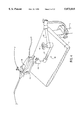
- FIG. 4 illustrates a preferred method for supporting the proximal end of the hysteroscope according to the method of the present invention, wherein the proximal end is immobilized by a support structure attached to a table.
- FIG. 5 illustrates a falloposcope which is separated from a tubal wall by an access catheter having a distal cage structure, according to the principles of the present invention.
- FIG. 6 illustrates an alternative cage structure formed by cutting axial viewing slots in a distal extension of the catheter body.
- FIG. 7 illustrates a falloposcope which is separated from a fallopian tube wall by an access catheter having a distally protruding diagonal tip, in accordance with the principles of the present invention.
- FIG. 8 illustrates an access catheter having a plurality of diagonal tips extending from the distal end of the catheter body, in accordance with the principles of the present invention.
- FIGS. 9A and B illustrate an access catheter having a plurality of side openings and a central lumen opening which provide a balanced flow path for irrigation fluid to maintain separation between the falloposcope and the tubal wall.
- FIGS. 10A, B and C illustrate a preferred access catheter having a distal guidewire for maintaining axial alignment and separation between a falloposcope and a surrounding fallopian tube.
- FIGS. 11A, B, C, and D illustrate access catheters having a guidewire which extends from the distal end of the catheter body to form a distal loop, which distal loop can be expanded by axially advancing a proximal extension of the guidewire, in accordance with the principles of the present invention.
- FIGS. 12A and B illustrate an access catheter having an extended diagonal tip formed by joining different tubes and cutting the joined tubes along a curve.
- FIGS. 13-13D illustrate a preferred embodiment of a caged access catheter having flexible cage elements and a tracking tip with a rounded distal surface to improve trackability, particularly during antigrade imaging of tortuous narrow body lumens such as the fallopian tubes.
- FIGS. 14A-H illustrate a variety of alternative flexible caged access catheters according to the principles of the present invention.
- FIGS. 15A and B illustrate alternative methods for securely attaching a tracking tip body having a rounded surface at the distal end of a flexible cage by winding subcoils over the cage elements, and then soldering an outer coil over the distal end so that the solder forms the distal rounded surface.
- FIG. 16 illustrates an alternative tracking tip formed by melting the distal ends of the flexible cage elements using thermocouple forming techniques.
- FIG. 17 illustrates an alternative distal cage having a proximal collar to facilitate attachment of the cage to the catheter body.
- FIGS. 18A and B illustrate methods for producing a caged access catheter in which the cage elements are joined to each other prior to attachment to the catheter body, either before or after the caged elements are bent to their final shape.
- FIG. 19A illustrates an alternative access catheter according to the present invention in which a toroidal balloon disposed at the distal end of the catheter maintains separation between the luminal wall and the distal end of the scope.
- FIG. 19B illustrates an alternative catheter according to the principles of the present invention in which an optically transparent balloon maintains separation between the scope and the luminal wall while the luminal wall is imaged through the balloon membrane.
- FIGS. 20-22A illustrate the enhanced trackability provided by the distal rounded surface and the axially flexible cage of the preferred access catheter of FIG. 13.
- FIG. 23 illustrates a flexible access catheter similar to the preferred access catheter of FIG. 13 in which the cage is bent to function as a steerable guidewire, and also illustrates axial manipulation of the scope within the cage to provide enhanced imaging flexibility, according to the principles of the present invention.
- the present invention provides systems, devices, and methods for accessing and imaging narrow body lumens for the diagnosis and treatment of lumenal disease.
- the techniques and apparatus of the present invention will generally make use of small optical viewing scopes having both imaging and illumination capabilities, and will maintain separation between the scopes and the lumenal wall to enhance image quality and reliability.
- the structures and methods will also help align the lumenal wall relative to the scope for effective viewing.
- the present invention will have applications for imaging of the vasculature (particularly of the coronary arteries), the ureter, and spinal column.
- the most immediate application of the present invention will be in trancervical imaging and accessing of the fallopian tubes.
- the methods and devices of the present invention can promote effective antigrade imaging of these narrow, delicate, tortuous body lumens, allowing positioning to be optically directed, and avoiding the time consuming guidewire positioning and replacement steps of known retrograde tubal access methods.
- a prior art retrograde fallopian tube viewing system 10 includes an access catheter 12 and a falloposcope 14.
- Prior art viewing system 10 is inserted to the distal portion of a fallopian tube 16, and is withdrawn proximally as indicated to provide retrograde imaging.
- Fallopian tube 16 is quite narrow and tortuous, and the tubal wall is highly flexible.
- the tubal wall is distended by the access cover 12, and then collapses down to its relaxed shape after a distal end 18 of the access catheter has passed.
- the tubal wall often comes into close proximity with distal end of falloposcope 20.
- Falloposcope 14 generally includes two distinct types of optical fibers.
- the first group of optical fibers is used to transmit light to the distal end of falloposcope 20 to provide illumination for optical viewing.
- the second type of optical fiber often comprising a single optical fiber bundle called a "coherent image fiber optic bundle," transmits an optical image from a lens at a distal end of falloposcope 20 to a proximal imaging apparatus.
- the image itself comprises the illumination light from the illumination fibers which is reflected by objects located within a field of view 22 of distal end of falloposcope 20.
- the imaging apparatus is unable to produce a coherent picture, and a partial or a total white-out occurs on the viewing monitor.
- a preferred method for performing falloposcopic procedures makes use of a hysteroscopic viewing scope 30 having a working shaft 32 with a deflectable distal end 34, as shown in FIGS. 3 and 4.
- Working shaft 32 is introduced to the uterus U, ideally using an adjustable support system 40.
- Deflectable distal end 34 is directed toward an ostium 36 of fallopian tube F.
- the uterus will be distended by introduction of irrigation fluid so that a guidewire may be directed into the fallopian tube using visualization through hysteroscope 30.
- the guidewire 42 is disposed at the distal end of a catheter, as described hereinbelow.
- a conventional guidewire is first introduced to the fallopian tube, so that an access catheter 50 may be advanced over the guidewire in a conventional manner. Where such a conventional guidewire is used, it must generally be removed from a central lumen of positioned access catheter 50 to make room for falloposcope 14.
- support structure 40 immobilizes the viewing scope 30 on a table T or other surface, once the scope has been properly positioned in the uterus.
- Support structure 40 includes a plurality of arms 62 and joints 64 which are designed to freely articulate so that a support base 66 at a distal end of support structure 40 can be moved freely in space until locked into position.
- the support structure is firmly secured to a table leg L.
- Such systems commercially available from suppliers such as Lino Manfrotto & Company.
- a caged access catheter 70 slidably receives falloposcope 14 to a scope viewing position at which falloposcope distal end 20 is adjacent to a distal end of the catheter 72.
- a distal cage structure 74 surrounds distal scope end 20 to prevent the tubal wall of fallopian tube 16 from coming into such close proximity with the distal end of the scope that a white-out occurs.
- Distal cage 74 separates the tubal wall from the scope viewing position by any of at least three different mechanisms.
- cage 74 prevents the tubal wall from collapsing immediately after catheter distal end 72 has passed, restraining the tubal wall in its distended position, thereby preventing encroachment of the tubal wall toward the scope.
- distal cage 74 may reposition the entire distal portion of access catheter 70 away from the tubal wall to provide the necessary separation.
- distal cage 74 promotes axial alignment of catheter distal end 72 with the fallopian tube by providing an elongated distal moment arm through which the access catheter and tubal wall engage each other. This also promotes alignment between the falloposcope field of view 22 relative to the orientation of the local fallopian tube axis.
- an alternative caged access catheter 80 is formed with a simplified cage 82.
- Simplified cage 82 comprises a continuation of the catheter body beyond catheter distal end 84, in which a plurality of viewing slots 86 have been cut.
- Both caged embodiments of the present access catheter generally provide substantially axisymmetric viewing through an open distal end of the caged structure and through viewing slots 86, or the analogous gaps between the cage structural elements. Rotation of such caged access catheters is generally not necessary to insure separation between the falloposcope and tubal wall, but will allow viewing of tubal wall elements which would otherwise be blocked during at least a portion of the scan.
- a diagonal tip access catheter comprises a diagonal tip 92 extending distally from catheter distal end 94. It can be seen that diagonal catheter 90 must be rotated so as to engage tubal wall 16 with diagonal tip 92. It can also be seen that the field of view 22 is clear in much of the area where distal structure is not required to engage the tubal wall.
- the angle of diagonal tip 92 will typically be in the range between 45° and 80° from normal, and need not be constant nor extend the entire catheter width.
- a multiple angle access catheter 100 reduces the need for rotating the catheter, as seen in FIG. 8.
- a fluid separating catheter 110 comprises a plurality of radial distal passages adjacent to the catheter distal tip 116.
- Radial passages 112 direct clear flush solution against the tubal wall of fallopian tube 16 to promote separation between falloposcope 14 and the tubal wall. Flush solution also flows out the distal tip 116 of fluid catheter 110 around falloposcope 14, thereby promoting separation between the distal end of the falloposcope and the tubal wall.
- the fluidic paths represented by the radial passages 112, are preferably balanced by varying the sizes of the radial passages relative to the open gap 114 between the catheter and falloposcope at the distal end.
- Guidewire catheter 120 comprises a distal guidewire 122 extending distally from a distal end of the catheter body 124, typically by a distance from 0.5 to 5 cm, ideally being 1 to 3 cm long and less than 0.02" in diameter.
- the catheter body includes a distal portion 126, typically being between 2.2 and 3.0 F, and first and second enlarged portions 128, 130.
- First and second enlarged portions 128, 130 reduce the pressure required for the introduction of clear flush around the falloposcope 14, as is more fully explained in co-pending U.S. patent application Ser. No. 08/207,475, the full disclosure of which has previously been incorporated by reference.
- a Touhy-Borst valve 132 is provided near the proximal end of the catheter to seal the proximal end and also allow access for falloposcope 14.
- An irrigation port 134 is also provided.
- a particularly advantageous structure for supporting distal guidewire 122 comprises a distal ring coupler 125 which is fittingly inserted within distal portion 126 of guidewire catheter 120.
- the ring coupler provides effective support for the guidewire, but does not increase the proximal size or stiffness of the catheter body, and also maintains a smooth outer surface.
- the coupler ring and guidewire will comprise stainless steel, platinum, or a shape memory alloy such as NitinolTM, or the like.
- the guidewire will typically be coiled, but will ideally include an uncoiled portion extending to internal coupler ring 125, thereby minimizing the blockage of the catheter lumen.
- Distal guidewire 122 is offset distally at an edge of guidewire catheter 120, and thereby allows the rotational engagement of the tubal wall described above regarding FIG. 7.
- the guidewire blocks the smallest possible imaging area, and also provides increased functionality for the catheter by allowing the catheter to be self-guided during introduction.
- the central lumen is not occupied by a conventional guidewire during advancement of the catheter into the fallopian tube, thereby providing the attending surgeon the option of advancing the falloposcope to the viewing position of guidewire catheter 120 to visually direct catheter advancement.
- a looped guidewire access catheter 140 generally comprises a guidewire which extends distally from a distal catheter body end 143, the guidewire forming a distal loop 142.
- a proximal extension 144 of the guidewire runs along the length of the catheter body, allowing the distal loop to be manipulated by axially advancing and retracting extension 144 relative to the proximal end of the catheter body.
- extension 144 may be disposed within the lumen of the catheter body, or may alternatively pass through guides 146 on the outer surface of the catheter. Alternatively, a separate lumen may be included in the catheter body, although this will require an increase in the cross-sectional size of the catheter.
- the guidewire may be attached to the distal end of the tip using coupler ring 125 (FIG. 10C), or may alternatively extend from a distal outer ring 148, or from the catheter lumen wall itself.
- distal loop 142 provides an active mechanism for the surgeon to control the separation between the tubal wall and the falloposcope.
- extension 144 By advancing extension 144 distally only when a white-out condition occurs, the distance between the tubal wall and the scope may be varied without having to move the scope itself.
- the guidewire loop may further be retracted when not in use, and may also be biased to assume a particular distal shape, as seen in FIG. 11C.
- FIGS. 12A and B illustrate a particularly advantageous access catheter 150 which is formed by joining an intermediate tube 151 and an end tube 152 to catheter body tubing 153.
- the tubes may be adhesively bonded, or preferably melted together.
- the diameter of the tubing increases toward the distal end 154.
- a curved cut forms an extended diagonal tip 157.
- Proper selection of tubing material, together with careful shaping of the extended tip 157, provides control over the flexibility of the distal structure.
- the tip shape may comprise a smooth curve or a series of angles, and any number of tubing sections may be joined, within the scope of the present invention.
- extended diagonal tip 157 provides the functionality of a distal guidewire, but with an easily fabricated, uninterrupted structure.
- a preferred embodiment of a caged access catheter 200 has a proximal end 202 and a distal end 204.
- a catheter body 206 extends distally from near the proximal end to a tracking cage 208.
- a valve assembly 210 at the proximal end of catheter body 206 provides sealing, and will generally include an irrigation port 212.
- the valve assembly will typically be attached using a strain relief coupling 214, as is generally known in the art.
- the catheter body 206 will include a relatively large diameter proximal portion 216 and a smaller diameter distal portion 218, the distal portion preferably being at least about 3 inches long.
- Catheter lumen 220 will typically range between about 0.015 and 0.05 inches in diameter, often being smaller in the distal portion 218 than in the proximal portion, as described above.
- the catheter body will generally have an outer diameter of between about 0.020 and 0.075 inches, and a total length of between about 8.0 and 25.0 inches.
- the smaller diameter distal portion will preferably be between about 4.0 and 7.0 inches in length.
- Cage 208 comprises a plurality of axially oriented cage elements 222 which extend distally from the distal end of catheter body 206.
- cage elements 222 have both high strength and high flexibility, ideally comprising a shape memory alloy such as NitinolTM with super-elastic properties when at body temperature.
- a tracking tip 224 is disposed at the distal ends of the cage members, the tracking tip having a relatively large rounded distal surface.
- the tracking tip may be formed from a wide variety of polymer or metallic materials, preferably comprising a shape memory alloy, urethane, adhesive, solder, or the like.
- the cage elements are affixed together at the tracking tip to maintain the structural integrity of the cage.
- the cage elements are generally disposed radially about the distal end of catheter body 206.
- there are at least four cage elements surrounding the scope so that the cage effectively maintains separation between the distal end of the scope and a surrounding tubal wall 226 even when the tubal wall protrudes somewhat inward between cage elements.
- the use of four or more cage elements also minimizes the effect of any rotational misalignment or deformation of the cage elements. In other words, if two adjacent cage elements are at roughly 90° as shown, each can spread by 15° and the adjacent cage elements will still be separated by only 120°, generally close enough to prevent the lumenal wall from encroaching too close to the scope.
- a cage of four or more axial elements can generally avoid white-out.
- cage elements 222 extend proximally along catheter body 206, typically being affixed around the catheter body by heat-shrink tubing or the like.
- the cage elements may extend distally from the catheter body to tracking tip 224, and then bend back to the catheter body.
- Such bent caged elements help maintain the structural integrity of the cage at the tracking tip, and are particularly beneficial for use with tracking tips formed of polymer materials such as urethane.
- a tracking tip making use of bent cage elements is illustrated in FIG. 13C.
- cage 208 preferably includes a highly flexible distal portion 228 of relatively small cross-section, and a radially outward flared proximal portion 230 adjacent catheter body 206.
- the flared portion helps to center the scope within larger portions of the body lumen, and perhaps more importantly, the flare prevents the luminal wall from encroaching on the scope when the cage flexes to traverse bends in the body lumen.
- the distal portion of the flare may also help to hold a portion of the luminal wall (in particular, that portion which is at the proper focal distance and within the field of view from scope) at a steeper angle, thereby improving the image of the tissue surface.
- the cage will typically extend distally from the catheter body by a total of between about 0.5 and 1.5 centimeters.
- Flared portion 230 will typically protrude radially beyond the adjacent catheter body, typically extending between about 0.02 and 0.05 inches radially beyond the adjacent portions of the cage.
- the cage ideally tapers radially inward distally from the flared portion to the tracking tip, the narrow cross-section helping to enhance the axial flexibility of the cage structure.
- the tracking tip also protrudes radially beyond the adjacent cage cross-section so that the tracking tip will slide over irregularities in the lumenal surface, but is generally no larger than the distal end of catheter body 206.
- FIGS. 14A-H A variety of alternative cage structures are illustrated in FIGS. 14A-H.
- a coil 232 may extend distally to act as a conventional guidewire tip.
- an intermediate body 234 may help minimize separation and maintain structural integrity of the cage surrounding the scope.
- Cage elements 222 may optionally define a rounded distal bend 236, thereby providing an atraumatic distal surface without having a separate tracking tip body.
- a pointed cage end 238 defined by sharp bends in cage elements 222 may be advantageous for certain applications.
- the distal tip can be formed to the specific geometry desired, and the cage may include additional axially oriented or transverse cage elements.
- a wide variety of rounded tip bodies may be used as tracking tips.
- the discreet number of areas blocked from view when imaging the luminal walls will also increase, imaging being performed through the openings defined between cage elements.
- the tip itself may be outside the field of view from the scope when used within tortuous narrow body lumens such as the fallopian tubes, and may be outside the focal range of the scope when it is not otherwise blocked.
- it may be advantageous to have the tracking tip within the image provided by the scope, so that axial advancement of the catheter may be directed while viewing the proximal portion of the tracking tip body.
- the strength of the junction formed at the tracking tip may be enhanced by winding sub-coils 250 around some or all of the cage element distal ends, particularly when the tracking tip comprises solder.
- the sub-coils are then inserted within an outer coil 262.
- This outer coil facilitates the formation of a rounded distal tracking tip surface 264 from the molten metal.
- a single sub-coil 260 may be wound around a plurality of the ends of a bent cage structure adjacent the distal bend 266, ideally around three of the four ends as illustrated in FIG. 17B.
- Such coils and sub-coils generally comprise small ribbons of a high strength metal such as platinum.
- thermocouples are often produced by forming an electrical arc between a first surface and the ends of a plurality of wires, the arc heating the wire ends to form a molten ball.
- Thermocouple welders for production of these structures are commercially available from the Unitek Miyachi Corp. of Monrovia, Calif.
- thermocouple welder is capable of producing an integral tracking tip at the ends of all of the cage elements in a single step, even where the cage elements comprise a shape memory alloy.
- ring 272 is affixed to the catheter body by laminating the ring between an inner catheter 274 and a shrink wrap tubing 276.
- inner and outer layers are preferably bonded together distally of ring 172.
- the length of the catheter body which is axially stiffened by the ring of the cage may be less than the embodiment of FIG. 13, in which each of the cage elements are bonded individually to the catheter body.
- Such individual cage element/catheter body bonds typically include an overlap of between about 0.1 and 0.9 inches to prevent the cage elements from being pulled out distally.
- FIGS. 18A and B illustrate methods for fabricating imaging separation cages by forming a spot weld 180 at the distal junction of cage elements 222.
- Junction 180 may be formed either before the cage elements are bent to shape (as shown in FIG. 18A), or after bending the cage elements (as in FIG. 18B).
- a toroidal balloon separation catheter 290 includes a toroidal balloon 292 adjacent the catheter's distal end 294.
- a balloon inflation lumen 296 allows the balloon to be inflated to maintain separation between the scope and the adjacent luminal wall.
- an optically transparent balloon 298 may be disposed over the end of the catheter body as illustrated in FIG. 16B.
- Transparent balloon 298, typically comprising silicone or the like, may advantageously expand folds and wrinkles in the luminal wall, thereby exposing surfaces which might otherwise be difficult to image.
- the enhanced trackability of the access catheter of FIG. 13, as provided by the rounded distal surface and flexible cage, can be understood with reference to FIGS. 20-22A.
- the relatively large rounded surface of tracking tip 224 slides over the inner surface of tubal wall 16, and is not easily entrapped within minor irregularities in the lumenal surface.
- flared portion 230 of cage 208 helps keep the scope centered within the body lumen, facilitating imaging of the entire perimeter.
- the cage also flexes resiliently to accommodate bends in the lumenal axis. Even when flexed, however, the radially protruding flared portion 230 prevents the lumenal wall from encroaching too close to the scope.
- flared portion 230 gently and resiliently distends the lumenal wall, ideally holding a portion of the lumenal wall at an angle suitable for imaging from the scope, as seen in FIGS. 22 and 22A.
- antigrade imaging of the fallopian tubes with good image quality will be possible.
- Such antigrade imaging will eliminate the need to first position a guidewire in the distal fimbria, advance a catheter over the guidewire, and replace the guidewire with a scope, and thereby greatly facilitates the optical imaging of fallopian tubes and other narrow body lumens.
- the scope may also provide an image of an occlusion or lumenal bend which impedes axial advancement of the scope, allowing advancement to proceed under optical direction.
- cage 208 may be bent to help guide the access catheter distally around sharp body lumen bends, or to maneuver the access catheter through branching body lumen systems.
- the bend may be pre-formed and the access catheter rotated to the desired angular orientation under the direction of the optical image provided by the scope.
- cage elements 222 may extend slidably along the catheter body to a handle, thereby allowing remote manipulation of the cage to provide steering.
- tracking tip 224 might include a radially oriented ultrasound transducer to measure lumenal wall thickness.
- one or more of the cage elements may include optical illumination fibers, thereby providing illumination for the scope from the cage or from the tracking tip.
Abstract
Description
Claims (12)
Priority Applications (2)
| Application Number | Priority Date | Filing Date | Title |
|---|---|---|---|
| US08/879,661 US5873815A (en) | 1995-10-10 | 1997-06-23 | Access catheter and method for maintaining separation between a falloposcope and a tubal wall |
| US09/222,007 US6196966B1 (en) | 1995-10-10 | 1998-12-30 | Access catheter and method for maintaining separation between a falloposcope and a tubal wall |
Applications Claiming Priority (3)
| Application Number | Priority Date | Filing Date | Title |
|---|---|---|---|
| US08/544,384 US5716321A (en) | 1995-10-10 | 1995-10-10 | Method for maintaining separation between a falloposcope and a tubal wall |
| US2113096P | 1996-06-28 | 1996-06-28 | |
| US08/879,661 US5873815A (en) | 1995-10-10 | 1997-06-23 | Access catheter and method for maintaining separation between a falloposcope and a tubal wall |
Related Parent Applications (1)
| Application Number | Title | Priority Date | Filing Date |
|---|---|---|---|
| US08/544,384 Continuation-In-Part US5716321A (en) | 1995-10-10 | 1995-10-10 | Method for maintaining separation between a falloposcope and a tubal wall |
Related Child Applications (1)
| Application Number | Title | Priority Date | Filing Date |
|---|---|---|---|
| US09/222,007 Division US6196966B1 (en) | 1995-10-10 | 1998-12-30 | Access catheter and method for maintaining separation between a falloposcope and a tubal wall |
Publications (1)
| Publication Number | Publication Date |
|---|---|
| US5873815A true US5873815A (en) | 1999-02-23 |
Family
ID=26694296
Family Applications (4)
| Application Number | Title | Priority Date | Filing Date |
|---|---|---|---|
| US08/544,384 Expired - Lifetime US5716321A (en) | 1995-10-10 | 1995-10-10 | Method for maintaining separation between a falloposcope and a tubal wall |
| US08/879,661 Expired - Lifetime US5873815A (en) | 1995-10-10 | 1997-06-23 | Access catheter and method for maintaining separation between a falloposcope and a tubal wall |
| US08/925,594 Expired - Lifetime US5935056A (en) | 1995-10-10 | 1997-09-08 | Access catheter and method for maintaining separation between a falloposcope and a tubal wall |
| US09/222,007 Expired - Lifetime US6196966B1 (en) | 1995-10-10 | 1998-12-30 | Access catheter and method for maintaining separation between a falloposcope and a tubal wall |
Family Applications Before (1)
| Application Number | Title | Priority Date | Filing Date |
|---|---|---|---|
| US08/544,384 Expired - Lifetime US5716321A (en) | 1995-10-10 | 1995-10-10 | Method for maintaining separation between a falloposcope and a tubal wall |
Family Applications After (2)
| Application Number | Title | Priority Date | Filing Date |
|---|---|---|---|
| US08/925,594 Expired - Lifetime US5935056A (en) | 1995-10-10 | 1997-09-08 | Access catheter and method for maintaining separation between a falloposcope and a tubal wall |
| US09/222,007 Expired - Lifetime US6196966B1 (en) | 1995-10-10 | 1998-12-30 | Access catheter and method for maintaining separation between a falloposcope and a tubal wall |
Country Status (6)
| Country | Link |
|---|---|
| US (4) | US5716321A (en) |
| EP (1) | EP0955857A1 (en) |
| JP (1) | JP2001517962A (en) |
| AU (1) | AU715261B2 (en) |
| CA (1) | CA2231607A1 (en) |
| WO (1) | WO1997013451A1 (en) |
Cited By (79)
| Publication number | Priority date | Publication date | Assignee | Title |
|---|---|---|---|---|
| WO2000056239A1 (en) * | 1999-03-19 | 2000-09-28 | Endocare, Inc. | Placement guide for ablation devices |
| DE19955614C1 (en) * | 1999-11-19 | 2001-07-26 | Karlsruhe Forschzent | Endoscopically-inserted falloposcope for examining ovaries and fallopian tubes has longitudinal slits at instrument end of Bowden cable providing expansion arms for widening out fallopian tube |
| EP1292214A2 (en) * | 2000-05-19 | 2003-03-19 | C.R. Bard, Inc. | Guidewire with viewing capability |
| US20030059682A1 (en) * | 2001-05-31 | 2003-03-27 | Kerr John Borland | Polymeric electrolytes based on hydrosilyation reactions |
| US6736822B2 (en) | 2002-02-20 | 2004-05-18 | Mcclellan Scott B. | Device and method for internal ligation of tubular structures |
| US20040122327A1 (en) * | 2000-12-15 | 2004-06-24 | Amir Belson | Intrauterine imaging system |
| US20040140585A1 (en) * | 2003-01-17 | 2004-07-22 | Scimed Life Systems, Inc. | Methods of forming catheters with soft distal tips |
| US20040152978A1 (en) * | 2000-04-25 | 2004-08-05 | Duchon Douglas J. | Method and apparatus for creating intrauterine adhesions |
| US20050033163A1 (en) * | 2001-04-24 | 2005-02-10 | Impres Medical, Inc. | Intrauterine implant and methods of use |
| US20050031662A1 (en) * | 2001-04-24 | 2005-02-10 | Impres Medical, Inc. | Bioreactive methods and devices for treating uterine bleeding |
| US6896682B1 (en) | 2000-11-14 | 2005-05-24 | Biomedical Engineering Solutions, Inc. | Method and system for internal ligation of tubular structures |
| US20050171569A1 (en) * | 2000-04-25 | 2005-08-04 | Impres Medical, Inc. | Method and apparatus for creating intrauterine adhesions |
| US20060020163A1 (en) * | 2004-07-26 | 2006-01-26 | Ng Raymond C | Medical examination apparatus |
| US20060264706A1 (en) * | 2004-03-16 | 2006-11-23 | Gregory Piskun | Endoluminal treatment method and associated surgical assembly including tissue occlusion device |
| US20070083081A1 (en) * | 2005-10-11 | 2007-04-12 | Richard Wolf Gmbh | Endoscope |
| US20070213583A1 (en) * | 2006-03-10 | 2007-09-13 | Kim Daniel H | Percutaneous access and visualization of the spine |
| US20070293724A1 (en) * | 2005-02-02 | 2007-12-20 | Voyage Medical, Inc. | Visualization apparatus for transseptal access |
| US20080009747A1 (en) * | 2005-02-02 | 2008-01-10 | Voyage Medical, Inc. | Transmural subsurface interrogation and ablation |
| US20080015445A1 (en) * | 2005-02-02 | 2008-01-17 | Voyage Medical, Inc. | Tissue visualization device and method variations |
| US20080033290A1 (en) * | 2005-10-25 | 2008-02-07 | Voyage Medical, Inc. | Delivery of biological compounds to ischemic and/or infarcted tissue |
| US20080033241A1 (en) * | 2006-08-01 | 2008-02-07 | Ruey-Feng Peh | Left atrial appendage closure |
| US20080058591A1 (en) * | 2005-10-25 | 2008-03-06 | Voyage Medical, Inc. | Tissue visualization device and method variations |
| US20080097471A1 (en) * | 2006-10-18 | 2008-04-24 | Adams Ronald D | Systems for performing gynecological procedures with simultaneous tissue cutting and removal |
| US20080135053A1 (en) * | 2006-11-07 | 2008-06-12 | William Harwick Gruber | Methods, systems and devices for performing gynecological procedures |
| US20080146873A1 (en) * | 2006-11-07 | 2008-06-19 | Adams Ronald D | Methods for performing a medical procedure |
| US20080183036A1 (en) * | 2006-12-18 | 2008-07-31 | Voyage Medical, Inc. | Systems and methods for unobstructed visualization and ablation |
| US20080188759A1 (en) * | 2005-10-25 | 2008-08-07 | Voyage Medical, Inc. | Flow reduction hood systems |
| US20080214889A1 (en) * | 2006-10-23 | 2008-09-04 | Voyage Medical, Inc. | Methods and apparatus for preventing tissue migration |
| US20080249366A1 (en) * | 2007-04-06 | 2008-10-09 | William Harwick Gruber | System for use in performing a medical procedure and introducer device suitable for use in said system |
| US20080249553A1 (en) * | 2007-04-06 | 2008-10-09 | William Harwick Gruber | Method, system and device for tissue removal |
| US20080275300A1 (en) * | 2007-04-27 | 2008-11-06 | Voyage Medical, Inc. | Complex shape steerable tissue visualization and manipulation catheter |
| US20080281293A1 (en) * | 2007-05-08 | 2008-11-13 | Voyage Medical, Inc. | Complex shape steerable tissue visualization and manipulation catheter |
| US20090030412A1 (en) * | 2007-05-11 | 2009-01-29 | Willis N Parker | Visual electrode ablation systems |
| US20090048685A1 (en) * | 2006-10-12 | 2009-02-19 | Impres Medical, Inc. | Method And Apparatus For Occluding A Lumen |
| US20090054884A1 (en) * | 1997-09-11 | 2009-02-26 | Farley Brian E | Method of ligating hollow anatomical structures |
| US20090062790A1 (en) * | 2007-08-31 | 2009-03-05 | Voyage Medical, Inc. | Direct visualization bipolar ablation systems |
| US20090076498A1 (en) * | 2007-08-31 | 2009-03-19 | Voyage Medical, Inc. | Visualization and ablation system variations |
| US20090084386A1 (en) * | 2007-10-01 | 2009-04-02 | Mcclellan Annette M L | Tubal ligation |
| US20090125022A1 (en) * | 2007-11-12 | 2009-05-14 | Voyage Medical, Inc. | Tissue visualization and ablation systems |
| US20090143640A1 (en) * | 2007-11-26 | 2009-06-04 | Voyage Medical, Inc. | Combination imaging and treatment assemblies |
| US20090221871A1 (en) * | 2006-09-01 | 2009-09-03 | Voyage Medical, Inc. | Precision control systems for tissue visualization and manipulation assemblies |
| US20090270896A1 (en) * | 2007-04-06 | 2009-10-29 | Interlace Medical, Inc. | Tissue cutter with differential hardness |
| US20090270898A1 (en) * | 2007-04-06 | 2009-10-29 | Interlace Medical, Inc. | Tissue removal device with high reciprocation rate |
| US20090275842A1 (en) * | 2006-12-21 | 2009-11-05 | Vahid Saadat | Stabilization of visualization catheters |
| US20090275799A1 (en) * | 2006-12-21 | 2009-11-05 | Voyage Medical, Inc. | Axial visualization systems |
| US20090326572A1 (en) * | 2008-06-27 | 2009-12-31 | Ruey-Feng Peh | Apparatus and methods for rapid tissue crossing |
| US20100004633A1 (en) * | 2008-07-07 | 2010-01-07 | Voyage Medical, Inc. | Catheter control systems |
| US20100010311A1 (en) * | 2005-10-25 | 2010-01-14 | Voyage Medical, Inc. | Methods and apparatus for efficient purging |
| US20100086492A1 (en) * | 2008-10-03 | 2010-04-08 | Kathy Lee-Sepsick | Methods and devices for sonographic imaging |
| US20100094081A1 (en) * | 2008-10-10 | 2010-04-15 | Voyage Medical, Inc. | Electrode placement and connection systems |
| US20100130836A1 (en) * | 2008-11-14 | 2010-05-27 | Voyage Medical, Inc. | Image processing systems |
| US20100204561A1 (en) * | 2009-02-11 | 2010-08-12 | Voyage Medical, Inc. | Imaging catheters having irrigation |
| US20100256629A1 (en) * | 2009-04-06 | 2010-10-07 | Voyage Medical, Inc. | Methods and devices for treatment of the ostium |
| US20100262140A1 (en) * | 2008-10-10 | 2010-10-14 | Voyage Medical, Inc. | Integral electrode placement and connection systems |
| US20100292558A1 (en) * | 2006-06-14 | 2010-11-18 | Voyage Medical, Inc. | In-vivo visualization systems |
| US20110060298A1 (en) * | 2005-02-02 | 2011-03-10 | Voyage Medical, Inc. | Tissue imaging and extraction systems |
| US20110060227A1 (en) * | 2005-02-02 | 2011-03-10 | Voyage Medical, Inc. | Tissue visualization and manipulation system |
| US20110144576A1 (en) * | 2009-12-14 | 2011-06-16 | Voyage Medical, Inc. | Catheter orientation control system mechanisms |
| US8048101B2 (en) | 2004-02-25 | 2011-11-01 | Femasys Inc. | Methods and devices for conduit occlusion |
| US8048086B2 (en) | 2004-02-25 | 2011-11-01 | Femasys Inc. | Methods and devices for conduit occlusion |
| US8052669B2 (en) | 2004-02-25 | 2011-11-08 | Femasys Inc. | Methods and devices for delivery of compositions to conduits |
| US8443808B2 (en) | 2007-03-19 | 2013-05-21 | Hologic, Inc. | Methods and apparatus for occlusion of body lumens |
| US20130190565A1 (en) * | 2012-01-20 | 2013-07-25 | The General Hospital Corporation | System, method and apparatus for optical imaging of luminal organs, and for centering within and contacting a luminal organ |
| US8632458B2 (en) | 2011-10-26 | 2014-01-21 | Macroplata Inc. | Gentle hemorrhoid treatment offering a substantially painless healing |
| US8694071B2 (en) | 2010-02-12 | 2014-04-08 | Intuitive Surgical Operations, Inc. | Image stabilization techniques and methods |
| US8858609B2 (en) | 2008-02-07 | 2014-10-14 | Intuitive Surgical Operations, Inc. | Stent delivery under direct visualization |
| US8934962B2 (en) | 2005-02-02 | 2015-01-13 | Intuitive Surgical Operations, Inc. | Electrophysiology mapping and visualization system |
| US8968275B2 (en) | 2010-04-26 | 2015-03-03 | Covidien Lp | Apparatus and method for effecting at least one anatomical structure |
| US9238127B2 (en) | 2004-02-25 | 2016-01-19 | Femasys Inc. | Methods and devices for delivering to conduit |
| US9554826B2 (en) | 2008-10-03 | 2017-01-31 | Femasys, Inc. | Contrast agent injection system for sonographic imaging |
| US9814522B2 (en) | 2010-04-06 | 2017-11-14 | Intuitive Surgical Operations, Inc. | Apparatus and methods for ablation efficacy |
| US10004388B2 (en) | 2006-09-01 | 2018-06-26 | Intuitive Surgical Operations, Inc. | Coronary sinus cannulation |
| US20180228362A1 (en) * | 2017-02-15 | 2018-08-16 | Endocages, LLC | Endoscopic assistance devices and methods of use |
| US11172807B2 (en) | 2016-05-23 | 2021-11-16 | Olympus Corporation | Endoscope device and endoscope system with deforming insertion portion wire |
| US11278268B2 (en) | 2019-09-16 | 2022-03-22 | Inventio Lcc | Endoscopy tools and methods of use |
| US11406250B2 (en) | 2005-02-02 | 2022-08-09 | Intuitive Surgical Operations, Inc. | Methods and apparatus for treatment of atrial fibrillation |
| US11478152B2 (en) | 2005-02-02 | 2022-10-25 | Intuitive Surgical Operations, Inc. | Electrophysiology mapping and visualization system |
| US11903602B2 (en) | 2009-04-29 | 2024-02-20 | Hologic, Inc. | Uterine fibroid tissue removal device |
| US11950838B2 (en) | 2018-10-12 | 2024-04-09 | Intuitive Surgical Operations, Inc. | Integral electrode placement and connection systems |
Families Citing this family (77)
| Publication number | Priority date | Publication date | Assignee | Title |
|---|---|---|---|---|
| US5897487A (en) * | 1997-04-15 | 1999-04-27 | Asahi Kogaku Kogyo Kabushiki Kaisha | Front end hood for endoscope |
| US6086528A (en) * | 1997-09-11 | 2000-07-11 | Adair; Edwin L. | Surgical devices with removable imaging capability and methods of employing same |
| DE60042316D1 (en) * | 1999-01-28 | 2009-07-16 | Salviac Ltd | CATHETER WITH EXPANDABLE END CUT |
| US6709667B1 (en) | 1999-08-23 | 2004-03-23 | Conceptus, Inc. | Deployment actuation system for intrafallopian contraception |
| US6306146B1 (en) * | 2000-04-06 | 2001-10-23 | Ohio Medical Instrument Company, Inc. | Surgical instrument support and method |
| US6395012B1 (en) * | 2000-05-04 | 2002-05-28 | Inbae Yoon | Apparatus and method for delivering and deploying an expandable body member in a uterine cavity |
| US6712797B1 (en) | 2000-09-19 | 2004-03-30 | Board Of Supervisors Of Louisiana State University And Agricultural And Mechanical College | Blood return catheter |
| US20060009797A1 (en) * | 2001-01-09 | 2006-01-12 | Armstrong David N | Anoscope |
| DE60222735T2 (en) * | 2001-01-12 | 2008-07-17 | Napoli, LLC, Beverly Hills | Intrauterine microcatheter |
| US6758806B2 (en) * | 2001-01-12 | 2004-07-06 | Napoli, Llc | Endoscopic devices and method of use |
| US8465412B2 (en) * | 2001-01-12 | 2013-06-18 | Michael Levy | Uterine devices and method of use |
| US6623422B2 (en) | 2001-01-12 | 2003-09-23 | Napoli, Llc | Method and apparatus for assisted embryo implantation |
| US20060183973A1 (en) * | 2001-01-12 | 2006-08-17 | Kamrava Michael M | Endoscopic devices and method of use |
| US6527703B2 (en) | 2001-06-14 | 2003-03-04 | Minitube Of America, Inc. | Device for sow-intra-uterine insemination and embryo transfer |
| US20060009740A1 (en) * | 2001-08-28 | 2006-01-12 | Michael Higgins | Multiple lumen catheter having a soft tip |
| US7033314B2 (en) * | 2002-01-11 | 2006-04-25 | Fidelitycorp Limited | Endoscopic devices and method of use |
| JP3668461B2 (en) * | 2002-02-25 | 2005-07-06 | オリンパス株式会社 | Tip hood material |
| US7998062B2 (en) | 2004-03-29 | 2011-08-16 | Superdimension, Ltd. | Endoscope structures and techniques for navigating to a target in branched structure |
| US20030229269A1 (en) * | 2002-06-05 | 2003-12-11 | Humphrey Robert N. | Scope sleeve |
| US7029467B2 (en) * | 2002-07-16 | 2006-04-18 | Edwards Lifesciences Corporation | Multiple lumen catheter having a soft tip |
| US6999809B2 (en) * | 2002-07-16 | 2006-02-14 | Edwards Lifesciences Corporation | Central venous catheter having a soft tip and fiber optics |
| US7226410B2 (en) * | 2002-12-05 | 2007-06-05 | Ethicon-Endo Surgery, Inc. | Locally-propelled, intraluminal device with cable loop track and method of use |
| US7351202B2 (en) * | 2002-12-05 | 2008-04-01 | Ethicon Endo-Surgery, Inc. | Medical device with track and method of use |
| JP4601943B2 (en) * | 2003-04-03 | 2010-12-22 | エシコン・エンド−サージェリィ・インコーポレイテッド | Endoscope |
| US8753262B2 (en) * | 2003-07-29 | 2014-06-17 | Hoya Corporation | Internal treatment apparatus having circumferential side holes |
| US7232462B2 (en) * | 2004-03-31 | 2007-06-19 | Cook Incorporated | Self centering delivery catheter |
| JP4767252B2 (en) * | 2004-06-14 | 2011-09-07 | ヌームアールエックス・インコーポレーテッド | Lung access device |
| US7335159B2 (en) * | 2004-08-26 | 2008-02-26 | Scimed Life Systems, Inc. | Endoscope having auto-insufflation and exsufflation |
| US7918787B2 (en) * | 2005-02-02 | 2011-04-05 | Voyage Medical, Inc. | Tissue visualization and manipulation systems |
| US8013197B2 (en) * | 2005-02-18 | 2011-09-06 | Synfuels International, Inc. | Absorption and conversion of acetylenic compounds |
| US7530948B2 (en) * | 2005-02-28 | 2009-05-12 | University Of Washington | Tethered capsule endoscope for Barrett's Esophagus screening |
| US9402633B2 (en) | 2006-03-13 | 2016-08-02 | Pneumrx, Inc. | Torque alleviating intra-airway lung volume reduction compressive implant structures |
| US8888800B2 (en) | 2006-03-13 | 2014-11-18 | Pneumrx, Inc. | Lung volume reduction devices, methods, and systems |
| US8157837B2 (en) | 2006-03-13 | 2012-04-17 | Pneumrx, Inc. | Minimally invasive lung volume reduction device and method |
| CN101453957B (en) * | 2006-03-25 | 2011-04-20 | 亚庞诺斯医疗公司 | Self closing tissue fastener |
| US7780690B2 (en) * | 2006-06-08 | 2010-08-24 | Recon Surgical, Inc. | Instruments and method for minimally invasive carpal tunnel release |
| CA2662602C (en) * | 2006-09-11 | 2011-12-06 | Karl Storz Endovision, Inc. | System and method for an hysteroscope with integrated instruments |
| EP2073861B1 (en) * | 2006-10-17 | 2015-03-04 | C.R.Bard, Inc. | Waste management system |
| EP1929936B1 (en) * | 2006-12-04 | 2014-11-19 | Ethicon Endo-Surgery, Inc. | Protecting means in particular for non-invasive procedures |
| CA2682940A1 (en) * | 2007-04-11 | 2008-10-23 | Forth Photonics Limited | A supporting structure and a workstation incorporating the supporting structure for improving, objectifying and documenting in vivo examinations of the uterus |
| US20080262300A1 (en) * | 2007-04-20 | 2008-10-23 | Usgi Medical, Inc. | Endoscopic system with disposable sheath |
| US8777912B2 (en) * | 2007-07-22 | 2014-07-15 | C. R. Bard, Inc. | Waste management system |
| JP5301820B2 (en) | 2007-11-28 | 2013-09-25 | オリンパスメディカルシステムズ株式会社 | Endoscopic incision system |
| NL2001109C2 (en) * | 2007-12-20 | 2009-06-23 | Ureca B V | Catheter assembly. |
| US20090270686A1 (en) * | 2008-04-29 | 2009-10-29 | Ethicon Endo-Surgery, Inc. | Methods and devices for maintaining visibility during surgical procedures |
| JP5484699B2 (en) * | 2008-09-08 | 2014-05-07 | オリンパスメディカルシステムズ株式会社 | Endoscope insertion aid and endoscope apparatus |
| US8632605B2 (en) * | 2008-09-12 | 2014-01-21 | Pneumrx, Inc. | Elongated lung volume reduction devices, methods, and systems |
| US20100125168A1 (en) * | 2008-11-14 | 2010-05-20 | Ethicon Endo-Surgery, Inc. | Methods and devices for endoscope control in a body cavity |
| US8920311B2 (en) * | 2008-11-18 | 2014-12-30 | Aponos Medical Corp. | Adapter for attaching devices to endoscopes |
| US8986291B2 (en) * | 2008-12-01 | 2015-03-24 | Percutaneous Systems, Inc. | Methods and systems for capturing and removing urinary stones from body cavities |
| JP5389426B2 (en) * | 2008-12-01 | 2014-01-15 | 富士フイルム株式会社 | Optical probe device and operating method thereof |
| JP5809621B2 (en) * | 2009-05-18 | 2015-11-11 | ヌームアールエックス・インコーポレーテッド | Implants for treating a patient's lungs |
| US10966701B2 (en) | 2009-12-16 | 2021-04-06 | Boston Scientific Scimed, Inc. | Tissue retractor for minimally invasive surgery |
| US10758116B2 (en) | 2009-12-16 | 2020-09-01 | Boston Scientific Scimed, Inc. | System for a minimally-invasive, operative gastrointestinal treatment |
| US8932211B2 (en) | 2012-06-22 | 2015-01-13 | Macroplata, Inc. | Floating, multi-lumen-catheter retractor system for a minimally-invasive, operative gastrointestinal treatment |
| USRE48850E1 (en) | 2009-12-16 | 2021-12-14 | Boston Scientific Scimed, Inc. | Multi-lumen-catheter retractor system for a minimally-invasive, operative gastrointestinal treatment |
| CN102695541B (en) | 2009-12-16 | 2015-04-22 | 迈克罗普拉塔公司 | Substaintially rigid and stable endoluminal surgical suite for treating a gastrointestinal lesion |
| US9186131B2 (en) * | 2009-12-16 | 2015-11-17 | Macroplata, Inc. | Multi-lumen-catheter retractor system for a minimally-invasive, operative gastrointestinal treatment |
| US10595711B2 (en) | 2009-12-16 | 2020-03-24 | Boston Scientific Scimed, Inc. | System for a minimally-invasive, operative gastrointestinal treatment |
| US9565998B2 (en) | 2009-12-16 | 2017-02-14 | Boston Scientific Scimed, Inc. | Multi-lumen-catheter retractor system for a minimally-invasive, operative gastrointestinal treatment |
| US10531869B2 (en) | 2009-12-16 | 2020-01-14 | Boston Scientific Scimed, Inc. | Tissue retractor for minimally invasive surgery |
| JP5027343B2 (en) * | 2010-07-09 | 2012-09-19 | オリンパスメディカルシステムズ株式会社 | Endoscope holding device and endoscope system |
| US9314304B2 (en) | 2010-12-08 | 2016-04-19 | Lumicell, Inc. | Methods and system for image guided cell ablation with microscopic resolution |
| US8771173B2 (en) * | 2010-12-14 | 2014-07-08 | Saint Joseph's Translational Research Institute, Inc. | Access device for surgery |
| JP5437300B2 (en) * | 2011-03-17 | 2014-03-12 | 富士フイルム株式会社 | Endoscope insertion aid |
| JP5939746B2 (en) * | 2011-06-09 | 2016-06-22 | 株式会社トプコン | Optical tomography probe |
| US11291351B2 (en) * | 2011-08-19 | 2022-04-05 | Harold I. Daily | Hysteroscopes with curved tips |
| JP5439632B1 (en) * | 2012-02-15 | 2014-03-12 | オリンパスメディカルシステムズ株式会社 | Medical system |
| CN105473051B (en) * | 2013-03-14 | 2019-04-30 | 卢米切拉有限公司 | Medical imaging devices and application method |
| US10390838B1 (en) | 2014-08-20 | 2019-08-27 | Pneumrx, Inc. | Tuned strength chronic obstructive pulmonary disease treatment |
| EP3562374A1 (en) | 2016-12-30 | 2019-11-06 | Boston Scientific Scimed, Inc. | System for a minimally-invasive treatment within a body lumen |
| JP7048861B2 (en) | 2017-03-18 | 2022-04-06 | ボストン サイエンティフィック サイムド,インコーポレイテッド | Intraluminal minimally invasive treatment system |
| CA3105282A1 (en) | 2018-08-22 | 2020-02-27 | Ran Sela | Catheter ultrasound transducer container |
| KR102260999B1 (en) * | 2019-03-27 | 2021-06-04 | (주)엠케어코리아 | Implant for ovarian cancer examination, examination kit including the same, and ovarian cancer screening method using the same |
| US11832789B2 (en) | 2019-12-13 | 2023-12-05 | Boston Scientific Scimed, Inc. | Devices, systems, and methods for minimally invasive surgery in a body lumen |
| CN111759261B (en) * | 2020-07-08 | 2021-04-13 | 江苏省肿瘤医院 | Nasopharyngoscope capable of being washed |
| WO2022086445A1 (en) * | 2020-10-21 | 2022-04-28 | Magnext Life Science Pte. Ltd. | Medical device |
Citations (26)
| Publication number | Priority date | Publication date | Assignee | Title |
|---|---|---|---|---|
| US1556355A (en) * | 1924-01-09 | 1925-10-06 | Roney Grant | Veterinary instrument |
| US1621159A (en) * | 1925-11-27 | 1927-03-15 | Robert T Evans | Abdominoscope |
| US3866601A (en) * | 1973-02-20 | 1975-02-18 | James A Russell | Telescopic speculum |
| US4198960A (en) * | 1977-01-31 | 1980-04-22 | Olympus Optical Co., Ltd. | Apparatus for removing a foreign matter having individually operable trapping and flexing wires, a central channel for illumination, suction and injection and a laterally disposed bore for feeding fluids |
| US4306566A (en) * | 1978-06-07 | 1981-12-22 | Gesco International, Inc. | Cholangiogram catheter |
| US4350147A (en) * | 1980-09-24 | 1982-09-21 | Transidyne General Corporation | Endoscope |
| US4608965A (en) * | 1985-03-27 | 1986-09-02 | Anspach Jr William E | Endoscope retainer and tissue retracting device |
| US4717387A (en) * | 1983-03-31 | 1988-01-05 | Sumitomo Electric Industries Ltd. | Catheter |
| US4779611A (en) * | 1987-02-24 | 1988-10-25 | Grooters Ronald K | Disposable surgical scope guide |
| US4793326A (en) * | 1986-12-08 | 1988-12-27 | Olympus Optical Co., Ltd. | Endoscope having insertion end guide means |
| US4825259A (en) * | 1988-02-03 | 1989-04-25 | Berry Jr Robert F | Adapter tip for remote measuring device |
| US4846812A (en) * | 1988-03-22 | 1989-07-11 | Menlo Care, Inc. | Softening catheter |
| US4878893A (en) * | 1988-04-28 | 1989-11-07 | Thomas J. Fogarty | Angioscope with flush solution deflector shield |
| US5047848A (en) * | 1990-07-16 | 1991-09-10 | Welch Allyn, Inc. | Elastomeric gage for borescope |
| US5099827A (en) * | 1989-12-13 | 1992-03-31 | Richard Wolf Gmbh | Instrument set for closing opened body organs, wounds or the like |
| US5263928A (en) * | 1991-06-14 | 1993-11-23 | Baxter International Inc. | Catheter and endoscope assembly and method of use |
| US5279596A (en) * | 1990-07-27 | 1994-01-18 | Cordis Corporation | Intravascular catheter with kink resistant tip |
| US5306261A (en) * | 1993-01-22 | 1994-04-26 | Misonix, Inc. | Catheter with collapsible wire guide |
| US5308342A (en) * | 1991-08-07 | 1994-05-03 | Target Therapeutics, Inc. | Variable stiffness catheter |
| US5307814A (en) * | 1991-09-17 | 1994-05-03 | Medrad, Inc. | Externally moveable intracavity probe for MRI imaging and spectroscopy |
| US5358496A (en) * | 1991-10-18 | 1994-10-25 | Ethicon, Inc. | Endoscopic tissue manipulator |
| US5385152A (en) * | 1990-11-09 | 1995-01-31 | Boston Scientific Corporation | Guidewire for crossing occlusions in blood vessels |
| US5505686A (en) * | 1994-05-05 | 1996-04-09 | Imagyn Medical, Inc. | Endoscope with protruding member and method of utilizing the same |
| US5746692A (en) * | 1994-05-05 | 1998-05-05 | Imagen Medical, Inc. | Catheter and endoscope system with distal protruding ball tip and method |
| US5749883A (en) * | 1995-08-30 | 1998-05-12 | Halpern; David Marcos | Medical instrument |
| US5807236A (en) * | 1994-05-05 | 1998-09-15 | Imagyn Medical Inc. | Catheter with guidewire and rounded enlargement and method |
Family Cites Families (14)
| Publication number | Priority date | Publication date | Assignee | Title |
|---|---|---|---|---|
| US1139015A (en) * | 1914-12-10 | 1915-05-11 | Ferdinando Cerbo | Urethroscope or endoscope. |
| US1621158A (en) | 1926-05-21 | 1927-03-15 | Edelmann Oskar | Spinning machine |
| EP0330712B1 (en) * | 1988-03-02 | 1992-08-26 | Paul W. Bremer | System for controlling shape and direction of a catheter,cannula,electrode,endoscope or similar article |
| US5263982A (en) | 1990-03-14 | 1993-11-23 | Ube Industries, Ltd. | Hollow fiber membrane type artificial lung |
| US5509900A (en) * | 1992-03-02 | 1996-04-23 | Kirkman; Thomas R. | Apparatus and method for retaining a catheter in a blood vessel in a fixed position |
| US5339800A (en) * | 1992-09-10 | 1994-08-23 | Devmed Group Inc. | Lens cleaning means for invasive viewing medical instruments with anti-contamination means |
| EP0714255A4 (en) * | 1993-08-18 | 1997-06-11 | Vista Medical Tech | Optical surgical device |
| US5573493A (en) * | 1993-10-08 | 1996-11-12 | United States Surgical Corporation | Endoscope attachment for changing angle of view |
| DE4445599A1 (en) * | 1993-11-29 | 1995-09-21 | Etb Endoskopische Technik Gmbh | Endoscopic instrument for endoscopic subfascial discussion of perforans veins |
| US5448990A (en) * | 1994-02-15 | 1995-09-12 | Very Inventive Physicians, Inc. | Endoscope viewing cannula and surgical techniques |
| US5445142A (en) * | 1994-03-15 | 1995-08-29 | Ethicon Endo-Surgery, Inc. | Surgical trocars having optical tips defining one or more viewing ports |
| US5681262A (en) * | 1994-10-05 | 1997-10-28 | Very Inventive Physicians Inc. | Endoscope and tool therefore |
| EP0835072A4 (en) * | 1995-06-26 | 1999-03-03 | Imagyn Medical Inc | Endoscope with protruding member and method |
| US5807239A (en) * | 1996-05-17 | 1998-09-15 | Conceptus, Inc. | Transcervical ostium access device and method |
-
1995
- 1995-10-10 US US08/544,384 patent/US5716321A/en not_active Expired - Lifetime
-
1996
- 1996-10-01 AU AU72522/96A patent/AU715261B2/en not_active Expired
- 1996-10-01 WO PCT/US1996/015766 patent/WO1997013451A1/en not_active Application Discontinuation
- 1996-10-01 EP EP96933998A patent/EP0955857A1/en not_active Withdrawn
- 1996-10-01 JP JP51508697A patent/JP2001517962A/en active Pending
- 1996-10-01 CA CA002231607A patent/CA2231607A1/en not_active Abandoned
-
1997
- 1997-06-23 US US08/879,661 patent/US5873815A/en not_active Expired - Lifetime
- 1997-09-08 US US08/925,594 patent/US5935056A/en not_active Expired - Lifetime
-
1998
- 1998-12-30 US US09/222,007 patent/US6196966B1/en not_active Expired - Lifetime
Patent Citations (26)
| Publication number | Priority date | Publication date | Assignee | Title |
|---|---|---|---|---|
| US1556355A (en) * | 1924-01-09 | 1925-10-06 | Roney Grant | Veterinary instrument |
| US1621159A (en) * | 1925-11-27 | 1927-03-15 | Robert T Evans | Abdominoscope |
| US3866601A (en) * | 1973-02-20 | 1975-02-18 | James A Russell | Telescopic speculum |
| US4198960A (en) * | 1977-01-31 | 1980-04-22 | Olympus Optical Co., Ltd. | Apparatus for removing a foreign matter having individually operable trapping and flexing wires, a central channel for illumination, suction and injection and a laterally disposed bore for feeding fluids |
| US4306566A (en) * | 1978-06-07 | 1981-12-22 | Gesco International, Inc. | Cholangiogram catheter |
| US4350147A (en) * | 1980-09-24 | 1982-09-21 | Transidyne General Corporation | Endoscope |
| US4717387A (en) * | 1983-03-31 | 1988-01-05 | Sumitomo Electric Industries Ltd. | Catheter |
| US4608965A (en) * | 1985-03-27 | 1986-09-02 | Anspach Jr William E | Endoscope retainer and tissue retracting device |
| US4793326A (en) * | 1986-12-08 | 1988-12-27 | Olympus Optical Co., Ltd. | Endoscope having insertion end guide means |
| US4779611A (en) * | 1987-02-24 | 1988-10-25 | Grooters Ronald K | Disposable surgical scope guide |
| US4825259A (en) * | 1988-02-03 | 1989-04-25 | Berry Jr Robert F | Adapter tip for remote measuring device |
| US4846812A (en) * | 1988-03-22 | 1989-07-11 | Menlo Care, Inc. | Softening catheter |
| US4878893A (en) * | 1988-04-28 | 1989-11-07 | Thomas J. Fogarty | Angioscope with flush solution deflector shield |
| US5099827A (en) * | 1989-12-13 | 1992-03-31 | Richard Wolf Gmbh | Instrument set for closing opened body organs, wounds or the like |
| US5047848A (en) * | 1990-07-16 | 1991-09-10 | Welch Allyn, Inc. | Elastomeric gage for borescope |
| US5279596A (en) * | 1990-07-27 | 1994-01-18 | Cordis Corporation | Intravascular catheter with kink resistant tip |
| US5385152A (en) * | 1990-11-09 | 1995-01-31 | Boston Scientific Corporation | Guidewire for crossing occlusions in blood vessels |
| US5263928A (en) * | 1991-06-14 | 1993-11-23 | Baxter International Inc. | Catheter and endoscope assembly and method of use |
| US5308342A (en) * | 1991-08-07 | 1994-05-03 | Target Therapeutics, Inc. | Variable stiffness catheter |
| US5307814A (en) * | 1991-09-17 | 1994-05-03 | Medrad, Inc. | Externally moveable intracavity probe for MRI imaging and spectroscopy |
| US5358496A (en) * | 1991-10-18 | 1994-10-25 | Ethicon, Inc. | Endoscopic tissue manipulator |
| US5306261A (en) * | 1993-01-22 | 1994-04-26 | Misonix, Inc. | Catheter with collapsible wire guide |
| US5505686A (en) * | 1994-05-05 | 1996-04-09 | Imagyn Medical, Inc. | Endoscope with protruding member and method of utilizing the same |
| US5746692A (en) * | 1994-05-05 | 1998-05-05 | Imagen Medical, Inc. | Catheter and endoscope system with distal protruding ball tip and method |
| US5807236A (en) * | 1994-05-05 | 1998-09-15 | Imagyn Medical Inc. | Catheter with guidewire and rounded enlargement and method |
| US5749883A (en) * | 1995-08-30 | 1998-05-12 | Halpern; David Marcos | Medical instrument |
Non-Patent Citations (4)
| Title |
|---|
| Kerin et al., "Development and Application of a Falloposcope for Transvaginal Endoscopy of the Fallopian Tube, " J. Laparoendoscopic Surgery, vol. 1 pp. 47-56. |
| Kerin et al., "Falloposcopy: A Microendoscopic Technique for Visual Exploration of the Human Fallopian Tube form the Uterotubal Ostium to the Fimria Using a Transvaginal Approach, " Fertility and Sterility, vol. 54, No. 3, pp. 390-400 (1990). |
| Kerin et al., Development and Application of a Falloposcope for Transvaginal Endoscopy of the Fallopian Tube, J. Laparoendoscopic Surgery , vol. 1 pp. 47 56. * |
| Kerin et al., Falloposcopy: A Microendoscopic Technique for Visual Exploration of the Human Fallopian Tube form the Uterotubal Ostium to the Fimria Using a Transvaginal Approach, Fertility and Sterility , vol. 54, No. 3, pp. 390 400 (1990). * |
Cited By (198)
| Publication number | Priority date | Publication date | Assignee | Title |
|---|---|---|---|---|
| US20090137998A1 (en) * | 1997-09-11 | 2009-05-28 | Zikorus Arthur W | Expandable vein ligator catheter having multiple electrode leads, and method |
| US8679110B2 (en) | 1997-09-11 | 2014-03-25 | Covidien Lp | Expandable vein ligator catheter having multiple electrode leads, and method |
| US8267931B2 (en) | 1997-09-11 | 2012-09-18 | Tyco Healthcare Group Lp | Method of ligating hollow anatomical structures |
| US20090054884A1 (en) * | 1997-09-11 | 2009-02-26 | Farley Brian E | Method of ligating hollow anatomical structures |
| WO2000056239A1 (en) * | 1999-03-19 | 2000-09-28 | Endocare, Inc. | Placement guide for ablation devices |
| US6146378A (en) * | 1999-03-19 | 2000-11-14 | Endocare, Inc. | Placement guide for ablation devices |
| DE19955614C1 (en) * | 1999-11-19 | 2001-07-26 | Karlsruhe Forschzent | Endoscopically-inserted falloposcope for examining ovaries and fallopian tubes has longitudinal slits at instrument end of Bowden cable providing expansion arms for widening out fallopian tube |
| US20050171569A1 (en) * | 2000-04-25 | 2005-08-04 | Impres Medical, Inc. | Method and apparatus for creating intrauterine adhesions |
| US20080264423A1 (en) * | 2000-04-25 | 2008-10-30 | Duchon Douglas J | Method and apparatus for creating intrauterine adhesions |
| US20040152978A1 (en) * | 2000-04-25 | 2004-08-05 | Duchon Douglas J. | Method and apparatus for creating intrauterine adhesions |
| US20040152977A1 (en) * | 2000-04-25 | 2004-08-05 | Impres Medical, Inc. | Method and apparatus for creating intrauterine adhesions |
| US20040193043A1 (en) * | 2000-04-25 | 2004-09-30 | Impres Medical, Inc. | Method and apparatus for creating intrauterine adhesions |
| US7406969B2 (en) | 2000-04-25 | 2008-08-05 | Impres Medical, Inc. | Method and apparatus for creating intrauterine adhesions |
| US7320325B2 (en) | 2000-04-25 | 2008-01-22 | Impres Medical, Inc. | Method and apparatus for creating intrauterine adhesions |
| US20040034311A1 (en) * | 2000-05-19 | 2004-02-19 | Albert Mihalcik | Guidewire with viewing capability |
| EP1292214A4 (en) * | 2000-05-19 | 2007-07-04 | Bard Inc C R | Guidewire with viewing capability |
| EP1292214A2 (en) * | 2000-05-19 | 2003-03-19 | C.R. Bard, Inc. | Guidewire with viewing capability |
| US6896682B1 (en) | 2000-11-14 | 2005-05-24 | Biomedical Engineering Solutions, Inc. | Method and system for internal ligation of tubular structures |
| US20040122327A1 (en) * | 2000-12-15 | 2004-06-24 | Amir Belson | Intrauterine imaging system |
| US20050031662A1 (en) * | 2001-04-24 | 2005-02-10 | Impres Medical, Inc. | Bioreactive methods and devices for treating uterine bleeding |
| US20050033163A1 (en) * | 2001-04-24 | 2005-02-10 | Impres Medical, Inc. | Intrauterine implant and methods of use |
| US20030059682A1 (en) * | 2001-05-31 | 2003-03-27 | Kerr John Borland | Polymeric electrolytes based on hydrosilyation reactions |
| US6736822B2 (en) | 2002-02-20 | 2004-05-18 | Mcclellan Scott B. | Device and method for internal ligation of tubular structures |
| US7322988B2 (en) * | 2003-01-17 | 2008-01-29 | Boston Scientific Scimed, Inc. | Methods of forming catheters with soft distal tips |
| US20040140585A1 (en) * | 2003-01-17 | 2004-07-22 | Scimed Life Systems, Inc. | Methods of forming catheters with soft distal tips |
| US8336552B2 (en) | 2004-02-25 | 2012-12-25 | Femasys Inc. | Methods and devices for conduit occlusion |
| US11779372B2 (en) | 2004-02-25 | 2023-10-10 | Femasys Inc. | Methods and devices for conduit occlusion |
| US9839444B2 (en) | 2004-02-25 | 2017-12-12 | Femasys Inc. | Methods and devices for conduit occlusion |
| US9220880B2 (en) | 2004-02-25 | 2015-12-29 | Femasys Inc. | Methods and devices for delivery of compositions to conduits |
| US9034053B2 (en) | 2004-02-25 | 2015-05-19 | Femasys Inc. | Methods and devices for conduit occlusion |
| US9308023B2 (en) | 2004-02-25 | 2016-04-12 | Femasys Inc. | Methods and devices for conduit occlusion |
| US10292732B2 (en) | 2004-02-25 | 2019-05-21 | Femasys, Inc. | Methods and devices for conduit occlusion |
| US8726906B2 (en) | 2004-02-25 | 2014-05-20 | Femasys Inc. | Methods and devices for conduit occlusion |
| US9402762B2 (en) | 2004-02-25 | 2016-08-02 | Femasys Inc. | Methods and devices for conduit occlusion |
| US8695606B2 (en) | 2004-02-25 | 2014-04-15 | Femasys Inc. | Methods and devices for conduit occlusion |
| US8048101B2 (en) | 2004-02-25 | 2011-11-01 | Femasys Inc. | Methods and devices for conduit occlusion |
| US8324193B2 (en) | 2004-02-25 | 2012-12-04 | Femasys Inc. | Methods and devices for delivery of compositions to conduits |
| US9238127B2 (en) | 2004-02-25 | 2016-01-19 | Femasys Inc. | Methods and devices for delivering to conduit |
| US10111687B2 (en) | 2004-02-25 | 2018-10-30 | Femasys, Inc. | Methods and devices for conduit occlusion |
| US8048086B2 (en) | 2004-02-25 | 2011-11-01 | Femasys Inc. | Methods and devices for conduit occlusion |
| US8316853B2 (en) | 2004-02-25 | 2012-11-27 | Femasys Inc. | Method and devices for conduit occlusion |
| US8316854B2 (en) | 2004-02-25 | 2012-11-27 | Femasys Inc. | Methods and devices for conduit occlusion |
| US8052669B2 (en) | 2004-02-25 | 2011-11-08 | Femasys Inc. | Methods and devices for delivery of compositions to conduits |
| US20060264706A1 (en) * | 2004-03-16 | 2006-11-23 | Gregory Piskun | Endoluminal treatment method and associated surgical assembly including tissue occlusion device |
| US8100822B2 (en) | 2004-03-16 | 2012-01-24 | Macroplata Systems, Llc | Anoscope for treating hemorrhoids without the trauma of cutting or the use of an endoscope |
| US9867633B2 (en) | 2004-03-16 | 2018-01-16 | Covidien Lp | Endoluminal treatment method and associated surgical assembly including tissue occlusion device |
| US8430808B2 (en) | 2004-03-16 | 2013-04-30 | Maeroplata, Inc. | Endoscopic method and device for avoiding cutting of rectal tissue in the treatment of hemorrhoids |
| US8715166B2 (en) | 2004-03-16 | 2014-05-06 | Macroplata Inc. | Gentle method of treating a hemorrhoid |
| US20100010297A1 (en) * | 2004-03-16 | 2010-01-14 | Macroplata Systems, Llc | Endoluminal treatment method and associated surgical assembly including tissue occlusion device |
| US10245061B2 (en) | 2004-03-16 | 2019-04-02 | Covidien Lp | Treatment method including tissue occlusion device |
| US7303527B2 (en) * | 2004-07-26 | 2007-12-04 | Ng Raymond C | Medical examination apparatus |
| US20060020163A1 (en) * | 2004-07-26 | 2006-01-26 | Ng Raymond C | Medical examination apparatus |
| US8814845B2 (en) | 2005-02-02 | 2014-08-26 | Intuitive Surgical Operations, Inc. | Delivery of biological compounds to ischemic and/or infarcted tissue |
| US11406250B2 (en) | 2005-02-02 | 2022-08-09 | Intuitive Surgical Operations, Inc. | Methods and apparatus for treatment of atrial fibrillation |
| US9526401B2 (en) | 2005-02-02 | 2016-12-27 | Intuitive Surgical Operations, Inc. | Flow reduction hood systems |
| US10278588B2 (en) | 2005-02-02 | 2019-05-07 | Intuitive Surgical Operations, Inc. | Electrophysiology mapping and visualization system |
| US8050746B2 (en) | 2005-02-02 | 2011-11-01 | Voyage Medical, Inc. | Tissue visualization device and method variations |
| US20080009747A1 (en) * | 2005-02-02 | 2008-01-10 | Voyage Medical, Inc. | Transmural subsurface interrogation and ablation |
| US10064540B2 (en) | 2005-02-02 | 2018-09-04 | Intuitive Surgical Operations, Inc. | Visualization apparatus for transseptal access |
| US8934962B2 (en) | 2005-02-02 | 2015-01-13 | Intuitive Surgical Operations, Inc. | Electrophysiology mapping and visualization system |
| US10368729B2 (en) | 2005-02-02 | 2019-08-06 | Intuitive Surgical Operations, Inc. | Methods and apparatus for efficient purging |
| US20110060227A1 (en) * | 2005-02-02 | 2011-03-10 | Voyage Medical, Inc. | Tissue visualization and manipulation system |
| US20080015445A1 (en) * | 2005-02-02 | 2008-01-17 | Voyage Medical, Inc. | Tissue visualization device and method variations |
| US11819190B2 (en) | 2005-02-02 | 2023-11-21 | Intuitive Surgical Operations, Inc. | Methods and apparatus for efficient purging |
| US20110060298A1 (en) * | 2005-02-02 | 2011-03-10 | Voyage Medical, Inc. | Tissue imaging and extraction systems |
| US11889982B2 (en) | 2005-02-02 | 2024-02-06 | Intuitive Surgical Operations, Inc. | Electrophysiology mapping and visualization system |
| US11478152B2 (en) | 2005-02-02 | 2022-10-25 | Intuitive Surgical Operations, Inc. | Electrophysiology mapping and visualization system |
| US20070293724A1 (en) * | 2005-02-02 | 2007-12-20 | Voyage Medical, Inc. | Visualization apparatus for transseptal access |
| US8419613B2 (en) | 2005-02-02 | 2013-04-16 | Voyage Medical, Inc. | Tissue visualization device |
| US8417321B2 (en) | 2005-02-02 | 2013-04-09 | Voyage Medical, Inc | Flow reduction hood systems |
| US9332893B2 (en) | 2005-02-02 | 2016-05-10 | Intuitive Surgical Operations, Inc. | Delivery of biological compounds to ischemic and/or infarcted tissue |
| US10772492B2 (en) | 2005-02-02 | 2020-09-15 | Intuitive Surgical Operations, Inc. | Methods and apparatus for efficient purging |
| US10463237B2 (en) | 2005-02-02 | 2019-11-05 | Intuitive Surgical Operations, Inc. | Delivery of biological compounds to ischemic and/or infarcted tissue |
| US20070083081A1 (en) * | 2005-10-11 | 2007-04-12 | Richard Wolf Gmbh | Endoscope |
| US20080188759A1 (en) * | 2005-10-25 | 2008-08-07 | Voyage Medical, Inc. | Flow reduction hood systems |
| US20100010311A1 (en) * | 2005-10-25 | 2010-01-14 | Voyage Medical, Inc. | Methods and apparatus for efficient purging |
| US20080033290A1 (en) * | 2005-10-25 | 2008-02-07 | Voyage Medical, Inc. | Delivery of biological compounds to ischemic and/or infarcted tissue |
| US9192287B2 (en) | 2005-10-25 | 2015-11-24 | Intuitive Surgical Operations, Inc. | Tissue visualization device and method variations |
| US8221310B2 (en) | 2005-10-25 | 2012-07-17 | Voyage Medical, Inc. | Tissue visualization device and method variations |
| US8137333B2 (en) | 2005-10-25 | 2012-03-20 | Voyage Medical, Inc. | Delivery of biological compounds to ischemic and/or infarcted tissue |
| US20080058591A1 (en) * | 2005-10-25 | 2008-03-06 | Voyage Medical, Inc. | Tissue visualization device and method variations |
| US9510732B2 (en) | 2005-10-25 | 2016-12-06 | Intuitive Surgical Operations, Inc. | Methods and apparatus for efficient purging |
| US8078266B2 (en) | 2005-10-25 | 2011-12-13 | Voyage Medical, Inc. | Flow reduction hood systems |
| US20070213583A1 (en) * | 2006-03-10 | 2007-09-13 | Kim Daniel H | Percutaneous access and visualization of the spine |
| US10470643B2 (en) | 2006-06-14 | 2019-11-12 | Intuitive Surgical Operations, Inc. | In-vivo visualization systems |
| US9055906B2 (en) | 2006-06-14 | 2015-06-16 | Intuitive Surgical Operations, Inc. | In-vivo visualization systems |
| US11882996B2 (en) | 2006-06-14 | 2024-01-30 | Intuitive Surgical Operations, Inc. | In-vivo visualization systems |
| US20100292558A1 (en) * | 2006-06-14 | 2010-11-18 | Voyage Medical, Inc. | In-vivo visualization systems |
| US20080033241A1 (en) * | 2006-08-01 | 2008-02-07 | Ruey-Feng Peh | Left atrial appendage closure |
| US11779195B2 (en) | 2006-09-01 | 2023-10-10 | Intuitive Surgical Operations, Inc. | Precision control systems for tissue visualization and manipulation assemblies |
| US20090221871A1 (en) * | 2006-09-01 | 2009-09-03 | Voyage Medical, Inc. | Precision control systems for tissue visualization and manipulation assemblies |
| US10004388B2 (en) | 2006-09-01 | 2018-06-26 | Intuitive Surgical Operations, Inc. | Coronary sinus cannulation |
| US10070772B2 (en) | 2006-09-01 | 2018-09-11 | Intuitive Surgical Operations, Inc. | Precision control systems for tissue visualization and manipulation assemblies |
| US11337594B2 (en) | 2006-09-01 | 2022-05-24 | Intuitive Surgical Operations, Inc. | Coronary sinus cannulation |
| US20090048685A1 (en) * | 2006-10-12 | 2009-02-19 | Impres Medical, Inc. | Method And Apparatus For Occluding A Lumen |
| US20110220120A1 (en) * | 2006-10-12 | 2011-09-15 | Frigstad John R | Method and Apparatus For Occluding A Lumen |
| US8840626B2 (en) | 2006-10-18 | 2014-09-23 | Hologic, Inc. | Systems for performing gynecological procedures with simultaneous tissue cutting and removal |
| US20080097468A1 (en) * | 2006-10-18 | 2008-04-24 | Adams Ronald D | Systems for performing gynecological procedures with closed visualization lumen |
| US8834487B2 (en) | 2006-10-18 | 2014-09-16 | Hologic, Inc. | Systems and methods for preventing intravasation during intrauterine procedures |
| US20080097471A1 (en) * | 2006-10-18 | 2008-04-24 | Adams Ronald D | Systems for performing gynecological procedures with simultaneous tissue cutting and removal |
| US8647349B2 (en) | 2006-10-18 | 2014-02-11 | Hologic, Inc. | Systems for performing gynecological procedures with mechanical distension |
| US20080097470A1 (en) * | 2006-10-18 | 2008-04-24 | Gruber William H | Systems for performing gynecological procedures with mechanical distension |
| US8840625B2 (en) | 2006-10-18 | 2014-09-23 | Hologic, Inc. | Systems for performing gynecological procedures with closed visualization lumen |
| US20110054488A1 (en) * | 2006-10-18 | 2011-03-03 | Gruber William H | Systems and methods for preventing intravasation during intrauterine procedures |
| US20080214889A1 (en) * | 2006-10-23 | 2008-09-04 | Voyage Medical, Inc. | Methods and apparatus for preventing tissue migration |
| US11369356B2 (en) | 2006-10-23 | 2022-06-28 | Intuitive Surgical Operations, Inc. | Methods and apparatus for preventing tissue migration |
| US10335131B2 (en) | 2006-10-23 | 2019-07-02 | Intuitive Surgical Operations, Inc. | Methods for preventing tissue migration |
| US20080146872A1 (en) * | 2006-11-07 | 2008-06-19 | Gruber William H | Mechanical distension systems for performing a medical procedure in a remote space |
| US20080146873A1 (en) * | 2006-11-07 | 2008-06-19 | Adams Ronald D | Methods for performing a medical procedure |
| US20080135053A1 (en) * | 2006-11-07 | 2008-06-12 | William Harwick Gruber | Methods, systems and devices for performing gynecological procedures |
| US9392935B2 (en) | 2006-11-07 | 2016-07-19 | Hologic, Inc. | Methods for performing a medical procedure |
| US8025656B2 (en) * | 2006-11-07 | 2011-09-27 | Hologic, Inc. | Methods, systems and devices for performing gynecological procedures |
| US20080183036A1 (en) * | 2006-12-18 | 2008-07-31 | Voyage Medical, Inc. | Systems and methods for unobstructed visualization and ablation |
| US10441136B2 (en) | 2006-12-18 | 2019-10-15 | Intuitive Surgical Operations, Inc. | Systems and methods for unobstructed visualization and ablation |
| US20090299363A1 (en) * | 2006-12-21 | 2009-12-03 | Vahid Saadat | Off-axis visualization systems |
| US8131350B2 (en) | 2006-12-21 | 2012-03-06 | Voyage Medical, Inc. | Stabilization of visualization catheters |
| US8758229B2 (en) | 2006-12-21 | 2014-06-24 | Intuitive Surgical Operations, Inc. | Axial visualization systems |
| US9226648B2 (en) | 2006-12-21 | 2016-01-05 | Intuitive Surgical Operations, Inc. | Off-axis visualization systems |
| US20090275842A1 (en) * | 2006-12-21 | 2009-11-05 | Vahid Saadat | Stabilization of visualization catheters |
| US20090275799A1 (en) * | 2006-12-21 | 2009-11-05 | Voyage Medical, Inc. | Axial visualization systems |
| US10390685B2 (en) | 2006-12-21 | 2019-08-27 | Intuitive Surgical Operations, Inc. | Off-axis visualization systems |
| US11559188B2 (en) | 2006-12-21 | 2023-01-24 | Intuitive Surgical Operations, Inc. | Off-axis visualization systems |
| US8851077B2 (en) | 2007-03-19 | 2014-10-07 | Hologic, Inc. | Methods and apparatus for occlusion of body lumens |
| US9707124B2 (en) | 2007-03-19 | 2017-07-18 | Hologic, Inc. | Methods and apparatus for occlusion of body lumens |
| US8443808B2 (en) | 2007-03-19 | 2013-05-21 | Hologic, Inc. | Methods and apparatus for occlusion of body lumens |
| US8528563B2 (en) | 2007-04-06 | 2013-09-10 | Hologic, Inc. | Systems, methods and devices for performing gynecological procedures |
| US9301770B2 (en) | 2007-04-06 | 2016-04-05 | Hologic, Inc. | Systems, methods and devices for performing gynecological procedures |
| US20090270896A1 (en) * | 2007-04-06 | 2009-10-29 | Interlace Medical, Inc. | Tissue cutter with differential hardness |
| US11045217B2 (en) | 2007-04-06 | 2021-06-29 | Hologic, Inc. | Uterine fibroid tissue removal device |
| US9095366B2 (en) | 2007-04-06 | 2015-08-04 | Hologic, Inc. | Tissue cutter with differential hardness |
| US8951274B2 (en) | 2007-04-06 | 2015-02-10 | Hologic, Inc. | Methods of high rate, low profile tissue removal |
| US20090270898A1 (en) * | 2007-04-06 | 2009-10-29 | Interlace Medical, Inc. | Tissue removal device with high reciprocation rate |
| US10130389B2 (en) | 2007-04-06 | 2018-11-20 | Hologic, Inc. | Uterine fibroid tissue removal device |
| US9259233B2 (en) | 2007-04-06 | 2016-02-16 | Hologic, Inc. | Method and device for distending a gynecological cavity |
| US9539019B2 (en) | 2007-04-06 | 2017-01-10 | Hologic, Inc. | Uterine fibroid tissue removal device |
| US8574253B2 (en) | 2007-04-06 | 2013-11-05 | Hologic, Inc. | Method, system and device for tissue removal |
| US20080249366A1 (en) * | 2007-04-06 | 2008-10-09 | William Harwick Gruber | System for use in performing a medical procedure and introducer device suitable for use in said system |
| US9339288B2 (en) | 2007-04-06 | 2016-05-17 | Hologic, Inc. | Uterine fibroid tissue removal device |
| US20080249553A1 (en) * | 2007-04-06 | 2008-10-09 | William Harwick Gruber | Method, system and device for tissue removal |
| US20080249534A1 (en) * | 2007-04-06 | 2008-10-09 | Gruber William H | Method and device for distending a gynecological cavity |
| US20080275300A1 (en) * | 2007-04-27 | 2008-11-06 | Voyage Medical, Inc. | Complex shape steerable tissue visualization and manipulation catheter |
| US9155452B2 (en) | 2007-04-27 | 2015-10-13 | Intuitive Surgical Operations, Inc. | Complex shape steerable tissue visualization and manipulation catheter |
| US8657805B2 (en) | 2007-05-08 | 2014-02-25 | Intuitive Surgical Operations, Inc. | Complex shape steerable tissue visualization and manipulation catheter |
| US10092172B2 (en) | 2007-05-08 | 2018-10-09 | Intuitive Surgical Operations, Inc. | Complex shape steerable tissue visualization and manipulation catheter |
| US20080281293A1 (en) * | 2007-05-08 | 2008-11-13 | Voyage Medical, Inc. | Complex shape steerable tissue visualization and manipulation catheter |
| US20090030412A1 (en) * | 2007-05-11 | 2009-01-29 | Willis N Parker | Visual electrode ablation systems |
| US10624695B2 (en) | 2007-05-11 | 2020-04-21 | Intuitive Surgical Operations, Inc. | Visual electrode ablation systems |
| US8709008B2 (en) | 2007-05-11 | 2014-04-29 | Intuitive Surgical Operations, Inc. | Visual electrode ablation systems |
| US9155587B2 (en) | 2007-05-11 | 2015-10-13 | Intuitive Surgical Operations, Inc. | Visual electrode ablation systems |
| US20090227999A1 (en) * | 2007-05-11 | 2009-09-10 | Voyage Medical, Inc. | Visual electrode ablation systems |
| US20090062790A1 (en) * | 2007-08-31 | 2009-03-05 | Voyage Medical, Inc. | Direct visualization bipolar ablation systems |
| US20090076498A1 (en) * | 2007-08-31 | 2009-03-19 | Voyage Medical, Inc. | Visualization and ablation system variations |
| US8235985B2 (en) | 2007-08-31 | 2012-08-07 | Voyage Medical, Inc. | Visualization and ablation system variations |
| US20090084386A1 (en) * | 2007-10-01 | 2009-04-02 | Mcclellan Annette M L | Tubal ligation |
| US20090125022A1 (en) * | 2007-11-12 | 2009-05-14 | Voyage Medical, Inc. | Tissue visualization and ablation systems |
| US20090143640A1 (en) * | 2007-11-26 | 2009-06-04 | Voyage Medical, Inc. | Combination imaging and treatment assemblies |
| US10278849B2 (en) | 2008-02-07 | 2019-05-07 | Intuitive Surgical Operations, Inc. | Stent delivery under direct visualization |
| US11241325B2 (en) | 2008-02-07 | 2022-02-08 | Intuitive Surgical Operations, Inc. | Stent delivery under direct visualization |
| US8858609B2 (en) | 2008-02-07 | 2014-10-14 | Intuitive Surgical Operations, Inc. | Stent delivery under direct visualization |
| US20090326572A1 (en) * | 2008-06-27 | 2009-12-31 | Ruey-Feng Peh | Apparatus and methods for rapid tissue crossing |
| US11350815B2 (en) | 2008-07-07 | 2022-06-07 | Intuitive Surgical Operations, Inc. | Catheter control systems |
| US9101735B2 (en) | 2008-07-07 | 2015-08-11 | Intuitive Surgical Operations, Inc. | Catheter control systems |
| US20100004633A1 (en) * | 2008-07-07 | 2010-01-07 | Voyage Medical, Inc. | Catheter control systems |
| US11154326B2 (en) | 2008-10-03 | 2021-10-26 | Femasys Inc. | Methods and devices for sonographic imaging |
| US10258375B2 (en) | 2008-10-03 | 2019-04-16 | Femasys, Inc. | Methods and devices for sonographic imaging |
| US10070888B2 (en) | 2008-10-03 | 2018-09-11 | Femasys, Inc. | Methods and devices for sonographic imaging |
| US11648033B2 (en) | 2008-10-03 | 2023-05-16 | Femasys Inc. | Methods and devices for sonographic imaging |
| US10172643B2 (en) | 2008-10-03 | 2019-01-08 | Femasys, Inc. | Contrast agent generation and injection system for sonographic imaging |
| US20100086492A1 (en) * | 2008-10-03 | 2010-04-08 | Kathy Lee-Sepsick | Methods and devices for sonographic imaging |
| US9554826B2 (en) | 2008-10-03 | 2017-01-31 | Femasys, Inc. | Contrast agent injection system for sonographic imaging |
| US8333012B2 (en) | 2008-10-10 | 2012-12-18 | Voyage Medical, Inc. | Method of forming electrode placement and connection systems |
| US8894643B2 (en) | 2008-10-10 | 2014-11-25 | Intuitive Surgical Operations, Inc. | Integral electrode placement and connection systems |
| US20100094081A1 (en) * | 2008-10-10 | 2010-04-15 | Voyage Medical, Inc. | Electrode placement and connection systems |
| US20100262140A1 (en) * | 2008-10-10 | 2010-10-14 | Voyage Medical, Inc. | Integral electrode placement and connection systems |
| US10111705B2 (en) | 2008-10-10 | 2018-10-30 | Intuitive Surgical Operations, Inc. | Integral electrode placement and connection systems |
| US9468364B2 (en) | 2008-11-14 | 2016-10-18 | Intuitive Surgical Operations, Inc. | Intravascular catheter with hood and image processing systems |
| US11622689B2 (en) | 2008-11-14 | 2023-04-11 | Intuitive Surgical Operations, Inc. | Mapping and real-time imaging a plurality of ablation lesions with registered ablation parameters received from treatment device |
| US20100130836A1 (en) * | 2008-11-14 | 2010-05-27 | Voyage Medical, Inc. | Image processing systems |
| US20100204561A1 (en) * | 2009-02-11 | 2010-08-12 | Voyage Medical, Inc. | Imaging catheters having irrigation |
| US20100256629A1 (en) * | 2009-04-06 | 2010-10-07 | Voyage Medical, Inc. | Methods and devices for treatment of the ostium |
| US11903602B2 (en) | 2009-04-29 | 2024-02-20 | Hologic, Inc. | Uterine fibroid tissue removal device |
| US20110144576A1 (en) * | 2009-12-14 | 2011-06-16 | Voyage Medical, Inc. | Catheter orientation control system mechanisms |
| US8694071B2 (en) | 2010-02-12 | 2014-04-08 | Intuitive Surgical Operations, Inc. | Image stabilization techniques and methods |
| US9814522B2 (en) | 2010-04-06 | 2017-11-14 | Intuitive Surgical Operations, Inc. | Apparatus and methods for ablation efficacy |
| US8968275B2 (en) | 2010-04-26 | 2015-03-03 | Covidien Lp | Apparatus and method for effecting at least one anatomical structure |
| US9833250B2 (en) | 2010-04-26 | 2017-12-05 | Covidien Lp | Apparatus and method for effecting at least one anatomical structure |
| US9949631B2 (en) | 2010-04-26 | 2018-04-24 | Covidien Lp | Gentle hemorrhoid treatment offering a substantially painless healing |
| US9011317B2 (en) | 2010-04-26 | 2015-04-21 | Covidien Lp | Gentle hemorrhoid treatment offering a substantially painless healing |
| US9883879B2 (en) | 2010-04-26 | 2018-02-06 | Covidien Lp | Apparatus for treating hemorrhoids |
| US8632458B2 (en) | 2011-10-26 | 2014-01-21 | Macroplata Inc. | Gentle hemorrhoid treatment offering a substantially painless healing |
| US20130190565A1 (en) * | 2012-01-20 | 2013-07-25 | The General Hospital Corporation | System, method and apparatus for optical imaging of luminal organs, and for centering within and contacting a luminal organ |
| US11172807B2 (en) | 2016-05-23 | 2021-11-16 | Olympus Corporation | Endoscope device and endoscope system with deforming insertion portion wire |
| US20180228362A1 (en) * | 2017-02-15 | 2018-08-16 | Endocages, LLC | Endoscopic assistance devices and methods of use |
| WO2018152271A1 (en) | 2017-02-15 | 2018-08-23 | Endocages, LLC | Endoscopic assistance devices and methods of use |
| US10758117B2 (en) * | 2017-02-15 | 2020-09-01 | Endocages, LLC | Endoscopic assistance devices and methods of use |
| EP3582673A4 (en) * | 2017-02-15 | 2020-09-23 | Endocages, LLC | Endoscopic assistance devices and methods of use |
| US11950838B2 (en) | 2018-10-12 | 2024-04-09 | Intuitive Surgical Operations, Inc. | Integral electrode placement and connection systems |
| US11278268B2 (en) | 2019-09-16 | 2022-03-22 | Inventio Lcc | Endoscopy tools and methods of use |
Also Published As
| Publication number | Publication date |
|---|---|
| EP0955857A1 (en) | 1999-11-17 |
| AU7252296A (en) | 1997-04-30 |
| US6196966B1 (en) | 2001-03-06 |
| US5935056A (en) | 1999-08-10 |
| US5716321A (en) | 1998-02-10 |
| CA2231607A1 (en) | 1997-04-17 |
| WO1997013451A1 (en) | 1997-04-17 |
| EP0955857A4 (en) | 1999-11-17 |
| AU715261B2 (en) | 2000-01-20 |
| JP2001517962A (en) | 2001-10-09 |
Similar Documents
| Publication | Publication Date | Title |
|---|---|---|
| US5873815A (en) | Access catheter and method for maintaining separation between a falloposcope and a tubal wall | |
| US9566116B2 (en) | Expandable laser catheter | |
| US5318526A (en) | Flexible endoscope with hypotube activating wire support | |
| JP4764417B2 (en) | In vivo visualization system | |
| US5201754A (en) | Balloon dilatation catheter with varying radiopacity | |
| JP4063485B2 (en) | An occlusive implant delivery assembly for delivering an occlusive implant in response to liquid pressure | |
| EP0812600B1 (en) | Guidewire having a distal tip with variable flexibility | |
| US5199417A (en) | Endoscope having a deflectable distal section and a semi-rigid proximal section | |
| US6066100A (en) | Intravascular device such as introducer sheath or balloon catheter or the like and methods for use thereof | |
| US10478251B2 (en) | Steerable and controllable medical laser fibers | |
| US20060135963A1 (en) | Expandable gastrointestinal sheath | |
| US20070162101A1 (en) | Medical delivery system for delivery of a medically useful payload | |
| JPH01285273A (en) | Angioscope centering cather apparatus | |
| JP2002505168A (en) | Conversion catheter incorporating a foldable lumen | |
| JP2007530155A5 (en) | ||
| JPS6346172A (en) | Operable catheter | |
| JPH01153149A (en) | Reinforced laser through-cavity balloon catheter and tip of pipe | |
| WO1997013452A1 (en) | Protective sheath for a fiberoptic image guide within an articulated endoscope | |
| JPH045467B2 (en) | ||
| US20210379350A1 (en) | Connection of intravascular interventional elements and elongate manipulation members | |
| JP2008264558A (en) | Guidewire with outer sheath | |
| JPH0751375A (en) | Baloon catheter for angioplasty |
Legal Events
| Date | Code | Title | Description |
|---|---|---|---|
| AS | Assignment |
Owner name: CONCEPTUS, INC., CALIFORNIA Free format text: ASSIGNMENT OF ASSIGNORS INTEREST;ASSIGNORS:KERIN, JOHN;MILO, CHARLES;NIKOLCHEV, JULIAN N.;AND OTHERS;REEL/FRAME:009013/0810;SIGNING DATES FROM 19971210 TO 19980205 |
|
| STCF | Information on status: patent grant |
Free format text: PATENTED CASE |
|
| FPAY | Fee payment |
Year of fee payment: 4 |
|
| FEPP | Fee payment procedure |
Free format text: PAYOR NUMBER ASSIGNED (ORIGINAL EVENT CODE: ASPN); ENTITY STATUS OF PATENT OWNER: LARGE ENTITY |
|
| FPAY | Fee payment |
Year of fee payment: 8 |
|
| FPAY | Fee payment |
Year of fee payment: 12 |
|
| AS | Assignment |
Owner name: WELLS FARGO BANK, NATIONAL ASSOCIATION, CALIFORNIA Free format text: SECURITY AGREEMENT;ASSIGNOR:CONCEPTUS, INC.;REEL/FRAME:026817/0493 Effective date: 20110825 |
|
| AS | Assignment |
Owner name: CONCEPTUS, INC., CALIFORNIA Free format text: RELEASE BY SECURED PARTY;ASSIGNOR:WELLS FARGO BANK, NATIONAL ASSOCIATION;REEL/FRAME:030249/0431 Effective date: 20130419 |
|
| AS | Assignment |
Owner name: BAYER ESSURE INC., CALIFORNIA Free format text: CHANGE OF NAME;ASSIGNOR:CONCEPTUS, INC.;REEL/FRAME:032075/0466 Effective date: 20131025 |
|
| AS | Assignment |
Owner name: BAYER HEALTHCARE LLC, NEW JERSEY Free format text: ASSIGNMENT OF ASSIGNORS INTEREST;ASSIGNOR:BAYER ESSURE INC.;REEL/FRAME:036283/0050 Effective date: 20150711 |