US5884219A - Moving map navigation system - Google Patents
Moving map navigation system Download PDFInfo
- Publication number
- US5884219A US5884219A US08/728,617 US72861796A US5884219A US 5884219 A US5884219 A US 5884219A US 72861796 A US72861796 A US 72861796A US 5884219 A US5884219 A US 5884219A
- Authority
- US
- United States
- Prior art keywords
- processor
- map
- map image
- image
- bit
- Prior art date
- Legal status (The legal status is an assumption and is not a legal conclusion. Google has not performed a legal analysis and makes no representation as to the accuracy of the status listed.)
- Expired - Lifetime
Links
Images


Classifications
-
- G—PHYSICS
- G09—EDUCATION; CRYPTOGRAPHY; DISPLAY; ADVERTISING; SEALS
- G09B—EDUCATIONAL OR DEMONSTRATION APPLIANCES; APPLIANCES FOR TEACHING, OR COMMUNICATING WITH, THE BLIND, DEAF OR MUTE; MODELS; PLANETARIA; GLOBES; MAPS; DIAGRAMS
- G09B29/00—Maps; Plans; Charts; Diagrams, e.g. route diagram
- G09B29/10—Map spot or coordinate position indicators; Map reading aids
- G09B29/106—Map spot or coordinate position indicators; Map reading aids using electronic means
-
- G—PHYSICS
- G01—MEASURING; TESTING
- G01C—MEASURING DISTANCES, LEVELS OR BEARINGS; SURVEYING; NAVIGATION; GYROSCOPIC INSTRUMENTS; PHOTOGRAMMETRY OR VIDEOGRAMMETRY
- G01C21/00—Navigation; Navigational instruments not provided for in groups G01C1/00 - G01C19/00
- G01C21/20—Instruments for performing navigational calculations
-
- G—PHYSICS
- G01—MEASURING; TESTING
- G01S—RADIO DIRECTION-FINDING; RADIO NAVIGATION; DETERMINING DISTANCE OR VELOCITY BY USE OF RADIO WAVES; LOCATING OR PRESENCE-DETECTING BY USE OF THE REFLECTION OR RERADIATION OF RADIO WAVES; ANALOGOUS ARRANGEMENTS USING OTHER WAVES
- G01S1/00—Beacons or beacon systems transmitting signals having a characteristic or characteristics capable of being detected by non-directional receivers and defining directions, positions, or position lines fixed relatively to the beacon transmitters; Receivers co-operating therewith
- G01S1/02—Beacons or beacon systems transmitting signals having a characteristic or characteristics capable of being detected by non-directional receivers and defining directions, positions, or position lines fixed relatively to the beacon transmitters; Receivers co-operating therewith using radio waves
- G01S1/04—Details
- G01S1/045—Receivers
Definitions
- This invention relates generally to navigation systems, and more particularly to a portable navigation system capable of displaying map information stored in a unique format, and capable of storing and displaying information relating to particular facilities such as airports in the vicinity of the location of the navigation system or in the vicinity of any location selected relative to the stored map information, and capable of displaying such information in conjunction with, and at least in part simultaneously with, a relevant portion of the stored map information.
- a navigation system that displays map images includes a computer or processor that has stored within its associated memory system, such as in secondary storage, data corresponding to the map images, or data from which the map images may be derived.
- the map image data if stored as bit maps, may be retrieved and essentially directly displayed.
- the map image data may also be stored in another form, such as vector graphic data, from which the computer system may generate a map image.
- navigation systems are then provided with a position sensing device, so that the appropriate map image can be selected based on the position of the automobile, so that the position of the automobile may be displayed on the map.
- Navigation systems generally are installed in vehicles such as automobiles. The system cannot be easily removed and placed in another vehicle or carried to another location, and generally do not provide a self-contained power supply for stand-alone operation.
- Another problem faced by navigation systems is that of providing a convenient and useful method of moving around the map independently of tracking the position of the navigation system. A simple method of moving to desired portions of a map is needed.
- a navigation system with good performance at reasonable cost is desirable.
- An object of the invention is to provide a navigation system displaying improved aeronautical and other map images stored in a unique format, and providing useful information to the user in a straightforward, easily comprehensible format, with easy methods of moving around within the map images, all at reasonable cost such that both a portable navigation system and a vehicle-installed navigation system becomes practical.
- a navigation system includes a processor and bit-mapped earth surface map image data in a first data storage device accessed by the processor, the processor displaying an image essentially filling a display area of a display screen and centered on any latitude and longitude supplied to the processor, the image having no discontinuities.
- the processor may receive latitude and longitude inputs from a user via a user input device, or from a global positioning system (GPS) receiver incorporated in the navigation system.
- GPS global positioning system
- the displayed map image may thus be centered at a desired longitude and latitude or at the longitude and latitude of the navigation system itself.
- the system may include a second data storage device for storing data from and providing data to the processor.
- Route information such as flight plan data may then be stored in the second data storage device
- Information relating to the type of map system displayed and the scale at which it is displayed, to the currently displayed longitude and latitude, and other very significant information is always displayed with the displayed map image.
- Other information such as information relating to the nearest airport, the GPS receiver status, navigation information from the GPS receiver, and flight plan information may be selectably displayed at a peripheral portion of the display area.
- Overlays may be selectably displayed over the bit-mapped map image display, such as overlays of information or charts with corresponding features appropriately aligned.
- Chart overlays may include approach overlays and instrument flight rules route charts.
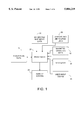
- FIG. 1 is a diagram of a generally preferred arrangement of components of an embodiment of a system of the present invention.
- FIG. 2 is a diagram of the presently preferred contents of an element of the diagram of FIG. 1.
- FIG. 3 is a diagram of the presently preferred contents of another element of the diagram of FIG. 1.
- FIG. 4 is a diagram representing a portion of the presently preferred display and command hierarchy of an embodiment of a system of the present invention.
- FIG. 5 is a diagram representing another portion of the presently preferred command hierarchy of an embodiment of a system of the present invention.
- FIG. 6 is a diagram representing yet another portion of the presently preferred command hierarchy of an embodiment of a system of the present invention.
- FIG. 7 is a diagram representing still another portion of the presently preferred command hierarchy of an embodiment of a system of the present invention.
- FIG. 8 is a diagram representing a portion of a presently preferred display configuration of an embodiment of a system of the present invention.
- FIG. 9 is a diagram showing another portion of a presently preferred display configuration of and embodiment of a system of the present invention.
- FIG. 10 is a diagram of still another portion of the presently preferred command hierarchy of an embodiment of a system of the present invention.
- FIG. 11 is a diagram showing yet another presently preferred display configuration of an embodiment of a system of the present invention.
- FIG. 1 shows a diagram of a presently preferred structure and arrangement for implementing a system according to the present invention.
- a processor 20 is connected to a data storage device or various date storage devices so as to receive data therefrom.
- Data stored for access by the processor 20 includes bit-mapped map image data 28, and preferably includes airport and air routing data 30 and magnetic variation data 32. These and other types of data may be organized in any desirable configuration for facilitating the operation of a navigation system of the present invention as described below.
- the data storage device used to hold the bit-mapped map image data 28 is presently preferred to be a CD-ROM. Read/write devices may also be employed, however, and portions of the bit-mapped map image data 28 are preferably temporarily retained or cached in other data storage devices for faster access as desired.
- Processor 20 is also connected to a data storage device so as to be able to store and retrieve data therefrom.
- a data storage device is presently preferred to be RAM or magnetic media or a combination thereof, or other similar memory.
- Flight plan data 34 is stored in such a device. Data such as flight plan data 34 is preferably preserved during loss of power. This may be accomplished by battery backed RAM, routine storage to a magnetic media, or other techniques as desired.
- the processor 20 is also connected to a display screen 24 for displaying map images and information to a user, and to at least one user input device 22 such as a keyboard, keypad, touchscreen, mouse, or the like to allow user input.
- a display screen 24 for displaying map images and information to a user
- at least one user input device 22 such as a keyboard, keypad, touchscreen, mouse, or the like to allow user input.
- Processor 20 is also connected to a global positioning system (GPS) receiver 26 for receiving global positioning information.
- GPS global positioning system
- the bit-mapped map image data 28 includes bit-mapped map image data of at least one map system, and preferably includes data of a plurality of map systems of mutually differing resolutions, such as map systems data 42, 44, and 46 shown in FIG. 2.
- the bit-mapped map image data is produced for a given map system by scanning the maps of the map system according to the procedure outlined in U.S. patent application Ser. No. 08/767,319 filed on Dec. 16, 1996 which is a continuation of application Ser. No. 08/432,992 filed May 2, 1995 and incorporated herein by reference.
- the scanning and image modification procedures disclosed in the above application allow standardization of bit-mapped image data for an entire map system, such that the processor 20 may use the data to display a bit-mapped map image centered at any latitude and longitude input to the processor, if within the map system, such that the map image essentially fills the display screen and contains no discontinuities except at the boundaries of the map system, if any.
- the map systems included in the presently preferred navigation system preferably include such systems as NOAA's world aeronautical charts, NOAA's sectional aeronautical charts, and the Defense Mapping Agency's world maps and the like.
- the airport and air routing data 30 preferably includes airport location data 48, airport runway data 52, airport services data 50, airport communications data 56, and various types of overlay data 54.
- Overlay data 54 preferably includes approach templates, instrument route charts, and other useful information in graphical or other form.
- the navigation system of FIG. 1 is operable in two main modes, a GPS track mode and a view maps mode as illustrated in FIG. 4.
- the processor 20 uses the bit-mapped map image data 28 to display a bit-mapped map image from a selected map system, with the map image essentially filling the display screen 24 and centered at a latitude and longitude supplied to the processor.
- the GPS track mode the latitude and longitude are supplied to the processor by the GPS receiver 26, so that the displayed map image is centered at the position of the navigation system as sensed by the GPS receiver 26.
- the view maps mode the latitude and longitude are supplied to the processor 20 by the user directly through the user input device 22 or from other data such as the airport and air routing data, as selected by the user through the user input device 22.
- the processor updates the displayed image each time it receives a new latitude and longitude.
- the latitude and longitude sensed by the GPS receiver changes periodically, and the map image is updated, giving the appearance of a single continuously scrolling map image moving across the surface of the display area of the display screen.
- the features displayed on the display screen in either GPS track mode or view maps mode may be divided into constant display features which are always shown on the screen and selective display features which are selectively shown on the screen in response to user inputs through the user input device.
- the preferred constant display features include the map image with a pointer or icon showing the position of the navigation system.
- the map image preferably is displayed over essentially the entire surface of the display area of the display screen, with the other constant display features occupying the relatively small remaining area.
- the icon is preferably an airplane, and may if desired be made to point along the displayed map image in the direction of the ground track as sensed by the GPS receiver.
- Other constant display features include menu headings in a menu bar, a map type and scale or zoom level window, a longitude and latitude window for displaying the current longitude and latitude of the pointer, a magnetic variation indicator to indicate when magnetic variation compensation is in use, and a map orientation indicator to indicate whether North-up or South-up map image orientation is in use.
- Selective display features which are displayed selectively according to user inputs through the user input device include a nearest airport window, a GPS receiver status window, a navigation information window, and a flight plan information window, and various types of overlay. In the view maps mode, the selective display features do not include the GPS receiver status and the navigation information windows, as illustrated in FIG. 4.
- the window-type selective display features are preferably displayed overlaying a peripheral portion of the bit-mapped map image.
- FIG. 11 represents the display area of a display screen.
- the bit-mapped map image occupies essentially all of the display area of the display screen, but with the four window-type selective display features overlaying the bit-mapped map image at the right peripheral edge thereof.
- Each of selective display features is individually selectively displayable. All may be displayed together as shown in FIG. 11, or any combination, or none, may be displayed, as selected by user inputs through the user input device.
- the great circle routes between waypoints along the route may be displayed on the bit-mapped map images.
- the current position of the navigation system is also shown, an the great circle route from the current position to the next waypoint may also be displayed.
- Such a display is shown schematically on the bit-mapped map image area in FIG. 11.
- a great circle route is shown graphically by a line overlaid on the display between waypoints 60 and 64.
- the actual position of the navigation system is shown by pointer 62, and the great circle route from the actual position to the next waypoint 64 is also shown by a line overlaid on the display.
- the overlay feature is not displayed in a particular location on the display area of the display screen. Instead, the overlay feature uses air routing data or other information to overlay various types of charts or information on the displayed map image in such a manner that the overlaid features correspond in size, position, and orientation to the features of the bit-mapped map image.
- Preferred charts for use with the overlay feature include approach templates for airports and instrument flight rules route charts. Such charts may be formatted in the air routing data as bit-mapped or vector graphics images, as desired.
- a special feature that improves the viewability of the overlaid information is that the bit-mapped map image may be dimmed while the overlaid information remains bright.
- bit-mapped map images for the maps displayed in the navigation system of the present invention, rather than raster graphics generated map images, allows quick access to the various images and low processing overhead to display and move the images.
- This enables the present system to be implemented with low cost processors, and to display moving map images quickly and accurately, with real-time display of the actual position of even a fast-moving vehicle such as an airplane.
- the present system is embodied in a laptop computer with a CD-ROM drive for the first storage device and a hard drive and RAM for the second storage device.
- a PCMIA-socket GPS receiver is employed, and the entire unit is then portable and, with batteries, cordless.
- the keyboard and other input devices of the laptop serve as the user input device.
- Processor power freed by the use of bit-mapped images is used instead to perform various other functions relating to the display of useful information along with the map images.
- bit-mapped map images also allows the inclusion of many more details than can practically be included in a vector-mapped graphics data base.
- the wealth of detail on the bit-mapped map images is provided without large processing power cost.
- pilots are provided with more information than with other navigational systems.
- FIGS. 5-7 Preferred command hierarchies for an embodiment of a navigation system of the present invention are shown in FIGS. 5-7.
- FIG. 5 preferred commands under each of the main menu headings are shown.
- Units allows a selection of the units of measure used in the various displays.
- Magnetic Variation toggles on and off the magnetic variation compensation.
- Reset GPS resets the GPS receiver.
- Switch Mode toggles between GPS tracking mode and view maps mode.
- Map Under Map, Change CD allows a CD containing bit-mapped map image data and other data to be changed for another. North/South Up toggles the orientation of the map images displayed. Auto Orientation provides an orientation with South-up if and only if the ground track (the direction of travel relative to the ground) is southward, otherwise a North-up orientation is provided. Map 1, Map 2, and Map 3 change the map system from which the currently displayed bit-mapped map image is sourced to the map system selected. Overlay calls the overlay commands shown in FIG. 6.
- Approach Plates or IFR Routes may be selected. Other useful types of information may also be included as additional selections. If Approach Plates is selected, the desired approach plate is preferably selected by first selecting an airport, then a runway at the selected airport. The runway may be selected by number or other designation by the Runway command, or by the types of navigation aid available by the Nav. Aid Types command. The appropriate approach plate is then overlaid on the displayed bit-mapped map image with corresponding features in proper alignment.
- Zoom commands allow zooming within a given map system. In and Out zoom one level in and out, respectively.
- the Level choices zoom directly to the indicated zoom level.
- the Goto commands allow motion around the map apart from GPS tracking and, when executed, automatically cause a switch to view maps mode.
- Latitude/Longitude allows entry of the latitude and longitude of the position to which the pointer will move.
- Airport allows selection of an airport by an official identifier (preferably by ICAO identifier) then moves the pointer to the selected airport. Nearest airport moves the pointer to the nearest airport, while the choices numbered 1-5 move the pointer to the selected one of the five next nearest airports.
- the Info command allows selection of an airport as with the Goto commands, but the destination airport (the destination of a currently selected flight plan) is an additional choice.
- Choice of an airport under the Info command results in display of the information screen or information mode shown in FIG. 9, and in the further command hierarchy shown in FIG. 10.
- the information screen shown in FIG. 9 includes an airport information window containing information about the selected airport, a runway information window containing information about a selected runway at the selected airport, and a communications information/runway sketch window, containing either information about a selected communications channel of the selected airport, or a sketch of the runways of the selected airport.
- the airport information provided in the airport information window is preferably thorough and detailed, including such information as ownership status (civil, military, civil/military, or private), name, City, State, Country, reference longitude and latitude and elevation, magnetic variation, longest runway length and surface type, above ground height for the airport traffic pattern, services and supplies available such as oxygen types, fuel types, repair types, IFR capability, etc., and the airport record date.
- ownership status civil, military, civil/military, or private
- name City, State, Country
- reference longitude and latitude and elevation magnetic variation
- longest runway length and surface type above ground height for the airport traffic pattern
- services and supplies available such as oxygen types, fuel types, repair types, IFR capability, etc.
- the runway information provided in the runway information window is preferably similarly detailed, including such things as the runway identifier, the runway longitude and latitude, the length and width of the runway, the true and magnetic bearings of the runway, the surface type, the lighting type, and the direction of turns for traffic flow.
- the runway sketch when shown, gives a representation of the runways with true north up, the runway identifiers displayed near each runway, and the selected runway highlighted.
- the communications information when shown, provides details concerning the communications frequencies of the selected airport, including the number of channels, their call signs, types, and frequencies, and any services provided by or on each frequency.
- the command hierarchy shown in FIG. 10 is used to control the display of the information screen. Exit exits the information screen. Airport allows a different airport to be selected. The selections under Communications allow the communications frequencies to be displayed (Show) and allow toggling to the Next or to the Previous frequency. The selections under Runway allow the runway diagram to be displayed (Show) and allow toggling to the Next or to the Previous runway.
- the selections under Plan allow modifications to the current flight plan.
- Add Waypoint allows a waypoint to be added after the current point.
- Add Destination allows a destination to be added at the end of the current plan.
- Remove Waypoint removes the current waypoint.
- Next Waypoint and Previous Waypoint toggle to the next and previous waypoints respectively.
- Plan Display toggles open and closed the flight plan information window shown in FIG. 11.
- Virtual Flight causes the bit-mapped map image display to track through the current flight plan, employing and displaying the great circle route between waypoints. Flight Plan brings up a command list like that of FIG. 7 and a display as shown in FIG. 8.
- the preferred flight plan display represented in FIG. 8 is a window having column headings across the top of "leg,” “from,” “to,” “distance,” and “heading.” Multiple (preferably at least three) legs of the flight plan are preferably displayed under these headings. The layout of information on the middle leg is shown, with the top and bottom legs omitted for clarity.
- the leg information includes the ICAO identifiers of the waypoints, and the distance and heading from the "from" way point to the "to” waypoint. Under the ICAO identifiers is displayed the name of the "to" waypoint.
- plan leg information a display of the startpoint of the plan, the destination of the plan, and the total distance of the plan. Below that is a display of the plan number and name, and the total number of waypoints in the plan.
- Plan Toggle toggles up or down to other plans.
- Waypoint Toggle toggles up or down to other legs within a plan, with the selected leg highlighted.
- Cancel changes allows canceling all of current editing performed on a flight plan. Enter causes the changes in the currently edited flight plan to be stored, replacing the previous version. Destination adds a destination to the end of the currently displayed flight plan. Delete deletes a currently highlighted leg of a flight plan. Insert inserts a new leg after the currently highlighted leg of the flight plan. Reverse reverses the current flight plan. Clear clears the current flight plan from the second memory device.
- Edit allows editing of the highlighted leg of the flight plan. Name allows giving of or editing of a name for the current flight plan. View forces the map image display into view maps mode and places the pointer at the location of the highlighted waypoint or destination.
Abstract
Description
Claims (24)
Priority Applications (8)
| Application Number | Priority Date | Filing Date | Title |
|---|---|---|---|
| US08/728,617 US5884219A (en) | 1996-10-10 | 1996-10-10 | Moving map navigation system |
| US08/943,838 US6199015B1 (en) | 1996-10-10 | 1997-10-03 | Map-based navigation system with overlays |
| CA002268065A CA2268065A1 (en) | 1996-10-10 | 1997-10-10 | Map-based navigation system with overlays |
| EP97947268A EP0944872A4 (en) | 1996-10-10 | 1997-10-10 | Map-based navigation system with overlays |
| PCT/US1997/019017 WO1998015912A1 (en) | 1996-10-10 | 1997-10-10 | Map-based navigation system with overlays |
| JP51781598A JP2001525053A (en) | 1996-10-10 | 1997-10-10 | Navigation system based on map with overlay |
| AU52389/98A AU728762B2 (en) | 1996-10-10 | 1997-10-10 | Map-based navigation system with overlays |
| US09/450,481 US6314370B1 (en) | 1996-10-10 | 1999-11-29 | Map-based navigation system with overlays |
Applications Claiming Priority (1)
| Application Number | Priority Date | Filing Date | Title |
|---|---|---|---|
| US08/728,617 US5884219A (en) | 1996-10-10 | 1996-10-10 | Moving map navigation system |
Related Child Applications (2)
| Application Number | Title | Priority Date | Filing Date |
|---|---|---|---|
| US08/943,838 Continuation US6199015B1 (en) | 1996-10-10 | 1997-10-03 | Map-based navigation system with overlays |
| US08/943,838 Continuation-In-Part US6199015B1 (en) | 1996-10-10 | 1997-10-03 | Map-based navigation system with overlays |
Publications (1)
| Publication Number | Publication Date |
|---|---|
| US5884219A true US5884219A (en) | 1999-03-16 |
Family
ID=24927580
Family Applications (1)
| Application Number | Title | Priority Date | Filing Date |
|---|---|---|---|
| US08/728,617 Expired - Lifetime US5884219A (en) | 1996-10-10 | 1996-10-10 | Moving map navigation system |
Country Status (1)
| Country | Link |
|---|---|
| US (1) | US5884219A (en) |
Cited By (56)
| Publication number | Priority date | Publication date | Assignee | Title |
|---|---|---|---|---|
| US6021374A (en) * | 1997-10-09 | 2000-02-01 | Mcdonnell Douglas Corporation | Stand alone terrain conflict detector and operating methods therefor |
| WO2000007132A1 (en) * | 1998-07-30 | 2000-02-10 | The Government Of The United States Of America, Represented By The Secretary Of The Navy Naval Research Laboratory | Moving map composer (mmc) |
| US6038510A (en) * | 1996-08-08 | 2000-03-14 | Samsung Electronics Co., Ltd. | Method for displaying current position of moving object in navigation device in accordance with position condition of moving object |
| US6188956B1 (en) * | 1998-12-30 | 2001-02-13 | Garmin Corporation | Navigation device and method for selectively displaying thoroughfare names |
| US6208307B1 (en) | 2000-04-07 | 2001-03-27 | Live Tv, Inc. | Aircraft in-flight entertainment system having wideband antenna steering and associated methods |
| US6216065B1 (en) | 1999-08-06 | 2001-04-10 | Bell Helicopter Textron Inc. | Method and system for creating an approach to a position on the ground from a location above the ground |
| US6240361B1 (en) * | 1997-08-08 | 2001-05-29 | Alpine Electronics, Inc. | Navigation apparatus |
| US6256585B1 (en) | 1999-10-14 | 2001-07-03 | U.S. Army Corps Of Engineers As Represented By The Secretary Of The Army | Method for measuring depths of a waterway and for determining vertical positions of a waterborne vessel |
| US20010026271A1 (en) * | 2000-03-29 | 2001-10-04 | Higgins Darin Wayne | System and method for synchronizing raster and vector map images |
| US20010033291A1 (en) * | 2000-03-29 | 2001-10-25 | Scott Dan Martin | System and method for georeferencing digital raster maps |
| US6314370B1 (en) * | 1996-10-10 | 2001-11-06 | Ames Maps, Llc | Map-based navigation system with overlays |
| US6317689B1 (en) * | 2000-02-09 | 2001-11-13 | Garmin Corporation | Method and device for displaying animated navigation information |
| US20020109729A1 (en) * | 2000-12-14 | 2002-08-15 | Rabindranath Dutta | Integrating content with virtual advertisements using vector graphics images obtainable on the web |
| US6456941B1 (en) | 2001-03-26 | 2002-09-24 | William Gutierrez | System and method for aircraft and watercraft control and collision prevention |
| US6476780B2 (en) * | 1997-01-07 | 2002-11-05 | Honda Giken Kogyo Kabushiki Kaisha | Road image display device |
| FR2826140A1 (en) * | 2001-06-19 | 2002-12-20 | Thales Sa | Management of man-machine interface in a cartographic environment associated with an aircraft, uses tree-structured information with single button control to allow the user to move through the levels of the tree |
| US6523024B1 (en) * | 1994-03-18 | 2003-02-18 | Hitachi, Ltd. | Methods for retrieving database with image information |
| US20030192052A1 (en) * | 2000-04-07 | 2003-10-09 | Live Tv, Inc. | Aircraft in-flight entertainment system generating a pricing structure for available features, and associated methods |
| US20030200547A1 (en) * | 2000-04-07 | 2003-10-23 | Live Tv, Inc. | Aircraft in-flight entertainment system receiving terrestrial television broadcast signals and associated methods |
| US20030200546A1 (en) * | 2000-04-07 | 2003-10-23 | Live Tv, Inc. | Aircraft system providing passenger entertainment and surveillance features, and associated methods |
| US6643580B1 (en) * | 1998-10-16 | 2003-11-04 | Universal Avionics Systems Corporation | Flight plan intent alert system and method |
| US20030229897A1 (en) * | 2000-04-07 | 2003-12-11 | Live Tv, Inc. | Aircraft in-flight entertainment system providing passenger specific advertisements, and associated methods |
| US20030233658A1 (en) * | 2000-04-07 | 2003-12-18 | Live Tv, Inc. | Aircraft in-flight entertainment system providing weather information and associated methods |
| US20040078821A1 (en) * | 2000-04-07 | 2004-04-22 | Live Tv, Inc. | Aircraft in-flight entertainment system with soft fail and flight information features and associated methods |
| US6748597B1 (en) | 2000-04-07 | 2004-06-08 | Live Tv, Inc. | Upgradable aircraft in-flight entertainment system and associated upgrading methods |
| US6751801B1 (en) | 2000-04-07 | 2004-06-15 | Live Tv, Inc. | Aircraft in-flight entertainment system having enhanced antenna steering and associated methods |
| US20050192717A1 (en) * | 2004-02-26 | 2005-09-01 | Tafs William D. | Methods and systems for automatically tracking information during flight |
| US20050222721A1 (en) * | 2004-03-31 | 2005-10-06 | Chen Sherwin S | Systems and methods for handling the display and receipt of aircraft control information |
| US20050228674A1 (en) * | 2004-03-31 | 2005-10-13 | Gunn Peter D | Methods and systems for displaying assistance messages to aircraft operators |
| US20060005147A1 (en) * | 2004-06-30 | 2006-01-05 | Hammack Jason L | Methods and systems for controlling the display of maps aboard an aircraft |
| US20060007232A1 (en) * | 2004-07-07 | 2006-01-12 | Layne Geary J | System and method for smoothing and compression of polyline data |
| US20060009955A1 (en) * | 2004-07-07 | 2006-01-12 | Gendron Marlin L | System, method and apparatus for clustering features |
| US20060200587A1 (en) * | 1997-02-25 | 2006-09-07 | Hindman George W | Apparatus and method for a mobile navigation computer |
| US20060212221A1 (en) * | 2005-03-16 | 2006-09-21 | Chun-Sam Liu | Golfing aid device capable of displaying and setting points-of-interest |
| US20070103461A1 (en) * | 2005-11-08 | 2007-05-10 | Sony Corporation | Virtual space image display method, apparatus, virtual space image display program, and recording medium |
| US20070176796A1 (en) * | 2005-11-07 | 2007-08-02 | Google Inc. | Local Search and Mapping for Mobile Devices |
| US20080091311A1 (en) * | 2003-12-24 | 2008-04-17 | The Boeing Company | Apparatuses and methods for displaying and receiving tactical and strategic flight guidance information |
| EP1930695A2 (en) * | 2006-12-06 | 2008-06-11 | VDO Automotive AG | Method and device for operating a navigational device |
| US20090062972A1 (en) * | 2003-12-24 | 2009-03-05 | The Boeing Company | Systems and Methods for Presenting and Obtaining Flight Control Information |
| US20090076719A1 (en) * | 2002-05-03 | 2009-03-19 | Pixearth Corporation | System to navigate within images spatially referenced to a computed space |
| US20090105943A1 (en) * | 2007-10-19 | 2009-04-23 | Airbus France | Method and device for creating an aircraft flight plan |
| US7580235B2 (en) | 2004-10-12 | 2009-08-25 | The Boeing Company | Systems and methods for monitoring and controlling circuit breakers |
| US20100076628A1 (en) * | 2002-09-20 | 2010-03-25 | The Boeing Company | Apparatuses and methods for displaying autoflight information |
| US20100125403A1 (en) * | 2008-11-14 | 2010-05-20 | Clark Samuel T | Display of Taxi Route Control Point Information |
| USRE41396E1 (en) | 2004-06-17 | 2010-06-22 | The Boeing Company | Method and system for entering and displaying ground taxi instructions |
| US20100217458A1 (en) * | 2007-06-28 | 2010-08-26 | Airbus Operations Gmbh | Interactive information system for an airplane |
| US20100250117A1 (en) * | 2009-03-27 | 2010-09-30 | Thales | Device for Flight Plan Display with Displacement Based on Jumps |
| US7908080B2 (en) | 2004-12-31 | 2011-03-15 | Google Inc. | Transportation routing |
| US7974775B1 (en) * | 1999-11-05 | 2011-07-05 | Angela Masson | Electronic kit bag |
| US8180562B2 (en) | 2008-06-04 | 2012-05-15 | The Boeing Company | System and method for taxi route entry parsing |
| US20150123837A1 (en) * | 2012-06-15 | 2015-05-07 | Lufthansa Technik Ag | Method and passenger information system for providing flight information data |
| US9074848B1 (en) * | 2011-04-13 | 2015-07-07 | Litel Instruments | Precision geographic location system and method utilizing an image product |
| US9410819B2 (en) | 2011-08-02 | 2016-08-09 | The Boeing Company | Management system for aeronautical information |
| US10955558B2 (en) * | 2003-01-16 | 2021-03-23 | Adidas Ag | Systems and methods for electronically sharing information about health-related activities |
| CN112685679A (en) * | 2021-01-08 | 2021-04-20 | 合肥大明智联科技股份有限公司 | Large-range one-web webpage splicing display equipment method based on map API |
| US11481091B2 (en) * | 2013-05-15 | 2022-10-25 | Google Llc | Method and apparatus for supporting user interactions with non- designated locations on a digital map |
Citations (28)
| Publication number | Priority date | Publication date | Assignee | Title |
|---|---|---|---|---|
| US4400727A (en) * | 1981-11-27 | 1983-08-23 | The Bendix Corporation | Moving map display |
| US4470119A (en) * | 1981-07-07 | 1984-09-04 | Nippondenso Co., Ltd. | Mobile navigator |
| US4484192A (en) * | 1981-12-17 | 1984-11-20 | The Bendix Corporation | Moving map display |
| US4513377A (en) * | 1981-06-11 | 1985-04-23 | Nippondenso Co., Ltd. | Vehicle-mounted navigator |
| US4571684A (en) * | 1983-03-25 | 1986-02-18 | Nippondenso Co., Ltd. | Map display system for vehicles |
| US4675676A (en) * | 1983-03-09 | 1987-06-23 | Nippondenso Co. Ltd. | Map display system |
| US4737927A (en) * | 1985-04-30 | 1988-04-12 | Nippondenso Co., Ltd. | Map display apparatus |
| US4737916A (en) * | 1985-04-30 | 1988-04-12 | Nippondenso Co., Ltd. | Electronic map display system |
| US4796190A (en) * | 1986-06-04 | 1989-01-03 | Cummings Elihu C | Navigation system |
| US4847788A (en) * | 1985-03-01 | 1989-07-11 | Hitachi, Ltd. | Graphic data processing method and system |
| US5059970A (en) * | 1989-03-14 | 1991-10-22 | Invention Factory (Proprietary) Limited | Navigational aid |
| EP0452613A2 (en) * | 1990-04-17 | 1991-10-23 | Pioneer Electronic Corporation | Image information display apparatus |
| US5067081A (en) * | 1989-08-30 | 1991-11-19 | Person Carl E | Portable electronic navigation aid |
| US5115399A (en) * | 1987-12-28 | 1992-05-19 | Kabushiki Kaisha Shinsangyokaihatsu | Position input system for vehicular navigation apparatus |
| EP0534755A2 (en) * | 1991-09-27 | 1993-03-31 | Pioneer Electronic Corporation | Navigation device |
| EP0539145A1 (en) * | 1991-10-22 | 1993-04-28 | Pioneer Electronic Corporation | Navigation device |
| EP0539143A2 (en) * | 1991-10-22 | 1993-04-28 | Pioneer Electronic Corporation | Navigation system |
| EP0539146A2 (en) * | 1991-10-22 | 1993-04-28 | Pioneer Electronic Corporation | Navigation system |
| EP0559355A1 (en) * | 1992-02-18 | 1993-09-08 | Pioneer Electronic Corporation | Navigation apparatus with enhanced positional display function |
| US5283562A (en) * | 1990-04-17 | 1994-02-01 | Pioneer Electronic Corporation | Map display apparatus |
| EP0601712A1 (en) * | 1992-11-12 | 1994-06-15 | Pioneer Electronic Corporation | Navigation system |
| US5341463A (en) * | 1990-01-31 | 1994-08-23 | The United States Of America As Represented By The Secretary Of The Navy | Selective polygon map display method |
| US5369735A (en) * | 1990-03-30 | 1994-11-29 | New Microtime Inc. | Method for controlling a 3D patch-driven special effects system |
| US5465323A (en) * | 1989-09-20 | 1995-11-07 | Association Scientifique Pour La Geologie Et De Ses Applications | Method for modelling a surface and device for implementing same |
| US5519392A (en) * | 1992-07-31 | 1996-05-21 | Sextant Avionique | Method and device for assisting navigation |
| US5543802A (en) * | 1993-03-01 | 1996-08-06 | Motorola, Inc. | Position/navigation device and method |
| US5559707A (en) * | 1994-06-24 | 1996-09-24 | Delorme Publishing Company | Computer aided routing system |
| US5696684A (en) * | 1991-07-04 | 1997-12-09 | Robert Bosch Gmbh | Electronic guide device |
-
1996
- 1996-10-10 US US08/728,617 patent/US5884219A/en not_active Expired - Lifetime
Patent Citations (28)
| Publication number | Priority date | Publication date | Assignee | Title |
|---|---|---|---|---|
| US4513377A (en) * | 1981-06-11 | 1985-04-23 | Nippondenso Co., Ltd. | Vehicle-mounted navigator |
| US4470119A (en) * | 1981-07-07 | 1984-09-04 | Nippondenso Co., Ltd. | Mobile navigator |
| US4400727A (en) * | 1981-11-27 | 1983-08-23 | The Bendix Corporation | Moving map display |
| US4484192A (en) * | 1981-12-17 | 1984-11-20 | The Bendix Corporation | Moving map display |
| US4675676A (en) * | 1983-03-09 | 1987-06-23 | Nippondenso Co. Ltd. | Map display system |
| US4571684A (en) * | 1983-03-25 | 1986-02-18 | Nippondenso Co., Ltd. | Map display system for vehicles |
| US4847788A (en) * | 1985-03-01 | 1989-07-11 | Hitachi, Ltd. | Graphic data processing method and system |
| US4737916A (en) * | 1985-04-30 | 1988-04-12 | Nippondenso Co., Ltd. | Electronic map display system |
| US4737927A (en) * | 1985-04-30 | 1988-04-12 | Nippondenso Co., Ltd. | Map display apparatus |
| US4796190A (en) * | 1986-06-04 | 1989-01-03 | Cummings Elihu C | Navigation system |
| US5115399A (en) * | 1987-12-28 | 1992-05-19 | Kabushiki Kaisha Shinsangyokaihatsu | Position input system for vehicular navigation apparatus |
| US5059970A (en) * | 1989-03-14 | 1991-10-22 | Invention Factory (Proprietary) Limited | Navigational aid |
| US5067081A (en) * | 1989-08-30 | 1991-11-19 | Person Carl E | Portable electronic navigation aid |
| US5465323A (en) * | 1989-09-20 | 1995-11-07 | Association Scientifique Pour La Geologie Et De Ses Applications | Method for modelling a surface and device for implementing same |
| US5341463A (en) * | 1990-01-31 | 1994-08-23 | The United States Of America As Represented By The Secretary Of The Navy | Selective polygon map display method |
| US5369735A (en) * | 1990-03-30 | 1994-11-29 | New Microtime Inc. | Method for controlling a 3D patch-driven special effects system |
| EP0452613A2 (en) * | 1990-04-17 | 1991-10-23 | Pioneer Electronic Corporation | Image information display apparatus |
| US5283562A (en) * | 1990-04-17 | 1994-02-01 | Pioneer Electronic Corporation | Map display apparatus |
| US5696684A (en) * | 1991-07-04 | 1997-12-09 | Robert Bosch Gmbh | Electronic guide device |
| EP0534755A2 (en) * | 1991-09-27 | 1993-03-31 | Pioneer Electronic Corporation | Navigation device |
| EP0539143A2 (en) * | 1991-10-22 | 1993-04-28 | Pioneer Electronic Corporation | Navigation system |
| EP0539146A2 (en) * | 1991-10-22 | 1993-04-28 | Pioneer Electronic Corporation | Navigation system |
| EP0539145A1 (en) * | 1991-10-22 | 1993-04-28 | Pioneer Electronic Corporation | Navigation device |
| EP0559355A1 (en) * | 1992-02-18 | 1993-09-08 | Pioneer Electronic Corporation | Navigation apparatus with enhanced positional display function |
| US5519392A (en) * | 1992-07-31 | 1996-05-21 | Sextant Avionique | Method and device for assisting navigation |
| EP0601712A1 (en) * | 1992-11-12 | 1994-06-15 | Pioneer Electronic Corporation | Navigation system |
| US5543802A (en) * | 1993-03-01 | 1996-08-06 | Motorola, Inc. | Position/navigation device and method |
| US5559707A (en) * | 1994-06-24 | 1996-09-24 | Delorme Publishing Company | Computer aided routing system |
Non-Patent Citations (4)
| Title |
|---|
| Adobe Photoshop Version 2.5 for Windows User Guide, 1993 Adobe Systems Incorporated, pp.79 90. * |
| Adobe Photoshop Version 2.5 for Windows User Guide, 1993 Adobe Systems Incorporated, pp.79-90. |
| Foley, James D. et al., Second Edition Computer Graphics Principles and Practice, Addison Wesley Publishing Company, Inc. 1991, pp. 9 13. * |
| Foley, James D. et al., Second Edition Computer Graphics Principles and Practice, Addison-Wesley Publishing Company, Inc. 1991, pp. 9-13. |
Cited By (123)
| Publication number | Priority date | Publication date | Assignee | Title |
|---|---|---|---|---|
| US6523024B1 (en) * | 1994-03-18 | 2003-02-18 | Hitachi, Ltd. | Methods for retrieving database with image information |
| US20030088561A1 (en) * | 1994-03-18 | 2003-05-08 | Hitachi, Ltd. | Methods for retrieving database with image information |
| US6038510A (en) * | 1996-08-08 | 2000-03-14 | Samsung Electronics Co., Ltd. | Method for displaying current position of moving object in navigation device in accordance with position condition of moving object |
| US6314370B1 (en) * | 1996-10-10 | 2001-11-06 | Ames Maps, Llc | Map-based navigation system with overlays |
| US6476780B2 (en) * | 1997-01-07 | 2002-11-05 | Honda Giken Kogyo Kabushiki Kaisha | Road image display device |
| US20060200587A1 (en) * | 1997-02-25 | 2006-09-07 | Hindman George W | Apparatus and method for a mobile navigation computer |
| US7805542B2 (en) | 1997-02-25 | 2010-09-28 | George W. Hindman | Mobile unit attached in a mobile environment that fully restricts access to data received via wireless signal to a separate computer in the mobile environment |
| US6240361B1 (en) * | 1997-08-08 | 2001-05-29 | Alpine Electronics, Inc. | Navigation apparatus |
| US6021374A (en) * | 1997-10-09 | 2000-02-01 | Mcdonnell Douglas Corporation | Stand alone terrain conflict detector and operating methods therefor |
| US6218965B1 (en) * | 1998-07-30 | 2001-04-17 | The United States Of America As Represented By The Secretary Of The Navy | Moving map composer (MMC) |
| WO2000007132A1 (en) * | 1998-07-30 | 2000-02-10 | The Government Of The United States Of America, Represented By The Secretary Of The Navy Naval Research Laboratory | Moving map composer (mmc) |
| US6643580B1 (en) * | 1998-10-16 | 2003-11-04 | Universal Avionics Systems Corporation | Flight plan intent alert system and method |
| US6188956B1 (en) * | 1998-12-30 | 2001-02-13 | Garmin Corporation | Navigation device and method for selectively displaying thoroughfare names |
| US6216065B1 (en) | 1999-08-06 | 2001-04-10 | Bell Helicopter Textron Inc. | Method and system for creating an approach to a position on the ground from a location above the ground |
| US6256585B1 (en) | 1999-10-14 | 2001-07-03 | U.S. Army Corps Of Engineers As Represented By The Secretary Of The Army | Method for measuring depths of a waterway and for determining vertical positions of a waterborne vessel |
| US7974775B1 (en) * | 1999-11-05 | 2011-07-05 | Angela Masson | Electronic kit bag |
| US8301368B1 (en) * | 1999-11-05 | 2012-10-30 | Angela Masson | Electronic kit bag |
| US6397148B1 (en) | 2000-02-09 | 2002-05-28 | Garmin Corporation | Method and device for displaying animated navigation information |
| US6434484B1 (en) | 2000-02-09 | 2002-08-13 | Garmin Corporation | Method and device for displaying animated navigation information |
| US6317689B1 (en) * | 2000-02-09 | 2001-11-13 | Garmin Corporation | Method and device for displaying animated navigation information |
| US20010033291A1 (en) * | 2000-03-29 | 2001-10-25 | Scott Dan Martin | System and method for georeferencing digital raster maps |
| US20010033290A1 (en) * | 2000-03-29 | 2001-10-25 | Scott Dan Martin | System and method for georeferencing digial raster maps |
| US7148898B1 (en) | 2000-03-29 | 2006-12-12 | Sourceprose Corporation | System and method for synchronizing raster and vector map images |
| US20030052896A1 (en) * | 2000-03-29 | 2003-03-20 | Higgins Darin Wayne | System and method for synchronizing map images |
| US20010026270A1 (en) * | 2000-03-29 | 2001-10-04 | Higgins Darin Wayne | System and method for synchronizing raster and vector map images |
| US7161604B2 (en) | 2000-03-29 | 2007-01-09 | Sourceprose Corporation | System and method for synchronizing raster and vector map images |
| US7167187B2 (en) | 2000-03-29 | 2007-01-23 | Sourceprose Corporation | System and method for georeferencing digital raster maps using a georeferencing function |
| US7190377B2 (en) | 2000-03-29 | 2007-03-13 | Sourceprose Corporation | System and method for georeferencing digital raster maps with resistance to potential errors |
| US20010026271A1 (en) * | 2000-03-29 | 2001-10-04 | Higgins Darin Wayne | System and method for synchronizing raster and vector map images |
| US7142217B2 (en) | 2000-03-29 | 2006-11-28 | Sourceprose Corporation | System and method for synchronizing raster and vector map images |
| US7587733B2 (en) | 2000-04-07 | 2009-09-08 | Livetv, Llc | Aircraft in-flight entertainment system providing weather information and associated methods |
| US20030233658A1 (en) * | 2000-04-07 | 2003-12-18 | Live Tv, Inc. | Aircraft in-flight entertainment system providing weather information and associated methods |
| US20040078821A1 (en) * | 2000-04-07 | 2004-04-22 | Live Tv, Inc. | Aircraft in-flight entertainment system with soft fail and flight information features and associated methods |
| US6748597B1 (en) | 2000-04-07 | 2004-06-08 | Live Tv, Inc. | Upgradable aircraft in-flight entertainment system and associated upgrading methods |
| US6751801B1 (en) | 2000-04-07 | 2004-06-15 | Live Tv, Inc. | Aircraft in-flight entertainment system having enhanced antenna steering and associated methods |
| US20030229897A1 (en) * | 2000-04-07 | 2003-12-11 | Live Tv, Inc. | Aircraft in-flight entertainment system providing passenger specific advertisements, and associated methods |
| US20030200546A1 (en) * | 2000-04-07 | 2003-10-23 | Live Tv, Inc. | Aircraft system providing passenger entertainment and surveillance features, and associated methods |
| US20030200547A1 (en) * | 2000-04-07 | 2003-10-23 | Live Tv, Inc. | Aircraft in-flight entertainment system receiving terrestrial television broadcast signals and associated methods |
| US8803971B2 (en) | 2000-04-07 | 2014-08-12 | Livetv, Llc | Aircraft system providing passenger entertainment and surveillance features, and associated methods |
| US20030192052A1 (en) * | 2000-04-07 | 2003-10-09 | Live Tv, Inc. | Aircraft in-flight entertainment system generating a pricing structure for available features, and associated methods |
| US7707612B2 (en) | 2000-04-07 | 2010-04-27 | Live Tv, Inc. | Aircraft in-flight entertainment system with soft fail and flight information features and associated methods |
| US6208307B1 (en) | 2000-04-07 | 2001-03-27 | Live Tv, Inc. | Aircraft in-flight entertainment system having wideband antenna steering and associated methods |
| US20020109729A1 (en) * | 2000-12-14 | 2002-08-15 | Rabindranath Dutta | Integrating content with virtual advertisements using vector graphics images obtainable on the web |
| US6456941B1 (en) | 2001-03-26 | 2002-09-24 | William Gutierrez | System and method for aircraft and watercraft control and collision prevention |
| US6643579B1 (en) | 2001-03-26 | 2003-11-04 | William Gutierrez | System and method for aircraft and watercraft control and collision prevention |
| US20040148066A1 (en) * | 2001-06-19 | 2004-07-29 | Erick Coppolino | Method of managing a man/machine interface in a cartographic system that is at least partially located on-board an aircraft |
| FR2826140A1 (en) * | 2001-06-19 | 2002-12-20 | Thales Sa | Management of man-machine interface in a cartographic environment associated with an aircraft, uses tree-structured information with single button control to allow the user to move through the levels of the tree |
| WO2002103507A1 (en) * | 2001-06-19 | 2002-12-27 | Thales | Method of managing a man/machine interface in a cartographic system that is at least partially located on-board an aircraft |
| US20090076719A1 (en) * | 2002-05-03 | 2009-03-19 | Pixearth Corporation | System to navigate within images spatially referenced to a computed space |
| US8635557B2 (en) * | 2002-05-03 | 2014-01-21 | 205 Ridgmont Solutions, L.L.C. | System to navigate within images spatially referenced to a computed space |
| US8494691B2 (en) | 2002-09-20 | 2013-07-23 | The Boeing Company | Apparatuses and methods for displaying autoflight information |
| US20100076628A1 (en) * | 2002-09-20 | 2010-03-25 | The Boeing Company | Apparatuses and methods for displaying autoflight information |
| US20110125347A1 (en) * | 2002-09-20 | 2011-05-26 | The Boeing Company | Apparatuses and methods for displaying autoflight information |
| US7970502B2 (en) | 2002-09-20 | 2011-06-28 | The Boeing Company | Apparatuses and systems for controlling autoflight systems |
| US10955558B2 (en) * | 2003-01-16 | 2021-03-23 | Adidas Ag | Systems and methods for electronically sharing information about health-related activities |
| US8005582B2 (en) | 2003-12-24 | 2011-08-23 | The Boeing Company | Apparatuses and methods for displaying and receiving tactical and strategic flight guidance information |
| US20100076627A1 (en) * | 2003-12-24 | 2010-03-25 | The Boeing Company | Apparatuses and methods for displaying and receiving tactical and strategic flight guidance information |
| US8364329B2 (en) | 2003-12-24 | 2013-01-29 | The Boeing Company | Apparatuses and methods for displaying and receiving tactical and strategic flight guidance information |
| US20110224848A1 (en) * | 2003-12-24 | 2011-09-15 | The Boeing Company | Apparatuses and methods for displaying and receiving tactical and strategic flight guidance information |
| US8121745B2 (en) | 2003-12-24 | 2012-02-21 | The Boeing Company | Apparatuses and methods for displaying and receiving tactical and strategic flight guidance information |
| US20080091311A1 (en) * | 2003-12-24 | 2008-04-17 | The Boeing Company | Apparatuses and methods for displaying and receiving tactical and strategic flight guidance information |
| US7945354B2 (en) | 2003-12-24 | 2011-05-17 | The Boeing Company | Apparatuses and methods for displaying and receiving tactical and strategic flight guidance information |
| US7751948B2 (en) | 2003-12-24 | 2010-07-06 | The Boeing Company | Apparatuses and methods for displaying and receiving tactical and strategic flight guidance information |
| US20100262358A1 (en) * | 2003-12-24 | 2010-10-14 | The Boeing Company | Apparatuses and methods for displaying and receiving tactical and strategic flight guidance information |
| US8135501B2 (en) | 2003-12-24 | 2012-03-13 | The Boeing Company | Apparatuses and methods for displaying and receiving tactical and strategic flight guidance information |
| US20090062972A1 (en) * | 2003-12-24 | 2009-03-05 | The Boeing Company | Systems and Methods for Presenting and Obtaining Flight Control Information |
| US8504223B2 (en) | 2003-12-24 | 2013-08-06 | The Boeing Company | Systems and methods for presenting and obtaining flight control information |
| US20050192717A1 (en) * | 2004-02-26 | 2005-09-01 | Tafs William D. | Methods and systems for automatically tracking information during flight |
| US7577501B2 (en) | 2004-02-26 | 2009-08-18 | The Boeing Company | Methods and systems for automatically tracking information during flight |
| US8082070B2 (en) | 2004-03-31 | 2011-12-20 | The Boeing Company | Methods and systems for displaying assistance messages to aircraft operators |
| US20080316058A1 (en) * | 2004-03-31 | 2008-12-25 | The Boeing Company | Systems and Methods for Handling the Display and Receipt of Aircraft Control Information |
| US7751947B2 (en) | 2004-03-31 | 2010-07-06 | The Boeing Company | Methods and systems for displaying assistance messages to aircraft operators |
| US8290643B2 (en) | 2004-03-31 | 2012-10-16 | The Boeing Company | Systems and methods for handling the display and receipt of aircraft control information |
| US20050222721A1 (en) * | 2004-03-31 | 2005-10-06 | Chen Sherwin S | Systems and methods for handling the display and receipt of aircraft control information |
| US20050228674A1 (en) * | 2004-03-31 | 2005-10-13 | Gunn Peter D | Methods and systems for displaying assistance messages to aircraft operators |
| US20100262319A1 (en) * | 2004-03-31 | 2010-10-14 | The Boeing Company | Methods and systems for displaying assistance messages to aircraft operators |
| US7844372B2 (en) | 2004-03-31 | 2010-11-30 | The Boeing Company | Systems and methods for handling the display and receipt of aircraft control information |
| US20110060484A1 (en) * | 2004-03-31 | 2011-03-10 | The Boeing Company | Systems and methods for handling the display and receipt of aircraft control information |
| US8032270B2 (en) | 2004-03-31 | 2011-10-04 | The Boeing Company | Systems and methods for handling the display and receipt of aircraft control information |
| US7418319B2 (en) | 2004-03-31 | 2008-08-26 | The Boeing Company | Systems and methods for handling the display and receipt of aircraft control information |
| USRE41396E1 (en) | 2004-06-17 | 2010-06-22 | The Boeing Company | Method and system for entering and displaying ground taxi instructions |
| US20060005147A1 (en) * | 2004-06-30 | 2006-01-05 | Hammack Jason L | Methods and systems for controlling the display of maps aboard an aircraft |
| US7567714B2 (en) | 2004-07-07 | 2009-07-28 | The United States Of America As Represented By The Secretary Of The Navy | System, method and apparatus for clustering features |
| US7382370B2 (en) | 2004-07-07 | 2008-06-03 | The United States Of America As Represented By The Secretary Of The Navy | System and method for smoothing and compression of polyline data |
| US20060009955A1 (en) * | 2004-07-07 | 2006-01-12 | Gendron Marlin L | System, method and apparatus for clustering features |
| US20060007232A1 (en) * | 2004-07-07 | 2006-01-12 | Layne Geary J | System and method for smoothing and compression of polyline data |
| US20090196511A1 (en) * | 2004-07-07 | 2009-08-06 | The Government Of The Us, As Represented By The Secretary Of The Navy | System, method, and apparatus for clustering features using an expansion shape |
| US7764840B2 (en) | 2004-07-07 | 2010-07-27 | The United States Of America As Represented By The Secretary Of The Navy | System, method and apparatus for clustering features using an expansion shape |
| US7580235B2 (en) | 2004-10-12 | 2009-08-25 | The Boeing Company | Systems and methods for monitoring and controlling circuit breakers |
| US9945686B2 (en) | 2004-12-31 | 2018-04-17 | Google Llc | Transportation routing |
| US7908080B2 (en) | 2004-12-31 | 2011-03-15 | Google Inc. | Transportation routing |
| US8798917B2 (en) | 2004-12-31 | 2014-08-05 | Google Inc. | Transportation routing |
| US11092455B2 (en) | 2004-12-31 | 2021-08-17 | Google Llc | Transportation routing |
| US9778055B2 (en) | 2004-12-31 | 2017-10-03 | Google Inc. | Transportation routing |
| US8606514B2 (en) | 2004-12-31 | 2013-12-10 | Google Inc. | Transportation routing |
| US9709415B2 (en) | 2004-12-31 | 2017-07-18 | Google Inc. | Transportation routing |
| US7571052B2 (en) * | 2005-03-16 | 2009-08-04 | Chun-Sam Liu | Golfing aid device capable of displaying and setting points-of-interest |
| US20060212221A1 (en) * | 2005-03-16 | 2006-09-21 | Chun-Sam Liu | Golfing aid device capable of displaying and setting points-of-interest |
| US9395876B2 (en) | 2005-11-07 | 2016-07-19 | Google Inc. | Receiving a search query that does not include one or more words that name any geographical location |
| US20070176796A1 (en) * | 2005-11-07 | 2007-08-02 | Google Inc. | Local Search and Mapping for Mobile Devices |
| US11907497B2 (en) | 2005-11-07 | 2024-02-20 | Google Llc | Multiple views of a geographic area on a mobile device |
| US9880699B2 (en) | 2005-11-07 | 2018-01-30 | Google Inc. | Multiple views of a geographic area on a mobile device |
| US9164655B2 (en) | 2005-11-07 | 2015-10-20 | Google Inc. | Multiple views of a geographic area on a mobile device |
| US8041506B2 (en) * | 2005-11-07 | 2011-10-18 | Google Inc. | Mapping in mobile devices |
| US20070103461A1 (en) * | 2005-11-08 | 2007-05-10 | Sony Corporation | Virtual space image display method, apparatus, virtual space image display program, and recording medium |
| EP1930695A2 (en) * | 2006-12-06 | 2008-06-11 | VDO Automotive AG | Method and device for operating a navigational device |
| EP1930695A3 (en) * | 2006-12-06 | 2011-05-04 | Continental Automotive GmbH | Method and device for operating a navigational device |
| US20100217458A1 (en) * | 2007-06-28 | 2010-08-26 | Airbus Operations Gmbh | Interactive information system for an airplane |
| US20090105943A1 (en) * | 2007-10-19 | 2009-04-23 | Airbus France | Method and device for creating an aircraft flight plan |
| US9037410B2 (en) * | 2007-10-19 | 2015-05-19 | Airbus Operations Sas | Method and device for creating an aircraft flight plan |
| US8180562B2 (en) | 2008-06-04 | 2012-05-15 | The Boeing Company | System and method for taxi route entry parsing |
| US20100125403A1 (en) * | 2008-11-14 | 2010-05-20 | Clark Samuel T | Display of Taxi Route Control Point Information |
| US8386167B2 (en) | 2008-11-14 | 2013-02-26 | The Boeing Company | Display of taxi route control point information |
| US20100250117A1 (en) * | 2009-03-27 | 2010-09-30 | Thales | Device for Flight Plan Display with Displacement Based on Jumps |
| US8825401B2 (en) * | 2009-03-27 | 2014-09-02 | Thales | Device for flight plan display with displacement based on jumps |
| US9074848B1 (en) * | 2011-04-13 | 2015-07-07 | Litel Instruments | Precision geographic location system and method utilizing an image product |
| US10222178B1 (en) | 2011-04-13 | 2019-03-05 | Litel Instruments | Precision geographic location system and method utilizing an image product |
| US9410819B2 (en) | 2011-08-02 | 2016-08-09 | The Boeing Company | Management system for aeronautical information |
| US9964638B2 (en) * | 2012-06-15 | 2018-05-08 | Lufthansa Technik Ag | Method and passenger information system for providing flight information data |
| US20150123837A1 (en) * | 2012-06-15 | 2015-05-07 | Lufthansa Technik Ag | Method and passenger information system for providing flight information data |
| US11481091B2 (en) * | 2013-05-15 | 2022-10-25 | Google Llc | Method and apparatus for supporting user interactions with non- designated locations on a digital map |
| US11816315B2 (en) | 2013-05-15 | 2023-11-14 | Google Llc | Method and apparatus for supporting user interactions with non-designated locations on a digital map |
| CN112685679A (en) * | 2021-01-08 | 2021-04-20 | 合肥大明智联科技股份有限公司 | Large-range one-web webpage splicing display equipment method based on map API |
Similar Documents
| Publication | Publication Date | Title |
|---|---|---|
| US5884219A (en) | Moving map navigation system | |
| US6314370B1 (en) | Map-based navigation system with overlays | |
| JP3359032B2 (en) | Portable to display geographic data | |
| US6321158B1 (en) | Integrated routing/mapping information | |
| CA2629882C (en) | Methods and systems for displaying procedure information | |
| US9052211B2 (en) | Navigation system and method | |
| US10684139B2 (en) | Navigation system and method | |
| US7711478B2 (en) | Navigation system and method | |
| DE69631458T2 (en) | Car navigation system | |
| US7072746B1 (en) | Methods, devices, and systems for automatic flight logs | |
| CA2257258C (en) | Computer aided routing and positioning system | |
| EP0829839A1 (en) | Land vehicle navigation system with multi-screen mode selectivity | |
| US5765122A (en) | Navigation system | |
| US20050038599A1 (en) | Database system for navigation device | |
| US20060149470A1 (en) | Consultation and processing system of information for hiking with the use of standard PDA hardware | |
| JP2554112B2 (en) | Map display device | |
| JPH06317429A (en) | Intellectual travel mate | |
| JP2925358B2 (en) | Residential land navigation system | |
| KR100390476B1 (en) | a road guiding system and a method therefor | |
| WO1995001551A1 (en) | Navigation aid | |
| JP2779076B2 (en) | Position information display device | |
| JP3224311B2 (en) | Map display method | |
| JPH10333559A (en) | On-vehicle navigation device and map data storage medium | |
| JPH0443499A (en) | Traffic information presenting system utilizing portable storage medium |
Legal Events
| Date | Code | Title | Description |
|---|---|---|---|
| AS | Assignment |
Owner name: AMES MAPS L.L.C., OREGON Free format text: ASSIGNMENT OF ASSIGNORS INTEREST;ASSIGNOR:PARKS, EDWIN E.;REEL/FRAME:008271/0945 Effective date: 19961010 Owner name: AMES MAPS L.L.C., OREGON Free format text: ASSIGNMENT OF ASSIGNORS INTEREST;ASSIGNOR:CURTWRIGHT, WILLIAM AMES;REEL/FRAME:008271/0914 Effective date: 19961010 |
|
| STCF | Information on status: patent grant |
Free format text: PATENTED CASE |
|
| FPAY | Fee payment |
Year of fee payment: 4 |
|
| FPAY | Fee payment |
Year of fee payment: 8 |
|
| FPAY | Fee payment |
Year of fee payment: 12 |