US5887836A - Mounting bracket assembly - Google Patents
Mounting bracket assembly Download PDFInfo
- Publication number
- US5887836A US5887836A US08/888,810 US88881097A US5887836A US 5887836 A US5887836 A US 5887836A US 88881097 A US88881097 A US 88881097A US 5887836 A US5887836 A US 5887836A
- Authority
- US
- United States
- Prior art keywords
- bracket assembly
- mounting
- base plate
- abutments
- apertures
- Prior art date
- Legal status (The legal status is an assumption and is not a legal conclusion. Google has not performed a legal analysis and makes no representation as to the accuracy of the status listed.)
- Expired - Lifetime
Links
Images


Classifications
-
- B—PERFORMING OPERATIONS; TRANSPORTING
- B63—SHIPS OR OTHER WATERBORNE VESSELS; RELATED EQUIPMENT
- B63C—LAUNCHING, HAULING-OUT, OR DRY-DOCKING OF VESSELS; LIFE-SAVING IN WATER; EQUIPMENT FOR DWELLING OR WORKING UNDER WATER; MEANS FOR SALVAGING OR SEARCHING FOR UNDERWATER OBJECTS
- B63C11/00—Equipment for dwelling or working underwater; Means for searching for underwater objects
- B63C11/02—Divers' equipment
- B63C11/18—Air supply
Definitions
- This invention relates to mounting brackets and, more particularly, to a rapid mounting assembly featuring a pair of interconnecting mounting brackets for accommodating curved or flat objects.
- Scuba diving is a very popular activity.
- One of the time consuming inconveniences of getting prepared for a scuba dive is mounting the oxygen tanks to the harness worn about the torso of the diver.
- the oxygen cylinders are fairly heavy and bulky, thus making the mounting procedure particularly cumbersome and difficult.
- Oxygen cylinders are also worn by fire fighters and rescue personnel working in hazardous locations.
- a very common way of securing these tanks to the harness is by tightening a band that is attached to the harness.
- the band girdles the circumference of the cylinder.
- Multiple oxygen cylinders are typically held together with a banding assembly which provides proper alignment of the cylinders relative to the valve manifold.
- the banding assembly is commonly attached to the harness via bolts passing through the cylinder bands.
- Adjusting the above mounting apparatus is often very time consuming, because once the belting is loosened, the alignment must be reconfigured. Precise adjustment is necessary because nylon webbing, that can loosen when wet, creates the potential for the primary cylinder to slip from the harness during a dive.
- the present invention introduces a quickly assembled and disassembled mounting bracket system for oxygen tanks.
- the two interconnecting parts comprise a bracket section and a mounting plate section.
- the bracket section is slidable within the mounting plate base, similar to a rail system.
- the two interconnecting pieces slidably interlock via spaced-apart T-section connectors. Movement during assembly is minimal.
- the two pieces are quickly joined.
- Limiting stops provide mating alignment. Once in the aligned position, two locking detent pins are inserted through alignment holes disposed in the mating sections to secure the two parts in place.
- the mounting assembly while most usefully employed for oxygen tanks, can also be used to mount similar items, such as pony bottles.
- the present invention uses a plurality of interlocking T-sections for securing the two mating parts.
- the T-sections act as frictional guides that join the two sections in mating assembly.
- the internal stops provide accurate alignment of the mating parts.
- the two locking detent pins on each side of the bracket assembly provide redundant locking of the mating sections.
- a quickly assembled and disassembled mounting bracket system for oxygen tanks comprises two interconnecting parts, a bracket section and a base plate.
- the bracket section is slidable within the base plate, similar to a rail system.
- the two interconnecting pieces slidably interlock via spaced-apart T-shaped connectors disposed on distal side portions thereof. Assembly movement is minimal, so that the two pieces can be joined quickly.
- Limiting stops provide mating alignment. Once in the aligned position, two locking detent pins are inserted through alignment holes disposed in the mating sections to secure the two parts in place.
- pressurized gas e.g., oxygen
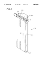
- FIG. 1 illustrates a perspective, exploded view of the oxygen tank mounting assembly of this invention, with the mounting assembly shown in the disassembled position;
- FIG. 1a shows a back perspective view of the base plate of the oxygen tank mounting assembly depicted in FIG. 1;
- FIG. 1b depicts a front, perspective view of the base plate of the oxygen tank mounting assembly depicted in FIG. 1;
- FIG. 1c shows a back perspective view of the mating tank mounting bracket plate of the oxygen tank mounting assembly depicted in FIG. 1;
- FIG. 1d depicts a front perspective view of the mating tank mounting bracket plate of the oxygen tank mounting assembly depicted in FIG. 1;
- FIG. 2 depicts a perspective view of the mounting assembly illustrated in FIG. 1, as shown in the assembled position;
- FIG. 2a is a sectional view of the mounting assembly shown in FIG. 2, wherein the protuberances are T-shaped;
- FIG. 2b is a sectional view of the mounting assembly shown in FIG. 2, wherein the protuberance are L-shaped;
- FIG. 3 shows an alternate embodiment of the mounting assembly illustrated in FIG. 1, with the oxygen tank mounting bracket designed for mounting two oxygen tanks;
- FIG. 4 illustrates a mounting assembly similar to that depicted in FIG. 1, that is used for mounting pony bottles.
- the invention features a mounting assembly for oxygen tanks and other vessels.
- the mounting assembly provides a quick assembly and disassembly of the oxygen tanks to a support harness or other body adaptor.
- FIG. 1 a perspective, exploded view of the oxygen tank mounting assembly 10 of this invention is illustrated.
- the mounting assembly 10 is shown disassembled.
- the mounting assembly 10 comprises two mating parts: a base plate 11 and an oxygen tank mounting bracket 12.
- the base plate 11 is shown in more detail with reference to FIGS. 1a and 1b, which depict the base plate 11 in respective back and front perspective views.
- the oxygen tank mounting bracket 12 is illustrated in more detail with reference to FIGS. 1c and 1d, which show the mounting bracket 12 in a back and front perspective view, respectively.
- Mounting bracket 12 has an outer curved surface 24 that conforms to the cylindrical shape of an oxygen tank (not shown). The oxygen tank rests upon surface 24, and then straps to the mounting bracket 12 by flexible, nylon bands (not shown) that girdle the mounting bracket 12 through spaces 19.
- the base plate 11 is shown having a number of spaced-apart protuberances 14, disposed along side edges 15.
- the protuberances 14 act as a key that fits the spaced-apart, T-shaped apertures 16 disposed along the edges 17 of the oxygen tank mounting bracket 12, as shown in FIGS. 1, 1c and 1d.
- the base plate 11 is interconnected with the mounting bracket 12 by moving the protuberances 14 into the spaces 19 disposed between the abutments 20 comprising the T-shaped apertures 16, as shown by arrows 18.
- the protuberances 14 are first positioned over the T-shaped openings 16, and then the base plate 11 is moved downwardly (arrow 22), so that the protuberances 14 enter and slide into the openings 16, similar to a key entering the passageway of a lock.
- the protuberances 14 are captured in the T-shaped openings 16, such that base plate 11 cannot now separate from the mounting bracket 12.
- Limiting abutments 26 stop the lowest protuberance 14 of base plate 11 from moving past the mounting bracket 12. Once located at its final resting position, the two interconnecting pieces 11 and 12 are secured by detent pins 28, which are placed into alignment holes 29.
- FIGS. 2a and 2b there are shown sectional views of the mounting assembly of the invention.
- protuberance 14 and receiving aperture 16 are T-shaped.
- FIG. 2b depicts an alternate embodiment of the inventive mounting assembly wherein protuberance 14' and corresponding aperture 16' are L-shaped.
- FIG. 3 an alternate embodiment 30 of the mounting assembly illustrated in FIG. 1 is shown.
- the oxygen tank mounting bracket 12a is designed for mounting two oxygen tanks, as depicted by the two curved surfaces 24a and 24b, respectively.
- the mounting assembly 40 comprises shortened plates 11b and 12b, respectively, and is used for mounting pony bottles (not shown).
- Surface 24bb is positioned over an oxygen tank cylinder.
- Surface 24aa conforms to, and accommodates the pony bottle. Strapping is used to attach the pony bottle to the tank.
Abstract
A quickly assembled and disassembled mounting bracket assembly for cylindrical objects, such as pressurized gas (e.g., oxygen) tanks, is described. The bracket assembly has two interconnecting parts: a bracket section and a base plate. The bracket section is slidable within the base plate, similar to a rail system. The two interconnecting pieces slidably interlock via spaced-apart T-shaped connectors disposed on distal side portions thereof. Assembly movement is minimal so that the two pieces can be joined quickly. Limiting stops provide mating alignment. Once in the aligned position, one or more locking detent pins are inserted through alignment holes disposed in the mating sections to secure the two parts in place.
Description
This invention relates to mounting brackets and, more particularly, to a rapid mounting assembly featuring a pair of interconnecting mounting brackets for accommodating curved or flat objects.
Scuba diving is a very popular activity. One of the time consuming inconveniences of getting prepared for a scuba dive is mounting the oxygen tanks to the harness worn about the torso of the diver. The oxygen cylinders are fairly heavy and bulky, thus making the mounting procedure particularly cumbersome and difficult. Oxygen cylinders are also worn by fire fighters and rescue personnel working in hazardous locations.
Presently, a very common way of securing these tanks to the harness is by tightening a band that is attached to the harness. The band girdles the circumference of the cylinder. Multiple oxygen cylinders are typically held together with a banding assembly which provides proper alignment of the cylinders relative to the valve manifold. The banding assembly is commonly attached to the harness via bolts passing through the cylinder bands.
Adjusting the above mounting apparatus is often very time consuming, because once the belting is loosened, the alignment must be reconfigured. Precise adjustment is necessary because nylon webbing, that can loosen when wet, creates the potential for the primary cylinder to slip from the harness during a dive.
Accordingly, it would be very useful to be able to quickly mount and remove the heavy and bulky oxygen tanks or other cylinders from a support harness.
The present invention introduces a quickly assembled and disassembled mounting bracket system for oxygen tanks. The two interconnecting parts comprise a bracket section and a mounting plate section. The bracket section is slidable within the mounting plate base, similar to a rail system. The two interconnecting pieces slidably interlock via spaced-apart T-section connectors. Movement during assembly is minimal. The two pieces are quickly joined. Limiting stops provide mating alignment. Once in the aligned position, two locking detent pins are inserted through alignment holes disposed in the mating sections to secure the two parts in place.
The mounting assembly, while most usefully employed for oxygen tanks, can also be used to mount similar items, such as pony bottles.
In U.S. Pat. No. 5,390,886, issued to Lawner et al, on Feb. 21, 1995, for SCUBA ACCESSORY INTERCHANGE SYSTEM, a quick disconnect device is shown for slidably interconnecting a female bracket attached to one scuba tank, with a male bracket. The interconnection is secured in place by means of a detent pin, similar to the present invention. The problem with the Lawner et al design is that the locking feature is totally dependent upon the detent pin. Should this detent pin shear, the mounting pieces are, unfortunately, free to disassemble.
By contrast, the present invention uses a plurality of interlocking T-sections for securing the two mating parts. The T-sections act as frictional guides that join the two sections in mating assembly. The internal stops provide accurate alignment of the mating parts. The two locking detent pins on each side of the bracket assembly provide redundant locking of the mating sections.
In accordance with the present invention, there is provided a quickly assembled and disassembled mounting bracket system for oxygen tanks. The bracket system comprises two interconnecting parts, a bracket section and a base plate. The bracket section is slidable within the base plate, similar to a rail system. The two interconnecting pieces slidably interlock via spaced-apart T-shaped connectors disposed on distal side portions thereof. Assembly movement is minimal, so that the two pieces can be joined quickly. Limiting stops provide mating alignment. Once in the aligned position, two locking detent pins are inserted through alignment holes disposed in the mating sections to secure the two parts in place.
It is an object of this invention to provide an improved mounting assembly for pressurized gas (e.g., oxygen) tanks.
It is another object of the invention to provide a quickly assembled and disassembled mounting system for oxygen tanks.
A complete understanding of the present invention may be obtained by reference to the accompanying drawings, when considered in conjunction with the subsequent detailed description, in which:
FIG. 1 illustrates a perspective, exploded view of the oxygen tank mounting assembly of this invention, with the mounting assembly shown in the disassembled position;
FIG. 1a shows a back perspective view of the base plate of the oxygen tank mounting assembly depicted in FIG. 1;
FIG. 1b depicts a front, perspective view of the base plate of the oxygen tank mounting assembly depicted in FIG. 1;
FIG. 1c shows a back perspective view of the mating tank mounting bracket plate of the oxygen tank mounting assembly depicted in FIG. 1;
FIG. 1d depicts a front perspective view of the mating tank mounting bracket plate of the oxygen tank mounting assembly depicted in FIG. 1;
FIG. 2 depicts a perspective view of the mounting assembly illustrated in FIG. 1, as shown in the assembled position;
FIG. 2a is a sectional view of the mounting assembly shown in FIG. 2, wherein the protuberances are T-shaped;
FIG. 2b is a sectional view of the mounting assembly shown in FIG. 2, wherein the protuberance are L-shaped;
FIG. 3 shows an alternate embodiment of the mounting assembly illustrated in FIG. 1, with the oxygen tank mounting bracket designed for mounting two oxygen tanks; and
FIG. 4 illustrates a mounting assembly similar to that depicted in FIG. 1, that is used for mounting pony bottles.
For purposes of brevity and clarity, like elements and components will bear the same designation and numbering throughout the figures.
Generally speaking, the invention features a mounting assembly for oxygen tanks and other vessels. The mounting assembly provides a quick assembly and disassembly of the oxygen tanks to a support harness or other body adaptor.
Now referring to FIG. 1, a perspective, exploded view of the oxygen tank mounting assembly 10 of this invention is illustrated. The mounting assembly 10 is shown disassembled. The mounting assembly 10 comprises two mating parts: a base plate 11 and an oxygen tank mounting bracket 12. The base plate 11 is shown in more detail with reference to FIGS. 1a and 1b, which depict the base plate 11 in respective back and front perspective views. The oxygen tank mounting bracket 12 is illustrated in more detail with reference to FIGS. 1c and 1d, which show the mounting bracket 12 in a back and front perspective view, respectively. Mounting bracket 12 has an outer curved surface 24 that conforms to the cylindrical shape of an oxygen tank (not shown). The oxygen tank rests upon surface 24, and then straps to the mounting bracket 12 by flexible, nylon bands (not shown) that girdle the mounting bracket 12 through spaces 19.
Now referring to FIGS. 1a and 1b, the base plate 11 is shown having a number of spaced-apart protuberances 14, disposed along side edges 15. The protuberances 14 act as a key that fits the spaced-apart, T-shaped apertures 16 disposed along the edges 17 of the oxygen tank mounting bracket 12, as shown in FIGS. 1, 1c and 1d.
Referring again to FIG. 1, the base plate 11 is interconnected with the mounting bracket 12 by moving the protuberances 14 into the spaces 19 disposed between the abutments 20 comprising the T-shaped apertures 16, as shown by arrows 18. The protuberances 14 are first positioned over the T-shaped openings 16, and then the base plate 11 is moved downwardly (arrow 22), so that the protuberances 14 enter and slide into the openings 16, similar to a key entering the passageway of a lock. The protuberances 14 are captured in the T-shaped openings 16, such that base plate 11 cannot now separate from the mounting bracket 12. The assembled condition is shown in FIG. 2. Limiting abutments 26 stop the lowest protuberance 14 of base plate 11 from moving past the mounting bracket 12. Once located at its final resting position, the two interconnecting pieces 11 and 12 are secured by detent pins 28, which are placed into alignment holes 29.
Referring now to FIGS. 2a and 2b, there are shown sectional views of the mounting assembly of the invention. In FIG. 2a, protuberance 14 and receiving aperture 16 are T-shaped. FIG. 2b depicts an alternate embodiment of the inventive mounting assembly wherein protuberance 14' and corresponding aperture 16' are L-shaped.
Referring to FIG. 3, an alternate embodiment 30 of the mounting assembly illustrated in FIG. 1 is shown. In this embodiment, the oxygen tank mounting bracket 12a is designed for mounting two oxygen tanks, as depicted by the two curved surfaces 24a and 24b, respectively.
Referring to FIG. 4, a mounting assembly 40 similar to that depicted in FIG. 1 is illustrated. The mounting assembly 40 comprises shortened plates 11b and 12b, respectively, and is used for mounting pony bottles (not shown). Surface 24bb is positioned over an oxygen tank cylinder. Surface 24aa conforms to, and accommodates the pony bottle. Strapping is used to attach the pony bottle to the tank.
Since other modifications and changes varied to fit particular operating requirements and environments will be apparent to those skilled in the art, the invention is not considered limited to the example chosen for purposes of disclosure, and covers all changes and modifications which do not constitute departures from the true spirit and scope of this invention.
Having thus described the invention, what is desired to be protected by Letters Patent is presented in the subsequently appended claims.
Claims (11)
1. A quickly assembled and disassembled mounting bracket system for mounting and dismounting an oxygen tank thereto, and therefrom, comprising:
a) a bracket assembly having a number of spaced-apart abutments with spaces between each pair of juxtaposed abutments, said abutments having means defining apertures therein, said apertures extending in a longitudinal direction with a lateral opening therealong and being further defined by an engaging surface;
b) a base plate that inter-engages with said bracket assembly, said base plate having a number of spaced-apart protuberances that conform to said engaging surface of said apertures and are received in said apertures of the abutments of said bracket assembly, said bracket assembly abutments being insertable in a lateral direction within said spaces of said base plate, and then longitudinally moved to a predetermined, fixed position wherein said protuberances are secured within said apertures to prevent the separation of said bracket assembly from said base plate in said lateral direction; and
c) securing means associated with said bracket assembly for preventing movement in said longitudinal direction, whereby said bracket assembly is secured from further movement relative to said base plate, whereby a quick release of said bracket assembly from said base plate is executed by removing said securing means and sliding said bracket assembly to a position wherein said protuberances are positioned opposite said spaces and said bracket assembly is removed from said base plate in a lateral direction.
2. The mounting bracket system for mounting and dismounting an oxygen tank in accordance with claim 1, wherein said engaging surface of said apertures of said abutments has a T-shape.
3. The mounting bracket system for mounting and dismounting an oxygen tank in accordance with claim 1, wherein said engaging surface of said apertures of said abutments has an L-shape.
4. The mounting bracket system for mounting and dismounting an oxygen tank in accordance with claim 1, wherein said securing means associated with said bracket assembly comprises a detent pin, and further wherein one of said abutments has an aperture for receiving said detent pin, said detent pin being insertable in said aperture, whereby said bracket assembly is prevented from movement with respect to said base plate.
5. The mounting bracket system for mounting and dismounting an oxygen tank in accordance with claim 1, wherein said mounting bracket assembly comprises an arcuate surface, said arcuate surface comprising a portion of a cylindrical surface conforming to said oxygen tank.
6. The mounting bracket system for mounting and dismounting an oxygen tank in accordance with claim 1, wherein said arcuate surface comprises means for supporting a pony bottle.
7. A quickly assembled and disassembled mounting bracket system for mounting and dismounting an pony bottle thereto and therefrom, comprising:
a) a bracket assembly having a number of spaced-apart abutments with spaces between each pair of juxtaposed abutments, said abutments having means defining apertures therein, said apertures extending in a longitudinal direction with a lateral opening therealong and being further defined by an engaging surface;
b) a base plate that inter-engages with said bracket assembly, said base plate having a number of spaced-apart protuberances that conform to said engaging surface of said apertures and are received in said apertures of the abutments of said bracket assembly, said bracket assembly abutments being insertable in a lateral direction within said spaces of said base plate, and then longitudinally moved to a predetermined, fixed position wherein said protuberances are secured within said apertures to prevent the separation of said bracket assembly from said base plate in said lateral direction; and
c) securing means associated with said bracket assembly for preventing movement in said longitudinal direction, whereby said bracket assembly is secured from further movement relative to said base plate, whereby a quick release of said bracket assembly from said base plate is executed by removing said securing means and sliding said bracket assembly to a position wherein said protuberances are positioned opposite said spaces and said bracket assembly is removed from said base plate in a lateral direction.
8. The mounting bracket system for mounting and dismounting a pony bottle in accordance with claim 7, wherein said engaging surface of said apertures of said abutments has a T-shape.
9. The mounting bracket system for mounting and dismounting a pony bottle in accordance with claim 7, wherein said engaging surface of said apertures of said abutments has an L-shape.
10. The mounting bracket system for mounting and dismounting a pony bottle in accordance with claim 7, wherein said securing means associated with said bracket assembly comprises a detent pin, and further wherein one of said abutments has an aperture for receiving said detent pin, said detent pin being insertable in said aperture, whereby said bracket assembly is prevented from movement with respect to said base plate.
11. The mounting bracket system for mounting and dismounting a pony bottle in accordance with claim 7, wherein said mounting bracket assembly comprises an arcuate surface, said arcuate surface comprising a portion of a cylindrical surface conforming to said pony bottle.
Priority Applications (1)
| Application Number | Priority Date | Filing Date | Title |
|---|---|---|---|
| US08/888,810 US5887836A (en) | 1997-07-07 | 1997-07-07 | Mounting bracket assembly |
Applications Claiming Priority (1)
| Application Number | Priority Date | Filing Date | Title |
|---|---|---|---|
| US08/888,810 US5887836A (en) | 1997-07-07 | 1997-07-07 | Mounting bracket assembly |
Publications (1)
| Publication Number | Publication Date |
|---|---|
| US5887836A true US5887836A (en) | 1999-03-30 |
Family
ID=25393956
Family Applications (1)
| Application Number | Title | Priority Date | Filing Date |
|---|---|---|---|
| US08/888,810 Expired - Lifetime US5887836A (en) | 1997-07-07 | 1997-07-07 | Mounting bracket assembly |
Country Status (1)
| Country | Link |
|---|---|
| US (1) | US5887836A (en) |
Cited By (20)
| Publication number | Priority date | Publication date | Assignee | Title |
|---|---|---|---|---|
| US6349908B1 (en) * | 1999-02-17 | 2002-02-26 | Eagle Electric Manufacturing Co., Inc. | Standoff assembly and method for supporting an electrical component |
| US6378825B1 (en) | 1999-12-29 | 2002-04-30 | General Electric Company | Control and power terminal block quick insert/disconnect |
| US6543736B2 (en) | 2001-01-16 | 2003-04-08 | Pacific Safety Products Inc. | Quick release supporting apparatus for a canister |
| US20040108429A1 (en) * | 2001-01-16 | 2004-06-10 | Field Bradley J. | Quick release supporting apparatus for a canister |
| US20050133526A1 (en) * | 2003-12-23 | 2005-06-23 | Lewis Richard P. | Mounting structure for viscous liquid dispenser |
| US20050269470A1 (en) * | 2004-06-02 | 2005-12-08 | North South Machine Shop, Inc. | Release bracket system and method |
| US20060054396A1 (en) * | 2004-08-11 | 2006-03-16 | Stringer Matthew D | Scaffold having a replaceable locking and securing device |
| US7406964B2 (en) * | 2005-09-08 | 2008-08-05 | Diaz Vincent P | SCUBA walk improved underwater breathing apparatus |
| US20100051567A1 (en) * | 2006-08-14 | 2010-03-04 | Component Concepts International, Llc | Container Mounting Assembly |
| US20110057009A1 (en) * | 2009-09-06 | 2011-03-10 | Mcleod Thomas | Dive valve quick release connector |
| WO2014033251A1 (en) * | 2012-08-31 | 2014-03-06 | Ees-Autogas Technologiezentrum Ug | Device for arranging gas containers in a trailer |
| US8740172B2 (en) * | 2010-07-02 | 2014-06-03 | Michael Essrig | Anti-tipover and seismic securement system |
| US20150144674A1 (en) * | 2013-11-27 | 2015-05-28 | Mine Safety Appliances Company | Modular tank cradle and backpack for self-contained breathing apparatus |
| US20180102074A1 (en) * | 2014-01-08 | 2018-04-12 | Calvin R. Peters | Adjustable bracket assembly for tensioning a pole mounted flag/banner and method of forming same |
| US10569108B2 (en) * | 2017-06-27 | 2020-02-25 | Draeger Safety Uk Limited | Harness for breathing apparatus |
| US10920928B2 (en) * | 2017-09-27 | 2021-02-16 | Globe (jiangsu) Co., Ltd. | Adjustable carrier assembly for a harness |
| US10932547B2 (en) * | 2017-09-27 | 2021-03-02 | Globe (jiangsu) Co., Ltd. | Carrier assembly for a harness |
| US11293585B2 (en) * | 2018-05-09 | 2022-04-05 | Hefei Boe Display Lighting Co., Ltd. | Pedestal, complete machine device and method for assembling the same |
| US20220120375A1 (en) * | 2021-04-26 | 2022-04-21 | Antonia Holder | Self-Standing Tablet Case with Expandable Legs and Collapsible Base |
| US11320088B1 (en) * | 2020-12-07 | 2022-05-03 | Ubtech North America Research And Development Center Corp | Display stand with height adjustment and tilt adjustment |
Citations (6)
| Publication number | Priority date | Publication date | Assignee | Title |
|---|---|---|---|---|
| US3902932A (en) * | 1973-10-16 | 1975-09-02 | Ronald C Gdanski | Holder for flexible sided container |
| US4030788A (en) * | 1975-10-28 | 1977-06-21 | Westinghouse Electric Corporation | Non-exposed drawer lock |
| US4190306A (en) * | 1977-04-06 | 1980-02-26 | L. B. (Plastics) Limited | Drawer with stop device |
| US4460141A (en) * | 1981-10-06 | 1984-07-17 | Elajo Invest Aktiebolag | Self-locking support clamp for mounting items on a support bar |
| US4889306A (en) * | 1988-09-20 | 1989-12-26 | Boucher Robert C | Scuba tank mounting bracket |
| US5390886A (en) * | 1991-02-15 | 1995-02-21 | Lawner; Irwin | Scuba accessory interchange system |
-
1997
- 1997-07-07 US US08/888,810 patent/US5887836A/en not_active Expired - Lifetime
Patent Citations (6)
| Publication number | Priority date | Publication date | Assignee | Title |
|---|---|---|---|---|
| US3902932A (en) * | 1973-10-16 | 1975-09-02 | Ronald C Gdanski | Holder for flexible sided container |
| US4030788A (en) * | 1975-10-28 | 1977-06-21 | Westinghouse Electric Corporation | Non-exposed drawer lock |
| US4190306A (en) * | 1977-04-06 | 1980-02-26 | L. B. (Plastics) Limited | Drawer with stop device |
| US4460141A (en) * | 1981-10-06 | 1984-07-17 | Elajo Invest Aktiebolag | Self-locking support clamp for mounting items on a support bar |
| US4889306A (en) * | 1988-09-20 | 1989-12-26 | Boucher Robert C | Scuba tank mounting bracket |
| US5390886A (en) * | 1991-02-15 | 1995-02-21 | Lawner; Irwin | Scuba accessory interchange system |
Cited By (30)
| Publication number | Priority date | Publication date | Assignee | Title |
|---|---|---|---|---|
| US6349908B1 (en) * | 1999-02-17 | 2002-02-26 | Eagle Electric Manufacturing Co., Inc. | Standoff assembly and method for supporting an electrical component |
| US6378825B1 (en) | 1999-12-29 | 2002-04-30 | General Electric Company | Control and power terminal block quick insert/disconnect |
| US6543736B2 (en) | 2001-01-16 | 2003-04-08 | Pacific Safety Products Inc. | Quick release supporting apparatus for a canister |
| US20040108429A1 (en) * | 2001-01-16 | 2004-06-10 | Field Bradley J. | Quick release supporting apparatus for a canister |
| US6830226B2 (en) * | 2001-01-16 | 2004-12-14 | Pacific Safety Products Inc. | Quick release supporting apparatus for a canister |
| US20050133526A1 (en) * | 2003-12-23 | 2005-06-23 | Lewis Richard P. | Mounting structure for viscous liquid dispenser |
| US20050269470A1 (en) * | 2004-06-02 | 2005-12-08 | North South Machine Shop, Inc. | Release bracket system and method |
| US7344116B2 (en) * | 2004-06-02 | 2008-03-18 | North South Machine Shop, Inc. | Release bracket system and method |
| US20060054396A1 (en) * | 2004-08-11 | 2006-03-16 | Stringer Matthew D | Scaffold having a replaceable locking and securing device |
| US7228940B2 (en) * | 2004-08-11 | 2007-06-12 | Bil-Jax, Inc. | Scaffold having a replaceable locking and securing device |
| US7406964B2 (en) * | 2005-09-08 | 2008-08-05 | Diaz Vincent P | SCUBA walk improved underwater breathing apparatus |
| US20100051567A1 (en) * | 2006-08-14 | 2010-03-04 | Component Concepts International, Llc | Container Mounting Assembly |
| US20110057009A1 (en) * | 2009-09-06 | 2011-03-10 | Mcleod Thomas | Dive valve quick release connector |
| US8740172B2 (en) * | 2010-07-02 | 2014-06-03 | Michael Essrig | Anti-tipover and seismic securement system |
| WO2014033251A1 (en) * | 2012-08-31 | 2014-03-06 | Ees-Autogas Technologiezentrum Ug | Device for arranging gas containers in a trailer |
| CN105764574B (en) * | 2013-11-27 | 2019-10-01 | Msa技术有限公司 | Modularization tank support and knapsack for self-contained breathing apparatus |
| US20150144674A1 (en) * | 2013-11-27 | 2015-05-28 | Mine Safety Appliances Company | Modular tank cradle and backpack for self-contained breathing apparatus |
| CN105764574A (en) * | 2013-11-27 | 2016-07-13 | Msa技术有限公司 | Modular tank cradle and backpack for self-contained breathing apparatus |
| EP3074095A1 (en) * | 2013-11-27 | 2016-10-05 | MSA Technology, LLC | Modular tank cradle and backpack for self-contained breathing apparatus |
| US9586065B2 (en) * | 2013-11-27 | 2017-03-07 | Msa Technology, Llc | Modular tank cradle and backpack for self-contained breathing apparatus |
| US10885816B2 (en) * | 2014-01-08 | 2021-01-05 | Cp Global, Llc | Adjustable bracket assembly for tensioning a pole mounted flag/banner and method of forming same |
| US20180102074A1 (en) * | 2014-01-08 | 2018-04-12 | Calvin R. Peters | Adjustable bracket assembly for tensioning a pole mounted flag/banner and method of forming same |
| US10569108B2 (en) * | 2017-06-27 | 2020-02-25 | Draeger Safety Uk Limited | Harness for breathing apparatus |
| US10994159B2 (en) | 2017-06-27 | 2021-05-04 | Draeger Safety Uk Limited | Harness for breathing apparatus |
| US10920928B2 (en) * | 2017-09-27 | 2021-02-16 | Globe (jiangsu) Co., Ltd. | Adjustable carrier assembly for a harness |
| US10932547B2 (en) * | 2017-09-27 | 2021-03-02 | Globe (jiangsu) Co., Ltd. | Carrier assembly for a harness |
| US11293585B2 (en) * | 2018-05-09 | 2022-04-05 | Hefei Boe Display Lighting Co., Ltd. | Pedestal, complete machine device and method for assembling the same |
| US11320088B1 (en) * | 2020-12-07 | 2022-05-03 | Ubtech North America Research And Development Center Corp | Display stand with height adjustment and tilt adjustment |
| US20220120375A1 (en) * | 2021-04-26 | 2022-04-21 | Antonia Holder | Self-Standing Tablet Case with Expandable Legs and Collapsible Base |
| US11629813B2 (en) * | 2021-04-26 | 2023-04-18 | Antonia Holder | Self-standing tablet case with expandable legs and collapsible base |
Similar Documents
| Publication | Publication Date | Title |
|---|---|---|
| US5887836A (en) | Mounting bracket assembly | |
| CA1133965A (en) | Fluid-conveying coupling with safety locking device | |
| US7350277B1 (en) | Buckle for safety equipment | |
| US4949889A (en) | Bracket for mounting auxiliary compressed air tank to a main tank | |
| EP2248555B1 (en) | Gas-cylinder retaining assembly | |
| US5271387A (en) | Harness connector for scuba tanks and the like | |
| EP0925091B1 (en) | Guarded snap hook | |
| US9889911B1 (en) | Back pack cinch | |
| US3367000A (en) | Detachable fastening device | |
| US10952509B2 (en) | Secure fit quick release belt system and method for use | |
| EP0570009B1 (en) | Backpack harness and cinch ring | |
| GB1394625A (en) | Tensioning and fastener device for tensioning straps or bands | |
| US20060175492A1 (en) | Mounting system | |
| US6478112B2 (en) | Rail mounted fall arrest assembly | |
| US6889390B1 (en) | Face mask retaining system | |
| US6155524A (en) | Quick release locking system | |
| US6367753B1 (en) | Pony tank quick release | |
| US4527816A (en) | Safety coupling arrangement | |
| US6354399B1 (en) | Sliding rail anchor fall-arrest system | |
| EP0756880B1 (en) | Improvements in or relating to breathing apparatus | |
| US20210261299A1 (en) | Cylinder-retaining apparatus for a breathing apparatus | |
| US4034416A (en) | Diving helmet breech ring connection | |
| EP0147451B1 (en) | Release mechanism | |
| EP4258935A1 (en) | Harness with quick-release mechanism | |
| EP2248554A1 (en) | Two-part structural support member for a harness for breathing apparatus |
Legal Events
| Date | Code | Title | Description |
|---|---|---|---|
| STCF | Information on status: patent grant |
Free format text: PATENTED CASE |
|
| FPAY | Fee payment |
Year of fee payment: 4 |
|
| FPAY | Fee payment |
Year of fee payment: 8 |
|
| FPAY | Fee payment |
Year of fee payment: 12 |
|
| SULP | Surcharge for late payment |
Year of fee payment: 11 |