US5895622A - Method and apparatus for composite manufacture - Google Patents
Method and apparatus for composite manufacture Download PDFInfo
- Publication number
- US5895622A US5895622A US08/833,595 US83359597A US5895622A US 5895622 A US5895622 A US 5895622A US 83359597 A US83359597 A US 83359597A US 5895622 A US5895622 A US 5895622A
- Authority
- US
- United States
- Prior art keywords
- tow
- particles
- electrode
- resin particles
- pair
- Prior art date
- Legal status (The legal status is an assumption and is not a legal conclusion. Google has not performed a legal analysis and makes no representation as to the accuracy of the status listed.)
- Expired - Fee Related
Links
Images


Classifications
-
- D—TEXTILES; PAPER
- D06—TREATMENT OF TEXTILES OR THE LIKE; LAUNDERING; FLEXIBLE MATERIALS NOT OTHERWISE PROVIDED FOR
- D06M—TREATMENT, NOT PROVIDED FOR ELSEWHERE IN CLASS D06, OF FIBRES, THREADS, YARNS, FABRICS, FEATHERS OR FIBROUS GOODS MADE FROM SUCH MATERIALS
- D06M15/00—Treating fibres, threads, yarns, fabrics, or fibrous goods made from such materials, with macromolecular compounds; Such treatment combined with mechanical treatment
- D06M15/70—Treating fibres, threads, yarns, fabrics, or fibrous goods made from such materials, with macromolecular compounds; Such treatment combined with mechanical treatment combined with mechanical treatment
- D06M15/705—Embossing; Calendering; Pressing
-
- B—PERFORMING OPERATIONS; TRANSPORTING
- B05—SPRAYING OR ATOMISING IN GENERAL; APPLYING FLUENT MATERIALS TO SURFACES, IN GENERAL
- B05D—PROCESSES FOR APPLYING FLUENT MATERIALS TO SURFACES, IN GENERAL
- B05D1/00—Processes for applying liquids or other fluent materials
- B05D1/02—Processes for applying liquids or other fluent materials performed by spraying
- B05D1/04—Processes for applying liquids or other fluent materials performed by spraying involving the use of an electrostatic field
- B05D1/045—Processes for applying liquids or other fluent materials performed by spraying involving the use of an electrostatic field on non-conductive substrates
-
- B—PERFORMING OPERATIONS; TRANSPORTING
- B05—SPRAYING OR ATOMISING IN GENERAL; APPLYING FLUENT MATERIALS TO SURFACES, IN GENERAL
- B05D—PROCESSES FOR APPLYING FLUENT MATERIALS TO SURFACES, IN GENERAL
- B05D7/00—Processes, other than flocking, specially adapted for applying liquids or other fluent materials to particular surfaces or for applying particular liquids or other fluent materials
- B05D7/20—Processes, other than flocking, specially adapted for applying liquids or other fluent materials to particular surfaces or for applying particular liquids or other fluent materials to wires
-
- B—PERFORMING OPERATIONS; TRANSPORTING
- B29—WORKING OF PLASTICS; WORKING OF SUBSTANCES IN A PLASTIC STATE IN GENERAL
- B29B—PREPARATION OR PRETREATMENT OF THE MATERIAL TO BE SHAPED; MAKING GRANULES OR PREFORMS; RECOVERY OF PLASTICS OR OTHER CONSTITUENTS OF WASTE MATERIAL CONTAINING PLASTICS
- B29B15/00—Pretreatment of the material to be shaped, not covered by groups B29B7/00 - B29B13/00
- B29B15/08—Pretreatment of the material to be shaped, not covered by groups B29B7/00 - B29B13/00 of reinforcements or fillers
- B29B15/10—Coating or impregnating independently of the moulding or shaping step
- B29B15/12—Coating or impregnating independently of the moulding or shaping step of reinforcements of indefinite length
-
- B—PERFORMING OPERATIONS; TRANSPORTING
- B29—WORKING OF PLASTICS; WORKING OF SUBSTANCES IN A PLASTIC STATE IN GENERAL
- B29C—SHAPING OR JOINING OF PLASTICS; SHAPING OF MATERIAL IN A PLASTIC STATE, NOT OTHERWISE PROVIDED FOR; AFTER-TREATMENT OF THE SHAPED PRODUCTS, e.g. REPAIRING
- B29C70/00—Shaping composites, i.e. plastics material comprising reinforcements, fillers or preformed parts, e.g. inserts
- B29C70/04—Shaping composites, i.e. plastics material comprising reinforcements, fillers or preformed parts, e.g. inserts comprising reinforcements only, e.g. self-reinforcing plastics
- B29C70/28—Shaping operations therefor
- B29C70/40—Shaping or impregnating by compression not applied
- B29C70/50—Shaping or impregnating by compression not applied for producing articles of indefinite length, e.g. prepregs, sheet moulding compounds [SMC] or cross moulding compounds [XMC]
-
- B—PERFORMING OPERATIONS; TRANSPORTING
- B29—WORKING OF PLASTICS; WORKING OF SUBSTANCES IN A PLASTIC STATE IN GENERAL
- B29C—SHAPING OR JOINING OF PLASTICS; SHAPING OF MATERIAL IN A PLASTIC STATE, NOT OTHERWISE PROVIDED FOR; AFTER-TREATMENT OF THE SHAPED PRODUCTS, e.g. REPAIRING
- B29C71/00—After-treatment of articles without altering their shape; Apparatus therefor
- B29C71/0081—After-treatment of articles without altering their shape; Apparatus therefor using an electric field, e.g. for electrostatic charging
-
- D—TEXTILES; PAPER
- D02—YARNS; MECHANICAL FINISHING OF YARNS OR ROPES; WARPING OR BEAMING
- D02J—FINISHING OR DRESSING OF FILAMENTS, YARNS, THREADS, CORDS, ROPES OR THE LIKE
- D02J1/00—Modifying the structure or properties resulting from a particular structure; Modifying, retaining, or restoring the physical form or cross-sectional shape, e.g. by use of dies or squeeze rollers
- D02J1/18—Separating or spreading
-
- D—TEXTILES; PAPER
- D06—TREATMENT OF TEXTILES OR THE LIKE; LAUNDERING; FLEXIBLE MATERIALS NOT OTHERWISE PROVIDED FOR
- D06M—TREATMENT, NOT PROVIDED FOR ELSEWHERE IN CLASS D06, OF FIBRES, THREADS, YARNS, FABRICS, FEATHERS OR FIBROUS GOODS MADE FROM SUCH MATERIALS
- D06M10/00—Physical treatment of fibres, threads, yarns, fabrics, or fibrous goods made from such materials, e.g. ultrasonic, corona discharge, irradiation, electric currents, or magnetic fields; Physical treatment combined with treatment with chemical compounds or elements
- D06M10/02—Physical treatment of fibres, threads, yarns, fabrics, or fibrous goods made from such materials, e.g. ultrasonic, corona discharge, irradiation, electric currents, or magnetic fields; Physical treatment combined with treatment with chemical compounds or elements ultrasonic or sonic; Corona discharge
- D06M10/025—Corona discharge or low temperature plasma
-
- D—TEXTILES; PAPER
- D06—TREATMENT OF TEXTILES OR THE LIKE; LAUNDERING; FLEXIBLE MATERIALS NOT OTHERWISE PROVIDED FOR
- D06M—TREATMENT, NOT PROVIDED FOR ELSEWHERE IN CLASS D06, OF FIBRES, THREADS, YARNS, FABRICS, FEATHERS OR FIBROUS GOODS MADE FROM SUCH MATERIALS
- D06M23/00—Treatment of fibres, threads, yarns, fabrics or fibrous goods made from such materials, characterised by the process
- D06M23/08—Processes in which the treating agent is applied in powder or granular form
-
- B—PERFORMING OPERATIONS; TRANSPORTING
- B29—WORKING OF PLASTICS; WORKING OF SUBSTANCES IN A PLASTIC STATE IN GENERAL
- B29C—SHAPING OR JOINING OF PLASTICS; SHAPING OF MATERIAL IN A PLASTIC STATE, NOT OTHERWISE PROVIDED FOR; AFTER-TREATMENT OF THE SHAPED PRODUCTS, e.g. REPAIRING
- B29C37/00—Component parts, details, accessories or auxiliary operations, not covered by group B29C33/00 or B29C35/00
- B29C2037/90—Measuring, controlling or regulating
-
- Y—GENERAL TAGGING OF NEW TECHNOLOGICAL DEVELOPMENTS; GENERAL TAGGING OF CROSS-SECTIONAL TECHNOLOGIES SPANNING OVER SEVERAL SECTIONS OF THE IPC; TECHNICAL SUBJECTS COVERED BY FORMER USPC CROSS-REFERENCE ART COLLECTIONS [XRACs] AND DIGESTS
- Y10—TECHNICAL SUBJECTS COVERED BY FORMER USPC
- Y10T—TECHNICAL SUBJECTS COVERED BY FORMER US CLASSIFICATION
- Y10T156/00—Adhesive bonding and miscellaneous chemical manufacture
- Y10T156/10—Methods of surface bonding and/or assembly therefor
- Y10T156/1052—Methods of surface bonding and/or assembly therefor with cutting, punching, tearing or severing
-
- Y—GENERAL TAGGING OF NEW TECHNOLOGICAL DEVELOPMENTS; GENERAL TAGGING OF CROSS-SECTIONAL TECHNOLOGIES SPANNING OVER SEVERAL SECTIONS OF THE IPC; TECHNICAL SUBJECTS COVERED BY FORMER USPC CROSS-REFERENCE ART COLLECTIONS [XRACs] AND DIGESTS
- Y10—TECHNICAL SUBJECTS COVERED BY FORMER USPC
- Y10T—TECHNICAL SUBJECTS COVERED BY FORMER US CLASSIFICATION
- Y10T156/00—Adhesive bonding and miscellaneous chemical manufacture
- Y10T156/12—Surface bonding means and/or assembly means with cutting, punching, piercing, severing or tearing
Definitions
- the present invention relates to a method and system for the production of resin coated fibers.
- Fiber-reinforced resin composites have gained an increasing market share for high performance parts used in various industries, as for example automotive and aircraft components.
- such composites are formed from a "prepreg” that includes carbon or glass fibers impregnated with a polymeric resin.
- the impregnated fibers are wound or layered against rigid mold surfaces and cured into structural parts.
- the fibers are woven or braided to enhance various properties of the composite.
- a “towpreg” is one type of composite prepreg which is formed by impregnating long continuous bundles of reinforcing fibers called “tows.” Tows of carbon or glass filaments are commercially available and may vary widely in the number of filaments per tow. Many matrix resins are also available; however, two kinds of matrix resin systems are of particular interest: thermoset and thermoplastic polymers.
- thermoset resin usually reacts in the presence of heat or a catalyst to produce a 3-dimensional structure that cannot be reshaped.
- Epoxies and certain polyimides are examples of thermosetting resins used in composite technology.
- thermoset materials have a relatively low viscosity during fiber impregnation.
- thermoplastic materials often have a significantly higher viscosity, typically 10 3 -10 7 times greater than thermoset resins. This relatively higher viscosity makes fiber impregnation with thermoplastic resins more difficult compared to typical thermoset resins.
- a thermoplastic resin retains its two-dimensional structure in the presence of heat and pressure. As a result, thermoplastic resins can be softened or melted many times, thus allowing for reshaping.
- PEKK Poly(aryl) ether ketone ketone
- PEEK Polyether-etherketone
- UHMWPE ultra high molecular weight polyethylene
- thermoplastic matrix composites are drawing increased interest, in part due to their excellent toughness, impact and chemical resistance, and potential for shorter processing times when compared with their thermoset counterparts.
- the high melt viscosities of thermoplastic polymers hinder the uniform impregnation of the composite fiber with resin during component manufacture.
- cost-effective processes must be developed that rapidly and uniformly impregnate fibers with resin and permit greater control over resin content.
- Fiber towpregs can be produced by a number of impregnation methods including hot melt, solution, emulsion, slurry, surface polymerization, fiber commingling, film interleaving, and dry powder techniques.
- dry powder processing is emerging as an attractive method for achieving a low-cost manufacturing process. Dry powder processes deposit polymeric resin particles directly on the fibers and then fix the powder particles onto the fibers to form a towpreg.
- the significant advantages of dry powder techniques are the elimination of solvents, the reduction in stress on the fibers, and the improved reclamation of unused resin powder. Avoidance of solvents and recovery of unused powder reduces environmental hazards and provides significant economic advantages as well.
- Various dry powder processes are described in U.S. Pat. Nos.
- One dry powder process for impregnating glass or carbon fibers uses a spray gun to direct polymer powder particles entrained in an airstream onto a continuous fiber tow. Prior to discharge from the gun, the powder is directed past a point source corona field to electrostatically charge the particles. After charging, the particle laden airstream is expelled through a nozzle at a relatively high rate of speed. Generally, the powder mass flow rate from the spray system needs to be high to propel particles over a significant area of the tow. As the expelled particles near the surface of the tow, an electrostatic attraction between the charged particles and the tow causes some of the particles to adhere to the tow fibers.
- the present invention relates to manufacture of a towpreg.
- Various aspects of the invention are novel, non-obvious, and provide various advantages. While the actual nature of the invention covered herein can only be determined with reference to the claims appended hereto, certain features which are characteristic of the preferred embodiment disclosed herein can be described briefly.
- One feature of the present invention is a technique of generating an electric field to control deposition of charged resin particles on a tow. This feature may include disposing an electrode across a portion of the tow to generate the field therealong. Deposition control may be generally decoupled from pneumatic particle delivery influences by orienting the electrode in accordance with the present invention.
- a further feature of the present invention is a composite manufacturing technique that includes moving a tow of long continuous fibers through a processing space and discharging a pressurized fluid stream entrained with a number of resin particles into the processing space through an orifice.
- the stream diverges from the orifice to distribute the particles in the processing space.
- At least a portion of the particles received in the processing space are electrostatically charged with a wire electrode positioned in the processing space.
- the resin particles are deposited on the tow and fixed thereto.
- the electrode generates a cylindrically shaped corona charging region which may be oriented relative to the tow and orifice to control particle deposition.
- a composite manufacturing technique includes electrostatically depositing a number of resin particles on a tow having a number of long continuous fibers and heating the tow to form a molten resin matrix from the particles.
- the tow is pulled between a pair of surfaces with at least one of the surfaces engaging the tow under a spring bias to controllably compress the tow and matrix between the surfaces.
- the spring bias is adjustable and may be regulated by a processor coupled to an associated actuator. Multiple impregnation stages each having a pair of tow compressing surfaces may be used to distribute a molten resin matrix among fibers of a tow.
- Another object of the present invention is to electrostatically charge resin particles along the length of an electrode.
- This electrode may include a wire configured to provide a generally cylindrical corona charging region.
- Another object is to separate the delivery nozzle creating the powder distribution from the charge location at the electrode.
- Yet another object is to provide a faster, less expensive way to controllably and adjustably impregnate tow fibers with a resin.
- FIG. 1 is a partially diagrammatic side view of a composite manufacturing system of a first preferred embodiment of the present invention.
- FIG. 2 is a partially diagrammatic top view of a portion of the system shown in the embodiment of FIG. 1.
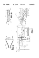
- FIG. 3 is a partially diagrammatic side view of a second preferred embodiment of the present invention.
- FIG. 3a is a partial sectional view taken along the section line 3a--3a shown in FIG. 3.
- FIG. 3b is a partial sectional view taken along section line 3b--3b of FIG. 3.
- FIG. 3b has a view plane that is generally perpendicular to the view plane of FIG. 3a.
- FIG. 4 is a partially diagrammatic side view of a composite manufacturing system of a third preferred embodiment of the present invention.
- FIG. 5a is a partially diagrammatic top view of a fourth preferred embodiment of the present invention.
- FIG. 5b is a partially diagrammatic top view of a fifth preferred embodiment of the present invention.
- FIG. 6 is a partially diagrammatic side view of a sixth preferred embodiment of the present invention.
- FIG. 7 is a partial top view of the embodiment of FIG. 6.
- FIG. 8a is a partially diagrammatic side view of a seventh preferred embodiment of the present invention.
- FIG. 8b is a partial end view of the embodiment of FIG. 8a.
- FIGS. 1 and 2 depict a composite manufacturing system 10 of the present invention.
- System 10 includes transport 20 which conveys tow 12 comprised of long continuous fibers 14 along an axis of travel generally parallel to the view planes of FIGS. 1 and 2; and in the direction represented by arrow T.
- Transport 20 is configured to move tow 12 through processing chamber 60 to deposit resin particles thereon as represented by arrows 16 in FIG. 1.
- Transport 20 includes a source spool 22 from which tow 12 is obtained.
- the tow passes through a tensioning system 24 having rollers 24a, 24b, and 24c.
- Tow 12 next encounters guide roller 26 and centering pulley 28.
- tow 12 is exposed to nitrogen gas heater 30.
- Heater 30 softens any polymer binder which may be present on the tow and the nitrogen gas often helps to reduce or prevent degradation of sizing on tow 12.
- the sizing helps molten resin particles adhere to the fibers.
- the gas flow also may help to separate tow 12 into individual filaments.
- sprayer 32 mists tow 12 with a conductive liquid to promote electrical conductivity along the tow.
- a conductive liquid to promote electrical conductivity along the tow.
- a fine water mist is used.
- the water also helps prevent fiber breakage and aids smooth, consistent spreading during later stages. Furthermore, the water is helpful in promoting the adherence of particles deposited on tow 12.
- transport 20 moves tow 12 into contact with grounding pulley 34 to further guide tow 12 and maintain tow 12 at generally the same electric potential as pulley 34.
- tow 12 contacts spherical spreader 36.
- tow 12 is spread mechanically by spreader 36 between 4 and 6 times its original width.
- centering pulley 28 and grounding pulley 34 positions tow 12 laterally and constrains it to pass over a smooth spherical surface of spreader 36.
- the existing fiber tension pulls the filament against both the curved leading and trailing edges of spreader 36.
- Each individual fiber of tow 12 will seek the shortest path across spreader 36, causing fibers 14 of tow 12 to spread over the sloped surface. After spreader 36, tow 12 is generally thinner with fibers 14 being generally distributed along a plane. A number of factors help determine final spreading width including fiber tension, spreader 36 dimensions, spreader 36 position relative to grounding pulley 34, tow preheat, and amount of water added.
- roller 46 guides tow 12 into processing chamber 60 through inlet 60a.
- Chamber 60 defines processing space 62 and includes roller 48 to further guide tow 12 therethrough.
- Chamber 60 is coupled to particle source 64 which provides airborne resin particles through conduit 66 for subsequent deposition on tow 12 in space 62.
- resin particles enter space 62 in an uncharged state and at a low mass flow rate to avoid adversely impacting uniform deposition on tow 12.
- Chamber 60 is also coupled to conduit 68 which is configured to collect and return undeposited resin particles to particle source 64 for reuse.
- Chamber 60 and conduits 66 and 68 are diagrammed in cross-section in FIGS. 1 and 2.
- Chamber 60 also encloses electrode 50. Electrode 50 is coupled to chamber 60 by insulated connector 50a opposing insulated connector 50b. Electrode 50 has surface 51 electrically exposed to tow 12 to permit formation of an electric field therebetween. Electrode 50 has longitudinal axis L spanning across tow 12 generally perpendicular to arrow T. Electrode 50 is generally parallel to a plane containing fibers 14 of tow 12 in region 13. Voltage source 40 is coupled to electrode 50 to apply an electric potential relative to grounding pulley 34.
- Voltage source 40 and electrode 50 are configured to electrostatically charge resin particles close to surface 51 of electrode 50 by corona charging.
- surface 51 of electrode 50 is roughened in a known manner to facilitate efficient corona charging.
- the voltage range of voltage source 40 is a D.C. voltage of about -20 to -100 kilovolts.
- the D.C. voltage range is about -25 to -45 kilovolts.
- the D.C. voltage is about -30 kilovolts.
- a different voltage may be used.
- the elongate nature of electrode 50 provides a charging region having a substantially right circular cylindrical shape about axis L along charging length C. A cross-section of this field is represented by dashed circle 53 shown in FIG. 1. This region represents the volume about electrode 50 wherein particles have a relatively high probability of being electrostatically charged. For a given distance separating a particle from electrode 50, the charging probability is about the same. Thus, the charging probability does not substantially vary along C, but does vary with the distance of the particle from electrode 50. By spreading corona charging along charging length C of electrode 50, repulsion of like charged particles is generally reduced.
- the elongate cylindrical shape of the charging region facilitates analysis of corona charging and corresponding electric fields in rectangular coordinates, which is well suited to powder coating of a generally rectilinear portion of a tow.
- the charging region and non-uniform electric field emanating from spray gun systems is more difficult to optimally adjust relative to a generally flat, straight-edged tow.
- electrode 50 is a roughened corona wire having a charging length of at least one centimeter. More preferably, the charging length in a range of about 1 to 5 centimeters. Most preferably, the charging length is at least 10 centimeters.
- U.S. Pat. Nos. 5,295,039 to Nakajima et al. and 5,412,212 to Rushing provide additional general information concerning corona charging wires.
- Electric field lines 58 are shown to illustrate the generally uniform cross-section of the electric field generated between electrode 50 and tow 12 along axis L upon application of voltage from voltage source 40. This field is generally symmetric about axis L and a vertical plane intersecting axis L. The electric field is distributed along a corresponding distance across tow 12 in the vicinity of exposed region 13.
- tow 12 The expansive exposure of tow 12 to electrode 50 creates an electric field which may be used to direct charged resin particles between electrode 50 and tow 12 onto region 13 without requiring a relatively high powder mass flow rate.
- the uniformity of the electric field across region 13 and generally perpendicular to the travel axis facilitates a more uniform deposition of charged resin particles along the tow width.
- electrostatic forces are generally sufficient to overcome gravity and particle momentum, which results in a nearly uniform coating of resin particles around each separated fiber or fiber bundle of tow 12. This highly uniform coating provides a better quality composite.
- the properties of the electric field are a function of the shape and relative orientation of electrode 50 to tow 12. Consequently, distribution of resin particle coating may be controlled by adjusting the relative configuration of electrode 50 and tow 12 within space 62.
- the airstream pattern and electric field of a typical electrostatic spray gun system are tightly coupled, which generally constrains electric field manipulation and powder particle distribution.
- fixation unit 70 After exiting outlet 60b, transport 20 then moves coated tow 12a into fixation unit 70.
- fixation unit 70 is preferably a tunnel oven, which at least partially melts the deposited resin particles so that they strongly adhere to tow fibers 14. Coated tow 12a exits fixation unit 70 as towpreg 12b. Towpreg 12b is guided by roller 72 and then wound up on collection spool 80 for subsequent use in manufacturing structural composite parts.
- fixation unit 70 may apply a protective coating either with or without heating, or may alternatively utilize another means of fixation.
- FIG. 3 illustrates composite manufacturing system 110 of a second preferred embodiment of the present invention.
- This embodiment includes a grounding pulley 134 and spreader 136 configured to spread fibers 114 of tow 112 moving along an axis of travel generally parallel to the view plane of FIG. 3, as represented by arrow T.
- tow 112 is guided by roller 146 through inlet 160a of chamber 160 (depicted in cross-section). Fibers 114 entering processing space 162 of chamber 160 are guided downward by roller 148 adjacent discharge outlet 152 of conduit 166 (shown in cross-section).
- Particle source 164 provides an airstream entrained with resin particles. This airstream travels through conduit 166 to divergent plenum 167. Plenum 167 has outlet 152 which intersects space 162 of chamber 160. Unused particles are returned to particle source 164 via conduit 168 (shown in cross-section).
- this embodiment has electrode 150 spanning across outlet 152 of plenum 167.
- Outlet 152 has width W and height H.
- Electrode 150 is coupled to plenum 167 by opposing insulated connections 150a and 150b. The airstream is discharged into divergent plenum 167 from conduit 166 through discharge orifice 167a. The particle laden airstream diverges as it departs orifice 167a. The divergent airstream then encounters electrode 150.
- Voltage source 140 is coupled to electrode 150 and grounding pulley 132 to provide an electric potential to electrode 150 relative to tow 112 to facilitate corona charging.
- Electrode 150 is configured to charge particles along its length as they emerge from plenum 167 and generates an electric field proximate to exposed area 113 of tow 112 to direct deposition of the charged resin particles.
- the divergent arrangement of plenum 167 presents a stream of particles 116 traveling with a reduced mass flow rate, which is approximately linearly distributed along electrode 150 for corona charging.
- width W of outlet 152 is about 7.5 inches and height H is about 1 inch to take advantage of better charging from close confines.
- This embodiment also has a pressure of about 2-8 psi through outlet 152 and includes a roughened nichrome corona wire of about 0.010 inch in diameter for electrode 150.
- PEKK resin particles with about a 50 micrometer particle size and a glass fiber tow are employed in this embodiment. It has been found for this embodiment that the rectangular confines of plenum 167, when suitably matched to the size of the charging region and shape of electrode 150, appear to provide more efficient charging of resin particles as compared to more expansive spaces.
- conduit 66 of system 10 includes a divergent plenum 67 arrangement to distribute particles in space 62 over electrode 50. The gradual divergence of the airstream through plenum 67 tends to reduce flow disturbances that may result from the abrupt discharge of the particle stream through a small orifice into a relatively large space.
- conduit and plenum arrangements are envisioned as would occur to those skilled in the art.
- coated tow 112a exits chamber 160 through outlet 160b for post-coating processing by a series of processing stations. From chamber 160, coated tow 112a enters melter or oven 170. Oven 170 is preferably a tunnel oven configured to at least partially melt deposited resin particles so that they remain fixed to tow fibers 114. The fiber/resin matrix exits oven 170 as towpreg 112b.
- Station 180 includes a base 181 connected to support posts 182.
- Posts 182 support top plate 183.
- base 181 and plate 183 generally have the same rectangular shape with the corners of one in registration with the corners of the other. Although only two posts 182 are shown, it is preferred that a support post be secured between base 181 and plate 183 in each corresponding pair of corners to provide a rigid and stable construct.
- Station 180 also includes a heated die 184 opposite adjustable plate 185.
- die 184 is a 500 watt electric rod heater with a digital temperature controller coupled thereteo.
- Die 184 heats a generally flat contact surface 184a.
- Plate 185 is configured to slide between base 181 and plate 183 via linear bearings 185a.
- Leaf spring 186 is connected to plate 185 at opposing ends with a smooth, arcuate shape. The shape of spring 186 is configured to guide towpreg 112b between surface 184a of die 184 and opposing surface 186a of spring 186.
- spring 186 is formed from a thin, metallic material which readily conducts heat.
- Rod 187 extends through opening 187a in plate 183 from a double-acting pneumatic cylinder 188 mounted on top of plate 183. Cylinder 188 is coupled to an appropriate pneumatic controller (not shown) to adjust the extension of rod 187 therefrom. Rod 187 slides through opening 187a to position plate 185 along posts 182 in response to activation of cylinder 188.
- towpreg 112b passes between surfaces 184a and 186a and is heated to form a molten resin matrix from the previously deposited particles.
- the thermally conductive structure of spring 186 is readily heated by die 184 to provide for uniform heating on both the top and bottom of tow 112b as it passes between surfaces 184a, 186a.
- cylinder 188 is adjusted to position plate 185 and corresponding bear against the top of towpreg 112b with spring 186.
- spring 186 is elastically deformed by this adjustment to provide a spring force to press towpreg 112b between surfaces 184a, 186a. Because surface 186a is under a spring bias, thickness variations in towpreg 112b tend to be smoothed out with a minimal risk of fiber damage.
- the nominal spring bias may be controlled and regulated by positioning plate 185 with cylinder 188.
- the degree of force and corresponding pressure exerted on towpreg 112b may be adjusted.
- impregnation may be readily optimized for the given configuration.
- station 180 facilitates adjustments to accommodate different fiber/resin configurations.
- the fixed cross-section die of other systems lack this flexibility, generally making optimization and configuration changes difficult and expensive.
- station 180 may be oriented relative to oven 170 so that oven 170 preheats coated towpreg 112b for further consolidation by station 180.
- Finishing unit 190 has opposing rollers 192, 194 to uniformly wind-up heated towpreg 112c about mandrel 196.
- a hot nitrogen gas torch 193 is used to maintain a high temperature at the point of consolidation to assist with formation of composite tube 118 from towpreg 112c. Additional torches, ovens, or other heaters may be employed as required for different sizes and resin/fiber combinations to preheat the tow to improve consolidation at finishing station 190.
- Composite tube 118 may then be used as a final component or further processed as would occur to one skilled in the art.
- FIG. 4 depicts a composite manufacturing system 210 of a third preferred embodiment of the present invention.
- tow 212 is directed under a grounding pulley 234 and spread by spreader 236.
- Tow 212 moves along an axis of travel generally parallel to the plans of view of FIG. 4, as represented by arrow T.
- Guide roller 246 guides tow 212 after spreading through inlet 260a of processing chamber 260 (shown in cross-section).
- Tow 212 exits chamber 260 through outlet 260b with the assistance of guide roller 248.
- Chamber 260 is coupled to particle source 264 which has conduit 266 (shown in cross-section) in fluid communication with chamber 260.
- Conduit 266 discharges airborne resin particles (indicated by arrows 216) into processing space 262 through orifice 267.
- Chamber 260 is also coupled to conduit 268 (shown in cross-section) to return undeposited resin particles to particle source 264 for reuse.
- elongate electrode 250 is disposed with a longitudinal axis L generally parallel to the axis of travel.
- electrode 250 is a roughened wire configured to electrostatically charge resin particles along a generally cylindrical corona charging region. A contour of this region is generally represented by dashed rectangle 253.
- Voltage source 240 is electrically coupled to electrode 250 and grounding pulley 234 to facilitate such corona charging.
- Tow 212 has an area 213 electrically exposed to surface 251 of electrode 250 to generate an electric field. The electric field resulting from the orientation of electrode 250 along the travel axis provides an alternative coating distribution which generally has a greater thickness at the middle of the tow.
- electrode 250 is separated from tow 212 by a first distance and orifice 267 is separated from tow 212 by a second distance.
- the second distance is greater than the first distance which corresponds with electrode 250 being between the tow 212 and the orifice 267.
- particles 216 are better dispersed in space 262 before charging when electrode 250 is positioned in this manner.
- the placement of orifice 267 farther away from tow 212 than electrode 250 reduces pneumatic disturbances to resin particles deposited on tow 212.
- electrode 350 for composite manufacturing in accordance with the present invention is depicted in chamber 360 (shown in cross-section).
- electrode 350 has a curvilinear, serpentine form and is fastened to chamber 360 by insulated connectors 350a, 350b.
- a voltage source 340 is coupled across electrode 350 and tow 312 to provide an electric potential relative to tow 312 to electrostatically charge resin particles in chamber 360.
- Tow 312 moves along an axis of travel parallel to the view plane as represented by arrow T.
- FIG. 5b shows still another alternative electrode 450 for composite manufacturing in accordance with the present invention.
- Electrode 450 is enclosed in chamber 460 (shown in cross-section) to deposit resin particles on tow 412 moving along an axis of travel parallel to the plane of view of FIG. 5b as represented by arrow T.
- Electrode 450 includes a number of elongate electrode segments 452, 454, 456. Each segment 452, 454, 456 traverses tow 412 at a non-perpendicular angle relative to arrow T. Furthermore, each segment 452, 454, 456 is coupled to chamber 460. Similar to previously described embodiments, electrode 450 is electrically coupled to a voltage source 440 to electrostatically charge resin particles and generate an electric field between electrode segments 452, 454, 456 and tow 412.
- a corresponding electric field may be tailored to direct charged resin particles.
- This electric field may be configured to control distribution so that resin particle deposition is greater or less in certain regions depending on the orientation of segments 452, 454, 456.
- System 510 includes a tow 512 with a number of elongate fibers which are dispensed from tension control station 520.
- Station 520 includes tow source spool 522 from which tow 512 is unwound.
- Tow 512 is pulled through system 510 along a travel axis in the direction indicated by arrow T using drive rollers in station 590 (not shown).
- Tow 512 engages pulleys 524a-524d which cooperate with spool 522 to maintain a generally constant tension.
- Pulley 524c is mounted on a load cell (not shown) which generates a tension signal corresponding to tension of tow 512.
- spool 522 is mounted on a shaft of a bidirectional motor which winds or unwinds tow 512 in accordance with the tension signal via a closed loop control system.
- This system may be configured to receive an input corresponding to the desired tension level.
- tension control station 520 is implemented with equipment from American Sahm. In other embodiments, a different tow dispensing arrangement may be employed as would occur to one skilled in the art.
- Station 530 includes outer shroud 531 with entrance slot 531a and exit slot 531b. Within shroud 531, tow 512 passes between plenum 532 and upper plate 533. In one embodiment plate 533 provides about a 0.010 inch gap from top surface 534 of plenum 532. Referring additionally to FIG. 7, a top cross-sectional view of station 530 is illustrated. Surface 534 defines a narrow, elongate slot 535 which is generally perpendicular to the direction of travel of tow 512. Conduit 536 is in fluid communication with the interior space of plenum 532 via coupling 537.
- pressurized air is controllably provided from controlled pressurized air supply 539 via conduit 536 for discharge through slot 535.
- Tow 512 travels between plate 533 and plenum 532, generally sliding along surface 534.
- the individual fibers tend to spread apart into a wider area to depart through exit slot 531b as spread tow 513.
- the air discharged through slot 535 exits through the gap between plate 533 and surface 534 of plenum 532.
- Spread tow 513 next encounters misting station 540.
- a conductive liquid mist from mister 542 is applied to the fibers of tow 513 to assure proper electrical conductivity.
- Mister 542 receives the conductive liquid from liquid source 544.
- Station 540 is placed in close proximity to station 530 to ground tow 513 through contact with plenum 532.
- Plenum 532 includes a conductive material suitable to provide grounding.
- shroud 531 and plate 533 are made from a generally transparent, polymeric resin based plastic compound and plenum 532 is made from aluminum.
- Misted tow 514 departs misting station 540 to travel to coating station 548.
- Station 548 includes electrode 550 coupled to voltage source 552.
- Electrode 550 is positioned within processing space 562 of chamber 560 with a longitudinal axis generally parallel to the direction of travel of tow 514. Misted tow 514 enters chamber 560 through entrance 560a.
- Particle supply system 564 is configured to provide a fluid stream entrained with particles to space 562.
- System 564 includes hopper 564a which holds resin particle powder for metering to space 562.
- Hopper 564a includes two agitator paddles (not shown) to feed powder to rotating metering screw 564b.
- Screw 564b has a hollow flight to meter powder at a selected rate to tube 564c. As screw 564b is rotated, powder travels to tube 564c.
- Rotary pneumatic vibrator 564d contacts tube 564c to fluidize the powder as it travels therethrough. The powder travels down tube 564c to venturi pump 565.
- tube 564c has a vertical drop of about 13 inches.
- Pump 565 has a narrowed neck region 565a in fluid communication with inlet conduit 565b through which pressurized air is provided from supply 539.
- Neck region 565a creates a low pressure zone which tends to draw powder from tube 564c into the airstream supplied from conduit 565b. The powder laden airstream then exits through conduit 566.
- Conduit 566 supplies the airstream to orifice 567a for discharge into space 562. Notably the airstream diverges as it enters space 562 to distribute powder along the length of electrode 550. Electrode 550 provides a generally cylindrical charging region with its longitudinal axis oriented generally along the length of the fibers of tow 514 to facilitate deposition of large amounts of resin powder. The path of the resin powder is generally designated by arrows 569. Unused powder is returned to system 564 from chamber 560 via conduit 568.
- Coated tow 515 departs chamber 560 through exit 560b and then encounters fixation station 570.
- Station 570 is configured to affix deposited resin powder to fibers of the tow to provide towpreg 516.
- Station 570 may provide fixation by at least partially melting the deposited powder or applying another fixation technique known to those skilled in the art.
- Towpreg 516 travels from station 570 to impregnation station 580.
- Station 580 improves impregnation of tow fibers by the resin which then departs as consolidated towpreg 517.
- Station 580 may be configured similar to station 180 of system 110 previously described.
- Towpreg 517 enters chopper station 590 from station 580.
- Station 590 includes a drive mechanism (not shown) to draw the tow fibers through system 510.
- This mechanism may include one or more frictional rollers or spindles which present the end portion of towpreg 517 to a chopping unit for cutting into a number of pieces or pellets 518. Pellets 518 are collected in bin 599.
- pellets 518 are preferably at least 1/8 of an inch long. In a more preferred embodiment, pellets 518 have a length in the range of 1/8 of an inch to 1 inch. In another more preferred embodiment, pellets 518 have a width of no more than 1/8 of an inch.
- Pellets 518 may be processed in a variety of ways. In one embodiment, pellets 518 collected in bin 599 are subsequently used in an injection molding processes. In another embodiment, pellets 518 are collected on a first endless belt instead of in bin 599 (not shown). This first endless belt carries pellets 518 to a second endless belt. The first and second belts rotate in opposite directions. Pellets 518 are received between the first and second rotating belts to be compression molded therebetween. This compression molding forms a composite sheet from pellets 518 for further processing as would occur to one skilled in the art.
- System 610 may serve as impregnation station 580 for system 510.
- System 610 includes tow 612 which is carrying a resin compound.
- Tow 612 is configured for movement in the direction indicated by arrow T.
- Tow 612 first encounters processing stage 620.
- Stage 620 includes base 622 and upper plate 624.
- Plate 624 is supported by two support posts 626 extending from base 622 (see FIG. 8b).
- Posts 626 are located on either side of adjustable plate 628 which is positioned between base 622 and plate 624.
- Plate 628 is configured to slide up and down along posts 626 via linear bearings 630.
- Stage 620 includes double acting pneumatic cylinder 632 mounted to plate 624.
- Cylinder 632 has rod 633 extending through aperture 624a in plate 624 and is configured to move in response to activation of cylinder 632.
- Rod 633 is connected to plate 628 to adjust position thereof.
- Plate 628 includes an arcuate leaf spring 634 connected thereto.
- Spring 634 has contact surface 636.
- Base 622 includes a heated die 638 configured to heat contact surface 640.
- surface 640 provides a generally flat expansive area with which to heat tow 612 and spring 634.
- Towpreg 612 is heated to melt associated resin and is pressed between surfaces 636, 640 to facilitate impregnation of the fibers of tow 612 by the molten resin.
- Cylinder 632 positions plate 628 to elastically deform spring 634 similar to the operation of station 180 for system 110 previously described.
- Heated die 638 may likewise be similar to die 184 of station 180.
- Stage 650 is configured with the same structural features as stage 620 which are indicated by like reference numerals.
- Cylinders 632 are coupled to pneumatic lines 621, 651 for stages 620 and 650, respectively.
- Lines 621, 651 are representative of the fluid conduits necessary to control the double action of cylinder 632 for each corresponding stage 620, 650.
- Lines 621, 651 are coupled to controller 660 via pneumatic control 662.
- Pneumatic control 662 is coupled to pressurized air supply 664 to selectively route pressurized air to lines 621, 651 in accordance with control signals from controller 660. These control signals correspond to a desired position of plate 628 to provide a selected impregnation pressure with spring 634 for each of stages 620, 650.
- the control signals may be generated by controller 660 in response to an input by an operator or automatically determined from monitoring other parameters of a composite manufacturing system.
- stage 620, 650 Between stages 620, 650 is drive mechanism 670 which pulls tow 612 in direction T.
- the tension imposed by pulling tow 612 through stages 620, 650 is generally additive, which may undesirably limit tow travel speed.
- Mechanism 670 reduces tension between stages 620, 650 by pulling on tow 612.
- a mechanism to drive or wind tow 612 downstream of stage 650 is also provided (not shown).
- the pressure against tow 612 provided by stage 620 is less than stage 650. Generally, this difference may be used to improve impregnation quality or increase travel speed of tow 612 for a give impregnation quality level as compared to a single stage system.
- the heating temperature provide by die 638 for each of stages 620, 650 may also differ to provide a selected heating rate of tow 612 as it passes through system 610. Controller 660 may be adapted to control each die 638 in addition to each cylinder 632. In other embodiments, the temperature and pressure of each stage may be about the same or otherwise controlled as would occur to one skilled in the art.
- additional spring/die stages may be employed and controlled by controller 660. It is envisioned that a large number of stages may be utilized in series to increase processing speed without substantially impacting quality. Also one or more of cylinders 632 may be replaced by another type of controllable linear actuator such as a hydraulic cylinder or electromagnetic device. Moreover, the impregnation techniques provided by the present invention may be applied to resin/fiber configurations obtained by techniques other than dry powder deposition.
- Controller 660 may be an electronic circuit comprised of one or more components including digital circuitry, analog circuitry, or both. Also, controller 660 may be programmable, an integrated state machine, or a hybrid combination thereof. Controller 660 may be adapted to control one or more of the stages, stations, or components previously described in connection with FIGS. 1-7.
- electrodes of the present invention may be used to provide a means for generating an electric field with a selected geometry to control particle deposition in a predetermined manner.
- the electrode be elongate and generally linear to facilitate modeling of desired parameters for dry polymer powder coating of a tow. This preferred embodiment may be achieved by employing a corona wire.
- electrodes or electrode segments for the present invention be elongate, with a length of at least about one centimeter. More preferably, the length is in the range of about 1 to 5 centimeters. Most preferably, the length is at least about 10 centimeters.
- the electrode of the present invention may be used to charge resin particles and simultaneously provide an electric field to direct deposition of the charged particles.
- at least one electrode is used to direct particles which have been independently charged by another source.
- the electrode is used principally to control the deposition of the charged particles.
- the electrode is used to direct charged particles supplied by a conventional spray gun operating at a high particle mass flow rate.
- the electrode may supplement an independent resin particle charger by charging only a portion of the particles.
- both systems 110 and 210 may include a heater similar to heater 30 of system 10 and a sprayer similar to sprayer 32.
- the embodiments of system 10 and 210 may be adapted to use an impregnation system similar to station 180 of system 110.
- particle sources may be provided as a fluidized bed similar to that disclosed in U.S. Pat. No. 5,302,419 to Muzzy. These examples are not intended to be limiting, but rather are illustrative of a few alternative implementations of the present invention.
- the fiber spreading technique used depends upon the type of fibers and associated packaging. Carbon fibers typically come in a single-ended package, without binding components to hold the fibers together. The individual fibers of the carbon tow are free to move relative to each other, aiding spreading.
- Fiberglass is commonly packaged in two different forms, single-ended and multi-ended tows.
- the single-ended tow is a common form for E-glass which has one bundle of fibers bound together by a chemical binder.
- Single-ended glass fiber tows are preferably treated in the manner disclosed in FIGS. 1 and 2.
- the multi-ended tow a packaging form for S-glass as well as E-glass, combines several small single-ended tows into a larger tow.
- a 12,000 strand S-glass tow might consist of 30 strands of 400 fibers each.
- the smaller tows comprising the entire strand are typically each coated with a binder.
- Spreading the smaller tows into individual fibers is generally undesirable so the heating stage to soften the binder is not ordinarily used. This modification reduces the chance of sizing damage that may cause a poor fiber-resin interface. It also may result in a less uniform distribution of resin among the fibers.
- some form of in-line rolling or pultrusion might be necessary for multi-ended glass fiber tows to achieve desired uniformity when used with a consolidation system.
- the chambers and shrouds described herein are preferably made from a material suitable for exposure to the associated fibers, resins, and electric fields.
- the chambers and shrouds are made from a durable, transparent material, such as a clear thermoplastic, to facilitate observation of the process taking place therein.
- Polymer classes suitable for resin powders used with the present invention may be of the thermoplastic or thermoset variety.
- suitable polymer classes include, but are not limited to: the ABS group, acetals, acrylics, alkyd polyesters, allyls, aminos, epoxies, fluoroplastics, furnace, melamines, nylons, phenolics, phenylene oxides and ethers, polyamidemides, polybutylenes, polycarbonates, polyesters, poly (aryl ether ketone ketone) (PEKK), polyetheretherketones (PEEK), polyetherimides, polyethylenes, polyamides, polymethylpentenes, polyphenylene sulfides, polypropylenes, polystyrenes, polyurethanes, sulfones, ureas and vinyls.
Landscapes
- Engineering & Computer Science (AREA)
- Textile Engineering (AREA)
- Mechanical Engineering (AREA)
- Physics & Mathematics (AREA)
- Plasma & Fusion (AREA)
- Chemical & Material Sciences (AREA)
- Composite Materials (AREA)
- Life Sciences & Earth Sciences (AREA)
- Wood Science & Technology (AREA)
- Chemical Or Physical Treatment Of Fibers (AREA)
Abstract
Description
Claims (58)
Priority Applications (1)
| Application Number | Priority Date | Filing Date | Title |
|---|---|---|---|
| US08/833,595 US5895622A (en) | 1997-04-07 | 1997-04-07 | Method and apparatus for composite manufacture |
Applications Claiming Priority (1)
| Application Number | Priority Date | Filing Date | Title |
|---|---|---|---|
| US08/833,595 US5895622A (en) | 1997-04-07 | 1997-04-07 | Method and apparatus for composite manufacture |
Publications (1)
| Publication Number | Publication Date |
|---|---|
| US5895622A true US5895622A (en) | 1999-04-20 |
Family
ID=25264829
Family Applications (1)
| Application Number | Title | Priority Date | Filing Date |
|---|---|---|---|
| US08/833,595 Expired - Fee Related US5895622A (en) | 1997-04-07 | 1997-04-07 | Method and apparatus for composite manufacture |
Country Status (1)
| Country | Link |
|---|---|
| US (1) | US5895622A (en) |
Cited By (36)
| Publication number | Priority date | Publication date | Assignee | Title |
|---|---|---|---|---|
| US20010043668A1 (en) * | 2000-05-10 | 2001-11-22 | Rigaku Corporation | Method and apparatus for measuring thin film, and thin film deposition system |
| LU90623B1 (en) * | 2000-08-04 | 2002-02-05 | Trefilarbed Bissen Sa | Method and installation for coating wire material |
| US20030178148A1 (en) * | 2002-03-19 | 2003-09-25 | Mccardell Edward | Spot laminator with charging bar |
| WO2003095386A1 (en) * | 2002-05-10 | 2003-11-20 | British Telecommunications Public Limited Company | Fibre coating method and apparatus |
| US20040231598A1 (en) * | 2001-09-16 | 2004-11-25 | Eran Werner | Electrostatic coater and method for forming prepregs therewith |
| US20050003082A1 (en) * | 2003-01-29 | 2005-01-06 | Roelofs Robert R. | Method of powder coating weldable substrates |
| EP1526214A1 (en) * | 2003-10-21 | 2005-04-27 | Materials Technics Holding Société Anonyme | Process and device for impreganting a fibre network with powder material in an electrostatic field with alternating current |
| US20050215148A1 (en) * | 2004-03-25 | 2005-09-29 | Pc Composites Ltd. | Pre-impregnated materials |
| US20050287891A1 (en) * | 2004-06-09 | 2005-12-29 | Park David B | Composite material of continuous fiber and ultra high molecular weight polyethylene |
| WO2006134271A1 (en) * | 2005-06-15 | 2006-12-21 | Saertex France | Method for making a reinforcement for composite material with variable resistance profile, resulting reinforcement |
| WO2008017882A1 (en) * | 2006-08-07 | 2008-02-14 | Airbus Uk Limited | Method op manufacturing composite material and apparatus therefore |
| US20090246468A1 (en) * | 2008-03-30 | 2009-10-01 | Iq Tec Switzerland Gmbh | Apparatus and method for making reactive polymer pre-pregs |
| US20090246737A1 (en) * | 2002-06-28 | 2009-10-01 | Scott Jacobs | Teeth treatment devise |
| US20110104364A1 (en) * | 2008-06-27 | 2011-05-05 | Buo Chen | High-Speed Pultrusion Process for the Manufacture of Fiber Reinforced Composites |
| US20110229698A1 (en) * | 2010-03-19 | 2011-09-22 | E2E Materials, Inc. | Biodegradable resin composites |
| CN102958657A (en) * | 2010-06-30 | 2013-03-06 | 东丽株式会社 | Process and apparatus for producing sheet-shaped prepreg |
| WO2013175183A2 (en) * | 2012-05-22 | 2013-11-28 | University Of Leeds | Process |
| US20160177475A1 (en) * | 2011-02-21 | 2016-06-23 | United States Council For Automotive Research, Llc | Fiber tow treatment apparatus and system |
| JP2016215559A (en) * | 2015-05-25 | 2016-12-22 | 株式会社 サン・テクトロ | Prepreg production method |
| CN106629254A (en) * | 2016-12-07 | 2017-05-10 | 周易 | Carbon fiber extension device and method |
| US20170268135A1 (en) * | 2016-03-21 | 2017-09-21 | Ford Global Technologies, Llc | Method of separating fiber tows |
| KR20170141231A (en) * | 2015-04-30 | 2017-12-22 | 에보니크 데구사 게엠베하 | METHOD AND DEVICE FOR PRODUCING FIBER COMPOSITE MATERIAL |
| US20180065300A1 (en) * | 2016-09-06 | 2018-03-08 | Cc3D Llc | Additive manufacturing system having in-head fiber teasing |
| US20180126643A1 (en) * | 2016-11-04 | 2018-05-10 | Cc3D Llc | Additive manufacturing system having movable anchor guide |
| CN108705788A (en) * | 2018-05-24 | 2018-10-26 | 金凌印刷(苏州)有限公司 | A kind of material surface processing unit |
| CN109137310A (en) * | 2018-10-29 | 2019-01-04 | 浙江康洁丝新材料科技有限公司 | A kind of tow medium spraying mechanism, method and multipurpose elasticizer |
| CN109358460A (en) * | 2018-12-05 | 2019-02-19 | 浙江大学昆山创新中心 | A kind of device of manufacturing cycle polarization domain reverse structure crystal |
| CN109375450A (en) * | 2018-12-05 | 2019-02-22 | 浙江大学昆山创新中心 | A kind of device and method of manufacturing cycle polarization domain reverse crystal |
| CN109407439A (en) * | 2018-12-05 | 2019-03-01 | 浙江大学昆山创新中心 | A kind of preparation facilities of novel cycle polarization domain reverse structure crystal |
| EP3459922A1 (en) * | 2017-09-25 | 2019-03-27 | United Technologies Corporation | Continuous multiple tow coating reactor |
| US20200114596A1 (en) * | 2018-10-12 | 2020-04-16 | Arris Composites Inc. | Preform Charges And Fixtures Therefor |
| EP3751032A1 (en) * | 2019-06-11 | 2020-12-16 | Corex Materials Corporation | Fabrics woven by spread tow yarns consisting of polymer matrix composite and method for producing the same |
| US11167454B2 (en) * | 2017-01-13 | 2021-11-09 | General Electric Company | Method and apparatus for continuously refreshing a recoater blade for additive manufacturing |
| US11186025B2 (en) * | 2017-02-23 | 2021-11-30 | Kraussmaffei Technologies Gmbh | Method and apparatus for producing fibre-reinforced plastic mouldings |
| US20220168971A1 (en) * | 2017-06-02 | 2022-06-02 | Arris Composites Llc | Aligned fiber reinforced molding |
| WO2022129781A1 (en) | 2020-12-17 | 2022-06-23 | Arkema France | Method for manufacturing a fibrous material which is made of continuous fibres and impregnated with a thermoplastic polymer |
Citations (18)
| Publication number | Priority date | Publication date | Assignee | Title |
|---|---|---|---|---|
| US3817211A (en) * | 1972-02-22 | 1974-06-18 | Owens Corning Fiberglass Corp | Apparatus for impregnating strands, webs, fabrics and the like |
| US4292105A (en) * | 1978-12-28 | 1981-09-29 | Union Carbide Corporation | Method of impregnating a fibrous textile material with a plastic resin |
| US4614678A (en) * | 1983-06-28 | 1986-09-30 | Atochem | Flexible composite material and process for producing same |
| US4714642A (en) * | 1983-08-30 | 1987-12-22 | Basf Aktiengesellschaft | Carbon fiber multifilamentary tow which is particularly suited for weaving and/or resin impregnation |
| US4765544A (en) * | 1986-01-16 | 1988-08-23 | Kopperschmidt-Mueller Gmbh & Co. Kg | Electrostatic spray gun |
| US4779564A (en) * | 1986-06-09 | 1988-10-25 | Morton Thiokol, Inc. | Apparatus for electrostatic powder spray coating and resulting coated product |
| US4839199A (en) * | 1985-07-16 | 1989-06-13 | Flexline Services Ltd. | Method and apparatus for applying powdered materials to filaments |
| US5057338A (en) * | 1990-05-16 | 1991-10-15 | The United States Of America As Represented By The Administrator Of The National Aeronautics And Space Administration | Process for application of powder particles to filamentary materials |
| US5094883A (en) * | 1989-04-17 | 1992-03-10 | Georgia Tech Research Corporation | Flexible multiply towpreg and method of production therefor |
| US5102690A (en) * | 1990-02-26 | 1992-04-07 | Board Of Trustees Operating Michigan State University | Method coating fibers with particles by fluidization in a gas |
| US5123373A (en) * | 1990-02-26 | 1992-06-23 | Board Of Trustees Operating Michigan State University | Method for fiber coating with particles |
| US5128199A (en) * | 1990-02-26 | 1992-07-07 | Board Of Trustees Operating Michigan State University | Method for fiber coating with particles |
| US5171630A (en) * | 1989-04-17 | 1992-12-15 | Georgia Tech Research Corporation | Flexible multiply towpreg |
| US5295039A (en) * | 1989-03-10 | 1994-03-15 | Fuji Photo Film Co., Ltd. | Method of applying single polar electro-static charges to continuously travelling long web support, and apparatus practicing same |
| US5302419A (en) * | 1989-04-17 | 1994-04-12 | Georgia Tech Research Corporation | Towpregs from recycled plastics by powder fusion coating and method of production therefor |
| US5337131A (en) * | 1992-11-12 | 1994-08-09 | Indigo N.V. | Charging apparatus operative to charge a surface |
| US5370911A (en) * | 1990-04-20 | 1994-12-06 | The University Of Akron | Method of depositing and fusing charged polymer particles on continuous filaments |
| US5412212A (en) * | 1993-12-06 | 1995-05-02 | Eastman Kodak Company | Corona-charging apparatus and method |
-
1997
- 1997-04-07 US US08/833,595 patent/US5895622A/en not_active Expired - Fee Related
Patent Citations (19)
| Publication number | Priority date | Publication date | Assignee | Title |
|---|---|---|---|---|
| US3817211A (en) * | 1972-02-22 | 1974-06-18 | Owens Corning Fiberglass Corp | Apparatus for impregnating strands, webs, fabrics and the like |
| US4292105A (en) * | 1978-12-28 | 1981-09-29 | Union Carbide Corporation | Method of impregnating a fibrous textile material with a plastic resin |
| US4614678A (en) * | 1983-06-28 | 1986-09-30 | Atochem | Flexible composite material and process for producing same |
| US4713139A (en) * | 1983-06-28 | 1987-12-15 | Atochem | Apparatus for producing flexible composite material |
| US4714642A (en) * | 1983-08-30 | 1987-12-22 | Basf Aktiengesellschaft | Carbon fiber multifilamentary tow which is particularly suited for weaving and/or resin impregnation |
| US4839199A (en) * | 1985-07-16 | 1989-06-13 | Flexline Services Ltd. | Method and apparatus for applying powdered materials to filaments |
| US4765544A (en) * | 1986-01-16 | 1988-08-23 | Kopperschmidt-Mueller Gmbh & Co. Kg | Electrostatic spray gun |
| US4779564A (en) * | 1986-06-09 | 1988-10-25 | Morton Thiokol, Inc. | Apparatus for electrostatic powder spray coating and resulting coated product |
| US5295039A (en) * | 1989-03-10 | 1994-03-15 | Fuji Photo Film Co., Ltd. | Method of applying single polar electro-static charges to continuously travelling long web support, and apparatus practicing same |
| US5302419A (en) * | 1989-04-17 | 1994-04-12 | Georgia Tech Research Corporation | Towpregs from recycled plastics by powder fusion coating and method of production therefor |
| US5094883A (en) * | 1989-04-17 | 1992-03-10 | Georgia Tech Research Corporation | Flexible multiply towpreg and method of production therefor |
| US5171630A (en) * | 1989-04-17 | 1992-12-15 | Georgia Tech Research Corporation | Flexible multiply towpreg |
| US5128199A (en) * | 1990-02-26 | 1992-07-07 | Board Of Trustees Operating Michigan State University | Method for fiber coating with particles |
| US5123373A (en) * | 1990-02-26 | 1992-06-23 | Board Of Trustees Operating Michigan State University | Method for fiber coating with particles |
| US5102690A (en) * | 1990-02-26 | 1992-04-07 | Board Of Trustees Operating Michigan State University | Method coating fibers with particles by fluidization in a gas |
| US5370911A (en) * | 1990-04-20 | 1994-12-06 | The University Of Akron | Method of depositing and fusing charged polymer particles on continuous filaments |
| US5057338A (en) * | 1990-05-16 | 1991-10-15 | The United States Of America As Represented By The Administrator Of The National Aeronautics And Space Administration | Process for application of powder particles to filamentary materials |
| US5337131A (en) * | 1992-11-12 | 1994-08-09 | Indigo N.V. | Charging apparatus operative to charge a surface |
| US5412212A (en) * | 1993-12-06 | 1995-05-02 | Eastman Kodak Company | Corona-charging apparatus and method |
Non-Patent Citations (18)
| Title |
|---|
| D.E. Woolard and K. Ramani, Electric Field Modeling for Electrostatic Powder Coating of a Continuous Fiber Bundle , Journal of Electrostatics, vol. 35, No. 4, pp. 373 385, (1995). * |
| D.E. Woolard and K. Ramani, Electric Field Modeling for Electrostatic Powder Coating of a Continuous Fiber Bundle, Journal of Electrostatics, vol. 35, No. 4, pp. 373-385, (1995). |
| Dr. K. Ramani and M. Bays, In situ Manufacture of Thermoplastic Composite Tubes , (date unknown). * |
| Dr. K. Ramani and M. Bays, In-situ Manufacture of Thermoplastic Composite Tubes, (date unknown). |
| Heated Tow Impregnation and Heated Die Close Up , Photographs, (1995). * |
| Heated Tow Impregnation and Heated Die Close Up, Photographs, (1995). |
| K. Ramani and F.F. Caillat, Manufacture of S 2 Glass/Polycarbonate Composites by Electrostatic Powder Spray Coating , (date unknown). * |
| K. Ramani and F.F. Caillat, Manufacture of S-2 Glass/Polycarbonate Composites by Electrostatic Powder Spray Coating, (date unknown). |
| Karen J. Fisher, Low Cost Thermoplastic Composites: On The Verge , Advanced Composites, pp. 30 36, (Jan./Feb. 1993). * |
| Karen J. Fisher, Low-Cost Thermoplastic Composites: On The Verge?, Advanced Composites, pp. 30-36, (Jan./Feb. 1993). |
| Karthik Ramani and Mark Duvall, In situ Composite Manufacture Using Electrostatic Powder Spray Processing and Filament Winding , Submitted to National Science Foundation under Grant No. PDM 9308498, (Jan. 1996). * |
| Karthik Ramani and Mark Duvall, In-situ Composite Manufacture Using Electrostatic Powder Spray Processing and Filament Winding, Submitted to National Science Foundation under Grant No. PDM-9308498, (Jan. 1996). |
| Karthik Ramani, Daniel E. Woolard, and Mark S. Duvall, An Electrostatic powder Spray Process for Manufacturing Thermoplastic Composites , Polymer Composites, vol. 16, Issue 6, pp. 459 469, (Dec. 1995). * |
| Karthik Ramani, Daniel E. Woolard, and Mark S. Duvall, An Electrostatic powder Spray Process for Manufacturing Thermoplastic Composites, Polymer Composites, vol. 16, Issue 6, pp. 459-469, (Dec. 1995). |
| Mark Duvall and Karthik Ramani, Application of an Electrostatic Spray Process to Filament Winding , American Society Mechanical Engineering Proceedings, (1995). * |
| Mark Duvall and Karthik Ramani, Application of an Electrostatic Spray Process to Filament Winding, American Society Mechanical Engineering Proceedings, (1995). |
| Mark Duvall and Karthik Ramani, In situ Composite Manfuacture using an Electrostatic Spray Process and Filament Winding , Proceedings, 10th Annual Int l Conference on Composite Materials, procedings, vol. 3, pp. 469 476, (Aug. 1995). * |
| Mark Duvall and Karthik Ramani, In-situ Composite Manfuacture using an Electrostatic Spray Process and Filament Winding, Proceedings, 10th Annual Int'l Conference on Composite Materials, procedings, vol. 3, pp. 469-476, (Aug. 1995). |
Cited By (80)
| Publication number | Priority date | Publication date | Assignee | Title |
|---|---|---|---|---|
| US20010043668A1 (en) * | 2000-05-10 | 2001-11-22 | Rigaku Corporation | Method and apparatus for measuring thin film, and thin film deposition system |
| US6970532B2 (en) * | 2000-05-10 | 2005-11-29 | Rigaku Corporation | Method and apparatus for measuring thin film, and thin film deposition system |
| WO2002011903A1 (en) * | 2000-08-04 | 2002-02-14 | Trefilarbed Bissen S.A. | Method and installation for coating wire material |
| LU90623B1 (en) * | 2000-08-04 | 2002-02-05 | Trefilarbed Bissen Sa | Method and installation for coating wire material |
| WO2003024609A3 (en) * | 2001-09-16 | 2014-11-20 | Pc Composites Ltd. | Electrostatic coater and method for forming prepregs therewith |
| US20040231598A1 (en) * | 2001-09-16 | 2004-11-25 | Eran Werner | Electrostatic coater and method for forming prepregs therewith |
| US20030178148A1 (en) * | 2002-03-19 | 2003-09-25 | Mccardell Edward | Spot laminator with charging bar |
| US6808593B2 (en) | 2002-03-19 | 2004-10-26 | Af Machine Inc. | Spot laminator with charging bar |
| CN1304316C (en) * | 2002-05-10 | 2007-03-14 | 英国电讯有限公司 | Fibre coating method and apparatus |
| US7618676B2 (en) | 2002-05-10 | 2009-11-17 | British Telecommunications Public Limited Company | Fibre coating method and apparatus |
| US20050153067A1 (en) * | 2002-05-10 | 2005-07-14 | Barker Philip A. | Fibre coating method and apparatus |
| US20070169692A1 (en) * | 2002-05-10 | 2007-07-26 | British Telecommunications Public Limited Company | Fibre coating method and apparatus |
| EP1785403A3 (en) * | 2002-05-10 | 2007-07-04 | British Telecommunications Public Limited Company | Fibre coating method and apparatus |
| WO2003095386A1 (en) * | 2002-05-10 | 2003-11-20 | British Telecommunications Public Limited Company | Fibre coating method and apparatus |
| EP1785403A2 (en) * | 2002-05-10 | 2007-05-16 | British Telecommunications Public Limited Company | Fibre coating method and apparatus |
| US7842340B2 (en) | 2002-05-10 | 2010-11-30 | British Telecommunications Plc | Fibre coating method and apparatus |
| US7849661B2 (en) * | 2002-06-28 | 2010-12-14 | Scott Jacobs | Teeth treatment device |
| US20090246737A1 (en) * | 2002-06-28 | 2009-10-01 | Scott Jacobs | Teeth treatment devise |
| US7618677B2 (en) * | 2003-01-29 | 2009-11-17 | Ppg Industries Ohio, Inc. | Method of powder coating weldable substrates |
| US20050003082A1 (en) * | 2003-01-29 | 2005-01-06 | Roelofs Robert R. | Method of powder coating weldable substrates |
| US20060233966A1 (en) * | 2003-10-21 | 2006-10-19 | Joric Marduel | Process for impregnating a fibrous, filamentary and/or porous network with powder using electrodes subjected to an AC electric field |
| WO2005038123A1 (en) * | 2003-10-21 | 2005-04-28 | Materials Technics Holding Sa | Method and device for impregnating a fibrous web with a powder using an alternating electrostatic field |
| US7534473B2 (en) | 2003-10-21 | 2009-05-19 | Materials Technics Holding S.A. | Process for impregnating a fibrous, filamentary and/or porous network with powder using electrodes subjected to an AC electric field |
| EP1526214A1 (en) * | 2003-10-21 | 2005-04-27 | Materials Technics Holding Société Anonyme | Process and device for impreganting a fibre network with powder material in an electrostatic field with alternating current |
| US20050215148A1 (en) * | 2004-03-25 | 2005-09-29 | Pc Composites Ltd. | Pre-impregnated materials |
| WO2005123999A3 (en) * | 2004-06-09 | 2006-11-09 | Phoenixx T P C Inc | A composite material of continuous fiber and ultra high molecular weight polyethylene |
| WO2005123999A2 (en) * | 2004-06-09 | 2005-12-29 | Phoenixx T.P.C., Incorporated | A composite material of continuous fiber and ultra high molecular weight polyethylene |
| US20050287891A1 (en) * | 2004-06-09 | 2005-12-29 | Park David B | Composite material of continuous fiber and ultra high molecular weight polyethylene |
| US8647456B2 (en) | 2005-06-15 | 2014-02-11 | Saertex France | Process for production of a reinforcement for composite material with a variable resistance profile, reinforcement obtained |
| US20080196820A1 (en) * | 2005-06-15 | 2008-08-21 | Saertex France | Process For Production Of A Reinforcement For Composite Material With A Variable Resistance Profile, Reinforcement Obtaine |
| FR2887265A1 (en) * | 2005-06-15 | 2006-12-22 | Saertex France Soc Par Actions | METHOD FOR MAKING A REINFORCEMENT FOR A COMPOSITE MATERIAL WITH A VARIABLE RESISTANCE PROFILE, REINFORCED REINFORCEMENT |
| WO2006134271A1 (en) * | 2005-06-15 | 2006-12-21 | Saertex France | Method for making a reinforcement for composite material with variable resistance profile, resulting reinforcement |
| CN101247940B (en) * | 2005-06-15 | 2012-08-01 | 法兰西塞特克斯 | Process for production of a reinforcement for composite material with a variable resistance profile, reinforcement obtained |
| US8420183B2 (en) | 2006-08-07 | 2013-04-16 | Airbus Operations Limited | Method of manufacturing composite material |
| WO2008017882A1 (en) * | 2006-08-07 | 2008-02-14 | Airbus Uk Limited | Method op manufacturing composite material and apparatus therefore |
| US20090297726A1 (en) * | 2006-08-07 | 2009-12-03 | Airbus Uk Limited | Method of manufacturing composite material |
| US8241711B2 (en) * | 2006-08-07 | 2012-08-14 | Airbus Operations Limited | Method of manufacturing composite material |
| US20100040857A1 (en) * | 2008-03-30 | 2010-02-18 | Iq Tec Switzerland Gmbh | Apparatus and method for making reactive polymer pre-pregs |
| JP2011516654A (en) * | 2008-03-30 | 2011-05-26 | アイキュー テック スウィツァランド ゲーエムベーハー | Apparatus and method for making a reactive polymer prepreg |
| US20090246468A1 (en) * | 2008-03-30 | 2009-10-01 | Iq Tec Switzerland Gmbh | Apparatus and method for making reactive polymer pre-pregs |
| WO2009122259A1 (en) * | 2008-03-30 | 2009-10-08 | Iq Tec Switzerland Gmbh | Apparatus and method for making reactive polymer pre-pregs |
| US20110104364A1 (en) * | 2008-06-27 | 2011-05-05 | Buo Chen | High-Speed Pultrusion Process for the Manufacture of Fiber Reinforced Composites |
| US20110229698A1 (en) * | 2010-03-19 | 2011-09-22 | E2E Materials, Inc. | Biodegradable resin composites |
| CN102958657A (en) * | 2010-06-30 | 2013-03-06 | 东丽株式会社 | Process and apparatus for producing sheet-shaped prepreg |
| KR101787143B1 (en) | 2010-06-30 | 2017-10-18 | 도레이 카부시키가이샤 | Process and apparatus for producing sheet-shaped prepreg |
| US10138579B2 (en) * | 2011-02-21 | 2018-11-27 | United States Council For Automotive Research, Llc | Fiber tow treatment apparatus and system |
| US20160177475A1 (en) * | 2011-02-21 | 2016-06-23 | United States Council For Automotive Research, Llc | Fiber tow treatment apparatus and system |
| WO2013175183A2 (en) * | 2012-05-22 | 2013-11-28 | University Of Leeds | Process |
| WO2013175183A3 (en) * | 2012-05-22 | 2014-03-20 | University Of Leeds | Process for preparing a thermoplastic prepreg |
| KR20170141231A (en) * | 2015-04-30 | 2017-12-22 | 에보니크 데구사 게엠베하 | METHOD AND DEVICE FOR PRODUCING FIBER COMPOSITE MATERIAL |
| US20180297239A1 (en) * | 2015-04-30 | 2018-10-18 | Evonik Degussa Gmbh | Process and device for the production of a fiber-composite material |
| US11618183B2 (en) * | 2015-04-30 | 2023-04-04 | Evonik Operations Gmbh | Process and device for the production of a fiber-composite material |
| JP2016215559A (en) * | 2015-05-25 | 2016-12-22 | 株式会社 サン・テクトロ | Prepreg production method |
| US20170268135A1 (en) * | 2016-03-21 | 2017-09-21 | Ford Global Technologies, Llc | Method of separating fiber tows |
| US10543640B2 (en) * | 2016-09-06 | 2020-01-28 | Continuous Composites Inc. | Additive manufacturing system having in-head fiber teasing |
| US20180065300A1 (en) * | 2016-09-06 | 2018-03-08 | Cc3D Llc | Additive manufacturing system having in-head fiber teasing |
| WO2018048805A1 (en) * | 2016-09-06 | 2018-03-15 | Cc3D Llc | Additive manufacturing system having in-head fiber teasing |
| US10994481B2 (en) | 2016-09-06 | 2021-05-04 | Continuous Composites Inc. | Additive manufacturing system having in-head fiber-teasing |
| US11000998B2 (en) | 2016-09-06 | 2021-05-11 | Continous Composites Inc. | Additive manufacturing system having in-head fiber-teasing |
| US20180126643A1 (en) * | 2016-11-04 | 2018-05-10 | Cc3D Llc | Additive manufacturing system having movable anchor guide |
| CN106629254A (en) * | 2016-12-07 | 2017-05-10 | 周易 | Carbon fiber extension device and method |
| US11801633B2 (en) | 2017-01-13 | 2023-10-31 | General Electric Company | Apparatuses for continuously refreshing a recoater blade for additive manufacturing including a blade feed unit and arm portion |
| US11167454B2 (en) * | 2017-01-13 | 2021-11-09 | General Electric Company | Method and apparatus for continuously refreshing a recoater blade for additive manufacturing |
| US11186025B2 (en) * | 2017-02-23 | 2021-11-30 | Kraussmaffei Technologies Gmbh | Method and apparatus for producing fibre-reinforced plastic mouldings |
| US20220168971A1 (en) * | 2017-06-02 | 2022-06-02 | Arris Composites Llc | Aligned fiber reinforced molding |
| US11633926B2 (en) | 2017-06-02 | 2023-04-25 | Arris Composites Inc. | Aligned fiber reinforced molding |
| US10941491B2 (en) | 2017-09-25 | 2021-03-09 | Raytheon Technologies Corporation | Continuous multiple tow coating reactor |
| EP3459922A1 (en) * | 2017-09-25 | 2019-03-27 | United Technologies Corporation | Continuous multiple tow coating reactor |
| US11697878B2 (en) | 2017-09-25 | 2023-07-11 | Raytheon Technologies Corporation | Continuous multiple tow coating reactor |
| CN108705788B (en) * | 2018-05-24 | 2020-05-05 | 金凌印刷(苏州)有限公司 | Material surface treatment device |
| CN108705788A (en) * | 2018-05-24 | 2018-10-26 | 金凌印刷(苏州)有限公司 | A kind of material surface processing unit |
| US20220203633A1 (en) * | 2018-10-12 | 2022-06-30 | Arris Composites Inc. | Preform Charges And Fixtures Therefor |
| US20200114596A1 (en) * | 2018-10-12 | 2020-04-16 | Arris Composites Inc. | Preform Charges And Fixtures Therefor |
| CN109137310A (en) * | 2018-10-29 | 2019-01-04 | 浙江康洁丝新材料科技有限公司 | A kind of tow medium spraying mechanism, method and multipurpose elasticizer |
| CN109358460A (en) * | 2018-12-05 | 2019-02-19 | 浙江大学昆山创新中心 | A kind of device of manufacturing cycle polarization domain reverse structure crystal |
| CN109375450A (en) * | 2018-12-05 | 2019-02-22 | 浙江大学昆山创新中心 | A kind of device and method of manufacturing cycle polarization domain reverse crystal |
| CN109407439A (en) * | 2018-12-05 | 2019-03-01 | 浙江大学昆山创新中心 | A kind of preparation facilities of novel cycle polarization domain reverse structure crystal |
| EP3751032A1 (en) * | 2019-06-11 | 2020-12-16 | Corex Materials Corporation | Fabrics woven by spread tow yarns consisting of polymer matrix composite and method for producing the same |
| FR3117913A1 (en) * | 2020-12-17 | 2022-06-24 | Arkema France | Process for manufacturing a fibrous material in continuous fibers impregnated with thermoplastic polymer |
| WO2022129781A1 (en) | 2020-12-17 | 2022-06-23 | Arkema France | Method for manufacturing a fibrous material which is made of continuous fibres and impregnated with a thermoplastic polymer |
Similar Documents
| Publication | Publication Date | Title |
|---|---|---|
| US5895622A (en) | Method and apparatus for composite manufacture | |
| US5409757A (en) | Flexible multiply towpreg tape from powder fusion coated towpreg | |
| US11518068B2 (en) | Strands powdered by electrostatic method | |
| US5094883A (en) | Flexible multiply towpreg and method of production therefor | |
| US5171630A (en) | Flexible multiply towpreg | |
| US5198281A (en) | Non-woven flexible multiply towpreg fabric | |
| EP0600106B1 (en) | Mat forming process and apparatus | |
| US5370911A (en) | Method of depositing and fusing charged polymer particles on continuous filaments | |
| RU2632298C2 (en) | Method for fibrous blank manufacturing | |
| US4626306A (en) | Process for manufacturing profiled strips in fiber-loaded thermoplastic resin, installation for the implementation thereof and profiled strips obtained | |
| US5302419A (en) | Towpregs from recycled plastics by powder fusion coating and method of production therefor | |
| NO130864B (en) | ||
| US5123373A (en) | Method for fiber coating with particles | |
| JP2017507045A (en) | Method for producing thermoplastic polymer pre-impregnated fiber material in a fluidized bed | |
| JPH02160907A (en) | Method and apparatus for manufacture | |
| US7547361B2 (en) | Method and apparatus for fabrication of polymer-coated fibers | |
| Goud et al. | Dry electrostatic spray coated towpregs for thermoplastic composites | |
| CN109641372B (en) | Method for treating fibres, apparatus for treating fibres and belt made of treated fibres thus obtained | |
| Ramani et al. | An electrostatic powder spray process for manufacturing thermoplastic composites | |
| RU2632300C2 (en) | Loading device for controlled stacking of beams of fitting fibers | |
| US5360661A (en) | Towpregs from recycled plastics by powder fusion coating | |
| WO2014170637A1 (en) | Method and apparatus for aligning discontinuous fibres | |
| WO1998031535A1 (en) | Method and apparatus for treating strands with pulverulent material | |
| WO1996022180A1 (en) | Fiber bundle coating apparatus and method | |
| Duvall et al. | In-situ composite manufacture using an electrostatic powder spray process and filament winding |
Legal Events
| Date | Code | Title | Description |
|---|---|---|---|
| AS | Assignment |
Owner name: PURDUE RESEARCH FOUNDATION, INDIANA Free format text: ASSIGNMENT OF ASSIGNORS INTEREST;ASSIGNOR:RAMANI, KARTHIK;REEL/FRAME:008527/0936 Effective date: 19970326 Owner name: PURDUE RESEARCH FOUNDATION, INDIANA Free format text: ASSIGNMENT OF ASSIGNORS INTEREST;ASSIGNOR:DUVALL, MARK STEPHEN;REEL/FRAME:008527/0967 Effective date: 19970326 Owner name: PURDUE RESEARCH FOUNDATION, INDIANA Free format text: ASSIGNMENT OF ASSIGNORS INTEREST;ASSIGNOR:WOOLARD, DANIEL EDWARD;REEL/FRAME:008527/0920 Effective date: 19970326 |
|
| FEPP | Fee payment procedure |
Free format text: PAT HOLDER CLAIMS SMALL ENTITY STATUS, ENTITY STATUS SET TO SMALL (ORIGINAL EVENT CODE: LTOS); ENTITY STATUS OF PATENT OWNER: SMALL ENTITY |
|
| FPAY | Fee payment |
Year of fee payment: 4 |
|
| REMI | Maintenance fee reminder mailed | ||
| REMI | Maintenance fee reminder mailed | ||
| LAPS | Lapse for failure to pay maintenance fees | ||
| LAPS | Lapse for failure to pay maintenance fees |
Free format text: PATENT EXPIRED FOR FAILURE TO PAY MAINTENANCE FEES (ORIGINAL EVENT CODE: EXP.); ENTITY STATUS OF PATENT OWNER: SMALL ENTITY |
|
| STCH | Information on status: patent discontinuation |
Free format text: PATENT EXPIRED DUE TO NONPAYMENT OF MAINTENANCE FEES UNDER 37 CFR 1.362 |
|
| FP | Lapsed due to failure to pay maintenance fee |
Effective date: 20070420 |