US5899239A - Tubular fencing components formed from plastic sheet material - Google Patents
Tubular fencing components formed from plastic sheet material Download PDFInfo
- Publication number
- US5899239A US5899239A US08/593,411 US59341196A US5899239A US 5899239 A US5899239 A US 5899239A US 59341196 A US59341196 A US 59341196A US 5899239 A US5899239 A US 5899239A
- Authority
- US
- United States
- Prior art keywords
- clip members
- tubular shape
- generally
- peripheral side
- portions
- Prior art date
- Legal status (The legal status is an assumption and is not a legal conclusion. Google has not performed a legal analysis and makes no representation as to the accuracy of the status listed.)
- Expired - Lifetime
Links
Images


Classifications
-
- E—FIXED CONSTRUCTIONS
- E04—BUILDING
- E04H—BUILDINGS OR LIKE STRUCTURES FOR PARTICULAR PURPOSES; SWIMMING OR SPLASH BATHS OR POOLS; MASTS; FENCING; TENTS OR CANOPIES, IN GENERAL
- E04H17/00—Fencing, e.g. fences, enclosures, corrals
- E04H17/14—Fences constructed of rigid elements, e.g. with additional wire fillings or with posts
- E04H17/20—Posts therefor
Definitions
- the present invention relates to plastic fencing components.
- the invention relates to elongated tubular plastic fencing components, e.g., posts, pickets and rails used in modular plastic fencing systems, and improved methods for manufacturing the same.
- Plastics present a desirable alternative to wood as a construction material for fencing, particularly in terms of ease of use and durability.
- modular vinyl (PVC) fencing is generally easy to assemble, highly resistant to the elements and does not require painting.
- the use of plastics for fencing components is known, e.g., in the agricultural, residential and home improvement industries.
- Exemplary plastic fencing structures are disclosed in U.S. Pat. Nos. 5,421,556 (Dodge et al.)(commonly assigned); 5,303,900 (Zulick, III et al.); 5,215,290 (Khalessi); 4,727,702 (Baker et al.); and 3,728,837 (Kiefer, Jr.).
- the conventional technique for manufacturing tubular plastic fencing components involves the use of profile extrusion, i.e., the extrusion of molten plastic material into the desired tubular profile.
- profile extrusion i.e., the extrusion of molten plastic material into the desired tubular profile.
- the flow characteristics of plastics materials such as PVC require that the extrusion be performed with relatively low throughput, e.g., 12-15 feet per minute (fpm). Obviously, if the throughput could be increased, production costs would be reduced, thus making plastic fencing an even more viable substitute for wood.
- profile extrusion of tubular structures inherently requires that certain minimum wall thicknesses be maintained to prevent collapse or warpage of the extruded plastic material while it is still soft. This results in unnecessary material usage, and expense, since the wall thicknesses will be dictated by the production process rather than the requirements of the product's end use. Since, for many fencing applications, adequate strength can be afforded with significantly thinner walls than are required by profile extrusion methods, there is a need for an alternative manufacturing method that would allow formation of lesser wall thicknesses.
- Another object of the invention is to provide a method of manufacturing plastic fencing components that facilitates the introduction of surface graining and color variegation, to create a natural wood-like appearance.
- Yet another object of the invention is to provide a method of manufacturing plastic fencing components that affords material savings through the use of lesser wall thicknesses.
- Still another object of the invention is to provide an apparatus for efficiently producing an aesthetically acceptable and structurally sound longitudinal edge joint as part of a high-speed continuous process.
- a heated elongated sheet of plastic material is fed through a die-forming apparatus such that the sheet is progressively formed into a generally tubular shape with longitudinal edge portions extending inwardly of the generally tubular shape.
- the edge portions terminate in respective cooperative clip members.
- the respective clip members are progressively interlocked with each other in overlapping relation.
- the interlocked clip members serve to hold peripheral side portions of the generally tubular shape, adjacent the longitudinal edge portions, together in slightly spaced or abutted relation, whereby the interlocked clip members are substantially concealed within the generally tubular shape.
- the interlocked hook structures are progressively bonded together by inserting a bonding tool between the peripheral side surfaces and pressing the tool against overlapping portions of the clip members.
- the invention is embodied in an apparatus for use in the manufacture of tubular fencing components.
- the apparatus serves to progressively bond together overlapping portions of interlocked longitudinal edge portions of a sheet of plastic material formed into a generally tubular shape, the longitudinal edge portions extending inwardly of the generally tubular shape and being substantially concealed by peripheral side portions of the generally tubular shape, adjacent the longitudinal edge portions, held together in slightly spaced or abutted relation.
- the apparatus comprises feeding means for feeding the generally tubular shape along a feed path.
- a blade is movably mounted adjacent the feed path. The blade has an outer edge portion that is movable between the peripheral side portions to press against the overlapping portions to stake one to the other at longitudinally spaced locations.
- the invention is embodied in a tool for use in staking together layers of plastic materials.
- the tool comprises a circular blade having a hub portion for rotatably mounting the blade, and an outer edge portion comprising spaced teeth.
- the spaced teeth comprise pairs of adjacent teeth extending in opposing circumferential directions of the circular blade.
- the invention is embodied in a tubular fencing component.
- the component comprises a sheet of plastic material formed into a generally tubular shape with longitudinal edge portions extending inwardly of the generally tubular shape and terminating in respective cooperative clip members interlocked with each other in overlapping relation.
- the interlocked clip members serve to hold peripheral side portions of the generally tubular shape, adjacent the longitudinal edge portions, together in slightly spaced or abutted relation. In this manner, the interlocked clip members are substantially concealed within the generally tubular shape.
- the overlapping portions of said clip members are bonded to each other along their lengths.
- FIGS. 1A-1E are end elevational (profile) views of various tubular plastic fencing components in accordance with the present invention.
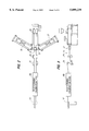
- FIG. 2 is a diagrammatic top plan view of a production line for continuously manufacturing tubular plastic fencing components in accordance with the present invention.
- FIG. 3 is a diagrammatic side view of the production line shown in FIG. 2 (side extruders omitted for clarity).
- FIG. 4 is a diagrammatic side view of longitudinal edge joint zipping and staking apparatus forming final stages of the production line shown in FIGS. 2 and 3.
- FIG. 5 is a cross-sectional view illustrating a first stage of a longitudinal edge joint zipping (interlocking) operation/apparatus of the production line shown in FIGS. 2 and 3.
- FIG. 6 is a cross-sectional view of a second stage of a longitudinal edge joint zipping (interlocking) operation/apparatus of the production line shown in FIGS. 2 and 3.
- FIG. 7 is a diagrammatic cross-sectional view illustrating a longitudinal edge joint staking operation/apparatus of the production line shown in FIGS. 2 and 3.
- FIG. 8 is a front elevational view of a circular blade used in the staking operation/apparatus of FIG. 7.
- FIG. 9 is a close-up partial front elevational view depicting the teeth of the blade of FIG. 8.
- FIG. 10 is a transverse partial cross-sectional view of a tubular fencing component in accordance with the invention, showing particularly the longitudinal edge joint after it has been staked.
- FIG. 11 is a cross-sectional view taken on line 11--11 of FIG. 10.
- FIGS. 1A-1E illustrated are the profiles of several different elongated tubular fencing components in accordance with the present invention.
- the components are used in combination with each other, and with other components, to form modular plastic fencing systems designed to suit different needs.
- FIG. 1A depicts a top or bottom rail 1 having a length-wise extending recess 3 into which a vertical picket 5 (FIG. 1D) may be fit.
- FIG. 2B depicts an intermediate rail 7 having recesses 9,11 running along top and bottom edges, for insertion of vertical pickets 5.
- FIG. 1C illustrates a simpler horizontal rail structure 13 designed to be used with separate connectors for attachment to other fencing components.
- FIG. 1E shows a square fence post 15.
- each of the components of FIGS. 1A-1E is die-formed from a flat sheet of plastic material, e.g., PVC. This is made feasible by the inclusion in each design of an aesthetically acceptable (concealed) and structurally sound longitudinal edge joint 17a-17e (to be described in detail).
- FIGS. 2 and 3 illustrate a production line for continuously manufacturing tubular plastic fencing components in accordance with the present invention.
- the process begins with the extrusion of a monolithic substantially planar sheet of plastic material 19 out of a sheet die 21.
- Sheet 19 may comprise one or more layers.
- Sheet 19 may, e.g., comprise a separate capstock layer and substrate layer supplied to sheet die 21 from separate extruders 23, 25 at approximately 400° F.
- a third extruder 27 may be used to introduce a color streaking material, in order to provide a natural wood-simulating color variegation.
- the capstock material may be formulated as a weatherable exterior material and may include as its primary components PVC resin and titanium dioxide.
- the substrate may be formulated as a rigid underlayment material and may include as its primary components a PVC resin and an acrylic monomer.
- the thickness of sheet 19 will be determined by the width of the opening of sheet die 21. With profile extrusion, a minimum wall thickness of about 0.150" is necessary to avoid collapse or warpage of a tubular structure before it fully hardens (reaches crystalline equilibrium). On the other hand, thickness is not a significant limiting factor in the extrusion of a flat sheet to be formed into fencing components. The inventor has found that a wall thickness of 0.070" is more than adequate for most fencing applications; this thickness of sheet can be extruded without difficulty. Accordingly, significant plastic material savings can be realized with the present invention.
- sheet 19 is drawn down (stress relieved) at a set of rolls 29 positioned within 24" of the exit of extrusion die 21.
- the temperature of the sheet at this stage will typically be approximately 370° F.
- a surface texture pattern e.g., simulated wood grain
- plastic sheet 19 enters a cooling set of rolls 31 serving to stabilize the material temperature to approximately 280° F.
- post forming calibration tank 99 comprises a series of tool steel dies through which plastic sheet material 19 is drawn by a puller, e.g., pinch roller or the like (not shown).
- the dies form slot-like passageways that converge in a step or continuous fashion toward the desired end profile.
- the dies are submerged in a cooling liquid, e.g., water, which quickly reduces the temperature of sheet 19 to approximately 220° F. As the material passes through the dies, it is forced to conform to the die walls by a liquid vacuum applied to die interiors.
- mandrel 101 comprises a rail 103 having a channel 104 formed on its underside.
- Rail 103 is cantilever mounted to a base 105. (Other arrangements may obviously be used.) As seen in FIG. 5 (illustrating formation of a post as shown in FIG. 1E), when plastic sheet 19 has left post forming calibration tank 99, it has a generally tubular shape, with longitudinal edge portions 107a,b terminating in respective cooperative clip members 109a,b. Initially, longitudinal edge portions 107a,b are slightly separated and pliable enough to allow the generally tubular (but slightly open) shape to pass over base 105 and onto mandrel rail 103.
- the generally tubular shape passes into a "zipping" guide stage 111, wherein a series of finger-like guide members 113a, 113b (FIGS. 5-6) arranged adjacent mandrel rail 103 cooperate with the mandrel rail to progressively bring together and interlock clip members 109a,b in overlapping relation.
- clip members 109a,b serve to hold peripheral side portions 110a, 110b of the generally tubular shape together in slightly spaced or abutted relation, thereby substantially concealing the longitudinal edge portions, including clip members 109a,b, from view.
- the closed generally tubular shape passes to a "staking" stage, wherein the overlapping portions of clip members 109a,b are “staked” together at longitudinally spaced locations.
- “staking” refers generally to the creation of discrete points of attachment formed by nested deformations of one layer into the other.
- the invention is not limited to such staking, but also includes other forms of plastic bonding such as ultrasonic welding.
- the resultant elongated tubular shape can be cut into segments of a desired length. With the process of the present invention, throughput on the order of 45-50 fpm can be obtained. This represents a substantial increase over the 12-15 fpm throughput obtainable with profile extrusion.
- the staking apparatus comprises a circular blade 115 rotatably mounted adjacent mandrel rail 103, directly downstream of zipping guides 111.
- Blade 115 is sized and positioned such that an outer circumferential edge portion 117 thereof, comprising teeth 119, rotates to pass between peripheral side portions 110a,b and into contact with an outermost one of the overlapping portions of clip members 109a,b.
- a longitudinal slot 121 is formed within channel 104 of mandrel rail 103. Teeth 119 press the overlapping portions into slot 121 to create nested deformations (stakes) 122 (see FIGS. 10-11) serving to secure the overlapping portions against relative motion, particularly motion in the shear plane defined between the layers.
- FIG. 7 The staking process/apparatus is seen most clearly FIG. 7.
- the staking of an intermediate rail 7 of the type seen in FIG. 1B is primarily illustrated, with use of the same apparatus to form a square post 15 (FIGS. 1E, 5 and 6) being depicted with hatched lines.
- mandrel rail 103 is mounted between two bars 123a,b in such a manner as to correspond to the interior shape of rail 7. It can also be seen that a hub 125 of circular blade 115 has an outer portion 117 shaped to fit closely within recess 11.
- hub 125 rotatably mounts blade 115 for rotation on a stationary axle 126.
- Attached to an outer rotating part of hub 125 is a gear or sprocket 127 driven, through a chain 129 and drive gear 131, by a drive motor 133.
- the speed of drive motor 133 is controlled by a known program logic controller 135 to compensate for line fluctuations and synchronize the rotation speed of blade 115 with the feed speed of plastic material 19.
- teeth 119 comprise pairs of adjacent teeth 119a,b extending in opposing circumferential directions of blade 115.
- shape of stakes 122 corresponds generally to the shape of teeth 119a,b.
- teeth 119a,b serve to create stakes directed in opposed longitudinal directions of the tubular fencing component.
- An arrangement of stakes extending in opposing longitudinal directions has been found to provide significantly increased strength (particularly in the opposing longitudinal directions) as compared with a single stake directed normally into the layers.
- Teeth 119 should be thick enough to create a strong stake.
- blade 115 should be thin enough to allow it to easily pass between the peripheral side portions (e.g., 110a, 110b) held together by interlocked clip members 109a,b.
- blade 115 (including teeth 119) are integrally formed from a sheet of tool steel having a thickness of 0.063".
- the shape and size of the teeth can also vary.
- blade positioning, and tooth shapes and sizes should be chosen such that the staking of the material deforms but does not pierce the plastic layers. Occurrences of piercing have been found to significantly reduce the attainable joint strength. As a rule of thumb, it is believed that material deformations (offsets) approximately equal to the thickness of the plastic sheet material being processed will yield good results.
- blade 15 has a diameter d, exclusive of the teeth, of 6".
- Teeth 119 are configured in pairs spaced along the circumference of the blade at 11/2" centers. (As a result, pairs of stakes are also spaced at 11/2" centers.)
- Adjacent teeth of each pair are generally triangular in shape and symmetrical with respect to each other. The teeth have a height h of 0.221".
- the tips of the teeth are rounded to a radius r 1 of 0.010, and the corners between the adjacent triangular teeth are rounded to a radius r 2 of 0.200.
- the rounding of the tips of the teeth helps to provide a material offset or deformation without piercing the material, while the rounding between the teeth serves primarily to avoid stress concentrations in the blade.
Abstract
Description
Claims (9)
Priority Applications (1)
| Application Number | Priority Date | Filing Date | Title |
|---|---|---|---|
| US08/593,411 US5899239A (en) | 1996-01-29 | 1996-01-29 | Tubular fencing components formed from plastic sheet material |
Applications Claiming Priority (1)
| Application Number | Priority Date | Filing Date | Title |
|---|---|---|---|
| US08/593,411 US5899239A (en) | 1996-01-29 | 1996-01-29 | Tubular fencing components formed from plastic sheet material |
Publications (1)
| Publication Number | Publication Date |
|---|---|
| US5899239A true US5899239A (en) | 1999-05-04 |
Family
ID=24374599
Family Applications (1)
| Application Number | Title | Priority Date | Filing Date |
|---|---|---|---|
| US08/593,411 Expired - Lifetime US5899239A (en) | 1996-01-29 | 1996-01-29 | Tubular fencing components formed from plastic sheet material |
Country Status (1)
| Country | Link |
|---|---|
| US (1) | US5899239A (en) |
Cited By (15)
| Publication number | Priority date | Publication date | Assignee | Title |
|---|---|---|---|---|
| US6520215B2 (en) * | 2001-02-27 | 2003-02-18 | Hayes-Albion Corporation | Tubular bar with integral rolled locking system and method of making same |
| US20050072966A1 (en) * | 2003-02-28 | 2005-04-07 | Jeffrey Bergh | Fiber cement fence system |
| US20050115191A1 (en) * | 2003-12-02 | 2005-06-02 | Owoc Anthony L. | Single piece post cladding element, method of cladding a post and method of forming a cladding element |
| US20050276524A1 (en) * | 2002-03-08 | 2005-12-15 | Nossi Taheri | Leak resistant tamper evident reclosable plastic bag |
| US20060010824A1 (en) * | 2004-07-15 | 2006-01-19 | Waters Eric S | Cladding assembly and method of cladding posts |
| US20060010823A1 (en) * | 2004-07-15 | 2006-01-19 | Waters Eric S | Cladding assembly and method of cladding posts |
| US20060033090A1 (en) * | 2004-07-23 | 2006-02-16 | James Fattori | Thermoplastic fencing construction and method of assembly thereof |
| US20060033091A1 (en) * | 2004-07-23 | 2006-02-16 | Lmt Mercer Group Inc. | Thermoplastic fencing construction and method of assembly thereof |
| US20060201699A1 (en) * | 2005-03-14 | 2006-09-14 | Burdy John E | Protective sheath with integral biased flap closure |
| US20130239512A1 (en) * | 2010-03-19 | 2013-09-19 | Weihong Yang | Steel and wood composite structure with metal jacket wood studs and rods |
| US20130288068A1 (en) * | 2012-04-26 | 2013-10-31 | John Bernard | Ws2 |
| US20130295404A1 (en) * | 2012-05-02 | 2013-11-07 | John Bernard | Ws3 |
| US8668797B2 (en) | 2004-07-23 | 2014-03-11 | Lmt Mercer Group Inc. | Method of assembly of thermoplastic fencing |
| US8910455B2 (en) | 2010-03-19 | 2014-12-16 | Weihong Yang | Composite I-beam member |
| US20150152905A1 (en) * | 2013-12-02 | 2015-06-04 | Denso Corporation | Fitted housing |
Citations (20)
| Publication number | Priority date | Publication date | Assignee | Title |
|---|---|---|---|---|
| US207606A (en) * | 1878-09-03 | Improvement in sheet-metal pipes | ||
| US697955A (en) * | 1901-10-16 | 1902-04-15 | Packers Sanitary Can Company | Solderless side seam for tin cans or other metallic vessels. |
| US1034483A (en) * | 1910-11-14 | 1912-08-06 | Jackson Fence Company | Metallic tube. |
| US1796015A (en) * | 1927-05-05 | 1931-03-10 | Francis James Henry Edward | Manufacture of containers and tubes from sheet metal |
| US1891740A (en) * | 1930-11-18 | 1932-12-20 | American Brass Co | Extruded shapes with interlocked joints and method of making |
| US1984232A (en) * | 1933-09-29 | 1934-12-11 | Peremi Edmund | Extruded shapes with interlock and method of making same |
| US2522097A (en) * | 1946-01-10 | 1950-09-12 | Cookson William | Joint between resilient sheet material parts |
| US2703110A (en) * | 1953-03-06 | 1955-03-01 | Reeves Steel And Mfg Company | Interrupted lock joint for metal pipes |
| US2749155A (en) * | 1952-11-10 | 1956-06-05 | Kaiser Aluminium Chem Corp | Resilient pipe joint with sheet metal clamp member |
| US2975874A (en) * | 1958-04-01 | 1961-03-21 | Pagan Alberto | Girder made up of structural members |
| US3154037A (en) * | 1960-12-13 | 1964-10-27 | Mayrath Martin | Apparatus for anchoring the seams of lock seam tubing |
| US3656515A (en) * | 1969-06-06 | 1972-04-18 | Voest Ag | Shaped tube |
| US3728837A (en) * | 1971-02-25 | 1973-04-24 | A Kiefer | Modular structures |
| US4725463A (en) * | 1985-03-05 | 1988-02-16 | Ulv Pty. Limited | Selectively foldable elongated member |
| US4727702A (en) * | 1986-11-03 | 1988-03-01 | Kathleen T. Baker | Panel useful for gates or fence sections |
| US4788088A (en) * | 1985-10-04 | 1988-11-29 | Kohl John O | Apparatus and method of making a reinforced plastic laminate structure and products resulting therefrom |
| US5100109A (en) * | 1989-08-03 | 1992-03-31 | Robbins Edward S Iii | Fence board construction and related process |
| US5215290A (en) * | 1992-05-19 | 1993-06-01 | Khalessi Hamid R | Plastic fence |
| US5303900A (en) * | 1992-03-02 | 1994-04-19 | Zulick Iii James E | Plastic security handrail system and connectors therefor |
| US5421556A (en) * | 1993-03-02 | 1995-06-06 | Associated Materials Inc. | Modular fencing components |
-
1996
- 1996-01-29 US US08/593,411 patent/US5899239A/en not_active Expired - Lifetime
Patent Citations (20)
| Publication number | Priority date | Publication date | Assignee | Title |
|---|---|---|---|---|
| US207606A (en) * | 1878-09-03 | Improvement in sheet-metal pipes | ||
| US697955A (en) * | 1901-10-16 | 1902-04-15 | Packers Sanitary Can Company | Solderless side seam for tin cans or other metallic vessels. |
| US1034483A (en) * | 1910-11-14 | 1912-08-06 | Jackson Fence Company | Metallic tube. |
| US1796015A (en) * | 1927-05-05 | 1931-03-10 | Francis James Henry Edward | Manufacture of containers and tubes from sheet metal |
| US1891740A (en) * | 1930-11-18 | 1932-12-20 | American Brass Co | Extruded shapes with interlocked joints and method of making |
| US1984232A (en) * | 1933-09-29 | 1934-12-11 | Peremi Edmund | Extruded shapes with interlock and method of making same |
| US2522097A (en) * | 1946-01-10 | 1950-09-12 | Cookson William | Joint between resilient sheet material parts |
| US2749155A (en) * | 1952-11-10 | 1956-06-05 | Kaiser Aluminium Chem Corp | Resilient pipe joint with sheet metal clamp member |
| US2703110A (en) * | 1953-03-06 | 1955-03-01 | Reeves Steel And Mfg Company | Interrupted lock joint for metal pipes |
| US2975874A (en) * | 1958-04-01 | 1961-03-21 | Pagan Alberto | Girder made up of structural members |
| US3154037A (en) * | 1960-12-13 | 1964-10-27 | Mayrath Martin | Apparatus for anchoring the seams of lock seam tubing |
| US3656515A (en) * | 1969-06-06 | 1972-04-18 | Voest Ag | Shaped tube |
| US3728837A (en) * | 1971-02-25 | 1973-04-24 | A Kiefer | Modular structures |
| US4725463A (en) * | 1985-03-05 | 1988-02-16 | Ulv Pty. Limited | Selectively foldable elongated member |
| US4788088A (en) * | 1985-10-04 | 1988-11-29 | Kohl John O | Apparatus and method of making a reinforced plastic laminate structure and products resulting therefrom |
| US4727702A (en) * | 1986-11-03 | 1988-03-01 | Kathleen T. Baker | Panel useful for gates or fence sections |
| US5100109A (en) * | 1989-08-03 | 1992-03-31 | Robbins Edward S Iii | Fence board construction and related process |
| US5303900A (en) * | 1992-03-02 | 1994-04-19 | Zulick Iii James E | Plastic security handrail system and connectors therefor |
| US5215290A (en) * | 1992-05-19 | 1993-06-01 | Khalessi Hamid R | Plastic fence |
| US5421556A (en) * | 1993-03-02 | 1995-06-06 | Associated Materials Inc. | Modular fencing components |
Cited By (26)
| Publication number | Priority date | Publication date | Assignee | Title |
|---|---|---|---|---|
| US6520215B2 (en) * | 2001-02-27 | 2003-02-18 | Hayes-Albion Corporation | Tubular bar with integral rolled locking system and method of making same |
| US6840571B1 (en) | 2001-02-27 | 2005-01-11 | Trim Trends Co, Inc. | Tubular bar with integral rolled locking system and method of making same |
| US20050276524A1 (en) * | 2002-03-08 | 2005-12-15 | Nossi Taheri | Leak resistant tamper evident reclosable plastic bag |
| US20050072966A1 (en) * | 2003-02-28 | 2005-04-07 | Jeffrey Bergh | Fiber cement fence system |
| US20050115191A1 (en) * | 2003-12-02 | 2005-06-02 | Owoc Anthony L. | Single piece post cladding element, method of cladding a post and method of forming a cladding element |
| US7168220B2 (en) * | 2003-12-02 | 2007-01-30 | Certainteed Corporation | Single piece post cladding element, method of cladding a post and method of forming a cladding element |
| US20060010823A1 (en) * | 2004-07-15 | 2006-01-19 | Waters Eric S | Cladding assembly and method of cladding posts |
| US20060010824A1 (en) * | 2004-07-15 | 2006-01-19 | Waters Eric S | Cladding assembly and method of cladding posts |
| US8322114B2 (en) | 2004-07-15 | 2012-12-04 | Certainteed Corporation | Cladding assembly and method of cladding posts |
| US20080289295A1 (en) * | 2004-07-15 | 2008-11-27 | Certain Teed Corporation | Cladding assembly and method of cladding posts |
| US8074424B2 (en) | 2004-07-15 | 2011-12-13 | Certainteed Corporation | Cladding assembly and method of cladding posts |
| US20060033090A1 (en) * | 2004-07-23 | 2006-02-16 | James Fattori | Thermoplastic fencing construction and method of assembly thereof |
| US20060033091A1 (en) * | 2004-07-23 | 2006-02-16 | Lmt Mercer Group Inc. | Thermoplastic fencing construction and method of assembly thereof |
| US8668797B2 (en) | 2004-07-23 | 2014-03-11 | Lmt Mercer Group Inc. | Method of assembly of thermoplastic fencing |
| US7204898B2 (en) | 2004-07-23 | 2007-04-17 | Lmt Mercer Group Inc. | Thermoplastic fencing construction and method of assembly thereof |
| US20110012078A1 (en) * | 2004-07-23 | 2011-01-20 | Lmt Mercer Group Inc. | Thermoplastic fencing construction |
| US7442875B2 (en) * | 2005-03-14 | 2008-10-28 | Federal-Mogul World Wide, Inc. | Protective sheath with integral biased flap closure |
| US20060201699A1 (en) * | 2005-03-14 | 2006-09-14 | Burdy John E | Protective sheath with integral biased flap closure |
| US20130239512A1 (en) * | 2010-03-19 | 2013-09-19 | Weihong Yang | Steel and wood composite structure with metal jacket wood studs and rods |
| US8820033B2 (en) * | 2010-03-19 | 2014-09-02 | Weihong Yang | Steel and wood composite structure with metal jacket wood studs and rods |
| US8910455B2 (en) | 2010-03-19 | 2014-12-16 | Weihong Yang | Composite I-beam member |
| US20130288068A1 (en) * | 2012-04-26 | 2013-10-31 | John Bernard | Ws2 |
| US9010069B2 (en) * | 2012-04-26 | 2015-04-21 | John P. Bernard | Protective post covering |
| US20130295404A1 (en) * | 2012-05-02 | 2013-11-07 | John Bernard | Ws3 |
| US9032694B2 (en) * | 2012-05-02 | 2015-05-19 | John Bernard | Ws3 |
| US20150152905A1 (en) * | 2013-12-02 | 2015-06-04 | Denso Corporation | Fitted housing |
Similar Documents
| Publication | Publication Date | Title |
|---|---|---|
| US5899239A (en) | Tubular fencing components formed from plastic sheet material | |
| US4505084A (en) | Wide panel, panel assembly | |
| US4364253A (en) | Panel forming apparatus | |
| US4130974A (en) | Siding panels and the method of production | |
| US20020170159A1 (en) | System for fabricating contour muntin bars from sheet material | |
| EP2177702B1 (en) | Hollow profile, in particular separator tube for insulation glazing and device and method for producing same | |
| US20010049918A1 (en) | Staggered look shake siding | |
| US7086153B2 (en) | Method and apparatus for manufacturing heat exchanger tube | |
| CN1131919A (en) | Apparatus for forming profiles on strip materials | |
| US20030192281A1 (en) | Seamless siding and method and apparatus for making a seamless siding panel | |
| EP1634660B1 (en) | Methods and apparatus for forming stiffening structures in a strip material | |
| WO1984000392A1 (en) | Structural beam and panel systems and methods and apparatus for making the same | |
| US4796393A (en) | Decorative awning and facia structures and methods and apparatus for forming the same | |
| EP0976466A2 (en) | Method and device for the manufacture of a tube from strip material | |
| WO1984004263A1 (en) | Method and apparatus for rolling flanged section | |
| US4945624A (en) | Method of forming and assembling decorative awning and building facia | |
| US3722052A (en) | Method of forming a structural unit | |
| CN1081526C (en) | Method and apparatus for structural foam panels | |
| DE60220950T2 (en) | SHEET MOLDING | |
| US7424795B2 (en) | Method for extruding and product of the method | |
| JP2011218799A (en) | Patterning method for aluminum shape and aluminum shape | |
| JPH0957352A (en) | Production of steel shapes with lip | |
| DE2721242A1 (en) | METHOD AND DEVICE FOR CONTINUOUS PIPE PRODUCTION | |
| JP2000096883A (en) | Synthetic resin-made fence plate panel and its manufacture | |
| CN210454280U (en) | Tubular product section bar decorative pattern stamping equipment and decorative pattern stamping die thereof |
Legal Events
| Date | Code | Title | Description |
|---|---|---|---|
| AS | Assignment |
Owner name: ASSOCIATED MATERIALS, INCORPORATED, OHIO Free format text: ASSIGNMENT OF ASSIGNORS INTEREST;ASSIGNOR:COULIS, MARK L.;REEL/FRAME:007909/0658 Effective date: 19960415 |
|
| STCF | Information on status: patent grant |
Free format text: PATENTED CASE |
|
| AS | Assignment |
Owner name: UBS AG STAMFORD BRANCH AS, ADMINISTRATIVE AGENT, C Free format text: SECURITY AGREEMENT;ASSIGNOR:ASSOCIATED MATERIALS INCORPORATED;REEL/FRAME:012937/0353 Effective date: 20020419 |
|
| FPAY | Fee payment |
Year of fee payment: 4 |
|
| FPAY | Fee payment |
Year of fee payment: 8 |
|
| AS | Assignment |
Owner name: ASSOCIATED MATERIALS INC., NOW KNOWN AS ASSOCIATED Free format text: RELEASE OF SECURITY INTEREST RECORDED ON REEL 012937, FRAME 0353;ASSIGNOR:UBS AG, STAMFORD BRANCH, AS ADMINISTRATIVE AGENT;REEL/FRAME:021731/0367 Effective date: 20081003 |
|
| AS | Assignment |
Owner name: DEUTSCHE BANK TRUST COMPANY AMERICAS, AS COLLATERA Free format text: SECURITY AGREEMENT;ASSIGNORS:ASSOCIATED MATERIALS, LLC;ASSOCIATED MATERIALS FINANCE, INC.;GENTEK HOLDINGS, LLC;AND OTHERS;REEL/FRAME:023627/0731 Effective date: 20091105 |
|
| AS | Assignment |
Owner name: ASSOCIATED MATERIALS, LLC, OHIO Free format text: RELEASE BY SECURED PARTY;ASSIGNOR:DEUTSCHE BANK TRUST COMPANY AMERICAS AS COLLATERAL AGENT;REEL/FRAME:025137/0732 Effective date: 20101013 Owner name: GENTEK BUILDING PRODUCTS, INC., OHIO Free format text: RELEASE BY SECURED PARTY;ASSIGNOR:DEUTSCHE BANK TRUST COMPANY AMERICAS AS COLLATERAL AGENT;REEL/FRAME:025137/0732 Effective date: 20101013 |
|
| AS | Assignment |
Owner name: UBS AG, STAMFORD BRANCH, AS US COLLATERAL AGENT, C Free format text: SECURITY AGREEMENT;ASSIGNOR:ASSOCIATED MATERIALS, LLC;REEL/FRAME:025150/0324 Effective date: 20101013 |
|
| FPAY | Fee payment |
Year of fee payment: 12 |
|
| AS | Assignment |
Owner name: WELLS FARGO BANK, NATIONAL ASSOCIATION, AS NOTES C Free format text: SECURITY AGREEMENT;ASSIGNOR:ASSOCIATED MATERIALS, LLC;REEL/FRAME:025326/0586 Effective date: 20101013 |
|
| AS | Assignment |
Owner name: H&F FINCO LLC, NEW YORK Free format text: SECURITY INTEREST;ASSIGNOR:ASSOCIATED MATERIALS, LLC;REEL/FRAME:037777/0974 Effective date: 20160219 |
|
| AS | Assignment |
Owner name: H&F FINCO LLC, NEW YORK Free format text: CORRECTIVE ASSIGNMENT TO CORRECT THE LANGUAGE IN THE INTRODUCTORY PARAGRAPH AT THE TOP OF THE FIRST PAGE PREVIOUSLY RECORDED AT REEL: 037777 FRAME: 0974. ASSIGNOR(S) HEREBY CONFIRMS THE SECURITY INTEREST;ASSIGNOR:ASSOCIATED MATERIALS, LLC;REEL/FRAME:037991/0831 Effective date: 20160219 |
|
| AS | Assignment |
Owner name: ASSOCIATED MATERIALS, LLC, OHIO Free format text: RELEASE OF SECURITY INTEREST IN PATENTS PREVIOUSLY RECORDED AT REEL/FRAME (025326/0586);ASSIGNOR:WELLS FARGO BANK, NATIONAL ASSOCIATION, AS NOTES COLLATERAL AGENT;REEL/FRAME:040921/0948 Effective date: 20161122 Owner name: ASSOCIATED MATERIALS, LLC, OHIO Free format text: RELEASE OF SECURITY INTEREST IN PATENTS PREVIOUSLY RECORDED AT REEL/FRAME (037991/0831);ASSIGNOR:H&F FINCO LLC;REEL/FRAME:040921/0842 Effective date: 20161122 |
|
| AS | Assignment |
Owner name: ASSOCIATED MATERIALS, LLC, OHIO Free format text: RELEASE OF SECURITY INTEREST IN PATENTS;ASSIGNOR:UBS AG, STAMFORD BRANCH;REEL/FRAME:059337/0299 Effective date: 20220308 |