US5917606A - Photometric flow apparatus for small sample volumes and method of making same - Google Patents

Photometric flow apparatus for small sample volumes and method of making same Download PDF

Info

Publication number
US5917606A
US5917606A US08/709,017 US70901796A US5917606A US 5917606 A US5917606 A US 5917606A US 70901796 A US70901796 A US 70901796A US 5917606 A US5917606 A US 5917606A
Authority
US
United States
Prior art keywords
cell body
flow channel
cell
channel
capillary
Prior art date
Legal status (The legal status is an assumption and is not a legal conclusion. Google has not performed a legal analysis and makes no representation as to the accuracy of the status listed.)
Expired - Lifetime
Application number
US08/709,017
Inventor
Patrick Kaltenbach
Current Assignee (The listed assignees may be inaccurate. Google has not performed a legal analysis and makes no representation or warranty as to the accuracy of the list.)
Agilent Technologies Inc
Original Assignee
Hewlett Packard Co
Priority date (The priority date is an assumption and is not a legal conclusion. Google has not performed a legal analysis and makes no representation as to the accuracy of the date listed.)
Filing date
Publication date
Application filed by Hewlett Packard Co filed Critical Hewlett Packard Co
Assigned to HEWLETT-PACKARD COMPANY reassignment HEWLETT-PACKARD COMPANY ASSIGNMENT OF ASSIGNORS INTEREST (SEE DOCUMENT FOR DETAILS). Assignors: HEWLETT-PACKARD GMBH
Application granted granted Critical
Publication of US5917606A publication Critical patent/US5917606A/en
Assigned to HEWLETT-PACKARD COMPANY, A DELAWARE CORPORATION reassignment HEWLETT-PACKARD COMPANY, A DELAWARE CORPORATION MERGER (SEE DOCUMENT FOR DETAILS). Assignors: HEWLETT-PACKARD COMPANY, A CALIFORNIA CORPORATION
Assigned to AGILENT TECHNOLOGIES INC reassignment AGILENT TECHNOLOGIES INC ASSIGNMENT OF ASSIGNORS INTEREST (SEE DOCUMENT FOR DETAILS). Assignors: HEWLETT-PACKARD COMPANY
Anticipated expiration legal-status Critical
Expired - Lifetime legal-status Critical Current

Links

Images

Classifications

    • GPHYSICS
    • G01MEASURING; TESTING
    • G01NINVESTIGATING OR ANALYSING MATERIALS BY DETERMINING THEIR CHEMICAL OR PHYSICAL PROPERTIES
    • G01N21/00Investigating or analysing materials by the use of optical means, i.e. using sub-millimetre waves, infrared, visible or ultraviolet light
    • G01N21/01Arrangements or apparatus for facilitating the optical investigation
    • G01N21/03Cuvette constructions
    • G01N21/05Flow-through cuvettes
    • GPHYSICS
    • G01MEASURING; TESTING
    • G01NINVESTIGATING OR ANALYSING MATERIALS BY DETERMINING THEIR CHEMICAL OR PHYSICAL PROPERTIES
    • G01N27/00Investigating or analysing materials by the use of electric, electrochemical, or magnetic means
    • G01N27/26Investigating or analysing materials by the use of electric, electrochemical, or magnetic means by investigating electrochemical variables; by using electrolysis or electrophoresis
    • G01N27/416Systems
    • G01N27/447Systems using electrophoresis
    • G01N27/44704Details; Accessories
    • G01N27/44717Arrangements for investigating the separated zones, e.g. localising zones
    • G01N27/44721Arrangements for investigating the separated zones, e.g. localising zones by optical means
    • GPHYSICS
    • G01MEASURING; TESTING
    • G01NINVESTIGATING OR ANALYSING MATERIALS BY DETERMINING THEIR CHEMICAL OR PHYSICAL PROPERTIES
    • G01N30/00Investigating or analysing materials by separation into components using adsorption, absorption or similar phenomena or using ion-exchange, e.g. chromatography or field flow fractionation
    • G01N30/02Column chromatography
    • G01N30/62Detectors specially adapted therefor
    • G01N30/74Optical detectors
    • GPHYSICS
    • G01MEASURING; TESTING
    • G01NINVESTIGATING OR ANALYSING MATERIALS BY DETERMINING THEIR CHEMICAL OR PHYSICAL PROPERTIES
    • G01N21/00Investigating or analysing materials by the use of optical means, i.e. using sub-millimetre waves, infrared, visible or ultraviolet light
    • G01N21/01Arrangements or apparatus for facilitating the optical investigation
    • G01N21/03Cuvette constructions
    • G01N2021/0346Capillary cells; Microcells
    • GPHYSICS
    • G01MEASURING; TESTING
    • G01NINVESTIGATING OR ANALYSING MATERIALS BY DETERMINING THEIR CHEMICAL OR PHYSICAL PROPERTIES
    • G01N30/00Investigating or analysing materials by separation into components using adsorption, absorption or similar phenomena or using ion-exchange, e.g. chromatography or field flow fractionation
    • G01N30/02Column chromatography
    • G01N30/62Detectors specially adapted therefor
    • G01N30/74Optical detectors
    • G01N2030/746Optical detectors detecting along the line of flow, e.g. axial
    • GPHYSICS
    • G01MEASURING; TESTING
    • G01NINVESTIGATING OR ANALYSING MATERIALS BY DETERMINING THEIR CHEMICAL OR PHYSICAL PROPERTIES
    • G01N2201/00Features of devices classified in G01N21/00
    • G01N2201/06Illumination; Optics
    • G01N2201/064Stray light conditioning
    • G01N2201/0642Light traps; baffles

Definitions

  • the present invention relates to spectroscopy, and more particularly to spectroscopy of small samples in solution.
  • sample analysis instrumentation and especially in separation systems such as liquid chromatography and capillary electrophoresis systems, smaller dimensions generally result in improved performance characteristics and at the same time result in reduced analysis costs.
  • capillaries having small inside diameters ranging from 5 to 100 micrometers for handling the extremely small volumes of flowing liquid samples.
  • micro-column liquid chromatography As an example, the micro-column liquid chromatography ( ⁇ LC) has been described wherein columns having diameters of 100-200 ⁇ m are employed as compared to columns having diameters of around 4.6 mm.
  • capillary electrophoresis a separation technique carried out in capillaries having a diameter of 5-100 ⁇ m.
  • the capillary electrophoresis has been demonstrated to be useful as a method for the separation of small solutes. See for example Journal of Chromatography, vol. 218, p. 209, 1981; and Analytical Chemistry, vol. 53, p. 1298, 1981.
  • the absorbance (A) of a sample in a 25 ⁇ m capillary is 400 times lower than to the absorbance of a conventional cell having a pathlength of 1 cm, as typically used in ultraviolet, visible (UV/Vis) spectroscopy.
  • Standard detection cells used in conventional liquid chromatography instruments have the disadvantage that their cell volume is about of three orders of magnitude too large to handle the small nano-liter (nl) sample volumes of the above mentioned capillary separation techniques. Scaling down the conventional shape of these cells to match the nl volumes is problematic both from the manufacturing point of view and from the photometric aspect. For example, to get a cell volume of approximately 10 nl with a pathlength of 1 mm, the circular inner diameter of such a cell has to be smaller than 120 ⁇ m.
  • U.S. Pat. No. 5,061,361 describes an approach entailing micro-manipulation of the capillary flow cell to form a bubble at the point of detection.
  • U.S. Pat. No. 5,141,548 describes the use of a capillary having a Z-shaped configuration with detection performed across the extended portion of the Z.
  • U.S. Pat. No. 5,273,633 describes a further approach to increased detection pathlengths in the field of capillary electrophoresis where a reflecting surface exterior of the capillary is provided.
  • the system also includes an incident window and an exit window downstream of the incident window. Light entering the incident window passes through a section of the capillary by multiple internal reflections before passing through the exit window where it is detected. The multiple internal reflections yield an effective increase in pathlength.
  • parts of the light beam do not propagate through the center of the capillary. In all of these approaches at least part of the beam propagates through the transparent capillary wall, and does not contact with the sample. This decreases the linearity of the detector and reduces the effective path length, which determines the sensitivity of the detector.
  • the European patent application No. 92112114.1 describes a photometric apparatus, having a flow cell coated with a fluoropolymer to guide the light beam axially along a liquid filled tube or capillary.
  • the fluoropolymer In order to get total internal reflection of the light beam at the cell wall, the fluoropolymer must have a refractive index lower the refractive index of the liquid in the tube.
  • these polymers are available, they are very expensive and the stability of the coating when exposed to solvents and acids limits its usability.
  • a capillary is illuminated with light from a UV/vis light source and a slit of width o is placed behind the capillary to block stray light through the capillary wall.
  • the light transmitted through the slit is detected.
  • ⁇ ( ⁇ ) extinction of molar absorption coefficient as a function of the wavelength
  • FIG. 10 is a typical plot of detector response, plotted as absorbance (A( ⁇ )) vs. molar solute concentration (C).
  • the lower detection limit is determined by the baseline noise of the detector and its sensitivity, as determined by the slope dA/dc of the detector response linear range absorbance values in the FIG. 10 plot.
  • the upper limit of detection is determined by the where the detector response is no longer linear, as occurs at higher concentration levels.
  • FIG. 11 is a cross sectional view of a prior art flow cell used in liquid chromatography.
  • the cell assembly 1100 is positioned between a radiation source 1102 and a photodetector device 1104.
  • a lens 1106 is arranged between the radiation light source 1102 and the cell assembly 1100 for focusing the radiation emitted from the radiation source 1102.
  • An inlet tube 1122 and an outlet tube 1124 are connected by threaded fittings 1126 to an inlet port 1128 and an outlet port 1130, respectively, to supply the sample to and from the cell 1100.
  • the tubes 1122, 1124 normally made of stainless steel are connected by threaded fittings 1126 to the cell body 1108.
  • these cells 1100 have cell volumes 1110 in the range of 3 to 15 ⁇ l.
  • the cell 1100 has an inner diameter of 0.5 to 1.5 mm and a length of 3 to 10 mm. Because the inner diameter of the cell 1100 is such that light rays are prevented from striking the cell wall, there are unpredictable disturbances of the measured photometric signal. Apertures, conical cell shapes and/or lenses are also used to avoid this problem.
  • deuterium lamps are used as radiation source 1102 for UV/Vis absorbance measurements.
  • sample volumes are about three orders of magnitude smaller than described above. Accordingly, such a flow cell must be much smaller.
  • Reduced light throughput results in increased photometric noise, to prevent the desired gain in sensitivity from being achieved.
  • the present invention provides a photometric apparatus for small sample volumes comprising a cell body; a light input means arranged adjacent a first surface of the cell body; a light source emitting light of predetermined wavelength or wavelength range through the light input means; a light output means arranged adjacent a second surface of the cell body opposite to the first surface; a light detector arranged adjacent to the light output means; and a flow channel formed in the cell body; wherein surfaces of the walls of the channel have a roughness smaller than the predetermined wavelength, i.e. of the source.
  • the cell body is preferably made of non-transparent material, so that light from the light source passes through the channel, but not through the cell wall.
  • the connected capillaries preferably have an expanded inner diameter at the outlet to reduce liquid flow disturbances and to match the inner diameter of the capillary to the channel diameter. Dead volumes are avoided by butt coupling the capillary to the channel.
  • This combination allows highly sensitive and linear detection of nl liquid sample volumes while maintaining the efficiency of capillary separation techniques.
  • FIG. 1A is a cross-sectional view of a first embodiment of the present invention
  • FIGS. 1B and 1C are illustrations of the manufacturing process for the cell body
  • FIG. 2A is a ray diagram of refraction and reflection processes of a light ray incident on a surface of a transparent body
  • FIGS. 2B and 2C are ray diagrams of the difference between specular and diffuse reflection at the cell wall
  • FIG. 3 is a graph of reflectance versus incident angle at a surface of a transparent body
  • FIG. 4 is a cross-sectional view of a second embodiment of the present invention.
  • FIG. 5 is a cross-sectional view of a third embodiment of the present invention.
  • FIG. 6 is an electropherogram of the bandbroadening effect due to different diameters of the capillary and channel at the junction;
  • FIG. 7 is an electropherogram of the gain in sensitivity achieved by the present invention.
  • FIGS. 8 and 9 are respectively drawings of slit and capillary arrangements used in an on column approach.
  • FIG. 10 is a graph of the principle detector response characteristic
  • FIG. 11 is a diagram of a prior art flow cell used in liquid chromatography.
  • liquid phase analysis is used to refer to any analysis which is done on either small and/or macromolecular solutes in the liquid phase.
  • liquid phase analysis includes chromatographic separations, electrophoretic separations, and electrochromatographic separations.
  • chromatographic process generally refers to preferential separations of components, and includes reverse-phase, hydrophobic interaction, ion exchange, molecular sieve chromatography and like methods.
  • electrospheretic separation refers to the migration of particles or macromolecules having a net electric charge where the migration is influenced by an electric field. Therefore “electrophoretic separation” includes separations performed in columns packed with gels (such as poly-acrylamide, agarose and combinations thereof) as well as separations performed in solution.
  • gels such as poly-acrylamide, agarose and combinations thereof
  • electrochromatographic separation refers to combinations of electrophoretic and chromatographic techniques.
  • a flow cell according to the preferred embodiment is used for analysing small liquid sample volumes, i.e. volumes as small as 3-15 nl.
  • FIG. 1A is a cross sectional view of a photometric flow apparatus 100 according to an embodiment of the present invention.
  • the photometric flow cell 100 comprises a cell body 102 of a non-transparent material.
  • a first transparent window 104 is arranged adjacent to a first surface of the cell body 102.
  • a second transparent window 106 is arranged adjacent to a second surface of the cell body 102 opposite to the first surface.
  • a photo detector means 107 is arranged adjacent to the second transparent window 106.
  • the photodetector means 107 can include mirrors, gratings (not shown) and photo diode arrays.
  • a flow channel 108 is formed inside the cell body 102.
  • the flow channel 108 comprises three portions 108a, 108b, 108c.
  • the first portion 108a of the flow channel 108 is formed adjacent to the first transparent window 104 and extends substantially parallel to the first surface of the cell body 102.
  • the second portion 108b of the flow channel 108 extends from the first surface to the second surface of the cell body 102.
  • the third portion 108c of the flow channel 108 is formed adjacent to the second transparent window 106 and extends substantially parallel to the second surface of the cell body 102.
  • the first, second and -third portion 108a-c of the flow channel 108 include junction portions 108d. These junction portions 108d connect the respective portions 108a, 108b and 108b, 108c of the flow channel 108 preferably through an angle of 45°.
  • the transparent windows 104, 106 can be made of fused silica and may be directly fused to the cell body 102.
  • Holes 110 and 112 are provided in the cell 100 for accommodating the ends of an inlet capillary 114 and an outlet capillary 116. These holes 110 and 112 are preferably ultrasonically machined.
  • FIG. 1A a feature concerning the capillary/flow channel coupling in the present invention is shown.
  • the inlet capillary 114 has a wider ID at the capillary/flow channel junction to match the diameter to the channel width.
  • the volume within the capillary is pressurized and the capillary is rotated in a gas flame until the ID of the capillary is increased to the desired extension. This might take a few seconds.
  • the capillary is scored at the center of the cavity and an axial tension is applied.
  • the capillary will break at the center of the cavity with a clear and rectangular edge.
  • a capillary/flow channel junction is provided having gradual curves and transitions to achieve smooth flow and avoid turbulences.
  • the capillaries used for microcolumn separations such as capillary electrophoresis or ⁇ -liquid chromatography have inner diameters typically ranging from 25 to 100 ⁇ m.
  • the cell shown in FIG. 1A is designed for very small sample volumes.
  • the flow channel of the cell has a rectangular cross-section of less than 150 ⁇ 150 ⁇ m and a channel length of less than 1.3 mm, resulting in a cell volume of less than 10 nl.
  • a detection pathlenght of 1 mm results in a sensitivity up to 20 times higher than on column detection approaches using 50 ⁇ m-ID fused silica capillaries.
  • the cell body 102 is made of a non-transparent material, such as opaque black Suprasil (registered trademark) (black fused silica) available from Heraeus.
  • Suprasil registered trademark
  • black fused silica available from Heraeus.
  • the cell body 102 comprises a first and a second portion 102a and 102b.
  • a first and a second flow channel forming part 118a and 118b are arranged between the first portion 102a and the second portion 102b of the cell body 102 such that the flow channel 108 shown in FIG. 1A is formed.
  • the cell body 102 is formed by directly fusing together the first portion 102a of the cell body 102, the first and second flow channel forming parts 118a, 118b, and the second portion 102b of the cell body.
  • FIG. 1C is a cross sectional view of the cell body 102, showing the flow channel forming parts 118a and 118b and the resulting flow channel 108 in more detail.
  • a cell body 102 being non-transparent has a significant advantage in that the occurrence of stray light through the cell wall is prevented.
  • this stray light is a known inherent problem in prior art detectors using on column detection or cells with transparent walls. It reduces the linearity of detector and also reduces the effective pathlength and thus the sensitivity.
  • the cell output defines a clear aperture which is advantageous if the cell is used for example in a diode array detector.
  • FIGS. 1B and 1C Before the parts shown in FIGS. 1B and 1C are fused together, the parts are machined and polished to get an even and flat surface. A surface roughness in the order of less than 0.5 ⁇ m is to be achieved as this is a requirement for a successive fusing process.
  • the provision of a superior surface quality is however also a requirement for another essential feature of the present invention.
  • the superior surface quality causes light rays entering the cell and striking the cell wall to be reflected at the same angle as they are incident on this wall.
  • FIGS. 2A, 2B and 2C This feature is illustrated in more detail in FIGS. 2A, 2B and 2C.
  • a first part 200 of an incident light ray 202 on a transmitting medium 204 such as quartz, is refracted into the material 204, while a second part 206 of the incident light 202 is reflected.
  • the reflection angle ⁇ r While the refraction angle ⁇ t depends on the refractive index n of the media through which the incident and refracted rays propagate, such as air and quartz, the reflection angle ⁇ r always equals the angle of incidence ⁇ i .
  • the amount of light reflected depends on the incident angle ⁇ i .
  • FIGS. 2B and 2C are respectively drawings of ray paths occurring for diffuse and the specular reflection.
  • the surface of a medium 208 has irregularities, wherein these irregularities are large when compared to the wavelength of the incident light 210. These irregularities lead to a diffuse reflection of the incident light 210.
  • medium 212 has a smooth surface having irregularities that are small compared to the wavelength of the reflected light. This is prerequisite for specular reflection of the incident light 214.
  • the dependency of the reflectance from the incident angle can be expressed by the following equations: ##EQU3##
  • the present invention makes use of this effect to achieve a high light throughput through the cell, to thus keep the photometric noise low.
  • the channel walls are kept even and polished to achieve specular reflection, thus guiding the light through the cell.
  • the illumination of small volumes requires fast optics. Since the channel dimensions are small and the channel is narrow, it is important to guide light that enters the cell towards the detector and not to loose it by diffuse reflection at the cell wall.
  • the photometric flow cell 100 further comprises a first capillary support means 120 supporting the inlet capillary 114 and a second capillary support means 122 supporting the outlet capillary 116.
  • the capillaries 114, 116 can be fixed to the cell using a glue 124, or a plastic fittings which are commonly employed to seal the capillary to the cell.
  • FIG. 5 is a drawing of a third embodiment of the present invention.
  • the flow cell 500 shown in FIG. 5 corresponds partially to the first and second embodiment, so that the description of similar parts having the same reference signs as in the first and second embodiment is omitted.
  • the flow cell 500 shown in FIG. 5 does not comprise a first and a second transparent window.
  • the flow cell 500 comprises a first non-transparent portion 504 arranged adjacent to the first surface of the cell body 102 and a second non-transparent portion 506 arranged adjacent to the second surface of the cell body 102.
  • the light is guided from a light source (not shown) to the cell body 102 by an optical input waveguide 510.
  • the light guided to the flow cell 102 by the input waveguide 510 travelling through the channel 108 is collected by an optical output fibre 512 which guides the light to any kind of optical detector such as a photomultilier, a diode, a spectrometer, etc.
  • non-transparent portions 504, 506 are formed by Black Suprasil (registered trademark).
  • fibres 510, 512 are preferably in direct communication with the flow channel 108.
  • the embodiment shown in FIG. 5 is advantageous in that it allows remote measurement and/or a thermal isolation of the liquid guiding means in a liquid phase analysis instrument.
  • FIG. 6. is an electropherogram where a capillary with (microcell #1) and one without (microcell #2) expanded ID at the capillary/flow channel junction was used.
  • the electropherogram was recorded under the following conditions:
  • FIG. 7 a graph is shown illustrating the gain in sensitivity readily achieved in an electrophoretic separation using a microcell according to the present invention.
  • the electropherogram was recorded under the following conditions:
  • the cell according to the present invention was compared to the most sensitive on column detection approach that is readily available for capillary electrophoresis, using a capillary with 75 ⁇ m ID that is expanded three times at the point of detection.
  • the present invention offers unprecedented sensitivity in detection for liquid phase analysis of microscopic samples.
  • the present invention is not limited to the transparent windows as described in the first and in the second embodiment or to the light input and light output waveguides.
  • Other means for inputting the light into the flow cell and for outputting the light from the flow cell to a detector means can be used.

Abstract

A photometric apparatus (100) for small sample volumes comprises a cell body (102), a light input means (104) arranged adjacent to a first surface of the cell body (102), a light source (105) emitting light of predetermined wavelength or wavelength range through the light input means (104), a light output means (106) arranged adjacent to a second surface of the cell body (102) opposite to the first surface, a light detector (107) arranged adjacent to the light out put means (104), and a flow channel (108) formed in the cell body (102), wherein surfaces of the walls of the channel (108) have a roughness smaller than the predetermined wavelength.

Description

FIELD OF THE INVENTION
The present invention relates to spectroscopy, and more particularly to spectroscopy of small samples in solution.
BACKGROUND OF THE INVENTION
In sample analysis instrumentation, and especially in separation systems such as liquid chromatography and capillary electrophoresis systems, smaller dimensions generally result in improved performance characteristics and at the same time result in reduced analysis costs. These techniques are preferably performed using capillaries having small inside diameters ranging from 5 to 100 micrometers for handling the extremely small volumes of flowing liquid samples.
As an example, the micro-column liquid chromatography (μLC) has been described wherein columns having diameters of 100-200 μm are employed as compared to columns having diameters of around 4.6 mm.
Another approach has been the use to capillary electrophoresis, a separation technique carried out in capillaries having a diameter of 5-100 μm.
The capillary electrophoresis has been demonstrated to be useful as a method for the separation of small solutes. See for example Journal of Chromatography, vol. 218, p. 209, 1981; and Analytical Chemistry, vol. 53, p. 1298, 1981.
However, there remain several major problems inherent to those technologies.
For instance, there exist substantial detection limitations in conventional capillary electrophoresis technology. For example in the case of the capillary electrophoresis, optical detection is generally performed on-column by a single-pass detection technique wherein electromagnetic energy, in the form of a light beam is passed through the sample, the light beam travels normal to the capillary axis and crosses the capillary only once. Accordingly, in conventional capillary electrophoresis systems, the detection path length is inherently limited by the diameter of the capillary.
According to Beer's law, absorbance is related to pathlength by the following equation:
A=e*b*C
where:
A=the absorbance
e=the molar absorptivity, (l/m*cm)
b=pathlength (cm)
c=concentration (m/l)
From the above equation it is readily understood that the absorbance (A) of a sample in a 25 μm capillary is 400 times lower than to the absorbance of a conventional cell having a pathlength of 1 cm, as typically used in ultraviolet, visible (UV/Vis) spectroscopy.
Standard detection cells used in conventional liquid chromatography instruments have the disadvantage that their cell volume is about of three orders of magnitude too large to handle the small nano-liter (nl) sample volumes of the above mentioned capillary separation techniques. Scaling down the conventional shape of these cells to match the nl volumes is problematic both from the manufacturing point of view and from the photometric aspect. For example, to get a cell volume of approximately 10 nl with a pathlength of 1 mm, the circular inner diameter of such a cell has to be smaller than 120 μm.
With standard UV and UV/Vis detection approaches using conventional lamps such as deuterium lamps or Xenon flash-lamps, it is difficult to pass enough light through such a narrow channel. The loss in light throughput counteracts any gain in optical pathlength, and a sensitivity enhancement over on column detection is no longer possible.
Furthermore, with the state of the art machining tools, e.g., drilling, milling or ultrasonic machining tools it is very difficult to scale down the size of these detection cells to meet these requirements of providing cell volumes in the preferred range of 3-15 nl. Thus, most of the presently available instruments use the above mentioned on column detection approach.
In light of this significant detection limitation, there have been a number of attempts employed in the prior art to extend detection pathlengths, and hence the sensitivity of the analysis in capillary electrophoresis systems.
U.S. Pat. No. 5,061,361 describes an approach entailing micro-manipulation of the capillary flow cell to form a bubble at the point of detection.
U.S. Pat. No. 5,141,548 describes the use of a capillary having a Z-shaped configuration with detection performed across the extended portion of the Z.
Yet another approach has sought to increase the detection pathlength by detecting along the major axis of the capillary (axial-beam detection). See Xi et al., Analytical Chemistry, vol. 62, p. 1580, 1990.
U.S. Pat. No. 5,273,633 describes a further approach to increased detection pathlengths in the field of capillary electrophoresis where a reflecting surface exterior of the capillary is provided. The system also includes an incident window and an exit window downstream of the incident window. Light entering the incident window passes through a section of the capillary by multiple internal reflections before passing through the exit window where it is detected. The multiple internal reflections yield an effective increase in pathlength.
In all of these approaches parts of the light beam do not propagate through the center of the capillary. In all of these approaches at least part of the beam propagates through the transparent capillary wall, and does not contact with the sample. This decreases the linearity of the detector and reduces the effective path length, which determines the sensitivity of the detector.
The European patent application No. 92112114.1 describes a photometric apparatus, having a flow cell coated with a fluoropolymer to guide the light beam axially along a liquid filled tube or capillary. In order to get total internal reflection of the light beam at the cell wall, the fluoropolymer must have a refractive index lower the refractive index of the liquid in the tube. Although these polymers are available, they are very expensive and the stability of the coating when exposed to solvents and acids limits its usability.
While each of the aforementioned approaches has addressed the issue of extending the pathlength, each approach is limited because it entails engineering the capillary after-the-fact or otherwise use difficult technical approaches.
On column detection approaches often use setups similar to those shown in FIG. 8 and FIG. 9.
As shown in FIG. 8 and FIG. 9, in a small area near the outlet a capillary is illuminated with light from a UV/vis light source and a slit of width o is placed behind the capillary to block stray light through the capillary wall. The light transmitted through the slit is detected. Using the Lambert-Beer law, the detector signal for an ideal cell is determined by: ##EQU1## where: A(λ)=absorbance in absorbance units (AU) as a function of the wavelength,
ε(λ)=extinction of molar absorption coefficient as a function of the wavelength,
C=molar solute concentration,
D=pathlength,
IO =incident photon flux,
I=transmitted photon flux.
If stray light through the column wall reaches the detector, the above equation is rewritten as: ##EQU2## where: IS =stray light through the capillary wall.
FIG. 10 is a typical plot of detector response, plotted as absorbance (A(λ)) vs. molar solute concentration (C). The lower detection limit is determined by the baseline noise of the detector and its sensitivity, as determined by the slope dA/dc of the detector response linear range absorbance values in the FIG. 10 plot.
The upper limit of detection is determined by the where the detector response is no longer linear, as occurs at higher concentration levels.
Unwanted stray light causes a deviation from the theoretical linear slope according to the Lambert-Beer law. The steepness of the slope compared to typical HPLC detection cells (HPLC=High Pressure Liquid Chromatography) depends on the effective path length (related to the inside diameter of the capillary) and the stray light through the capillary wall. As a result, there is a linear range in which the detector can be operated to get reliable results.
FIG. 11 is a cross sectional view of a prior art flow cell used in liquid chromatography.
The cell assembly 1100 is positioned between a radiation source 1102 and a photodetector device 1104. A lens 1106 is arranged between the radiation light source 1102 and the cell assembly 1100 for focusing the radiation emitted from the radiation source 1102.
A cell body 1108 include a machined conduit 1110 for holding a liquid sample. Windows or lenses 1112 and 1114 are sealed to the cell body 1108 by gaskets 1116. Screws 1118 and 1120 press the windows 1112, 1114 against the cell body 1108.
An inlet tube 1122 and an outlet tube 1124 are connected by threaded fittings 1126 to an inlet port 1128 and an outlet port 1130, respectively, to supply the sample to and from the cell 1100. The tubes 1122, 1124 normally made of stainless steel are connected by threaded fittings 1126 to the cell body 1108.
Typically, these cells 1100 have cell volumes 1110 in the range of 3 to 15 μl. The cell 1100 has an inner diameter of 0.5 to 1.5 mm and a length of 3 to 10 mm. Because the inner diameter of the cell 1100 is such that light rays are prevented from striking the cell wall, there are unpredictable disturbances of the measured photometric signal. Apertures, conical cell shapes and/or lenses are also used to avoid this problem.
Most commonly, deuterium lamps are used as radiation source 1102 for UV/Vis absorbance measurements.
In capillary electrophoresis and μ-liquid chromatography, the sample volumes are about three orders of magnitude smaller than described above. Accordingly, such a flow cell must be much smaller.
Scaling down prior art flow cells of the type described above does not work, since machining operations, e.g. drilling or ultrasonic machining, are not suitable for such small dimensions.
Furthermore, the light throughput through such a small cell is dramatically reduced if no additional changes are made.
Reduced light throughput results in increased photometric noise, to prevent the desired gain in sensitivity from being achieved.
SUMMARY OF THE INVENTION
It is a primary object of this invention to provide a photometric flow cell used for liquid phase detection techniques with small sample volumes, the flow cell having increased detection sensitivity and linearity.
The present invention provides a photometric apparatus for small sample volumes comprising a cell body; a light input means arranged adjacent a first surface of the cell body; a light source emitting light of predetermined wavelength or wavelength range through the light input means; a light output means arranged adjacent a second surface of the cell body opposite to the first surface; a light detector arranged adjacent to the light output means; and a flow channel formed in the cell body; wherein surfaces of the walls of the channel have a roughness smaller than the predetermined wavelength, i.e. of the source.
The cell body is preferably made of non-transparent material, so that light from the light source passes through the channel, but not through the cell wall.
Maximum linearity is accomplished by avoiding stray light through the channel wall.
The connected capillaries preferably have an expanded inner diameter at the outlet to reduce liquid flow disturbances and to match the inner diameter of the capillary to the channel diameter. Dead volumes are avoided by butt coupling the capillary to the channel.
This combination allows highly sensitive and linear detection of nl liquid sample volumes while maintaining the efficiency of capillary separation techniques.
BRIEF DESCRIPTION OF THE DRAWINGS
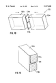
FIG. 1A is a cross-sectional view of a first embodiment of the present invention;
FIGS. 1B and 1C are illustrations of the manufacturing process for the cell body;
FIG. 2A is a ray diagram of refraction and reflection processes of a light ray incident on a surface of a transparent body;
FIGS. 2B and 2C are ray diagrams of the difference between specular and diffuse reflection at the cell wall;
FIG. 3 is a graph of reflectance versus incident angle at a surface of a transparent body;
FIG. 4 is a cross-sectional view of a second embodiment of the present invention;
FIG. 5 is a cross-sectional view of a third embodiment of the present invention;
FIG. 6 is an electropherogram of the bandbroadening effect due to different diameters of the capillary and channel at the junction;
FIG. 7 is an electropherogram of the gain in sensitivity achieved by the present invention.
FIGS. 8 and 9 are respectively drawings of slit and capillary arrangements used in an on column approach.
FIG. 10 is a graph of the principle detector response characteristic;
FIG. 11 is a diagram of a prior art flow cell used in liquid chromatography.
DETAILED DESCRIPTION OF THE PREFERRED EMBODIMENTS
Before the invention is described in detail, it is to be understood that this invention is not limited to the particular component parts of the devices described as such devices may vary.
It is also to be understood that the terminology used herein is for purposes of describing particular embodiments only, and is not intended to be limiting.
It is also to be understood that the same basic construction can not only be used for absorbance measurements, but also for fluorescence or Raman spectroscopy or colorimetry, with flowing or static samples.
In this specification and in the claims which follow, reference will be made to a number of terms which shall be defined to have the following meanings:
The term "liquid phase analysis" is used to refer to any analysis which is done on either small and/or macromolecular solutes in the liquid phase.
The term "liquid phase analysis" as used herein includes chromatographic separations, electrophoretic separations, and electrochromatographic separations.
The term "chromatographic process" generally refers to preferential separations of components, and includes reverse-phase, hydrophobic interaction, ion exchange, molecular sieve chromatography and like methods.
The term "electrophoretic separation" refers to the migration of particles or macromolecules having a net electric charge where the migration is influenced by an electric field. Therefore "electrophoretic separation" includes separations performed in columns packed with gels (such as poly-acrylamide, agarose and combinations thereof) as well as separations performed in solution.
The term "electrochromatographic separation" refers to combinations of electrophoretic and chromatographic techniques.
In the following a preferred embodiment of the present invention is described.
A flow cell according to the preferred embodiment is used for analysing small liquid sample volumes, i.e. volumes as small as 3-15 nl.
This is accomplished by a design that allows a high light flux through the cell, and features minimize flow disturbances to maintain high efficient separations.
FIG. 1A is a cross sectional view of a photometric flow apparatus 100 according to an embodiment of the present invention.
The photometric flow cell 100 comprises a cell body 102 of a non-transparent material. A first transparent window 104 is arranged adjacent to a first surface of the cell body 102.
A light source 105 and/or light guiding means (not shown) such as lenses or mirrors, is arranged adjacent to the first transparent window 104 for emitting light of a predetermined wavelength or wavelength range therethrough.
A second transparent window 106 is arranged adjacent to a second surface of the cell body 102 opposite to the first surface.
A photo detector means 107 is arranged adjacent to the second transparent window 106. The photodetector means 107 can include mirrors, gratings (not shown) and photo diode arrays.
A flow channel 108 is formed inside the cell body 102. According to the embodiment shown in FIG. 1A the flow channel 108 comprises three portions 108a, 108b, 108c. The first portion 108a of the flow channel 108 is formed adjacent to the first transparent window 104 and extends substantially parallel to the first surface of the cell body 102. The second portion 108b of the flow channel 108 extends from the first surface to the second surface of the cell body 102. The third portion 108c of the flow channel 108 is formed adjacent to the second transparent window 106 and extends substantially parallel to the second surface of the cell body 102.
As can be seen from FIG. 1A the first, second and -third portion 108a-c of the flow channel 108 include junction portions 108d. These junction portions 108d connect the respective portions 108a, 108b and 108b, 108c of the flow channel 108 preferably through an angle of 45°.
It is apparent that angles other than 45° are possible for connection of the flow channel portions.
It is however possible to connect the respective junction portions 108d without any chamfer.
The transparent windows 104, 106 can be made of fused silica and may be directly fused to the cell body 102.
Holes 110 and 112 are provided in the cell 100 for accommodating the ends of an inlet capillary 114 and an outlet capillary 116. These holes 110 and 112 are preferably ultrasonically machined.
In FIG. 1A, a feature concerning the capillary/flow channel coupling in the present invention is shown.
Especially in capillary electrophoresis, it is important to minimize distortions of the electrical field at capillary/flow channel junction portions in order to maintain separation efficiency.
As shown in FIG. 1A, the inlet capillary 114 having a smaller ID (ID=Inner Diameter) than the width of the channel 108 in the cell body 102 is coupled to the cell 100. The inlet capillary 114 has a wider ID at the capillary/flow channel junction to match the diameter to the channel width.
There are different approaches possible to widen the ID of the capillary 114.
In one embodiment, the volume within the capillary is pressurized and the capillary is rotated in a gas flame until the ID of the capillary is increased to the desired extension. This might take a few seconds.
After that, the capillary is scored at the center of the cavity and an axial tension is applied. The capillary will break at the center of the cavity with a clear and rectangular edge. Thus a capillary/flow channel junction is provided having gradual curves and transitions to achieve smooth flow and avoid turbulences.
The capillaries used for microcolumn separations such as capillary electrophoresis or μ-liquid chromatography have inner diameters typically ranging from 25 to 100 μm.
The cell shown in FIG. 1A is designed for very small sample volumes. In this embodiment the flow channel of the cell has a rectangular cross-section of less than 150×150 μm and a channel length of less than 1.3 mm, resulting in a cell volume of less than 10 nl. A detection pathlenght of 1 mm results in a sensitivity up to 20 times higher than on column detection approaches using 50 μm-ID fused silica capillaries.
In one preferred embodiment, the cell body 102 is made of a non-transparent material, such as opaque black Suprasil (registered trademark) (black fused silica) available from Heraeus.
As shown in FIG. 1B the cell body 102 comprises a first and a second portion 102a and 102b. A first and a second flow channel forming part 118a and 118b are arranged between the first portion 102a and the second portion 102b of the cell body 102 such that the flow channel 108 shown in FIG. 1A is formed. The cell body 102 is formed by directly fusing together the first portion 102a of the cell body 102, the first and second flow channel forming parts 118a, 118b, and the second portion 102b of the cell body.
Such a process is known in the art and often used for cuvettes and the like.
FIG. 1C is a cross sectional view of the cell body 102, showing the flow channel forming parts 118a and 118b and the resulting flow channel 108 in more detail.
The provision of a cell body 102 being non-transparent has a significant advantage in that the occurrence of stray light through the cell wall is prevented.
As already outlined above, this stray light is a known inherent problem in prior art detectors using on column detection or cells with transparent walls. It reduces the linearity of detector and also reduces the effective pathlength and thus the sensitivity.
In a non-transparent cell body the cell output defines a clear aperture which is advantageous if the cell is used for example in a diode array detector.
Before the parts shown in FIGS. 1B and 1C are fused together, the parts are machined and polished to get an even and flat surface. A surface roughness in the order of less than 0.5 μm is to be achieved as this is a requirement for a successive fusing process.
The provision of a superior surface quality is however also a requirement for another essential feature of the present invention. The superior surface quality causes light rays entering the cell and striking the cell wall to be reflected at the same angle as they are incident on this wall.
This feature is illustrated in more detail in FIGS. 2A, 2B and 2C.
As shown in FIG. 2A, a first part 200 of an incident light ray 202 on a transmitting medium 204, such as quartz, is refracted into the material 204, while a second part 206 of the incident light 202 is reflected.
While the refraction angle Θt depends on the refractive index n of the media through which the incident and refracted rays propagate, such as air and quartz, the reflection angle Θr always equals the angle of incidence Θi.
The amount of light reflected depends on the incident angle Θi.
FIGS. 2B and 2C are respectively drawings of ray paths occurring for diffuse and the specular reflection.
As can be seen from FIG. 2B, the surface of a medium 208 has irregularities, wherein these irregularities are large when compared to the wavelength of the incident light 210. These irregularities lead to a diffuse reflection of the incident light 210.
From FIG. 2C medium 212 has a smooth surface having irregularities that are small compared to the wavelength of the reflected light. This is prerequisite for specular reflection of the incident light 214.
FIG. 3 is a graph of the reflectance versus incident angle, assuming water (n=1.33) as incident media and quartz (n=1.5) as material into which the light is refracted.
From the graph the amount of reflected light increases dramatically at incident angles higher than 80 degrees and is almost zero for angles less than 60 degrees.
The dependency of the reflectance from the incident angle can be expressed by the following equations: ##EQU3## The present invention makes use of this effect to achieve a high light throughput through the cell, to thus keep the photometric noise low. The channel walls are kept even and polished to achieve specular reflection, thus guiding the light through the cell. For UV/Vis detection using conventional light sources, the illumination of small volumes requires fast optics. Since the channel dimensions are small and the channel is narrow, it is important to guide light that enters the cell towards the detector and not to loose it by diffuse reflection at the cell wall.
According to a second embodiment shown in FIG. 4, the photometric flow cell 100 further comprises a first capillary support means 120 supporting the inlet capillary 114 and a second capillary support means 122 supporting the outlet capillary 116.
The capillaries 114, 116 can be fixed to the cell using a glue 124, or a plastic fittings which are commonly employed to seal the capillary to the cell.
It is apparent that other means for guiding and attaching the capillaries can be used.
FIG. 5 is a drawing of a third embodiment of the present invention. The flow cell 500 shown in FIG. 5 corresponds partially to the first and second embodiment, so that the description of similar parts having the same reference signs as in the first and second embodiment is omitted.
Contrary to the first and second embodiments the flow cell 500 shown in FIG. 5 does not comprise a first and a second transparent window.
The flow cell 500 comprises a first non-transparent portion 504 arranged adjacent to the first surface of the cell body 102 and a second non-transparent portion 506 arranged adjacent to the second surface of the cell body 102.
According to the third embodiment the light is guided from a light source (not shown) to the cell body 102 by an optical input waveguide 510.
Preferably the light guided to the flow cell 102 by the input waveguide 510 travelling through the channel 108 is collected by an optical output fibre 512 which guides the light to any kind of optical detector such as a photomultilier, a diode, a spectrometer, etc.
Preferably the non-transparent portions 504, 506 are formed by Black Suprasil (registered trademark).
It is to be noted that the fibres 510, 512 are preferably in direct communication with the flow channel 108.
The embodiment shown in FIG. 5 is advantageous in that it allows remote measurement and/or a thermal isolation of the liquid guiding means in a liquid phase analysis instrument.
FIG. 6. is an electropherogram where a capillary with (microcell #1) and one without (microcell #2) expanded ID at the capillary/flow channel junction was used.
The electropherogram was recorded under the following conditions:
Buffer: Borate 20 mM pH8
Sample: p-hydroxyacetophenone (100 μM in water)
Cassette temperature: 25° C.
Injection: 100 mbarsec
Detection: 325 nm, 4 nm BW, 0,2 sec Rt.
Voltage: 25 kV
Capillary length: 56 cm
It can be clearly seen that the capillary having the straight end shows more peak tailing and thus lower efficiency.
In FIG. 7 a graph is shown illustrating the gain in sensitivity readily achieved in an electrophoretic separation using a microcell according to the present invention.
The electropherogram was recorded under the following conditions:
Buffer: Borate 20 mM pH8
Sample: p-hydroxyacetophenone (1 μM in water)
Cassette temperature: 25° C.
Injection: 200 mbarsec, postinj. 100 mbarsec
Detection: 325 nm, 4 nm BW, 0,2 sec Rt.
Voltage: 25 kV
Capillary length: 56 cm
The cell according to the present invention was compared to the most sensitive on column detection approach that is readily available for capillary electrophoresis, using a capillary with 75 μm ID that is expanded three times at the point of detection.
The present invention offers unprecedented sensitivity in detection for liquid phase analysis of microscopic samples.
It has to be noted that the present invention is not limited to the transparent windows as described in the first and in the second embodiment or to the light input and light output waveguides. Other means for inputting the light into the flow cell and for outputting the light from the flow cell to a detector means can be used.
Although the present invention has been described in detail with reference to a particular preferred embodiment, persons processing ordinary skill in the art to which this invention pertains will appreciate that various modifications and enhancements may be made without departing from the spirit and scope of the claims that follow.

Claims (24)

I claim:
1. Photometric apparatus for small sample volumes comprising:
a cell body;
a light input means arranged adjacent a first surface of the cell body;
a light source for emitting light of predetermined wavelength or wavelength range through the light input means;
a light output means arranged adjacent a second surface of the cell body opposite to the first surface;
a light detector arranged adjacent the light output means; and
a flow channel formed in the cell body; wherein surfaces of the walls of the channel have a roughness smaller than the predetermined wavelength or all wavelengths of the wavelength range of the source.
2. Apparatus according to claim 1, wherein the light input means comprises an optical input waveguide; and wherein the light output means comprises an optical output waveguide.
3. Apparatus according to claim 1, wherein the light input means comprises a first transparent window; and wherein the light output means comprises a second transparent window.
4. Apparatus according to claim 1, wherein the cell body is formed of non-transparent material.
5. Apparatus according to claim 3, wherein the flow channel comprises:
a first portion formed adjacent to the first transparent window and extending substantially parallel to the first surface of the cell body;
a second portion extending from the first surface to the second surface of the cell body; and
a third portion formed adjacent to the second transparent window and extending substantially parallel to the second surface of the cell body.
6. Apparatus according to claim 1, comprising an inlet capillary and an outlet capillary in fluid connection with the flow channel.
7. Apparatus according to claim 1, wherein at least one of an inlet capillary and an output capillary has an expanded inner diameter at the capillary/flow channel junction.
8. Apparatus according to claim 6, comprising capillary support structure attached to the cell body for supporting the inlet and the outlet capillary.
9. Apparatus according to claim 8, wherein the inlet capillary and the outlet capillary are secured to the capillary support structure by glue or plastic fittings.
10. Apparatus according to claim 1, wherein the cell body comprises a first and a second portion, a first and a second flow channel forming part arranged between the first portion and the second portion of the cell body, wherein the cell body is formed by directly fusing together the first portion of the cell body, the first and second flow channels respectively forming parts, and the second portion.
11. Apparatus according to claim 4, wherein the flow channel includes junction portions connecting the flow channel portions under an angle of 45°.
12. Apparatus according to claim 1, wherein the flow channel has a rectangular cross-section of less than 150×150 μm and a channel length of less than 1.5 mm.
13. Apparatus according to claim 1, wherein the flow channel has a rectangular cross-section of less than 150×150 μm, a channel length of less than 1.5 mm and a total volume of less than 10 nl.
14. Apparatus according to claim 3, wherein the transparent windows are made of fused silica.
15. The photometric apparatus of claim 1 wherein the channel includes separate individual parts that are polished before being assembled to achieve the stated roughness.
16. A method of making a flow cell for use in liquid chromatography, the cell in use being responsive to optical energy having a predetermined wavelength or wavelength range, comprising determining the wavelength or wavelength range, forming in the cell an elongated flow channel for the liquid, the flow channel being arranged so in use of the cell the optical energy propagates and the liquid flows along the flow channel longitudinal axis, and machining and polishing the channel wall so the wall surface roughness has a value less than the determined wavelength or all wavelengths of the wavelength range of the source.
17. The method of claim 16, further including forming the channel from separate individual parts that are polished to achieve the stated channel wall surface roughness, the individual parts being polished to achieve the stated roughness prior to being assembled to form the channel.
18. Apparatus for use in spectroscopy analysis of small samples in liquid solution comprising
a source of optical radiation having a predetermined wavelength or range of wavelengths, radiation from the source being directed in a predetermined direction,
an optical detector for radiation from the source,
a photometric flow cell including first and second members forming a cell body, the cell body including a flow channel for the liquid, the flow channel including a first component extending in the predetermined direction, the first component of the flow channel being defined by a slit between opposed edges of first and second plates bonded to the cell body and opposed faces of the first and second members, the edges of the plates and the opposed faces defining the first component of the flow channel having a roughness smaller than the predetermined wavelength or all wavelengths of the wavelength range of the source,
first and second windows transparent to optical radiation from the source bonded to the cell body so that optical radiation from the source propagates through the first window, thence through the slit, thence through the second window and thence to the optical detector,
the channel including second and third components connected to opposite sides of the slit for respectively supplying the liquid solution to the slit and removing the liquid solution from the slit.
19. Apparatus according to claim 18, wherein the second channel component includes a first passage between the first plate and the first window and the third channel component includes a second passage between the second plate and the second window.
20. Apparatus according to claim 18, wherein the slit has only planar faces.
21. Apparatus according to claim 18, wherein the slit has a cross-sectional area no greater than 0.25 square millimeters.
22. Apparatus according to claim 18, wherein the cell body and the plates are opaque to optical radiation of the source.
23. A method of making a photometric flow cell for use in spectroscopy analysis of small samples in liquid solution, the spectroscopy analysis being performed with an optical radiation source having a predetermined wavelength or range of wavelengths, the cell including first and second members having planar faces and a slit forming a component of a flow channel for the liquid sample, the method comprising polishing first and second edges of first and second plates so the edges have a roughness less than the predetermined wavelength or all wavelengths of the wavelength range of the source, then bonding faces of the plates to planar faces of the first and second members to form the slit of the flow channel for the liquid solution, then bonding windows transparent to the optical radiation to opposite faces of the members substantially at right angles to the flow direction of the liquid solution through the slit.
24. A method according to claim 23, wherein the plates are bonded to the members so there is (a) a first set back of another edge of the first plate from a face of the first window and a second set back of a further edge of the second plate from a face of the second window, and (b) the another and further edges are substantially transverse to the flow direction of the liquid solution through the slit, and (c) a first passage in the flow channel is formed between the another edge and the first window and a second passage in the flow channel is formed between the further edge and the second window.
US08/709,017 1995-09-06 1996-09-06 Photometric flow apparatus for small sample volumes and method of making same Expired - Lifetime US5917606A (en)

Applications Claiming Priority (2)

Application Number Priority Date Filing Date Title
EP95113947 1995-09-06
EP95113947A EP0762119B1 (en) 1995-09-06 1995-09-06 Photometric flow apparatus for small sample volumes

Publications (1)

Publication Number Publication Date
US5917606A true US5917606A (en) 1999-06-29

Family

ID=8219582

Family Applications (1)

Application Number Title Priority Date Filing Date
US08/709,017 Expired - Lifetime US5917606A (en) 1995-09-06 1996-09-06 Photometric flow apparatus for small sample volumes and method of making same

Country Status (4)

Country Link
US (1) US5917606A (en)
EP (1) EP0762119B1 (en)
JP (1) JPH09170981A (en)
DE (1) DE69524405T2 (en)

Cited By (28)

* Cited by examiner, † Cited by third party
Publication number Priority date Publication date Assignee Title
WO2003027028A1 (en) * 2001-09-28 2003-04-03 Applera Corporation Multi-capillary array electrophoresis device
US20030110840A1 (en) * 2001-07-24 2003-06-19 Arriaga Edgar A. Systems and methods for detecting a particle
US6636314B1 (en) * 1998-03-26 2003-10-21 Antek Instruments, L.P. Apparatus and methods for improving fluorescence detectors
US20030226756A1 (en) * 2001-09-28 2003-12-11 Ryoji Inaba Multi-capillary array electrophoresis device
US6678051B2 (en) 2001-01-18 2004-01-13 Systec, Inc. Flow cells utilizing photometric techniques
US20040086216A1 (en) * 2002-10-31 2004-05-06 Elster Jennifer L. Fiber-optic flow cell and method relating thereto
EP1563279A1 (en) * 2002-11-12 2005-08-17 Varian Australia Pty. Ltd. Flow through cell for optical spectroscopy
US20060094004A1 (en) * 2004-10-28 2006-05-04 Akihisa Nakajima Micro-reactor, biological material inspection device, and microanalysis system
US7050660B2 (en) 2003-04-07 2006-05-23 Eksigent Technologies Llc Microfluidic detection device having reduced dispersion and method for making same
US20060139632A1 (en) * 2004-12-28 2006-06-29 Yuri Gerner Fluid analysis apparatus
US7251026B2 (en) 2001-03-02 2007-07-31 Waters Investments Limited Fluorescence detector geometry
US7259840B1 (en) 2004-12-28 2007-08-21 Systec, Llc Fluid analysis apparatus
US20070240773A1 (en) * 2004-11-25 2007-10-18 Hans-Peter Zimmermann Methods and devices for high throughput fluid delivery
US20070263207A1 (en) * 2004-08-26 2007-11-15 The Governmen Of The U.S.A., As Represented By The Secretary, Dept. Of Health And Human Services, Flow-through, inlet-gas-temperature-controlled, solvent-resistant, thermal-expansion compensated cell for light spectroscopy
US20080183418A1 (en) * 2007-01-26 2008-07-31 Palo Alto Research Center Incorporated Method and system for evaluation of signals received from spatially modulated excitation and emission to accurately determine particle positions and distances
US7419576B1 (en) * 1999-10-12 2008-09-02 Minolta Co., Ltd. Analyzing apparatus
US20080302665A1 (en) * 2002-12-12 2008-12-11 Syozo Kasai Capillary array apparatus, method of manufacturing the same, and electrophoresis analysis method
US7545490B1 (en) * 2006-09-26 2009-06-09 Itt Manufacturing Enterprises, Inc. Microscope flow cell apparatus for raman analysis of a liquid
DE102009025073A1 (en) * 2009-06-16 2010-12-30 Fraunhofer-Gesellschaft zur Förderung der angewandten Forschung e.V. Optical sensor has channel with opposite side panels which are connected by base, where optical fiber is formed along opposite side panels and along base, so that field generates light in channel by passing to optical fiber
US20100327182A1 (en) * 2008-02-14 2010-12-30 Starna Scientific Limited Fluorescence measurement cell
US20110141466A1 (en) * 2009-12-16 2011-06-16 Gunnar Magnusson Miniature flow-through cuvette and spectrophotometer containing the same
US20110222062A1 (en) * 2008-02-01 2011-09-15 Palo Alto Research Center Incorporated Analyzers with time variation based on color-coded spatial modulation
US8723140B2 (en) 2011-08-09 2014-05-13 Palo Alto Research Center Incorporated Particle analyzer with spatial modulation and long lifetime bioprobes
US8821799B2 (en) 2007-01-26 2014-09-02 Palo Alto Research Center Incorporated Method and system implementing spatially modulated excitation or emission for particle characterization with enhanced sensitivity
US9029800B2 (en) 2011-08-09 2015-05-12 Palo Alto Research Center Incorporated Compact analyzer with spatial modulation and multiple intensity modulated excitation sources
US9541532B2 (en) 2013-08-23 2017-01-10 SunChrom Wissenschaftliche Geräte GmbH UV/Vis HPLC photometer
US10451593B2 (en) * 2016-08-04 2019-10-22 Aa Holdings, Ltd. Detection system and method with nanostructure flow cell
EP3617702A1 (en) * 2018-08-30 2020-03-04 KNAUER Wissenschaftliche Geräte GmbH A combined uv/vis-absorption and conductivity flow cell for liquid chromatography

Families Citing this family (10)

* Cited by examiner, † Cited by third party
Publication number Priority date Publication date Assignee Title
US6224830B1 (en) 1998-01-30 2001-05-01 The Governors Of The University Of Alberta Absorbance cell for microfluid devices
US6188813B1 (en) * 1999-02-10 2001-02-13 Waters Investments Limited Flow cell, analyte measurement apparatus and methods related thereto
US7294839B2 (en) * 2002-10-08 2007-11-13 Ric Investements, Inc. Low volume sample cell and gas monitoring system using same
JP2006078414A (en) * 2004-09-13 2006-03-23 Alps Electric Co Ltd Plate for examination
US7386199B2 (en) * 2005-12-22 2008-06-10 Palo Alto Research Center Incorporated Providing light to channels or portions
JP4781827B2 (en) * 2006-01-24 2011-09-28 シャープ株式会社 Analysis method and analyzer
CN100419406C (en) * 2006-03-31 2008-09-17 洪陵成 Flow-thru tank of flow photometric analyzing
GB2473787A (en) 2008-08-07 2011-03-23 Agilent Technologies Inc Multi-wavelength light source
JP5854621B2 (en) * 2011-04-07 2016-02-09 株式会社日立ハイテクノロジーズ Long optical path length flow cell
JP6551609B2 (en) * 2016-08-25 2019-07-31 株式会社島津製作所 Flow cell

Citations (10)

* Cited by examiner, † Cited by third party
Publication number Priority date Publication date Assignee Title
US3751173A (en) * 1972-08-24 1973-08-07 Micromedic Systems Inc Flowthrough cuvette
US4575424A (en) * 1984-03-01 1986-03-11 Isco, Inc. Chromatographic flow cell and method of making it
EP0266769A2 (en) * 1986-11-07 1988-05-11 Hitachi, Ltd. Flow cell for photometer
EP0396163A2 (en) * 1989-04-14 1990-11-07 Kontron Instruments Holding N.V. Capillary flow cell
US5061361A (en) * 1989-03-06 1991-10-29 Hewlett-Packard Company Capillary zone electrophoresis cell system
EP0488947A1 (en) * 1990-11-26 1992-06-03 Ciba-Geigy Ag Detector cell
US5171995A (en) * 1990-09-28 1992-12-15 Bruker Analytische Mebtechnik Gmbh Sample holder for optical spectrometer and method for taking a spectrum
EP0523680A2 (en) * 1991-07-17 1993-01-20 Waters Investments Limited Photometric apparatus
US5273633A (en) * 1992-07-10 1993-12-28 Tiansong Wang Capillary multireflective cell
US5493405A (en) * 1993-07-19 1996-02-20 Optiglass Limited Spectrophotometer cell having an intermediate wall member and an integral lens

Family Cites Families (1)

* Cited by examiner, † Cited by third party
Publication number Priority date Publication date Assignee Title
US3783276A (en) * 1972-06-05 1974-01-01 Instrumentation Specialties Co Dual beam optical system

Patent Citations (11)

* Cited by examiner, † Cited by third party
Publication number Priority date Publication date Assignee Title
US3751173A (en) * 1972-08-24 1973-08-07 Micromedic Systems Inc Flowthrough cuvette
US4575424A (en) * 1984-03-01 1986-03-11 Isco, Inc. Chromatographic flow cell and method of making it
US5141548A (en) * 1986-04-14 1992-08-25 Kontron Instruments Holding Nv Method of manufacturing a capillary flow cell
EP0266769A2 (en) * 1986-11-07 1988-05-11 Hitachi, Ltd. Flow cell for photometer
US5061361A (en) * 1989-03-06 1991-10-29 Hewlett-Packard Company Capillary zone electrophoresis cell system
EP0396163A2 (en) * 1989-04-14 1990-11-07 Kontron Instruments Holding N.V. Capillary flow cell
US5171995A (en) * 1990-09-28 1992-12-15 Bruker Analytische Mebtechnik Gmbh Sample holder for optical spectrometer and method for taking a spectrum
EP0488947A1 (en) * 1990-11-26 1992-06-03 Ciba-Geigy Ag Detector cell
EP0523680A2 (en) * 1991-07-17 1993-01-20 Waters Investments Limited Photometric apparatus
US5273633A (en) * 1992-07-10 1993-12-28 Tiansong Wang Capillary multireflective cell
US5493405A (en) * 1993-07-19 1996-02-20 Optiglass Limited Spectrophotometer cell having an intermediate wall member and an integral lens

Non-Patent Citations (8)

* Cited by examiner, † Cited by third party
Title
Ahmad A. Abbas, et al., "Optical properties of axial-illumination flow cells for simultaneous absorbance-fluorescence detection in micro liquid chromatography," Journal of Chromatography, vol. 691, pp. 37-53.
Ahmad A. Abbas, et al., Optical properties of axial illumination flow cells for simultaneous absorbance fluorescence detection in micro liquid chromatography, Journal of Chromatography , vol. 691, pp. 37 53. *
James W. Jorgenson, et al., "High-resolution separations based on electrophoresis and electroosmosis," Journal of Chromatography, vol. 218, pp. 209-216.
James W. Jorgenson, et al., "Zone Electrophoresis in Open Tubular Glass Capillaries," Analytical Chemistry, Jul. 1981, pp. 1298-1302.
James W. Jorgenson, et al., High resolution separations based on electrophoresis and electroosmosis, Journal of Chromatography , vol. 218, pp. 209 216. *
James W. Jorgenson, et al., Zone Electrophoresis in Open Tubular Glass Capillaries, Analytical Chemistry , Jul. 1981, pp. 1298 1302. *
Xiaobing XI, et al., "Axial-Beam On-Column Absorption Detection for Open Tubular Capillary Liquid Chromatography," Analytical Chemistry, Aug. 1, 1990, pp. 1580-1585.
Xiaobing XI, et al., Axial Beam On Column Absorption Detection for Open Tubular Capillary Liquid Chromatography, Analytical Chemistry , Aug. 1, 1990, pp. 1580 1585. *

Cited By (49)

* Cited by examiner, † Cited by third party
Publication number Priority date Publication date Assignee Title
US6636314B1 (en) * 1998-03-26 2003-10-21 Antek Instruments, L.P. Apparatus and methods for improving fluorescence detectors
US7419576B1 (en) * 1999-10-12 2008-09-02 Minolta Co., Ltd. Analyzing apparatus
US6734961B2 (en) 2001-01-18 2004-05-11 Systec, Inc. Flow cells utilizing photometric techniques
US6678051B2 (en) 2001-01-18 2004-01-13 Systec, Inc. Flow cells utilizing photometric techniques
US7251026B2 (en) 2001-03-02 2007-07-31 Waters Investments Limited Fluorescence detector geometry
US20030110840A1 (en) * 2001-07-24 2003-06-19 Arriaga Edgar A. Systems and methods for detecting a particle
US8043493B2 (en) 2001-09-28 2011-10-25 Hitachi, Ltd. Multi-capillary array electrophoresis device
WO2003027028A1 (en) * 2001-09-28 2003-04-03 Applera Corporation Multi-capillary array electrophoresis device
US20030226756A1 (en) * 2001-09-28 2003-12-11 Ryoji Inaba Multi-capillary array electrophoresis device
US8246806B2 (en) 2001-09-28 2012-08-21 Applera Corporation Multi-capillary array electrophoresis device
US20070158195A1 (en) * 2001-09-28 2007-07-12 Ryoji Inaba Multi-capillary array electrophoresis device
US7250098B2 (en) 2001-09-28 2007-07-31 Applera Corporation Multi-capillary array electrophoresis device
US20070175761A1 (en) * 2001-09-28 2007-08-02 Ryoji Inaba Multi-capillary array electrophoresis device
US6987897B2 (en) * 2002-10-31 2006-01-17 Luna Innovations Incorporated Fiber-optic flow cell and method relating thereto
US20040086216A1 (en) * 2002-10-31 2004-05-06 Elster Jennifer L. Fiber-optic flow cell and method relating thereto
EP1563279A4 (en) * 2002-11-12 2010-01-27 Varian Australia Flow through cell for optical spectroscopy
EP1563279A1 (en) * 2002-11-12 2005-08-17 Varian Australia Pty. Ltd. Flow through cell for optical spectroscopy
US20080302665A1 (en) * 2002-12-12 2008-12-11 Syozo Kasai Capillary array apparatus, method of manufacturing the same, and electrophoresis analysis method
US20070104408A1 (en) * 2003-04-07 2007-05-10 Cyr Douglas R Microfluidic detection device having reduced dispersion and method for making same
US7925125B2 (en) 2003-04-07 2011-04-12 Dh Technologies Development Pte. Ltd. Microfluidic detection device having reduced dispersion and method for making same
US7336860B2 (en) 2003-04-07 2008-02-26 Eksigent Technologies, Llc Microfluidic detection device having reduced dispersion and method for making same
US7050660B2 (en) 2003-04-07 2006-05-23 Eksigent Technologies Llc Microfluidic detection device having reduced dispersion and method for making same
US20080216951A1 (en) * 2003-04-07 2008-09-11 Cyr Douglas R Microfluidic Detection Device Having Reduced Dispersion And Method For Making Same
US20070263207A1 (en) * 2004-08-26 2007-11-15 The Governmen Of The U.S.A., As Represented By The Secretary, Dept. Of Health And Human Services, Flow-through, inlet-gas-temperature-controlled, solvent-resistant, thermal-expansion compensated cell for light spectroscopy
US7894055B2 (en) * 2004-08-26 2011-02-22 The United States Of America As Represented By The Department Of Health And Human Services Flow-through, inlet-gas-temperature-controlled, solvent-resistant, thermal-expansion compensated cell for light spectroscopy
US20060094004A1 (en) * 2004-10-28 2006-05-04 Akihisa Nakajima Micro-reactor, biological material inspection device, and microanalysis system
US20070240773A1 (en) * 2004-11-25 2007-10-18 Hans-Peter Zimmermann Methods and devices for high throughput fluid delivery
US7259840B1 (en) 2004-12-28 2007-08-21 Systec, Llc Fluid analysis apparatus
US7808619B2 (en) 2004-12-28 2010-10-05 Waters Technologies Corporation System for assembling a fluid analysis apparatus
US20080024775A1 (en) * 2004-12-28 2008-01-31 Yuri Gerner Fluid analysis apparatus
US7298472B2 (en) 2004-12-28 2007-11-20 Rheodyne, Llc Fluid analysis apparatus
US20060139632A1 (en) * 2004-12-28 2006-06-29 Yuri Gerner Fluid analysis apparatus
US7545490B1 (en) * 2006-09-26 2009-06-09 Itt Manufacturing Enterprises, Inc. Microscope flow cell apparatus for raman analysis of a liquid
US9638637B2 (en) 2007-01-26 2017-05-02 Palo Alto Research Center Incorporated Method and system implementing spatially modulated excitation or emission for particle characterization with enhanced sensitivity
US9164037B2 (en) 2007-01-26 2015-10-20 Palo Alto Research Center Incorporated Method and system for evaluation of signals received from spatially modulated excitation and emission to accurately determine particle positions and distances
US20080183418A1 (en) * 2007-01-26 2008-07-31 Palo Alto Research Center Incorporated Method and system for evaluation of signals received from spatially modulated excitation and emission to accurately determine particle positions and distances
US8821799B2 (en) 2007-01-26 2014-09-02 Palo Alto Research Center Incorporated Method and system implementing spatially modulated excitation or emission for particle characterization with enhanced sensitivity
US8629981B2 (en) 2008-02-01 2014-01-14 Palo Alto Research Center Incorporated Analyzers with time variation based on color-coded spatial modulation
US20110222062A1 (en) * 2008-02-01 2011-09-15 Palo Alto Research Center Incorporated Analyzers with time variation based on color-coded spatial modulation
US8357916B2 (en) * 2008-02-14 2013-01-22 Starna Scientific Limited Fluorescence measurement cell
US20100327182A1 (en) * 2008-02-14 2010-12-30 Starna Scientific Limited Fluorescence measurement cell
DE102009025073A1 (en) * 2009-06-16 2010-12-30 Fraunhofer-Gesellschaft zur Förderung der angewandten Forschung e.V. Optical sensor has channel with opposite side panels which are connected by base, where optical fiber is formed along opposite side panels and along base, so that field generates light in channel by passing to optical fiber
US8502969B2 (en) * 2009-12-16 2013-08-06 Boule Medical Ab Miniature flow-through cuvette and spectrophotometer containing the same
US20110141466A1 (en) * 2009-12-16 2011-06-16 Gunnar Magnusson Miniature flow-through cuvette and spectrophotometer containing the same
US8723140B2 (en) 2011-08-09 2014-05-13 Palo Alto Research Center Incorporated Particle analyzer with spatial modulation and long lifetime bioprobes
US9029800B2 (en) 2011-08-09 2015-05-12 Palo Alto Research Center Incorporated Compact analyzer with spatial modulation and multiple intensity modulated excitation sources
US9541532B2 (en) 2013-08-23 2017-01-10 SunChrom Wissenschaftliche Geräte GmbH UV/Vis HPLC photometer
US10451593B2 (en) * 2016-08-04 2019-10-22 Aa Holdings, Ltd. Detection system and method with nanostructure flow cell
EP3617702A1 (en) * 2018-08-30 2020-03-04 KNAUER Wissenschaftliche Geräte GmbH A combined uv/vis-absorption and conductivity flow cell for liquid chromatography

Also Published As

Publication number Publication date
JPH09170981A (en) 1997-06-30
DE69524405T2 (en) 2002-05-23
DE69524405D1 (en) 2002-01-17
EP0762119A1 (en) 1997-03-12
EP0762119B1 (en) 2001-12-05

Similar Documents

Publication Publication Date Title
US5917606A (en) Photometric flow apparatus for small sample volumes and method of making same
JP3657900B2 (en) Fiber-coupled liquid sample analyzer with liquid flow cell
US5444807A (en) Micro chemical analysis employing flow through detectors
US4747687A (en) Ball cell windows for spectrophotometers
EP0616211B1 (en) Optical detection arrangement for small volume chemical analysis of fluid samples
JP3260431B2 (en) Flow cell fabrication method
US7336860B2 (en) Microfluidic detection device having reduced dispersion and method for making same
US6188813B1 (en) Flow cell, analyte measurement apparatus and methods related thereto
US4088407A (en) High pressure fluorescence flow-through cuvette
US5414508A (en) Optical cell and optical detection systems light absorption
EP1564541B1 (en) Dual pathlength system for light absorbance detection
Verpoorte et al. A silicon flow cell for optical detection in miniaturized total chemical analysis systems
US5599503A (en) Detector cell
US20050257885A1 (en) Capillary multi-channel optical flow cell
US5423513A (en) Method of and a capillary flow cell for analysing fluid samples
US4006990A (en) Convergent light illuminated flow cell for liquid chromatography
US5239360A (en) Lens for capillary electrophoresis and chromatography
US4475813A (en) Divergent light optical systems for liquid chromatography
EP1229322B1 (en) Cell for analyzing fluid and analyzing apparatus using the same
US7005090B2 (en) Method for manufacturing a flow cell
US3975104A (en) Convergent light illuminated flow cell for liquid chromatography
US5493405A (en) Spectrophotometer cell having an intermediate wall member and an integral lens
US4501969A (en) Photometric apparatus and process
US4555936A (en) Multifunctional detector
WO2006127590A2 (en) Microfluidic detection cell for stimulated radiation measurements

Legal Events

Date Code Title Description
AS Assignment

Owner name: HEWLETT-PACKARD COMPANY, CALIFORNIA

Free format text: ASSIGNMENT OF ASSIGNORS INTEREST;ASSIGNOR:HEWLETT-PACKARD GMBH;REEL/FRAME:008551/0101

Effective date: 19961104

STCF Information on status: patent grant

Free format text: PATENTED CASE

AS Assignment

Owner name: HEWLETT-PACKARD COMPANY, A DELAWARE CORPORATION, C

Free format text: MERGER;ASSIGNOR:HEWLETT-PACKARD COMPANY, A CALIFORNIA CORPORATION;REEL/FRAME:010841/0649

Effective date: 19980520

AS Assignment

Owner name: AGILENT TECHNOLOGIES INC, CALIFORNIA

Free format text: ASSIGNMENT OF ASSIGNORS INTEREST;ASSIGNOR:HEWLETT-PACKARD COMPANY;REEL/FRAME:010977/0540

Effective date: 19991101

FPAY Fee payment

Year of fee payment: 4

FPAY Fee payment

Year of fee payment: 8

FPAY Fee payment

Year of fee payment: 12