US5926366A - Tab and slot disk drive vibration reduction structure - Google Patents
Tab and slot disk drive vibration reduction structure Download PDFInfo
- Publication number
- US5926366A US5926366A US08/749,465 US74946596A US5926366A US 5926366 A US5926366 A US 5926366A US 74946596 A US74946596 A US 74946596A US 5926366 A US5926366 A US 5926366A
- Authority
- US
- United States
- Prior art keywords
- housing
- shelf
- tab
- slot
- disk drive
- Prior art date
- Legal status (The legal status is an assumption and is not a legal conclusion. Google has not performed a legal analysis and makes no representation as to the accuracy of the status listed.)
- Expired - Lifetime
Links
- 238000003780 insertion Methods 0.000 description 11
- 230000037431 insertion Effects 0.000 description 11
- 238000004891 communication Methods 0.000 description 9
- 230000000712 assembly Effects 0.000 description 7
- 238000000429 assembly Methods 0.000 description 7
- 238000013016 damping Methods 0.000 description 3
- 238000000605 extraction Methods 0.000 description 3
- 230000001627 detrimental effect Effects 0.000 description 2
- 230000003993 interaction Effects 0.000 description 2
- 239000000463 material Substances 0.000 description 2
- 230000007246 mechanism Effects 0.000 description 2
- 230000000116 mitigating effect Effects 0.000 description 2
- 230000005540 biological transmission Effects 0.000 description 1
- 230000015556 catabolic process Effects 0.000 description 1
- 238000006243 chemical reaction Methods 0.000 description 1
- 238000006731 degradation reaction Methods 0.000 description 1
- 238000009434 installation Methods 0.000 description 1
- 230000010354 integration Effects 0.000 description 1
- 238000012423 maintenance Methods 0.000 description 1
- 238000004519 manufacturing process Methods 0.000 description 1
- 230000013011 mating Effects 0.000 description 1
- 230000005055 memory storage Effects 0.000 description 1
- 239000002184 metal Substances 0.000 description 1
Images


Classifications
-
- H—ELECTRICITY
- H05—ELECTRIC TECHNIQUES NOT OTHERWISE PROVIDED FOR
- H05K—PRINTED CIRCUITS; CASINGS OR CONSTRUCTIONAL DETAILS OF ELECTRIC APPARATUS; MANUFACTURE OF ASSEMBLAGES OF ELECTRICAL COMPONENTS
- H05K7/00—Constructional details common to different types of electric apparatus
- H05K7/14—Mounting supporting structure in casing or on frame or rack
- H05K7/1422—Printed circuit boards receptacles, e.g. stacked structures, electronic circuit modules or box like frames
- H05K7/1424—Card cages
- H05K7/1425—Card cages of standardised dimensions, e.g. 19"-subrack
-
- G—PHYSICS
- G11—INFORMATION STORAGE
- G11B—INFORMATION STORAGE BASED ON RELATIVE MOVEMENT BETWEEN RECORD CARRIER AND TRANSDUCER
- G11B33/00—Constructional parts, details or accessories not provided for in the other groups of this subclass
- G11B33/02—Cabinets; Cases; Stands; Disposition of apparatus therein or thereon
- G11B33/08—Insulation or absorption of undesired vibrations or sounds
Definitions
- the present invention relates to disk drive storage mechanisms, and more particularly relates to a new and improved structure for attaching a disk drive housing to a rack which reduces vibration of the disk drive.
- the minimization of vibration in disk drives assemblies is the source of much continuing effort in the disk drive industry.
- the basic problem is how to rigidly mount a disk drive assembly in an enclosure, such as a rack system, to help minimize vibration problems, while simultaneously allowing safe, easy removal and replacement of the disk drive assembly.
- the disk drives were bolted to the enclosures and were isolated from the enclosures with bushings or grommets. This vibration damping structure worked for disk drives that were less susceptible to vibration problems than the disk drives of the present, but seriously impeded the ability to easily remove and replace the disk drive assemblies.
- Vibration causes many problems, including but not limited to increasing retry rates, which devastates system performance.
- the vibration problems are accordingly increased.
- the increase in track densities have forced an even greater burden of vibration attenuation to the systems integration level.
- Vibration arresting measures can be implemented where the rack system is mounted to the floor, where each rack is attached to the rack system, where the drive housing is attached to the shelf, and inside the drive housing itself.
- vibration can cause serious performance problems, and even permanent damage, to an individual drive or a group of drives.
- the most efficient manner of protecting the customers investment with respect to vibration attenuation directs vibration reduction efforts to the interaction of the disk drive and the shelf upon which it is positioned.
- the present invention in general terms concerns a connection structure between a disk drive housing and a rack to eliminate a source of vibration, and hence improve the performance of the disk drive.
- This invention is directed to attaching the drive housing or carrier to the rack in a rigid manner which reduces the development of vibrations due to the rattling of the housing in the rack. More particularly, this invention concerns an interference-fit tab and slot vibration reduction structure, where the tab is formed on the housing and the slot is formed on the shelf.
- the tab and slot vibration reduction structure includes a disk drive having an outer housing, the housing having a bottom surface.
- a tab extends from the bottom of the housing.
- a shelf is provided on the rack system for receiving one or a plurality of disk drive housings, and one slot is formed in a front edge of the shelf for each drive housing.
- the housing has a front surface
- the tab is spaced away from the bottom surface of the housing and extends rearwardly from the front surface.
- the slot is formed adjacent to the front edge of the shelf, and includes a recess having a top wall and opposing end walls.
- the tab engages the top wall of the recess when the disk drive housing is positioned on the shelf with the tab positioned in the slot to firmly attach the housing to the shelf.
- the top wall is a fixed beam having opposing ends, and is attached to the slot at opposing end walls, and deflects upwardly upon engagement with the tab.
- a bearing surface is formed on the undersurface of the top wall, and extends or protrudes therefrom to make contact with the tab as it is inserted into the slot.
- the interaction of the tab with the top wall of the slot specifically by the tab upwardly flexing the top wall, causes a downward force to be created on the tab, which clamps or secures the bottom of the housing to the bottom guide panel.
- the housing is thus rigidly attached to the shelf to inhibit the development of vibrations.
- Still another object of the present invention is to provide a tab and slot structure with an interference fit that reduces vibration and allows convenient extraction and replacement of drive housings from a shelf.
- FIG. 1 is a perspective view of a disk drive assembly rack system illustrating a plurality of shelves containing disk drive assembling, incorporating the tab and slot structure of the present invention.
- FIG. 2 is a perspective view of a single shelf of a disk drive assembly rack system with one disk drive assembly extracted therefrom.
- FIG. 3 is an enlarged partial perspective view similar to FIG. 2.
- FIG. 4 is an enlarged partial bottom perspective view of a disk drive assembly.
- FIG. 5 is an enlarged representative partial section taken along the line 5--5 of FIG. 2.
- FIG. 6 is an enlarged partial section taken along line 6--6 of FIG. 3.
- FIG. 7 is an enlarged partial bottom perspective view of the front edge of a bottom guide panel of a shelf.
- FIG. 8 is an enlarged section taken along line 8--8 of FIG. 6.
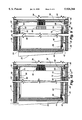
- FIG. 9 is an enlarged partial representative section of a disk drive assembly prior to full insertion in a rack system, with the left portion taken through the tab and slot structure, and the right portion taken through the guide structure.
- FIG. 10 is an enlarged partial section of a disk drive assembly prior to full insertion, taken along line 10--10 of FIG. 2, with the left portion taken through the tab and slot structure, and the right portion taken through the guide structure.
- disk drive assemblies 20 are grouped in rack systems 22 to provide high-volume centralized memory storage capability.
- the rack systems 22 are analogous to a cabinet, with several levels of shelves 24 spaced vertically from the adjacent racks. Each shelf 24 has a rectangular tube shape, with a top panel 26, a bottom panel 28, and a mid-panel 30.
- the individual disk drive assemblies 20, enclosed in drive housings 32, are positioned in the shelf 24 and typically engage the mid-panel 30 where the power and communications connectors 34 are located (FIGS. 9 and 10).
- the rack systems 22 are typically designed to allow easy access to the drive assemblies 20 for maintenance and replacement purposes. Each drive assembly 20 is able to be individually removed and replaced from the rack system 22 as necessary.
- FIGS. 1, 2 and 3 a rack system 22 incorporating the tab and slot vibration reducing structure 36 (FIG. 6) is shown.
- the vibration mitigation measures of the present invention are emphasized at the interface between the individual drive housing 32 and the shelf 24.
- Each drive housing 32 rests upright on the shelf 24 and engages the mid-panel 30 for power and communications support.
- the housing 32 is precisely positioned on the shelf 24 by a guide structure 38 to insure that the housing 32 is properly aligned with the power and communications connector 34.
- the tab and slot structure 36 of the present invention is formed at the interface of the bottom 40 of the housing 32 and the front 31 of the bottom panel 28 of the shelf 24.
- a tab 44 formed on the housing 32 inserts into a slot 46 formed on the front edge 31 of the shelf 24 to bias the housing 32 against the shelf 24.
- the slot 46 receives the tab 44 in a resilient interference fit, as described below, which deflects a portion of the slot 46 upwardly and biases the tab 44 downwardly, which in turn biases the housing 32 against the shelf 24.
- the instant invention reduces vibration by securely attaching the housing 32 to the shelf 24 to make the shelf 24 and the housing assembly 32 a continuous, rigid structure.
- the instant invention securely connects the drive housing 32 to the shelf 24, and helps the housing 32 and shelf 24 act as one rigid structure, which reduces or eliminates the generation of vibrations at the interface between the two, while allowing easy removal and replacement.
- the shelf is a rectangular tube, as defined above.
- Each panel of the shelf has an outer 33 and inner 35 layer of sheet metal, with a material 37 sandwiched in between.
- a lower or bottom guide panel 39 is attached to the bottom panel 28 in front of the mid-panel 30, and an upper guide panel 41 is attached to the top panel 26 in front of the mid-panel 30.
- the disk drive assemblies 20 are positioned between the upper 41 and lower 39 guide panels as described in detail below. Power supplies and necessary electrical components (not shown) for interfacing with the drive assemblies are positioned in the shelf 24 between the mid-panel 30 and the rear end 43 of the shelf 24.
- the lower guide panel 39 defines a plurality of lower guide grooves 50 extending between the front edge 42 of the lower guide panel 39 and the mid-panel 30, and are spaced laterally across the width of the lower guide panel 39.
- the upper guide panel 41 defines a plurality of upper guide grooves 52 extending between the front edge 54 of the upper guide panel 41 and the mid-panel 30, and are spaced laterally across the width of the upper guide panel 41.
- Each of the upper grooves 52 corresponds to and are positioned directly above a lower groove 50 (See FIG. 5).
- Each lower groove 50 extends from the front edge 42 of the lower guide panel 39 and terminates just prior to reaching the rear edge 56 of the lower guide panel.
- Each groove 50 has parallel opposing sidewalls 51a and b (See FIG. 5), is preferably approximately 0.6 inches wide, and has a recessed surface 60 spaced approximately 0.1 inches offset from the surface 53 of the lower guide panel 39.
- Each upper groove 52 extends from the front edge 54 of the upper guide panel 41 and terminates just prior to reaching the rear edge 58 of the upper guide panel.
- Each groove 52 has parallel opposing sidewalls 55a and b (See FIG. 5), is preferably approximately 0.6 inches wide, and has a recessed surface 61 spaced approximately 0.1 inches offset from the surface 57 of the upper guide panel 41.
- a flexible tongue 64 is formed in the recessed surface 60 adjacent the rear end 62 of each groove 50 in the lower guide panel 39.
- the tongue 64 is a cantilever beam having a main body 66 fixed at one end and free at the other end 68.
- the free end 68 defines a protrusion 70 having a sloped surface 72 facing upwardly and toward the front edge 42 of the shelf 28.
- the main body 66 of the flexible tongue 64 is preferably flush with the recessed surface 60, with the protrusion 70 extending upwardly.
- the top of the protrusion 70 is flat.
- the grooves 52 in the upper guide panel have corresponding tongue protrusions 74 analogous to those in the lower grooves 50.
- the housing 32 for the drive 20 has opposing sidewalls 76, 78, opposing top 80 and bottom 40 walls, and opposing front 82 and rear 84 walls.
- the rear wall 84 includes the mating connection structure 85 (FIGS. 9 and 10) to connect to the power and communication interface connector 34 on the mid-wall 30 of the shelf 24.
- the bottom wall 40 defines a continuous elongated bottom guide rail 86 that is formed along one edge of the bottom wall 40, and is approximately 0.580 inches to allow insertion into the lower guide groove 50.
- the top surface 80 of the drive housing 32 also defines an elongated and continuous top guide rail 88 (also approximately 0.580 inches) formed along one edge and coextending with the lower guide rail 86.
- the rear end 90 of the top guide rail 88 includes a spring portion 92.
- the spring portion 92 is disconnected from the top wall 80 of the housing 32, and slopes upwardly away from the top surface 80.
- the guide structure 38 acts to guide the drive housing 32 into the proper position on the shelf 24 during insertion and extraction of the drive housing 32.
- the bottom guide rail 86 is inserted into the guide groove 50 and slides therealong from the front of the shelf 24 to the rear of the shelf 24.
- the bottom guide groove 50 restrains the guide rail 86, and thus the housing 32, from becoming laterally misaligned for connection with the power and communications connector 34.
- the top guide rail 88 Upon insertion of the drive housing 32 into the shelf 24, the top guide rail 88 is positioned in the upper guide groove 52 and slides therealong from the front to the mid-panel 30.
- the upper guide groove 52 restrains the guide rail 88, and thus the housing 32, from becoming laterally misaligned for connection with the power and communications connector 34.
- the guide rails 86, 88 do not contact the bottom of the guide grooves 50, 52.
- the outer edges 88a, 86a of the upper 88 and lower 86 guide rails engage the outer edges 55a and 51a of the upper 52 and lower 50 guide grooves, as shown in FIGS. 5 and 8, to properly align the housing 32 upon insertion into the shelf 24.
- the upper 52 and lower 50 guide grooves and upper 88 and lower 86 guide rails work in conjunction with one another to guide the housing 32 to the connector 34.
- the bottom guide rail 86 engages the protrusion 70 of the bottom flexible tongue 64 as the bottom guide rail 86 nears the rear edge of the lower guide panel 39 adjacent the mid-panel 30.
- the spring portion 92 is positioned so as to engage the protrusion of the top flexible tongue 74.
- the slot 46 of the vibration reducing structure 36 is formed on the front edge 42 of the lower guide panel 39, adjacent to the groove guide 50.
- the slot 46 is defined by opposing sidewalls 94, a top wall 96, and a rear wall 98.
- the slot 46 is approximately 0.9 inches wide.
- the top wall or beam 96 is a fixed beam and is attached only at its opposing ends 100 at the intersection of the top wall 96 and the opposing sidewalls 94.
- the top wall 96 is not connected along its length to the rear wall 98.
- a slit 102 is formed between the long edge of the top wall 96 where it extends adjacent the top edge of the rear wall 98 to separate the top wall 96 from the rear wall 98.
- the top wall 96 defines a bearing surface 104 centrally positioned on its undersurface 106.
- the bearing surface 104 extends approximately 0.005 inches from the undersurface 106 of the beam 96.
- the top wall 96 has an upper surface 107 that slopes upwardly away from the front edge of the lower guide panel 39.
- the top wall 96 is offset below the upper surface 53 of the lower guide panel 39, as shown in FIG. 6. This offset results in a gap 101 formed between the bottom wall 40 of the housing 32 when the bottom wall 40 engages the upper surface 53 of the lower guide panel 39 during insertion, and when inserted. The importance of this gap is described below in greater detail.
- the tab 44 of the vibration reducing structure 36 is attached to the housing 32 at the intersection of the front 82 and bottom 40 sides, and extends from the front edge of the bottom surface 40 of the housing 32 towards the rear edge of the bottom surface of the housing.
- the tab 44 is spaced away from the bottom surface 40 of the housing 32 by approximately 0.080 inches.
- the tab 44 has a sloped upwardly facing engagement surface 109, being thinner at the free end 108 and thicker at the end attached to the housing.
- the sloped surface 109 for example, could be a rounded front corner to act as a cam surface to allow the tab 44 to easily slip past the front edge of the top wall 96 of the slot 46.
- the tab 44 is dimensioned so that when the outer edge 86a of the lower guide rail 86 is engaged against the outer edge 51a of the lower guide groove 50, there is preferably only about 0.005 inches total clearance laterally between the outer edge 44a of the tab 44 and the adjacent outer wall 94 of the slot 46.
- the top wall 96 of the slot 46 is positioned to create an interference fit with the tab 44.
- the tab 44 is designed to have sufficient rigidity to not appreciably deflect when engaged in the slot 46, as described below.
- the action of the tab and slot structure 36 of the present invention is as follows: 1) the insertion of the tab 44 into the slot 46 engages the bearing surface 104 on the top wall 96 to deflect the top wall 96 upwardly, reducing the size of the gap 101 and 2) the deflection of the top wall 96 upwardly biases the tab 44 downwardly to secure the drive housing 32 to the bottom guide panel.
- the upper 88 and lower 86 guide rails are positioned in and slide along the respective upper 52 and lower 50 guide grooves.
- the bottom 40 of the housing 32 engages the upper surface 53 of the lower guide panel 39, and the guide rails do not engage the bottoms of the guide grooves.
- the electrical connector 34 is engaged by the connector 85 on the rear wall 84 of the housing 32, the tab 44 is inserted into the slot 46.
- the engagement of the bottom 40 of the housing 32 against the upper surface of the lower guide panel determines the relative position of the tab 44 with the slot 46, since the slot 46 is formed in the bottom guide panel and the tab 44 is formed on the housing 32.
- the relative positioning of the tab 44 to the slot 46 is designed such that the tab 44 does not simply slide into the slot 46, but rather engages the top wall 96 of the slot 46 during insertion.
- the sloped engagement surface 109 of the tab 44 allows the free end 108 of the tab to be inserted into the slot 46. As the tab 44 is inserted further, the sloped engagement surface 109 of the tab engages the bearing surface 104 on the top wall 96 of the recess to deflect the top wall 96 upwardly (See FIG. 8). The upward deflection of the fixed beam reduces the size of the gap 101 as the fixed beam moves toward the bottom 40 of the housing 32. Upon full insertion of the housing into the shelf 24, the housing 32 is clamped to the upper surface 53 of the lower guide panel 39, at least adjacent the slot, if not along the entire length of the bottom 40 of the housing 32.
- the bottom 40 may not be in continuous engagement with the top surface 53 of the lower guide panel 39 due to manufacturing tolerances, resulting in a gap 111 potentially being formed therebetween (See FIG. 5).
- the housing 32 is thus fixed to the shelf in at least two places: the engagement of the electrical connectors 34 and 85 and the tab and slot attachment mechanism 36.
- the tab 44 by engaging the bearing surface 104 on the top wall 96, the tab 44 causes the top wall 96 to deflect upwardly, substantially at the center point along its length, so the stresses associated with the deflection of the fixed beam 96 are evenly distributed along the length of the beam 96 to reduce the potential damage due to uneven stresses.
- the theoretical limit to the upward deflection of the fixed beam 96 is the point where the shear stress at the intersection of the opposing ends 100 of the fixed beam 96 and the opposing sidewalls of the slot becomes so great that the fixed beam fails at one or both of those intersections.
- the fixed beam 96 preferably has elastic qualities. When it is deflected upwardly the beam 96 generates a downwardly directed bias force and tries to regain its original position. Therefore, the upward deflection of the fixed beam 96 caused by the engagement of the tab 44 creates a downwardly directed bias force on the tab 44, which in turn biases the drive housing 32 against the shelf 28 to hold it securely thereto.
- the fixed beam 96 develops an adequate reaction force (spring constant) with acceptable stress levels in the material for the given space limitation. This allows the tab and slot structure 36 to be under load (engaged) for continuous periods of time without any appreciable degradation of the bias force of the beam 96 on the tab 44.
- the fixed beam 96 While the upward deflection of the fixed beam 96 is the primary force biasing the bottom 40 of the housing 32 against the upper surface 53 of the lower guide panel 39, the fixed beam 96 is also under a moment load, which also acts to generate a force biasing the housing 32 against the lower guide panel 39.
- FIG. 6 when in full engagement, only the front portion 109 of the beam 96 is in engagement with the tab 44. The rear portion 112 of the beam 96 is not engaged by the tab 44.
- the force of the tab 44 on the front portion 114 of the beam 96 creates a moment, or rotational, force about an axis running the length of the beam. In other words, it attempts to twist the beam in a clockwise direction as shown in FIG. 6. This moment force creates an opposite and responsive bias force in the beam 96 attempting to regain its original position, which in turn adds to the bias force resulting from the deflection, all working to clamp or engage the housing to the lower guide panel 39.
- This interference fit secures the housing 32 to the shelf 24, and imparts the desired "tight fit” of the housing 32 to the shelf 24, as described above.
- the combination of the guide structure 38 and the tab and slot structure 36 securely positions the housing 32 in the proper lateral and vertical position.
- the tab 44 is removed from the slot 46 when the housing 32 is removed from the shelf.
- the interference fit of the tab 44 and slot 46 is overcome by the extraction force applied to the housing 32 to remove it from the shelf 24.
- the top wall 96 returns to its original position.
- the upper 52 and lower 50 guide grooves guide the housing 32 into and out of the slot 46 quickly and accurately to allow repeatable connection and disconnection of the housing 32 to the power and communication connector 34 on the mid-panel 30 of the shelf 24.
- the tab 44 is able to be repeatably inserted into and extracted from the slot 46 to effectively clamp and release, respectively, the front end of the housing 32 to the shelf 24.
- Each of the housings 32 on the shelf 24 are attached to the bottom panel 39 of the shelf 24 using the tab 44 and slot 46 vibration reduction structure 36, which reduces the likelihood of vibrations being generated at the interface of each housing 32 to the bottom panel 39 because the housings are rigidly secured thereto by the present invention.
Abstract
Description
Claims (5)
Priority Applications (3)
| Application Number | Priority Date | Filing Date | Title |
|---|---|---|---|
| US08/749,465 US5926366A (en) | 1996-11-15 | 1996-11-15 | Tab and slot disk drive vibration reduction structure |
| EP97119564A EP0843313A1 (en) | 1996-11-15 | 1997-11-07 | Tab and slot disk drive vibration reduction structure |
| JP9313837A JP2916450B2 (en) | 1996-11-15 | 1997-11-14 | Tab and slot type vibration reduction structure for disk drive |
Applications Claiming Priority (1)
| Application Number | Priority Date | Filing Date | Title |
|---|---|---|---|
| US08/749,465 US5926366A (en) | 1996-11-15 | 1996-11-15 | Tab and slot disk drive vibration reduction structure |
Publications (1)
| Publication Number | Publication Date |
|---|---|
| US5926366A true US5926366A (en) | 1999-07-20 |
Family
ID=25013862
Family Applications (1)
| Application Number | Title | Priority Date | Filing Date |
|---|---|---|---|
| US08/749,465 Expired - Lifetime US5926366A (en) | 1996-11-15 | 1996-11-15 | Tab and slot disk drive vibration reduction structure |
Country Status (3)
| Country | Link |
|---|---|
| US (1) | US5926366A (en) |
| EP (1) | EP0843313A1 (en) |
| JP (1) | JP2916450B2 (en) |
Cited By (11)
| Publication number | Priority date | Publication date | Assignee | Title |
|---|---|---|---|---|
| US6052278A (en) * | 1998-11-13 | 2000-04-18 | Hewlett-Packard Company | Data storage module and enclosure system |
| US6062292A (en) * | 1995-05-18 | 2000-05-16 | Bryant; David C. | Window blind with storage rail |
| US6199839B1 (en) * | 1998-12-15 | 2001-03-13 | Emc Corporation | Vibration dampening mechanism |
| US6241144B1 (en) * | 1999-09-30 | 2001-06-05 | Caterpillar Inc. | Friction fit tab and slot shape |
| US20020094713A1 (en) * | 2001-01-17 | 2002-07-18 | Gough Gerald Ronald | Removable media drives |
| US6442021B1 (en) * | 1998-06-15 | 2002-08-27 | Compaq Computer Corporation | Hot-pluggable disk carrier having enhanced rotational drive vibration control capability |
| US20040150948A1 (en) * | 2003-01-31 | 2004-08-05 | Tang Kenneth K. | System utilizing constrained layer damping material for control of rotational vibration |
| US20040150947A1 (en) * | 2003-01-31 | 2004-08-05 | Tang Kenneth K. | Technique for controlling rotational vibration related to a drive module |
| DE10122067B4 (en) * | 2001-05-07 | 2006-08-03 | Fujitsu Siemens Computers Gmbh | Drive mounting |
| US20070211423A1 (en) * | 2006-03-08 | 2007-09-13 | Tsung-Chi Huang | Data access device and holder thereof |
| US20070225530A1 (en) * | 2004-05-14 | 2007-09-27 | Holbrook Michael T | High Selectivity Catalysts for the Conversion of Carbon Tetrachloride to Chloroform |
Families Citing this family (5)
| Publication number | Priority date | Publication date | Assignee | Title |
|---|---|---|---|---|
| US6160703A (en) * | 1998-06-23 | 2000-12-12 | Hewlett-Packard Company | Shock mounting system for data storage modules |
| US6201692B1 (en) * | 1999-03-31 | 2001-03-13 | International Business Machines Corporation | Disk drive enclosure optimized for mixed slim and half high drive size |
| US6498723B1 (en) * | 2000-05-31 | 2002-12-24 | Storage Technology Corporation | Disk drive array system |
| US6618254B2 (en) | 2001-09-05 | 2003-09-09 | Hewlett-Packard Development Company, L.P. | Methods and apparatus for securing disk drives in a disk array |
| DE10213526B4 (en) | 2002-03-26 | 2007-10-31 | Fujitsu Siemens Computers Gmbh | Determining a drawer assembly in a built-in cage of a computer |
Citations (27)
| Publication number | Priority date | Publication date | Assignee | Title |
|---|---|---|---|---|
| US1918149A (en) * | 1931-05-08 | 1933-07-11 | Burgess Lab Inc C F | Sound transmitting and sound absorbing construction |
| US2043987A (en) * | 1932-07-21 | 1936-06-16 | Johns Manville | Structural unit |
| US3547274A (en) * | 1968-04-25 | 1970-12-15 | Thomas & Betts Corp | Module mounting system |
| US3559813A (en) * | 1968-08-02 | 1971-02-02 | Thomas & Betts Corp | Module mounting system |
| US4012089A (en) * | 1974-04-08 | 1977-03-15 | The United States Of America As Represented By The Secretary Of The Navy | Electronic equipment enclosure |
| US4027058A (en) * | 1975-07-23 | 1977-05-31 | Wootten William A | Folded structural panel |
| US4479263A (en) * | 1980-05-22 | 1984-10-23 | Siemens Aktiengesellschaft | Device for acquiring and processing electrical signals |
| US4663240A (en) * | 1984-11-06 | 1987-05-05 | Enthone, Incorporated | RFI shielded plastic articles and process for making same |
| US4831476A (en) * | 1985-07-15 | 1989-05-16 | Allen-Bradley Company | Disc drive isolation system |
| US4845591A (en) * | 1987-05-14 | 1989-07-04 | Vibrachoc | Device for holding an electronic equipment housing on a tray |
| US4879434A (en) * | 1987-10-30 | 1989-11-07 | Siemens Aktiengesellschaft | Subassembly case including a flat sheet metal shield fastened with V-shaped spring clips |
| US5021905A (en) * | 1989-11-13 | 1991-06-04 | Hewlett-Packard Company | Disk drive enclosure for minimizing stresses and a vibration damping seal therefor |
| US5081551A (en) * | 1988-03-29 | 1992-01-14 | Seiko Epson Corporation | Recording and reproducing apparatus |
| US5214549A (en) * | 1991-07-12 | 1993-05-25 | Seagate Technology, Inc. | Acoustically damped disc drive assembly |
| US5235482A (en) * | 1989-11-09 | 1993-08-10 | Rodime Plc | Magnetic disk drive incorporating a mechanically damped base |
| US5247427A (en) * | 1992-08-26 | 1993-09-21 | Data General Corporation | Disk array subsystem having elongated T-shaped guides for use in a data processing system |
| US5329492A (en) * | 1991-11-20 | 1994-07-12 | Fujitsu Limited | Semiconductor memory device having improved connections between word lines and memory cell array blocks |
| US5333098A (en) * | 1992-02-03 | 1994-07-26 | Digital Equipment Corporation | Shock absorbing apparatus for mounting a plurality of storage devices in a stacked configuration |
| EP0632455A1 (en) * | 1993-06-29 | 1995-01-04 | Sun Microsystems, Inc. | A method and apparatus for assembly of a multi-disk pack unit |
| US5422767A (en) * | 1992-03-10 | 1995-06-06 | International Business Machines Corporation | Vibration damper for a multiple disk drive unit |
| US5431974A (en) * | 1993-12-16 | 1995-07-11 | Pierce; Patricia | Electromagnetic radiation shielding filter assembly |
| US5469311A (en) * | 1991-03-15 | 1995-11-21 | Hitachi, Ltd. | Vibration absorbing structure for a magnetic disk apparatus |
| US5471099A (en) * | 1992-11-16 | 1995-11-28 | Hjs&E Engineering | Modular enclosure apparatus |
| US5483423A (en) * | 1993-11-16 | 1996-01-09 | Digital Equipment Corporation | EMI shielding for components |
| US5515239A (en) * | 1994-02-18 | 1996-05-07 | Quantum Corporation | Stackable modular storage tower |
| US5576513A (en) * | 1992-07-16 | 1996-11-19 | Schroff Gmbh | HF-tight component carrier |
| EP0763792A1 (en) * | 1995-09-13 | 1997-03-19 | Hewlett-Packard Company | Fixing piece for data storage drive and other units |
-
1996
- 1996-11-15 US US08/749,465 patent/US5926366A/en not_active Expired - Lifetime
-
1997
- 1997-11-07 EP EP97119564A patent/EP0843313A1/en not_active Withdrawn
- 1997-11-14 JP JP9313837A patent/JP2916450B2/en not_active Expired - Lifetime
Patent Citations (27)
| Publication number | Priority date | Publication date | Assignee | Title |
|---|---|---|---|---|
| US1918149A (en) * | 1931-05-08 | 1933-07-11 | Burgess Lab Inc C F | Sound transmitting and sound absorbing construction |
| US2043987A (en) * | 1932-07-21 | 1936-06-16 | Johns Manville | Structural unit |
| US3547274A (en) * | 1968-04-25 | 1970-12-15 | Thomas & Betts Corp | Module mounting system |
| US3559813A (en) * | 1968-08-02 | 1971-02-02 | Thomas & Betts Corp | Module mounting system |
| US4012089A (en) * | 1974-04-08 | 1977-03-15 | The United States Of America As Represented By The Secretary Of The Navy | Electronic equipment enclosure |
| US4027058A (en) * | 1975-07-23 | 1977-05-31 | Wootten William A | Folded structural panel |
| US4479263A (en) * | 1980-05-22 | 1984-10-23 | Siemens Aktiengesellschaft | Device for acquiring and processing electrical signals |
| US4663240A (en) * | 1984-11-06 | 1987-05-05 | Enthone, Incorporated | RFI shielded plastic articles and process for making same |
| US4831476A (en) * | 1985-07-15 | 1989-05-16 | Allen-Bradley Company | Disc drive isolation system |
| US4845591A (en) * | 1987-05-14 | 1989-07-04 | Vibrachoc | Device for holding an electronic equipment housing on a tray |
| US4879434A (en) * | 1987-10-30 | 1989-11-07 | Siemens Aktiengesellschaft | Subassembly case including a flat sheet metal shield fastened with V-shaped spring clips |
| US5081551A (en) * | 1988-03-29 | 1992-01-14 | Seiko Epson Corporation | Recording and reproducing apparatus |
| US5235482A (en) * | 1989-11-09 | 1993-08-10 | Rodime Plc | Magnetic disk drive incorporating a mechanically damped base |
| US5021905A (en) * | 1989-11-13 | 1991-06-04 | Hewlett-Packard Company | Disk drive enclosure for minimizing stresses and a vibration damping seal therefor |
| US5469311A (en) * | 1991-03-15 | 1995-11-21 | Hitachi, Ltd. | Vibration absorbing structure for a magnetic disk apparatus |
| US5214549A (en) * | 1991-07-12 | 1993-05-25 | Seagate Technology, Inc. | Acoustically damped disc drive assembly |
| US5329492A (en) * | 1991-11-20 | 1994-07-12 | Fujitsu Limited | Semiconductor memory device having improved connections between word lines and memory cell array blocks |
| US5333098A (en) * | 1992-02-03 | 1994-07-26 | Digital Equipment Corporation | Shock absorbing apparatus for mounting a plurality of storage devices in a stacked configuration |
| US5422767A (en) * | 1992-03-10 | 1995-06-06 | International Business Machines Corporation | Vibration damper for a multiple disk drive unit |
| US5576513A (en) * | 1992-07-16 | 1996-11-19 | Schroff Gmbh | HF-tight component carrier |
| US5247427A (en) * | 1992-08-26 | 1993-09-21 | Data General Corporation | Disk array subsystem having elongated T-shaped guides for use in a data processing system |
| US5471099A (en) * | 1992-11-16 | 1995-11-28 | Hjs&E Engineering | Modular enclosure apparatus |
| EP0632455A1 (en) * | 1993-06-29 | 1995-01-04 | Sun Microsystems, Inc. | A method and apparatus for assembly of a multi-disk pack unit |
| US5483423A (en) * | 1993-11-16 | 1996-01-09 | Digital Equipment Corporation | EMI shielding for components |
| US5431974A (en) * | 1993-12-16 | 1995-07-11 | Pierce; Patricia | Electromagnetic radiation shielding filter assembly |
| US5515239A (en) * | 1994-02-18 | 1996-05-07 | Quantum Corporation | Stackable modular storage tower |
| EP0763792A1 (en) * | 1995-09-13 | 1997-03-19 | Hewlett-Packard Company | Fixing piece for data storage drive and other units |
Non-Patent Citations (4)
| Title |
|---|
| "Adjustment and Alignment Interconnect Technique for DASDS," IBM Technical Disclosure Bulletin, vol. 32, No. 7, Dec. 1, 1989. |
| "Interference Fit Positive DASD Grounding Strap," IBM Technical Disclosure Bulletin, vol. 34, No. 4A, Sep. 1, 1991. |
| Adjustment and Alignment Interconnect Technique for DASDS, IBM Technical Disclosure Bulletin, vol. 32, No. 7, Dec. 1, 1989. * |
| Interference Fit Positive DASD Grounding Strap, IBM Technical Disclosure Bulletin, vol. 34, No. 4A, Sep. 1, 1991. * |
Cited By (13)
| Publication number | Priority date | Publication date | Assignee | Title |
|---|---|---|---|---|
| US6062292A (en) * | 1995-05-18 | 2000-05-16 | Bryant; David C. | Window blind with storage rail |
| US6442021B1 (en) * | 1998-06-15 | 2002-08-27 | Compaq Computer Corporation | Hot-pluggable disk carrier having enhanced rotational drive vibration control capability |
| US6052278A (en) * | 1998-11-13 | 2000-04-18 | Hewlett-Packard Company | Data storage module and enclosure system |
| US6199839B1 (en) * | 1998-12-15 | 2001-03-13 | Emc Corporation | Vibration dampening mechanism |
| US6241144B1 (en) * | 1999-09-30 | 2001-06-05 | Caterpillar Inc. | Friction fit tab and slot shape |
| US6791828B2 (en) * | 2001-01-17 | 2004-09-14 | Sun Microsystems, Inc. | Removable media drives |
| US20020094713A1 (en) * | 2001-01-17 | 2002-07-18 | Gough Gerald Ronald | Removable media drives |
| DE10122067B4 (en) * | 2001-05-07 | 2006-08-03 | Fujitsu Siemens Computers Gmbh | Drive mounting |
| US20040150947A1 (en) * | 2003-01-31 | 2004-08-05 | Tang Kenneth K. | Technique for controlling rotational vibration related to a drive module |
| US20040150948A1 (en) * | 2003-01-31 | 2004-08-05 | Tang Kenneth K. | System utilizing constrained layer damping material for control of rotational vibration |
| US20070225530A1 (en) * | 2004-05-14 | 2007-09-27 | Holbrook Michael T | High Selectivity Catalysts for the Conversion of Carbon Tetrachloride to Chloroform |
| US20070211423A1 (en) * | 2006-03-08 | 2007-09-13 | Tsung-Chi Huang | Data access device and holder thereof |
| US7701704B2 (en) * | 2006-03-08 | 2010-04-20 | Infortrend Technology, Inc. | Data storage device and a support thereof |
Also Published As
| Publication number | Publication date |
|---|---|
| EP0843313A1 (en) | 1998-05-20 |
| JP2916450B2 (en) | 1999-07-05 |
| JPH10172273A (en) | 1998-06-26 |
Similar Documents
| Publication | Publication Date | Title |
|---|---|---|
| US5926366A (en) | Tab and slot disk drive vibration reduction structure | |
| US5128830A (en) | Integrated installation assembly with self aligning connector | |
| US5138529A (en) | Supportive ground clip for computer system board | |
| US6058016A (en) | Direct dock storage device carrier | |
| US5218760A (en) | Method of grounding a computer system board | |
| CN107437669B (en) | Cable backplane system with individually removable cable connector assemblies | |
| US6946605B2 (en) | Cable management system | |
| US3868158A (en) | Module rack for connection boxes of printed-circuit cards | |
| US6390320B2 (en) | Easily installable and removable electro-magnetic interference shielding faceplate | |
| US6826056B2 (en) | Systems for use with data storage devices | |
| KR920005464B1 (en) | System cable assembly & component packaging | |
| KR930009773B1 (en) | Grounding apparatus for rail-mounted devices employed in a computer | |
| US4549602A (en) | Rack assembly for plug-in modules | |
| US5978212A (en) | Disk drive locking member with handle | |
| US20050057898A1 (en) | Data storage system with a removable backplane having a array of disk drives | |
| KR930009771B1 (en) | Removable guide apparatus for a rail-mounted device in a computer | |
| US8363996B2 (en) | Mounting system for telecommunications panels | |
| KR100265518B1 (en) | Adaptive card mounting system | |
| JP3708566B2 (en) | Enclosure device for disk drive | |
| US5205753A (en) | Circuit board structure | |
| US6444900B1 (en) | Electromagnetic interference shielding gasket | |
| US6597577B1 (en) | Systems with pedestal stands for mounting components | |
| US6542383B1 (en) | Systems for mounting electronic component modules | |
| EP0629023B1 (en) | Serviceable data terminal structure | |
| EP1028610B1 (en) | Electronic equipment shelf with blank for unequipped position |
Legal Events
| Date | Code | Title | Description |
|---|---|---|---|
| AS | Assignment |
Owner name: DIGITAL EQUIPMENT CORPORATION, MASSACHUSETTS Free format text: ASSIGNMENT OF ASSIGNORS INTEREST;ASSIGNORS:COLLINS, PAT ELIOT;BRUNING, THEODORE ERNST, III;CARLSON, GRANT EDWARD;AND OTHERS;REEL/FRAME:008414/0212;SIGNING DATES FROM 19970110 TO 19970113 |
|
| FEPP | Fee payment procedure |
Free format text: PAYOR NUMBER ASSIGNED (ORIGINAL EVENT CODE: ASPN); ENTITY STATUS OF PATENT OWNER: LARGE ENTITY |
|
| STCF | Information on status: patent grant |
Free format text: PATENTED CASE |
|
| AS | Assignment |
Owner name: COMPAQ COMPUTER CORPORATION, TEXAS Free format text: ASSIGNMENT OF ASSIGNORS INTEREST;ASSIGNOR:BAKTHAVACHALAM, NANJAPPA;REEL/FRAME:010984/0104 Effective date: 20000606 |
|
| AS | Assignment |
Owner name: COMPAQ INFORMATION TECHNOLOGIES GROUP, L.P., TEXAS Free format text: ASSIGNMENT OF ASSIGNORS INTEREST;ASSIGNORS:DIGITAL EQUIPMENT CORPORATION;COMPAQ COMPUTER CORPORATION;REEL/FRAME:012304/0984;SIGNING DATES FROM 19991209 TO 20010620 |
|
| AS | Assignment |
Owner name: COMPAQ INFORMATION TECHNOLOGIES GROUP, L.P., TEXAS Free format text: ASSIGNMENT OF ASSIGNORS INTEREST;ASSIGNOR:COMPAQ COMPUTER CORPORATION;REEL/FRAME:012418/0222 Effective date: 20010620 |
|
| FPAY | Fee payment |
Year of fee payment: 4 |
|
| FPAY | Fee payment |
Year of fee payment: 8 |
|
| AS | Assignment |
Owner name: HEWLETT-PACKARD DEVELOPMENT COMPANY, L.P., TEXAS Free format text: CHANGE OF NAME;ASSIGNOR:COMPAQ INFORMATION TECHNOLOGIES GROUP, L.P.;REEL/FRAME:021096/0622 Effective date: 20021001 |
|
| FEPP | Fee payment procedure |
Free format text: PAYOR NUMBER ASSIGNED (ORIGINAL EVENT CODE: ASPN); ENTITY STATUS OF PATENT OWNER: LARGE ENTITY Free format text: PAYER NUMBER DE-ASSIGNED (ORIGINAL EVENT CODE: RMPN); ENTITY STATUS OF PATENT OWNER: LARGE ENTITY |
|
| FPAY | Fee payment |
Year of fee payment: 12 |
|
| AS | Assignment |
Owner name: HEWLETT PACKARD ENTERPRISE DEVELOPMENT LP, TEXAS Free format text: ASSIGNMENT OF ASSIGNORS INTEREST;ASSIGNOR:HEWLETT-PACKARD DEVELOPMENT COMPANY, L.P.;REEL/FRAME:037079/0001 Effective date: 20151027 |