US5930219A - Optical pickup device for discs of varying characteristics - Google Patents
Optical pickup device for discs of varying characteristics Download PDFInfo
- Publication number
- US5930219A US5930219A US08/774,673 US77467396A US5930219A US 5930219 A US5930219 A US 5930219A US 77467396 A US77467396 A US 77467396A US 5930219 A US5930219 A US 5930219A
- Authority
- US
- United States
- Prior art keywords
- diffraction
- liquid crystal
- objective lens
- diffracting
- optical pickup
- Prior art date
- Legal status (The legal status is an assumption and is not a legal conclusion. Google has not performed a legal analysis and makes no representation as to the accuracy of the status listed.)
- Expired - Lifetime
Links
Images


Classifications
-
- G—PHYSICS
- G11—INFORMATION STORAGE
- G11B—INFORMATION STORAGE BASED ON RELATIVE MOVEMENT BETWEEN RECORD CARRIER AND TRANSDUCER
- G11B7/00—Recording or reproducing by optical means, e.g. recording using a thermal beam of optical radiation by modifying optical properties or the physical structure, reproducing using an optical beam at lower power by sensing optical properties; Record carriers therefor
- G11B7/08—Disposition or mounting of heads or light sources relatively to record carriers
-
- G—PHYSICS
- G11—INFORMATION STORAGE
- G11B—INFORMATION STORAGE BASED ON RELATIVE MOVEMENT BETWEEN RECORD CARRIER AND TRANSDUCER
- G11B7/00—Recording or reproducing by optical means, e.g. recording using a thermal beam of optical radiation by modifying optical properties or the physical structure, reproducing using an optical beam at lower power by sensing optical properties; Record carriers therefor
- G11B7/12—Heads, e.g. forming of the optical beam spot or modulation of the optical beam
- G11B7/135—Means for guiding the beam from the source to the record carrier or from the record carrier to the detector
- G11B7/1353—Diffractive elements, e.g. holograms or gratings
-
- G—PHYSICS
- G11—INFORMATION STORAGE
- G11B—INFORMATION STORAGE BASED ON RELATIVE MOVEMENT BETWEEN RECORD CARRIER AND TRANSDUCER
- G11B7/00—Recording or reproducing by optical means, e.g. recording using a thermal beam of optical radiation by modifying optical properties or the physical structure, reproducing using an optical beam at lower power by sensing optical properties; Record carriers therefor
- G11B7/12—Heads, e.g. forming of the optical beam spot or modulation of the optical beam
- G11B7/135—Means for guiding the beam from the source to the record carrier or from the record carrier to the detector
- G11B7/1365—Separate or integrated refractive elements, e.g. wave plates
- G11B7/1369—Active plates, e.g. liquid crystal panels or electrostrictive elements
-
- G—PHYSICS
- G11—INFORMATION STORAGE
- G11B—INFORMATION STORAGE BASED ON RELATIVE MOVEMENT BETWEEN RECORD CARRIER AND TRANSDUCER
- G11B7/00—Recording or reproducing by optical means, e.g. recording using a thermal beam of optical radiation by modifying optical properties or the physical structure, reproducing using an optical beam at lower power by sensing optical properties; Record carriers therefor
- G11B7/12—Heads, e.g. forming of the optical beam spot or modulation of the optical beam
- G11B7/135—Means for guiding the beam from the source to the record carrier or from the record carrier to the detector
- G11B7/139—Numerical aperture control means
-
- G—PHYSICS
- G11—INFORMATION STORAGE
- G11B—INFORMATION STORAGE BASED ON RELATIVE MOVEMENT BETWEEN RECORD CARRIER AND TRANSDUCER
- G11B7/00—Recording or reproducing by optical means, e.g. recording using a thermal beam of optical radiation by modifying optical properties or the physical structure, reproducing using an optical beam at lower power by sensing optical properties; Record carriers therefor
- G11B2007/0003—Recording, reproducing or erasing systems characterised by the structure or type of the carrier
- G11B2007/0006—Recording, reproducing or erasing systems characterised by the structure or type of the carrier adapted for scanning different types of carrier, e.g. CD & DVD
-
- G—PHYSICS
- G11—INFORMATION STORAGE
- G11B—INFORMATION STORAGE BASED ON RELATIVE MOVEMENT BETWEEN RECORD CARRIER AND TRANSDUCER
- G11B7/00—Recording or reproducing by optical means, e.g. recording using a thermal beam of optical radiation by modifying optical properties or the physical structure, reproducing using an optical beam at lower power by sensing optical properties; Record carriers therefor
- G11B7/12—Heads, e.g. forming of the optical beam spot or modulation of the optical beam
- G11B7/135—Means for guiding the beam from the source to the record carrier or from the record carrier to the detector
- G11B7/1372—Lenses
- G11B2007/13727—Compound lenses, i.e. two or more lenses co-operating to perform a function, e.g. compound objective lens including a solid immersion lens, positive and negative lenses either bonded together or with adjustable spacing
-
- G—PHYSICS
- G11—INFORMATION STORAGE
- G11B—INFORMATION STORAGE BASED ON RELATIVE MOVEMENT BETWEEN RECORD CARRIER AND TRANSDUCER
- G11B7/00—Recording or reproducing by optical means, e.g. recording using a thermal beam of optical radiation by modifying optical properties or the physical structure, reproducing using an optical beam at lower power by sensing optical properties; Record carriers therefor
- G11B7/002—Recording, reproducing or erasing systems characterised by the shape or form of the carrier
- G11B7/0037—Recording, reproducing or erasing systems characterised by the shape or form of the carrier with discs
Definitions
- the present invention relates to an optical pickup apparatus, and in particular to an improved optical pickup apparatus which is capable of reading data from and writing the same onto discs each having a different recording density and thickness by selectively varying the numerical aperture of an objective lens using a liquid crystal shutter (LCS) and a diffraction hologram.
- LCD liquid crystal shutter
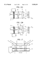
- FIG. 1 is a view illustrating the construction of a conventional optical pickup apparatus.
- a diffraction grating 2 is arranged beside a laser diode 1, which generates a laser beam, for dividing the beam from the laser diode 1 into a main beam and two sub-beams for a tracking servo.
- an objective lens 4 is arranged beside a collimator lens 3 for focusing the parallel light from the collimator lens 3 on an optical disc D.
- a beam splitting prism 5 is arranged between the diffraction grating 2 and the collimator lens 4 for transmitting the incident beam from the diffraction grating 2 at a predetermined ratio and for reflecting the beam reflected in accordance with the information written on the optical disc D.
- a sensor lens 6 is arranged below the beam splitting prism 5 for condensing the beam reflected by the beam splitting prism 5, and an optical detector 7 is arranged for detecting a data signal of the beam passed through the sensor lens 6.
- the beam from the laser diode 1 passes through the diffraction grating 2 and the beam splitting prism 5.
- the beam is then converted into a parallel light by the collimator lens 3 and focused by the objective lens 4. Thereafter, the beam is reflected or diffracted in accordance with the data recorded on the surface of the optical disc D.
- the beam reflected from the surface of the optical disc D passes through the objective lens 4 and the collimator lens 3, and is reflected by the beam splitting prism 5 and detected by the optical detector 7 through the sensor lens 6.
- the conventional optical pickup apparatus when a high density optical disc such as a Digital Video Disk (DVD) is used, the recording density is increased 6-8 times compared to using the optical disc of a conventional CD type. In order to reproduce data recorded on the high density discs, the numerical aperture of the objective lens 4 must be about 0.6. Therefore, the conventional optical pickup apparatus is inadequate to record and reproduce data on and from such discs.
- DVD Digital Video Disk
- the conventional optical pickup apparatus has the following problems which occur when reproducing data recorded on a high density optical disc, such as a DVD having a thickness of 0.6 mm, and an optical disc, such as a CD having a thickness of 1.2 mm.
- FIG. 2 shows in a solid line the beam strength distribution when the beam is focused on the surface of the optical disc D having a thickness of 0.6 mm, using the objective lens 4 with a numerical aperture NA of 0.6.
- the objective lens is designed so that the beam can be focused on the surface of an optical disc D having the thickness of 0.6 mm.
- the beam strength ratio of a main lobe is significantly reduced compared to the DVD having a thickness of 0.6 mm, and the beam strength of a side lobe is relatively increased, so that a crosstalk of the signal recorded on a neighboring track is increased.
- the crosstalk is increased by more than -20 dB.
- the objective lens 4 having a numerical aperture (NA) of 0.6 in order to focus the beam on the surface of the optical disc D having a thickness of 0.6 mm, the spherical aberration with respect to the optical disc is significantly increased compared to the case where the optical disc having a thickness of 1.2 mm is used.
- NA numerical aperture
- LCD liquid crystal shutter
- an optical pickup apparatus which includes a polarization member for converting a polarization of a beam from a laser diode, the beam advancing toward an optical disc, a diffraction member for selectively diffracting the beam passed through the polarization member in accordance with a diffraction state, and an objective lens for focusing the beam from the diffraction member onto the optical disc.
- FIG. 1 is a view illustrating the construction of a conventional optical pickup apparatus
- FIG. 2 is a graph of a beam strength distribution of optical discs having different thicknesses in the conventional art
- FIG. 3 is a perspective view illustrating an optical pickup apparatus according to a first embodiment of the present invention
- FIG. 4 is a view illustrating the construction of an optical pickup apparatus according to the first embodiment of the present invention.
- FIG. 5A is an exploded view illustrating the construction of a liquid crystal shutter (LCS) for the optical pickup apparatus according to the first embodiment of the present invention
- FIG. 5B is an exploded view illustrating the construction of another LCS for an optical pickup apparatus according to the first embodiment of the present invention.
- FIG. 6 is a view illustrating an example of a voltage being applied to an LCS of the optical pickup apparatus according to the first embodiment of the present invention
- FIG. 7A is a view illustrating a change in the polarization direction of a TN liquid crystal in a state where a voltage is not supplied to the liquid crystal of a liquid crystal layer of an optical pickup apparatus according to the first embodiment of the present invention
- FIG. 7B is a view illustrating the polarization direction of a TN liquid crystal where a voltage is supplied to the liquid crystal of a liquid crystal layer of an optical pickup apparatus according to the first embodiment of the present invention
- FIG. 8A is a front view illustrating a circular diffraction hologram for an optical pickup apparatus according to the first embodiment of the present invention
- FIG. 8B is a front view illustrating a square shaped diffraction hologram for an optical pickup apparatus according to the first embodiment of the present invention.
- FIG. 9A is a view illustrating an electrode of an LCS to which a voltage is supplied in the normal white (NW) mode for an optical pickup apparatus according to the first embodiment of the present invention
- FIG. 9B is a front view of the electrode of the LCS of FIG. 9A;
- FIG. 9c is a view illustrating an electrode of an LCS to which a voltage is supplied in the normal black (NB) mode for an optical pickup apparatus according to the first embodiment of the present invention
- FIG. 9D is a front view of the electrode of the LCS of FIG. 9C;
- FIG. 10 is a table illustrating a diffraction efficiency varying based on a grating shape of a diffraction hologram for an optical pickup apparatus according to the first embodiment of the present invention
- FIG. 11 is a graph illustrating a diffraction efficiency of a diffraction state of a diffraction hologram for an optical pickup apparatus according to the first embodiment of the present invention
- FIG. 12A is a view illustrating a state where a voltage is not supplied to a transparent electrode of the LCS to explain the principle of a numerical aperture variation for an object lens of an optical pickup apparatus according to the first embodiment of the present invention
- FIG. 12B is a view illustrating a state where a voltage is supplied to the transparent electrode of the LCS for explaining the principle of a numerical aperture variation for an optical pickup apparatus according to the first embodiment of the present invention
- FIG. 13 is a view illustrating a state where a diffraction beam forwardly advances away from an objective lens due to a diffraction hologram of an optical pickup apparatus according to the first embodiment of the present invention
- FIG. 14A is a view illustrating a state where a diffraction beam laterally advances with respect to an objective lens due to a diffraction hologram wherein a transparent electrode of a liquid crystal plate is circular;
- FIG. 14B is a view illustrating a state where a diffraction beam rearwardly advances from an objective lens due to a diffraction hologram wherein a transparent electrode of a liquid crystal plate is circular;
- FIG. 15A is a view illustrating a state where a diffraction beam laterally advances toward an objective lens due to a diffraction hologram wherein a transparent electrode of a liquid crystal plate is circular or square;
- FIG. 15B is a view illustrating a state where a diffraction beam rearwardly advances from an objective lens due to a diffraction hologram wherein a transparent electrode of a liquid crystal plate is circular or square;
- FIG. 16A is a view illustrating a grating with an index modulation, which may be used in lieu of a diffraction hologram according to the first embodiment of the present invention
- FIG. 16B is a graph showing a relationship between a diffraction efficiency and the position of the grating of FIG. 16A;
- FIG. 17 is a view illustrating a construction of an optical pickup apparatus according to a second embodiment of the present invention.
- FIG. 18 is a view illustrating another example of an optical pickup apparatus of FIG. 17 according to the second embodiment of the present invention.
- FIG. 19 is a view illustrating a construction of an optical pickup apparatus according to a third embodiment of the present invention.
- FIG. 20 is a view illustrating another example of the optical pickup apparatus of FIG. 19 according to the third embodiment of the present invention.
- FIG. 21 is a view illustrating a construction of an optical pickup apparatus according to a fourth embodiment of the present invention.
- FIG. 22A is a view illustrating a diffraction hologram having one circular blocking film for an optical pickup apparatus according to the fourth embodiment of the present invention.
- FIG. 22B is a view illustrating a diffraction hologram having a plurality of circular blocking films for an optical pickup apparatus according to the fourth embodiment of the present invention are formed.
- FIG. 23 is a view illustrating another example of an optical pickup apparatus according to the fourth embodiment of the present invention.
- FIG. 3 is a perspective view illustrating an optical pickup apparatus according to the first embodiment of the present invention
- FIG. 4 is a cut-away view illustrating the optical pickup apparatus of FIG. 3 according to the first embodiment of the present invention.
- a laser diode 11 generates beams with different wavelengths and the beam splitter 12 is arranged beside the laser diode 11 for reflecting a beam having a specific wavelength among the beams from the laser diode 11.
- a collimator lens 13 is arranged beside the beam splitter 12 for converting the beam reflected by the beam splitter 12 into a parallel beam, with the collimator lens 13 being vertical with respect to the laser diode 11.
- a right-angled triangular prism 14 is arranged beside the collimator lens 13 for reflecting the parallel beam from the collimator lens 13 in a predetermined direction.
- a liquid crystal shutter (hereinafter called “a liquid crystal plate”) is arranged above the right-angled triangular prism 14 for converting an S-wave into a P-wave and a P-wave into an S-wave.
- the parallel beam reflected by the right-angled triangular prism 24 includes the S-wave and P-wave.
- a diffraction hologram 16 is arranged above the liquid crystal plate 15 for selectively diffracting the beam from the liquid crystal plate 15 in accordance with the diffraction state of hologram 16.
- An objective lens 17 and an optical disc D are arranged in order above the diffraction hologram 16, so that the beam from the diffraction hologram 16 is focused on the optical disc D by the objective lens 17.
- D 12 denotes a CD type optical disc
- D 6 denotes a DVD type optical disc.
- an optical detector 18 is arranged beside the beam splitter 12 for converting the optical signal corresponding to the beam reflected from the optical disc D into an electrical signal, and for outputting a video or audio signal.
- the beam splitter 12 transmits the beam from the collimator lens 13 onto the optical detector 18 and reflects the beam from the laser diode 11 onto the collimator lens 13.
- FIGS. 5A and 5B show examples of the liquid crystal plate 15, and FIGS. 6-7B are views for explaining the operation of the liquid crystal plate 15 according to the embodiments of the present invention.
- transparent electrodes 23A and 24 are patterned between transparent plates 21 and 22 in accordance with the size and shape of the beam which is to be controlled.
- the beam is output from a polarization plate 26(27).
- the transparent electrode 23A is circular (i.e., ring-shaped), so that a liquid crystal layer 25 is preferably circular.
- the shape of the diffraction hologram 16 may be circular with an interference pattern, as shown in FIG. 8A, or square as shown in FIG. 8B.
- the diffraction hologram 16 is composed of a glass such as BK7 as a medium, LiNbO 3 as a non-linear medium, and a liquid crystal.
- the transparent electrodes 23A, 23B, and 24 formed between the transparent substrates 21 and 22, as shown in FIG. 6, are spaced-apart from each other with the distant "d".
- the transparent electrode 24 is connected to GND and a square pulse is supplied to the circular transparent electrode 23A, causing the liquid crystal molecules in the liquid crystal to orient themselves in a certain direction.
- ⁇ denotes the wavelength
- ⁇ n denotes the difference between two diffraction ratios.
- TN liquid crystal is provided on the liquid crystal layer 25 formed in the region corresponding to the computed distance "d".
- FIG. 7B illustrates that there is no variation in the polarization direction of the TN liquid crystal when a voltage is supplied to the transparent electrode 23A, 23B, and 24 of the liquid crystal plate 15.
- FIG. 7A shows the variation of a polarization direction in a TN liquid crystal layer when a voltage is not supplied to the liquid crystal molecules in the liquid crystal layer.
- the polarization direction of the laser beam incident on the liquid crystal layer 25 is changed by 90 degrees.
- the TN liquid crystal layer 25 includes portions 25a and 25c to which the voltage is supplied.
- the portions 25a and 25c are defined by circularly forming the pattern of the transparent electrode 23A wherein the voltage is supplied to the portion 25a.
- the polarization direction of the liquid crystal layer to which the voltage is supplied remains the same so that the incident beam (S-wave) passes through the liquid crystal layer; however, in the liquid crystal layer to which the voltage is not supplied, the polarization direction is changed by 90°, so that the incident beam (S-wave) is changed to the P-wave and the P-wave is output from that portion of the liquid crystal layer.
- the beam through the liquid crystal is made incident on the diffraction hologram 16 which is a diffraction member. Since the diffraction hologram 16 has a rotation efficiency of 0 (zero) with respect to the S-wave, the S-wave passes through the diffraction hologram 16 as unchanged. Then the beam corresponding to the DVD is transferred to the objective lens 17 and is focused on the disk D. On the other hand, the diffraction hologram 16 diffracts the P-wave, thus blocking the P-wave from advancing toward the disc D.
- FIGS. 9C and 9D show the optical pickup apparatus according to the first embodiment of the present invention during the normal black (NB) mode.
- NB normal black
- the diffraction hologram 16 adapted to the optical pickup apparatus according to the first embodiment of the present invention can control the diffraction efficiency based on the shape and depth of grating and a diffraction state.
- the S-wave is not affected by the diffraction efficiency.
- the P-wave since the diffraction efficiency is high, a large diffraction occurs in the P-wave. Therefore, the P-wave is not made incident on the objective lens 17, thus decreasing the numerical aperture NA of the objective lens 17.
- FIG. 10 is a table containing a diffraction efficiency based on a grating shape of a diffraction hologram for an optical pickup apparatus according to the first embodiment of the present invention.
- the table includes the maximum transmission efficiency ( ⁇ max ) of a 1st order based on the shape of various gratings.
- the optical pickup apparatus is directed to recording and reproducing data from different optical discs, such as discs D 12 and D 6 , each having a different recording density and a different thickness, by properly varying the numerical aperture NA of the objective lens 17, using the liquid crystal plate 15 which polarizes the beam and using the diffraction hologram 16 which changes the diffraction state of the beam.
- the beam converted into the parallel beam by the collimator lens is focused on the surface of the optical disc D by the objective lens 17, for obtaining a desired beam size.
- This beam size is varied in accordance with the size of the beam which is made incident on the objective lens 17.
- the beam which is made incident on the liquid crystal plate 15 is a P-wave
- the P-wave beam passes through the liquid crystal plate 15.
- the polarization direction of the P-wave beam is changed by 90° and the beam is changed to S-wave. Since the diffraction hologram 16 has a diffraction efficiency of 0 (zero) with respect to the S-wave, the diffraction hologram 16 passes the S-wave beam from the plate 15, thus forming a spot on the optical disc D 6 of the DVD using the objective lens 17.
- the beam is selectively focused on the optical disc D 12 for the DVD type or the optical disc D 6 for the CD type.
- the 0-th order beam which is simply reflected from the disc D and the ⁇ 1st order beam which is diffracted from the disc D advance in the reverse direction pass through the beam splitter 12, and are made incident on the optical detector 18 to detect the data signal.
- the beam may be diffracted by the grating portion of the diffraction hologram 16 and may advance far from the objective lens 17.
- it is important to control the beam not to affect the optical detector 18.
- the diffraction angle ( ⁇ d) of the beam which is diffracted by the diffraction hologram 16 is smaller than the total reflection angle ⁇ c (i.e., ⁇ d ⁇ c ), the diffraction beam laterally advances in front of the diffraction hologram 16 as shown in FIG. 12B.
- the S-waves all pass through as shown in FIG. 14A, while the P-wave is diffracted and does not pass therethrough.
- the P-wave is deflected within the diffraction hologram 16 many times and laterally advances in the direction "a".
- FIG. 14B shows rearwardly advancing the beam incident on the diffraction hologram 16.
- the size of the grating is laterally extended by a predetermined width of "d" which is more than the size of the beam passing through the diffraction member and that the condition of ⁇ d> ⁇ c is satisfied, then the S-waves all pass through the hologram 16, while the P-wave is diffracted and rearwardly advanced from the diffraction hologram 16.
- the diffraction beam advances forwardly. In this case, it is impossible to laterally and rearwardly advance the beam with respect to the objective lens 17.
- the optical pickup apparatus is directed to forming a circular transparent electrode 23A of the liquid crystal plate 15, for circularly twisting the liquid crystal molecules of the liquid crystal layer 25 and providing a circular or square diffraction hologram 16.
- a circular or square transparent electrode 23A is provided, for forming a circular or square liquid crystal layer 25 and a circular diffraction hologram 16, whereby it is possible to record and reproduce the data recorded on different optical discs D 12 and D 6 , each disc having a different recording density and a different thickness, by properly varying the numerical aperture NA of the objective lens 17.
- FIG. 15A is a view illustrating a diffraction beam laterally advancing toward an objective lens due to a diffraction hologram wherein a transparent electrode of a liquid crystal plate is circular or square
- FIG. 15B is a view illustrating a diffraction beam rearwardly advancing from an objective lens due to a diffraction hologram wherein a transparent electrode of a liquid crystal plate is circular (e.g., a ring shape) or square.
- the solid line denotes an S-wave
- the hatched portion denotes a P-wave diffracted
- the broken line denotes an S-wave
- FIG. 16A a grating 16A having an index modulation whose diffraction efficiency is varied in the system may be preferably used, instead of the diffraction hologram 16.
- FIG. 16B shows the transmission efficiency of the grating 16A with respect to the location of the grating 16A.
- the construction of the optical pickup apparatus according to the second embodiment of the present invention is similar to the first embodiment of the present invention, except for the absence of a separate diffraction hologram.
- a diffraction hologram 217'a is integrally formed on one side of the objective lens 217', thus simplifying the construction of the system.
- the diffraction hologram 217'a is integrally formed on one side of the objective lens 217' and focuses the beam from a liquid crystal plate 215 to the pit of the optical disc D.
- the optical pickup apparatus is directed to forming a circular transparent electrode of the liquid crystal plate 215 to provide a circular liquid crystal layer. Further, a circular or square diffraction hologram 217'a of the objective lens 217' is formed.
- a circular or square transparent electrode of the liquid crystal plate 225 is formed to provide a circular or square liquid crystal layer, whereby a circular diffraction hologram 227'a of an objective lens 227' may be preferably formed.
- reference numeral 211 denotes a laser diode
- 212 denotes a beam splitter
- 213 denotes a collimator lens
- 214 denotes a right-angled triangular prism
- 218 denotes an optical detector.
- a diffraction hologram 315'a is directly and integrally formed within a liquid crystal plate 315' for simplifying the construction of the system.
- the diffraction hologram 315'a is integrally formed on one side of the liquid crystal plate 315' for converting the S-wave parallel beam reflected by the right-angled triangular prism 314 into the P-wave beam and converting the P-wave beam reflected thereby into the S-wave beam.
- a circular transparent electrode of the liquid crystal plate 315' is formed to provide a circular liquid crystal layer.
- a circular or square diffraction hologram 315'a is formed in the transparent substrate of the liquid crystal plate 315'.
- a circular or square transparent electrode of the liquid crystal plate 325'a may be preferably formed in the transparent substrate of the liquid crystal plate 325'.
- reference numeral 311 denotes a laser diode
- 312 denotes a beam splitter
- 313 denotes a collimator lens
- 318 denotes an optical detector.
- An optical pickup apparatus is directed to forming at least one circular blocking film 416'a, as shown in FIGS. 22A and 22B, in a diffraction hologram 416' for decreasing spherical aberration as shown in FIG. 21.
- At least one circular blocking film 427"a may be preferably formed on a portion of an objective lens 427" for decreasing the spherical aberration.
- the optical pickup apparatus it is possible to record and reproduce data from different optical disc D 12 and D 6 having different recording densities and thicknesses by selectively controlling the size of the beam by blocking certain portions of the beam corresponding to the spherical aberration, based on the circular blocking films 416'a formed on the diffraction holograms 416' and at least one circular blocking film 427"a formed on the objective lens 427.
- reference numeral 411 denotes a laser diode
- 412 denotes a beam splitter
- 413 denotes a collimator lens
- 414 denotes a right-angled triangular prism
- 415 denotes a liquid crystal shutter
- 418 denotes an optical detector.
- the optical pickup apparatus is directed to recording and reading data from at least two different optical discs each having a different recording density and a different thickness, by using one optical pickup apparatus. This is achieved by using a liquid crystal shutter and a diffraction hologram as a numerical aperture control member for controlling the numerical aperture of the objective lens.
Abstract
Description
d=(√(2m).sup.2 -1)λ/2δn (1)
Claims (17)
Applications Claiming Priority (2)
| Application Number | Priority Date | Filing Date | Title |
|---|---|---|---|
| KR1019950067352A KR100206771B1 (en) | 1995-12-29 | 1995-12-29 | Optical pickup device |
| KR67352/1995 | 1995-12-29 |
Publications (1)
| Publication Number | Publication Date |
|---|---|
| US5930219A true US5930219A (en) | 1999-07-27 |
Family
ID=19447675
Family Applications (1)
| Application Number | Title | Priority Date | Filing Date |
|---|---|---|---|
| US08/774,673 Expired - Lifetime US5930219A (en) | 1995-12-29 | 1996-12-26 | Optical pickup device for discs of varying characteristics |
Country Status (5)
| Country | Link |
|---|---|
| US (1) | US5930219A (en) |
| JP (1) | JPH09198702A (en) |
| KR (1) | KR100206771B1 (en) |
| CN (1) | CN1158476A (en) |
| DE (1) | DE19654673A1 (en) |
Cited By (17)
| Publication number | Priority date | Publication date | Assignee | Title |
|---|---|---|---|---|
| EP0915460A1 (en) * | 1997-04-24 | 1999-05-12 | SANYO ELECTRIC Co., Ltd. | Optical pickup |
| US6172957B1 (en) * | 1997-03-27 | 2001-01-09 | Pioneer Electronics Corporation | Optical pickup and multi-layer disc playback apparatus |
| US6181668B1 (en) * | 1996-09-27 | 2001-01-30 | Sanyo Electric Co., Ltd. | Optical pickup device and wavelength selective diffraction grating |
| EP1160779A2 (en) * | 2000-05-31 | 2001-12-05 | Matsushita Electric Industrial Co., Ltd. | Optical pickup and optical information recording/reproducing device |
| US6337841B1 (en) | 1998-10-23 | 2002-01-08 | Samsung Electronics Co., Ltd. | Compatible optical pickup |
| US6385158B1 (en) * | 1997-10-29 | 2002-05-07 | Sanyo Electric Co., Ltd. | Optical pickup device having compatibility with tracking system, and optical disk recording/reproduction apparatus using the same |
| US6449235B1 (en) * | 1998-04-04 | 2002-09-10 | Lg Electronics, Inc. | Optical pick-up apparatus and optical recording/reproducing apparatus using the same |
| US20020141321A1 (en) * | 2001-03-28 | 2002-10-03 | Matsushita Electric Industrial Co., Ltd. | Optical element, optical head, optical recording reproduction device and manufacturing method of optically active polymer film |
| EP1258871A2 (en) * | 2001-05-17 | 2002-11-20 | Konica Corporation | Optical pick-up device and objective lens used therein |
| US6518555B1 (en) * | 1998-03-20 | 2003-02-11 | Pioneer Electronic Corporation | Polarization hologram lens, optical pickup, information reproduction apparatus and information recording apparatus |
| US6552990B1 (en) * | 1996-10-31 | 2003-04-22 | Sanyo Electric Co., Ltd. | Optical head for two different disk thicknesses with a light beam diameter control device |
| US6584057B1 (en) * | 1998-09-18 | 2003-06-24 | Pioneer Corporation | Optical pickup system |
| US20030147330A1 (en) * | 2001-01-25 | 2003-08-07 | Yoshiyuki Teraoka | Light spot shaping device and method,light pickup device, and optical disk apparatus |
| US20040008604A1 (en) * | 1998-11-09 | 2004-01-15 | Youichi Saitoh | Optical information processor and optical element |
| US20040057114A1 (en) * | 2000-12-13 | 2004-03-25 | Leo Hatjasalo | Beam shaper |
| US6804185B2 (en) * | 1999-12-20 | 2004-10-12 | Pioneer Corporation | Optical pickup and information recording and/or reproducing apparatus including the same |
| US20070147735A1 (en) * | 2005-12-22 | 2007-06-28 | Daewoo Electronics Corporation | Optical multiplexer and manufacturing method thereof, optical information recording apparatus and method, and optical information reproducing apparatus and method |
Families Citing this family (7)
| Publication number | Priority date | Publication date | Assignee | Title |
|---|---|---|---|---|
| US6069860A (en) * | 1996-11-20 | 2000-05-30 | Matsushita Electric Industrial Co., Ltd. | Optical head with objective lens having different numerical apertures to minimize light aberration with respect to optical disks of different thicknesses |
| KR100482314B1 (en) * | 1997-01-31 | 2005-07-07 | 엘지전자 주식회사 | Adaptive diffraction gratings and optical pickup devices using them |
| US6437319B1 (en) * | 1997-09-10 | 2002-08-20 | Citizen Watch Co., Ltd. | Optical device |
| KR100280823B1 (en) * | 1997-11-03 | 2001-02-01 | 정선종 | Polarization dependent image generation unit using binary phase holograms |
| TW548643B (en) * | 1998-03-11 | 2003-08-21 | Kenwood Corp | Optical pickup device |
| JP4609301B2 (en) | 2005-12-14 | 2011-01-12 | 船井電機株式会社 | Optical pickup device |
| WO2017191168A1 (en) * | 2016-05-03 | 2017-11-09 | Arges Gmbh | Optical rotation angle measuring system |
Citations (3)
| Publication number | Priority date | Publication date | Assignee | Title |
|---|---|---|---|---|
| US5446565A (en) * | 1993-02-01 | 1995-08-29 | Matsushita Electric Industrial Co., Ltd. | Compound objective lens having two focal points |
| US5495461A (en) * | 1991-08-22 | 1996-02-27 | Matsushita Electric Industrial Co., Ltd. | Optical pickup head apparatus |
| US5638353A (en) * | 1995-05-24 | 1997-06-10 | Nec Corporation | Optical head device |
Family Cites Families (5)
| Publication number | Priority date | Publication date | Assignee | Title |
|---|---|---|---|---|
| AU8706982A (en) * | 1981-09-17 | 1983-05-12 | Miles Laboratories Inc. | Spectrophotometer for analytic and diagnostic purposes |
| JPH05120720A (en) * | 1991-10-28 | 1993-05-18 | Toshiba Corp | Information recording and reproducing device |
| US5281797A (en) * | 1991-12-26 | 1994-01-25 | Hitachi, Ltd. | Short wavelength optical disk head having a changeable aperture |
| JPH0628704A (en) * | 1992-07-10 | 1994-02-04 | Toshiba Corp | Optical head device |
| JP3048768B2 (en) * | 1992-10-08 | 2000-06-05 | 三洋電機株式会社 | Optical head |
-
1995
- 1995-12-29 KR KR1019950067352A patent/KR100206771B1/en not_active IP Right Cessation
-
1996
- 1996-12-26 US US08/774,673 patent/US5930219A/en not_active Expired - Lifetime
- 1996-12-28 DE DE19654673A patent/DE19654673A1/en not_active Withdrawn
- 1996-12-30 CN CN96114090A patent/CN1158476A/en active Pending
-
1997
- 1997-01-06 JP JP9000023A patent/JPH09198702A/en active Pending
Patent Citations (4)
| Publication number | Priority date | Publication date | Assignee | Title |
|---|---|---|---|---|
| US5495461A (en) * | 1991-08-22 | 1996-02-27 | Matsushita Electric Industrial Co., Ltd. | Optical pickup head apparatus |
| US5594713A (en) * | 1991-08-22 | 1997-01-14 | Matsushita Electric Industrial Co., Ltd. | Optical pickup head apparatus |
| US5446565A (en) * | 1993-02-01 | 1995-08-29 | Matsushita Electric Industrial Co., Ltd. | Compound objective lens having two focal points |
| US5638353A (en) * | 1995-05-24 | 1997-06-10 | Nec Corporation | Optical head device |
Cited By (30)
| Publication number | Priority date | Publication date | Assignee | Title |
|---|---|---|---|---|
| US6181668B1 (en) * | 1996-09-27 | 2001-01-30 | Sanyo Electric Co., Ltd. | Optical pickup device and wavelength selective diffraction grating |
| US6552990B1 (en) * | 1996-10-31 | 2003-04-22 | Sanyo Electric Co., Ltd. | Optical head for two different disk thicknesses with a light beam diameter control device |
| US6172957B1 (en) * | 1997-03-27 | 2001-01-09 | Pioneer Electronics Corporation | Optical pickup and multi-layer disc playback apparatus |
| US6160783A (en) * | 1997-04-24 | 2000-12-12 | Sanyo Electric Co., Ltd. | Optical pick-up device |
| EP0915460A1 (en) * | 1997-04-24 | 1999-05-12 | SANYO ELECTRIC Co., Ltd. | Optical pickup |
| EP0915460A4 (en) * | 1997-04-24 | 2005-01-26 | Sanyo Electric Co | Optical pickup |
| US6385158B1 (en) * | 1997-10-29 | 2002-05-07 | Sanyo Electric Co., Ltd. | Optical pickup device having compatibility with tracking system, and optical disk recording/reproduction apparatus using the same |
| US6518555B1 (en) * | 1998-03-20 | 2003-02-11 | Pioneer Electronic Corporation | Polarization hologram lens, optical pickup, information reproduction apparatus and information recording apparatus |
| US20050063280A1 (en) * | 1998-04-04 | 2005-03-24 | Lg Electronics, Inc. | Optical pickup and optical recording/reproducing apparatus using the same |
| US7197002B2 (en) * | 1998-04-04 | 2007-03-27 | Lg Electronics Inc. | Optical pickup and optical recording/reproducing apparatus using the same |
| US6856587B2 (en) | 1998-04-04 | 2005-02-15 | Lg Electronics Inc. | Optical pickup and optical recording/reproducing apparatus using the same |
| US6449235B1 (en) * | 1998-04-04 | 2002-09-10 | Lg Electronics, Inc. | Optical pick-up apparatus and optical recording/reproducing apparatus using the same |
| US6584057B1 (en) * | 1998-09-18 | 2003-06-24 | Pioneer Corporation | Optical pickup system |
| US6337841B1 (en) | 1998-10-23 | 2002-01-08 | Samsung Electronics Co., Ltd. | Compatible optical pickup |
| US20040008604A1 (en) * | 1998-11-09 | 2004-01-15 | Youichi Saitoh | Optical information processor and optical element |
| US6804185B2 (en) * | 1999-12-20 | 2004-10-12 | Pioneer Corporation | Optical pickup and information recording and/or reproducing apparatus including the same |
| US7154837B2 (en) | 2000-05-31 | 2006-12-26 | Matsushita Electric Industrial Co., Ltd. | Optical pickup and optical information recording/reproducing device |
| EP1160779A3 (en) * | 2000-05-31 | 2004-04-21 | Matsushita Electric Industrial Co., Ltd. | Optical pickup and optical information recording/reproducing device |
| EP1160779A2 (en) * | 2000-05-31 | 2001-12-05 | Matsushita Electric Industrial Co., Ltd. | Optical pickup and optical information recording/reproducing device |
| US20040057114A1 (en) * | 2000-12-13 | 2004-03-25 | Leo Hatjasalo | Beam shaper |
| US7307786B2 (en) * | 2000-12-13 | 2007-12-11 | Oy Modines Ltd | Beam shaper |
| US20030147330A1 (en) * | 2001-01-25 | 2003-08-07 | Yoshiyuki Teraoka | Light spot shaping device and method,light pickup device, and optical disk apparatus |
| US7113472B2 (en) * | 2001-03-28 | 2006-09-26 | Matsushita Electric Industrial Co., Ltd. | Optical head including an active polymer film for switching voltage during recording and reproducing processes |
| US20020141321A1 (en) * | 2001-03-28 | 2002-10-03 | Matsushita Electric Industrial Co., Ltd. | Optical element, optical head, optical recording reproduction device and manufacturing method of optically active polymer film |
| US7075880B2 (en) | 2001-05-17 | 2006-07-11 | Konica Corporation | Optical pick-up device and objective lens used therein |
| EP1258871A2 (en) * | 2001-05-17 | 2002-11-20 | Konica Corporation | Optical pick-up device and objective lens used therein |
| EP1258871A3 (en) * | 2001-05-17 | 2006-04-19 | Konica Minolta Opto, Inc. | Optical pick-up device and objective lens used therein |
| US20030165107A1 (en) * | 2001-05-17 | 2003-09-04 | Koji Honda | Optical pick-up device and objective lens used therein |
| US20070147735A1 (en) * | 2005-12-22 | 2007-06-28 | Daewoo Electronics Corporation | Optical multiplexer and manufacturing method thereof, optical information recording apparatus and method, and optical information reproducing apparatus and method |
| US8306376B2 (en) | 2005-12-22 | 2012-11-06 | Wi-Lan Inc. | Method and apparatus for multiplexing optical information for recording and reproducing optical information over optical storage medium |
Also Published As
| Publication number | Publication date |
|---|---|
| DE19654673A1 (en) | 1997-07-03 |
| CN1158476A (en) | 1997-09-03 |
| KR970050349A (en) | 1997-07-29 |
| KR100206771B1 (en) | 1999-07-01 |
| JPH09198702A (en) | 1997-07-31 |
Similar Documents
| Publication | Publication Date | Title |
|---|---|---|
| US5930219A (en) | Optical pickup device for discs of varying characteristics | |
| US5696750A (en) | Optical head apparatus for different types of disks | |
| US5515354A (en) | Optical pickup | |
| US6819647B2 (en) | Optical information processor and optical element | |
| JPH09180240A (en) | Optical head | |
| JPH0254434A (en) | Optical head | |
| CA1328134C (en) | Method for detecting tracking error in optical disk system and its optical system devices therefor | |
| KR0176898B1 (en) | Optic-pick-up device using cd/dvd | |
| KR19990049998A (en) | Light Control LCD Dual Focus Optical Pickup Device | |
| JP2724095B2 (en) | Optical pickup | |
| KR19990050011A (en) | Dual focus optical pickup device using liquid crystal device | |
| KR19990050013A (en) | Dual Focus Optical Pickup Device Using Reflective Liquid Crystal Element | |
| KR19990050014A (en) | Reflective Dual Focus Optical Pickup Device | |
| KR19990050001A (en) | Dual Focus Optical Pickup Device Using Light Transmissive Reflection | |
| KR19990049993A (en) | Dual Focus Optical Pickup Device using Light Control | |
| KR19990050017A (en) | Reflective Dual Focus Optical Pickup Device | |
| KR19990050020A (en) | LCD Hologram Dual Focus Optical Pickup Device | |
| KR19990049997A (en) | Reflective Dual Focus Optical Pickup Device | |
| KR19990049999A (en) | Dual Focus Optical Pickup Device Using Optical Control Liquid Crystal Panel | |
| KR19990049994A (en) | Dual focus optical pickup device using liquid crystal device | |
| KR19990049995A (en) | Dual focus optical pickup device using optical control liquid crystal device | |
| KR19990050016A (en) | Reflective Dual Focus Optical Pickup Device | |
| KR19990050009A (en) | Dual Focus Optical Pickup Device Using Aperture Control | |
| KR19990050012A (en) | Dual focus optical pickup device using liquid crystal device | |
| KR19990050021A (en) | Dual Focus Optical Pickup Device Using Optical Control Liquid Crystal Panel |
Legal Events
| Date | Code | Title | Description |
|---|---|---|---|
| AS | Assignment |
Owner name: LG ELECTRONICS INC., KOREA, REPUBLIC OF Free format text: ASSIGNMENT OF ASSIGNORS INTEREST;ASSIGNOR:KIM, YOUNG SIK;REEL/FRAME:008381/0995 Effective date: 19961213 |
|
| FEPP | Fee payment procedure |
Free format text: PAYOR NUMBER ASSIGNED (ORIGINAL EVENT CODE: ASPN); ENTITY STATUS OF PATENT OWNER: LARGE ENTITY |
|
| FPAY | Fee payment |
Year of fee payment: 4 |
|
| REMI | Maintenance fee reminder mailed | ||
| FEPP | Fee payment procedure |
Free format text: PETITION RELATED TO MAINTENANCE FEES GRANTED (ORIGINAL EVENT CODE: PMFG); ENTITY STATUS OF PATENT OWNER: LARGE ENTITY Free format text: PETITION RELATED TO MAINTENANCE FEES FILED (ORIGINAL EVENT CODE: PMFP); ENTITY STATUS OF PATENT OWNER: LARGE ENTITY |
|
| REMI | Maintenance fee reminder mailed | ||
| REIN | Reinstatement after maintenance fee payment confirmed | ||
| FP | Lapsed due to failure to pay maintenance fee |
Effective date: 20070727 |
|
| PRDP | Patent reinstated due to the acceptance of a late maintenance fee |
Effective date: 20071226 |
|
| FPAY | Fee payment |
Year of fee payment: 8 |
|
| STCF | Information on status: patent grant |
Free format text: PATENTED CASE |
|
| SULP | Surcharge for late payment | ||
| FEPP | Fee payment procedure |
Free format text: PAYER NUMBER DE-ASSIGNED (ORIGINAL EVENT CODE: RMPN); ENTITY STATUS OF PATENT OWNER: LARGE ENTITY Free format text: PAYOR NUMBER ASSIGNED (ORIGINAL EVENT CODE: ASPN); ENTITY STATUS OF PATENT OWNER: LARGE ENTITY |
|
| AS | Assignment |
Owner name: IONOSEP X HOLDINGS L.L.C., DELAWARE Free format text: ASSIGNMENT OF ASSIGNORS INTEREST;ASSIGNOR:LG ELECTRONICS INC.;REEL/FRAME:022510/0555 Effective date: 20090218 |
|
| AS | Assignment |
Owner name: LG ELECTRONICS INC., KOREA, DEMOCRATIC PEOPLE'S RE Free format text: CONFIRMATORY ASSIGNMENT;ASSIGNOR:LG CORP.;REEL/FRAME:022645/0497 Effective date: 20090227 |
|
| AS | Assignment |
Owner name: IONOSEP X HOLDINGS L.L.C., DELAWARE Free format text: ASSIGNMENT OF ASSIGNORS INTEREST;ASSIGNOR:LG ELECTRONICS INC.;REEL/FRAME:022659/0383 Effective date: 20090218 |
|
| FPAY | Fee payment |
Year of fee payment: 12 |