US5931254A - Non-contact operator presence sensor - Google Patents
Non-contact operator presence sensor Download PDFInfo
- Publication number
- US5931254A US5931254A US08/846,281 US84628197A US5931254A US 5931254 A US5931254 A US 5931254A US 84628197 A US84628197 A US 84628197A US 5931254 A US5931254 A US 5931254A
- Authority
- US
- United States
- Prior art keywords
- operator
- controller
- power
- output signal
- sensor
- Prior art date
- Legal status (The legal status is an assumption and is not a legal conclusion. Google has not performed a legal analysis and makes no representation as to the accuracy of the status listed.)
- Expired - Fee Related
Links
- 230000007246 mechanism Effects 0.000 claims description 33
- 230000005855 radiation Effects 0.000 claims description 9
- 230000003287 optical effect Effects 0.000 description 24
- 238000001514 detection method Methods 0.000 description 5
- 230000005355 Hall effect Effects 0.000 description 2
- 230000000712 assembly Effects 0.000 description 2
- 238000000429 assembly Methods 0.000 description 2
- 238000010586 diagram Methods 0.000 description 2
- 210000003414 extremity Anatomy 0.000 description 2
- 239000012530 fluid Substances 0.000 description 2
- 210000001624 hip Anatomy 0.000 description 2
- 238000000034 method Methods 0.000 description 2
- 239000003086 colorant Substances 0.000 description 1
- 238000004891 communication Methods 0.000 description 1
- 238000010348 incorporation Methods 0.000 description 1
- 239000012528 membrane Substances 0.000 description 1
Images


Classifications
-
- E—FIXED CONSTRUCTIONS
- E02—HYDRAULIC ENGINEERING; FOUNDATIONS; SOIL SHIFTING
- E02F—DREDGING; SOIL-SHIFTING
- E02F9/00—Component parts of dredgers or soil-shifting machines, not restricted to one of the kinds covered by groups E02F3/00 - E02F7/00
- E02F9/16—Cabins, platforms, or the like, for drivers
-
- E—FIXED CONSTRUCTIONS
- E02—HYDRAULIC ENGINEERING; FOUNDATIONS; SOIL SHIFTING
- E02F—DREDGING; SOIL-SHIFTING
- E02F9/00—Component parts of dredgers or soil-shifting machines, not restricted to one of the kinds covered by groups E02F3/00 - E02F7/00
- E02F9/26—Indicating devices
-
- E—FIXED CONSTRUCTIONS
- E02—HYDRAULIC ENGINEERING; FOUNDATIONS; SOIL SHIFTING
- E02F—DREDGING; SOIL-SHIFTING
- E02F9/00—Component parts of dredgers or soil-shifting machines, not restricted to one of the kinds covered by groups E02F3/00 - E02F7/00
- E02F9/24—Safety devices, e.g. for preventing overload
-
- E—FIXED CONSTRUCTIONS
- E02—HYDRAULIC ENGINEERING; FOUNDATIONS; SOIL SHIFTING
- E02F—DREDGING; SOIL-SHIFTING
- E02F3/00—Dredgers; Soil-shifting machines
- E02F3/04—Dredgers; Soil-shifting machines mechanically-driven
- E02F3/28—Dredgers; Soil-shifting machines mechanically-driven with digging tools mounted on a dipper- or bucket-arm, i.e. there is either one arm or a pair of arms, e.g. dippers, buckets
- E02F3/34—Dredgers; Soil-shifting machines mechanically-driven with digging tools mounted on a dipper- or bucket-arm, i.e. there is either one arm or a pair of arms, e.g. dippers, buckets with bucket-arms, i.e. a pair of arms, e.g. manufacturing processes, form, geometry, material of bucket-arms directly pivoted on the frames of tractors or self-propelled machines
- E02F3/3414—Dredgers; Soil-shifting machines mechanically-driven with digging tools mounted on a dipper- or bucket-arm, i.e. there is either one arm or a pair of arms, e.g. dippers, buckets with bucket-arms, i.e. a pair of arms, e.g. manufacturing processes, form, geometry, material of bucket-arms directly pivoted on the frames of tractors or self-propelled machines the arms being pivoted at the rear of the vehicle chassis, e.g. skid steer loader
Definitions
- the present invention relates to power machinery. More particularly, the present invention relates to an operator presence sensor for power machinery.
- Power machines such as skid steer loaders, typically have a frame which supports a cab and a movable lift arm which, in turn, supports a work tool such as a bucket.
- the movable lift arm is pivotally coupled to the frame of the skid steer loader by power actuators which are commonly hydraulic cylinders.
- the tool is coupled to the lift arm by one or more additional power actuators which are also commonly hydraulic cylinders.
- An operator manipulating the skid steer loader raises and lowers the lift arm, and manipulates the tool, by actuating the hydraulic cylinders coupled to the lift arm and a hydraulic cylinder coupled to the tool.
- the lift arm moves generally vertically upward.
- the lift arm moves generally vertically downward.
- the operator can manipulate the tool (e.g., tilt the bucket) by controlling the hydraulic cylinder coupled to the lift arm and the working tool to increase or decrease in length, as desired.
- Skid steer loaders also commonly have an engine which drives the hydraulic pump to, in turn, power hydraulic traction motors which power movement of the skid steer loader.
- the traction motors are commonly coupled to the wheels through a drive mechanism such as a chain drive.
- the lift arm and the tool, or the drive mechanism, or both be rendered inoperable.
- the hydraulic cylinders used to raise and lower the lift arm are locked out of operation.
- an operator presence switch is coupled to the hydraulic circuit controlling the hydraulic cylinders to render the hydraulic lift cylinders inoperable when the operator presence switch indicates that the operator is out of proper operating position.
- One example of such a system is set out in the Minor et al. U.S. Pat. No. 4,389,154.
- moveable operator restraint bars are provided. When the operator restraint bars are moved to a retracted or an inoperative position, mechanical brakes or wheel locks lock the wheels of the skid steer loader.
- mechanical brakes or wheel locks lock the wheels of the skid steer loader.
- miniexcavators typically have a base portion which is supported by a pair of track assemblies.
- the track assemblies are powered by hydraulic motors.
- the base portion typically supports a house, or operator support portion.
- the house is rotatable relative to the base portion. Rotation is powered by a hydraulic slew motor.
- Miniexcavators also typically have a number of other features.
- a boom is typically coupled to the house.
- a power actuator such as a hydraulic cylinder, is coupled to the boom to pivot the boom relative to the house about an arc substantially located in a vertical plane.
- the boom is also typically pivotable substantially in a horizontal plane. This type of pivoting movement is accomplished through the use of a hydraulic cylinder (referred to as an offset cylinder) coupled to the house and to the boom.
- a hydraulic cylinder referred to as an offset cylinder
- An arm is coupled to the distal end of the boom, and is also typically pivotable relative to the boom through use of a hydraulic cylinder.
- a tool is commonly coupled to the end of the arm and is manipulated, also through the use of a hydraulic cylinder. Such a tool may typically be a bucket pivotally coupled to the arm.
- vehicle seat switches have been used in the past in order to determine the presence of an operator in the power machine.
- Such seat switches typically involve a spring, or some type of bias member which biases the seat of the power machine in an upward direction.
- a seat switch is generally located beneath the seat and is actuated when a load is applied to the seat and deactuated when the load is removed from the seat.
- the switch is typically coupled to an electrical circuit which provides a signal indicative of whether the load is applied to the seat.
- some conventional seat switch mechanisms are configured to operate with seats which pivot in a fore and aft direction, or seats which move in a substantially vertical direction under an operator load.
- a power machine includes a frame and a plurality of power actuators operably coupled to the frame.
- a power circuit is coupled to the power actuators and provides power to the power actuators.
- a cab is operably coupled to the frame and defines an operator compartment.
- the cab includes a seat supported in the operator compartment.
- a non-contact operator presence sensor is coupled proximate the cab and is configured to sense presence of an occupant in a predefined volume proximate the seat.
- the operator presence sensor provides a sensor output signal indicative of operator presence.
- a controller is coupled to the operator presence sensor and is configured to control operation of at least one of the plurality of power actuators based on the sensor output signal.
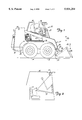
- FIG. 1 is a side elevational view of a skid steer loader of the present invention.
- FIG. 2 is a side view of a portion of an operator compartment of the skid steer loader shown in FIG. 1.
- FIG. 3 illustrates operation of an operator presence sensing system in accordance with the present invention.
- FIG. 4 is a block diagram of one embodiment of a control system in accordance with the present invention.
- FIG. 1 is a side elevational view of a skid steer loader 10 of the present invention.
- Skid steer loader 10 includes a frame 12 supported by wheels 14.
- Frame 12 also supports a cab 16 which defines an operator compartment and which substantially encloses a seat 19 on which an operator sits to control skid steer loader 10.
- a seat bar 21 is pivotally coupled within cab 16. When the operator occupies seat 19, the operator then pivots seat bar 21 from the raised position (shown in phantom in FIG. 1) to the lowered position shown in FIG. 1.
- the operator compartment defined by cab 16 also includes a pair of hand grips 23 and 25 which are attached to steering levers, and which preferably support a number of operator actuable input devices (such as switches, buttons, etc.).
- the steering levers and the operator actuable input devices are used by the operator to control the operation of skid steer loader 10.
- the operator compartment may, in one preferred embodiment, also include foot pedals or other operator actuable input devices which are actuated by the operator's feet, and which are also used to control the operation of skid steer loader 10.
- the operator compartment defined by cab 16 further includes non-contact operator presence sensor 27.
- sensor 27 is an infrared sensor which includes optical elements that focus the area of detection on a volume which is closely proximate seat 19. Therefore, sensor 27 detects the presence of an object in the sensed volume. Sensor 27 is described in greater detail later in the specification.
- a lift arm 17 is coupled to frame 12 at pivot points 20 (only one of which is shown in FIG. 1, the other being identically disposed on the opposite side of loader 10).
- a pair of hydraulic cylinders 22 (one of which is shown in FIG. 1) are pivotally coupled to frame 12 at pivot points 24 and to lift 17 at pivot points 26.
- Lift arm 17 is also coupled to a working tool which, in the preferred embodiment, is a bucket 28.
- Lift arm 17 is pivotally coupled to bucket 28 at pivot points 30.
- another hydraulic cylinder 32 is pivotally coupled to lift arm 17 at pivot point 34 and to bucket 28 at pivot point 36. While only one cylinder 32 is shown, it is to be understood that any desired number of cylinders (or other power actuators) can be used to work bucket 28 or any other suitable tool or attachment.
- the operator residing in cab 16 can manipulate lift arm 17 or bucket 28 by selectively actuating hydraulic cylinders 22 and 32.
- lift arm 17 and consequently bucket 28
- lift arm 17 move generally vertically upward and downward, respectively, in the direction generally indicated by arrow 38.
- bucket 28 pivots generally along an arc indicated by arrow 40.
- FIG. 2 is a side view of a portion of the operator compartment defined by cab 16.
- FIG. 2 illustrates that operator presence sensor 27 is configured to detect the presence of an object in a sensed volume indicated by the dashed line 42 shown in FIG. 2.
- sensed volume 42 is preferably three dimensional and extends transversely across a portion of seat 19.
- sensed volume 42 is located proximate a volume which would be normally occupied by the hip region of an operator. This reduces the likelihood that the limbs, or upper torso of the operator, when moving during operation of loader 10, will move out of the sensed volume and thereby cause an erroneous vacancy detection (or operator absent detection) by the operator presence sensor 27.
- FIG. 2 shows presence sensor 27 located in a forward region of the operator compartment defined by cab 16.
- sensor 27 is located in an upward, forward corner of the operator compartment.
- sensor 27 there are many different suitable locations for sensor 27, including substantially any area where operator presence sensor 27 can sense a desired volume proximate seat 19.
- FIG. 3 illustrates the operation of operator presence sensor 27 in greater detail.
- operator presence sensor 27 includes light emitter 44, a plurality of light detectors (in the preferred embodiment shown in FIG. 3 there are three light detectors) 46, 48 and 50, an optics portion 52 associated with light emitter 44 and an optics portion 54 associated with detectors 46, 48 and 50.
- Light emitter 44 is preferably a light emitting diode which emits light in a desired frequency range, such as in the infrared range.
- Light detectors 46, 48 and 50 are preferably detectors which detect light in the range emitted by light emitter 44. It should be noted that any suitable number or type of detectors can be used (as described in greater detail later). However, in the preferred embodiment shown in FIG. 3, three detectors are used.
- Optics portion 52 preferably includes a dispersive element and collimating element which substantially uniformly disperses the light emitted by emitter 44 and columniates that light and directs it in a direction such that it impinges on the desired sensed volume 42.
- the radiation emanating from lens 52 preferably impinges on, and illuminates a substantial part, or all, of sensed volume 42.
- the light emanating from lens 52 is shown as a cylinder or parallelapiped 56 which covers a substantial portion of sensed volume 42. It should be noted, however, that the light emanating from lens 52 can be any suitable shape, such as a cone, or another suitable shape.
- Optical portion 54 includes one or more lenses what serve to focus light emitted by emitter 44 and reflected from a point or an object residing in sensed volume 42 back to detectors 46, 48, and 50.
- the lenses in optical portion 54 focus light reflected from a point or an object residing in a volume 58 back to detector 46.
- the lenses in optical portion 54 focus light reflected from a point or an object in volume 60 back to detector 48, and they focus light reflected from an object in volume 62 back to detector 50.
- the volumes 58, 60 and 62 are generally cone shaped. However, it should be noted that any suitable shape can be used, and this can be obtained by simply changing the configuration of the lenses forming optical portion 54.
- FIG. 3 also illustrates that, in the preferred embodiment, the volumes 58, 60 and 62, from which light is reflected and sensed by detectors 46, 48 and 50, overlap in the sensed volume 42. This feature is used in processing the sensor signals received from detectors 46, 48 and 50, as is described with respect to FIG. 4.
- FIG. 4 illustrates a block diagram of control circuit 64.
- Control circuit 64 includes optical sensors or detectors 46, 48 and 50, seat bar sensor 66, power supply 68, ignition switch 70, traction lock override switch 72, traction switch 74, controller assembly 76, traction lockout mechanism 78, hydraulic lockout mechanism 80, drive mechanism 82, hydraulic circuit 84, and power actuators, such as cylinders 22 and 32.
- Controller assembly 76 includes controller 86 and display 88.
- controller 86 is a digital computer, or other suitable microcontroller, along with associated circuitry such as memory, timing circuitry, and other suitable support circuitry.
- Display 88 is preferably any suitable operator-observable display such as LEDs, an LCD display, a CRT display or any other suitable display.
- Controller 86 receives inputs from optical sensors 46, 48 and 50, seat bar sensor 66, traction lock override switch 72 and traction switch 74.
- Ignition switch 70 is coupled to power supply 68. Upon closing of ignition switch 70, power is supplied from power supply 68 to the remainder of the system.
- controller 86 Based on the inputs received, controller 86 provides two outputs to traction lockout mechanism 78, and an output to hydraulic lockout mechanism 80. Controller 86 also provides an output to display 88 which provides operator-observable indicia indicating the state of various operating conditions of machine 10.
- traction lockout mechanism 78 and hydraulic lockout mechanism 80 provide outputs to drive mechanism 82 and hydraulic circuit 84, respectively.
- Hydraulic circuit 84 provides an output (in the embodiment shown in FIG. 4) to lift and tilt cylinders 22, 32.
- optical sensors 46, 48 and 50 provide signals to controller 86 indicating whether anything is residing in volumes 58, 60 and 62, respectively. Based on these signals, controller 86 determines whether an operator present condition exists, or whether an operator absent condition exists. This is described in greater detail below.
- Seat bar sensor 66 is preferably a Hall effect position sensor more fully described in U.S. Pat. No. 5,542,493, which is incorporated fully herein by reference.
- Seat bar sensor 66 senses whether seat bar 21 is in the raised or lowered position (shown in FIG. 2). In the preferred embodiment, seat bar sensor 66 is activated when the operator pulls seat bar 21 into the lowered position shown in FIG. 2.
- seat bar sensor 66 provides a signal to controller 86 which is active when seat bar 21 is in the lowered position and inactive when seat bar 21 is in the raised position, or in any position other than the lowered position.
- Ignition switch 70 is preferably a typical key-type ignition switch used in supplying power from power supply 68 to the basic electrical system in loader 10. Upon the closure of ignition switch 70, power is also supplied to controller 86 which senses that switch 70 is closed. Of course, it should be noted that switch 70 could also be another type of operator actuable input, such as a rocker switch, a membrane keypad input, or another suitable input.
- Traction lock switch 74 is preferably an operator-controlled pedal actuated switch accessible from the operator compartment defined by cab 16.
- the pedal is preferably configured as an over-center device.
- traction switch 74 provides an input to controller 86 requesting controller 86 to activate traction lockout mechanism 78.
- Traction lock override switch 72 is preferably a manually operated switch which is also located in the operator compartment defined by cab 16.
- Switch 72 can be of any suitable configuration, but is preferably a push button switch located on a dash panel in a forward region of the operator compartment and is used to override certain selected lockout conditions.
- Traction lockout mechanism 78 in the preferred embodiment, comprises the mechanism more fully described in co-pending U.S. patent application Ser. No. 08/198,957, filed on Feb. 22, 1994. Briefly, traction lockout mechanism 78 locks or unlocks drive mechanism 82 in response to input signals to either preclude movement of skid steer loader 10 or allow movement of skid steer loader 10, respectively.
- Hydraulic lockout mechanism 80 is more fully described in co-pending U.S. patent application Ser. No. 08/199,120, filed Feb. 22, 1994.
- hydraulic circuit 68 includes hydraulic valves which are actuated to provide fluid under pressure to power actuators on loader 10, such as cylinders 22 and 32, to achieve desired manipulation of those actuators.
- Hydraulic lockout mechanism 80 in the preferred embodiment, includes any number of lock valves interposed between the valves in hydraulic circuit 84 and the power actuators. Upon receiving appropriate control signals from controller 86, the lock valves in hydraulic lockout mechanism 80 preclude hydraulic circuit 84 from providing fluid under pressure to the power actuators, thereby locking the power actuators, or allowing only selected operations of the power actuators.
- hydraulic lockout mechanism 80 could also include any other suitable mechanism for limiting or precluding operation of selected power actuators.
- circuit 64 During normal operation of circuit 64, an operator enters the operator compartment defined by cab 16 and occupies seat 19. The operator then lowers seat bar 21 into the lowered position shown in FIG. 1. The operator then closes ignition switch 70 supplying power to the basic electrical system, to controller assembly 76, and to the remainder of the control system. Optical sensors 46, 48 and 50, and seat bar sensor 66, provide signals to controller 86 indicating that seat 19 is occupied and that seat bar 21 is in the lowered position.
- controller 86 Upon receiving such signals, controller 86 provides appropriate signals to traction lockout mechanism 78 to unlock drive mechanism 82, and allow movement of loader 10, and to hydraulic lockout mechanism 80 to unlock hydraulic circuit 84 and allow manipulation of the power actuators on loader 10. Also, controller 86 provides display signals to display 88 which indicate that seat 19 is occupied, seat bar 21 is in the lowered position, and hydraulic lockout mechanism 80 has been sent a signal by controller 86 to unlock hydraulic circuit 84 and drive mechanism 82 and that controller 86 does not detect any system problems.
- controller 86 If controller 86 has not received a signal from optical sensors 46, 48 and 50 indicating that seat 19 is occupied, and has not received a signal from seat bar sensor 66 indicating that seat bar 21 is in the lowered position, controller 86 provides appropriate signals to traction lockout mechanism 78 and hydraulic lockout mechanism 80 locking drive mechanism 82 and hydraulic circuit 84, respectively.
- Controller 86 can be programmed to determine that the operator is present in seat 19 when any one, or any combination of, sensors 46, 48 and 50 provide a signal indicating the presence of an object in the corresponding volumes 58, 60 and 62. However, in the preferred embodiment, controller 86 does not interpret the signals from optical sensors 46, 48 and 50 as though they are indicating an operator present condition unless all three sensors provide a signal which indicates that something is present in the associated volumes 58, 60 and 62, respectively. In other words, all three sensors preferably must sense the presence of an object in order for controller 86 to determine that an operator is present in seat 19.
- volume 58, 60 and 62 can be positioned such that they overlap in the sensed volume 42.
- controller 86 can be substantially assured that the item being detected by optical sensors 46, 48 and 50 is actually within the sensed volume 42, and is not outside that volume.
- seat bar 21 when raised and lowered, can pass through, or reside in, any of volumes 58, 60 and 62.
- controller 86 will not mistakenly determine that an operator is present based on the signals received from optical sensors 46, 48 and 50 due to seat bar 21. Rather, controller 86 will only determine that an operator is present when something resides in sensed volume 42, which preferably coincides to the hip region of an operator properly seated within seat 19.
- sensors 46, 48 and 50 have been described as sensors which simply provide an on/off type signal indicative of the presence or absence of an object in the sensed volume, they could be other types of sensors as well.
- the sensors can provide an analog output which has a magnitude indicative of the presence of an object or some other characteristic of the object as well, such as size.
- controller 86 may preferably perform other analysis on the signals received from sensors 46, 48 and 50 as well. For example, in one preferred embodiment, controller 86 compares signals received from closely proximate time intervals. In this way, controller 86 determines whether movement has occurred in the region of seat 19. For instance, if optical sensors 46, 48 and 50 are progressively activated and deactivated, that would tend to indicate to controller 86 that an object has moved through volumes 58, 60 and 62, one at a time. This could arise, for instance, by the operator waving a limb or a tool proximate, detector 27. Further, this could possibly result from the movement of seat bar 21.
- optical sensors 46, 48 and 50 can be replaced by a charge coupled image sensing device, or other suitable cameras with overlapping fields of view, the overlapping fields of view corresponding to volumes 58, 60 and 62.
- the signals received by controller 86 are analyzed in one of a number of ways. For instance, such signals are preferably analyzed by controller 86 to perform a shape analysis. In essence, a shape analysis determines whether an object which is larger or smaller than expected (or which has a silhouette which is different than expected) is within the sensed volume 42. In performing such an analysis, controller 86 essentially counts a number of picture elements (pixels) in any given image sensed by the charge coupled devices. Controller 86 then compares the size of that image to the size of an expected image to determine whether an appropriate image has been intruded into volume 42.
- pixels picture elements
- controller 86 performs a color content analysis.
- the color of an object sensed by the charge coupled devices is determined by analyzing relative intensities of the red, green and blue colors recorded. This is preferably done by a hue, intensity, saturation (HIS) analysis technique which is a known technique.
- HIS hue, intensity, saturation
- controller 86 may, in another preferred embodiment, perform object motion analysis. This is done in a similar fashion to the embodiment where optical sensors 46, 48 and 50 are simply radiation detectors. In other words, controller 86 compares the image signals received from the optical sensors during two different time periods to determine whether an sensed object has moved within the fields of view of the charge coupled image sensors.
- detector 27 does not only include three optical sensors, but is implemented using an integrated circuit device which has many more optical sensors, such as an array of 256 optical sensors.
- the optical sensors are not charge coupled image sensors, they still provide a great deal more information than simply three overlapping radiation detectors.
- controller 86 preferably does a fairly detailed analysis of the silhouette of the item sensed by the detectors. This is then used to discriminate between different items which may intrude into the fields of detection of the sensors. For example, this information can be used to distinguish between an operator in seat 19, and a tool which has been set on seat 19, or seat bar 21, or any other item, other than an operator, which has a different silhouette than an operator.
- sensors 46, 48 and 50 can be provided with a separate controller (not shown) which performs the necessary analysis on the signals received from the sensors.
- the controller then preferably communicates with controller 86 using a serial communication stream.
- the present invention provides a non-contact operator presence sensor on power machines, such as skid steer loaders and miniexcavators.
- the particular implementation of the sensor can take one of a number of different embodiments and the output signals from the sensor can be analyzed in many different ways to obtain desired information.
Abstract
Description
Claims (19)
Priority Applications (6)
| Application Number | Priority Date | Filing Date | Title |
|---|---|---|---|
| US08/846,281 US5931254A (en) | 1997-04-30 | 1997-04-30 | Non-contact operator presence sensor |
| CA002234009A CA2234009C (en) | 1997-04-30 | 1998-04-06 | Non-contact operator presence sensor |
| AU60717/98A AU738671B2 (en) | 1997-04-30 | 1998-04-08 | Non-contact operator presence sensor |
| EP98106936A EP0875633A3 (en) | 1997-04-30 | 1998-04-16 | Non-contact operator presence sensor |
| KR1019980014670A KR19980081697A (en) | 1997-04-30 | 1998-04-24 | Non-contact driver seating sensor |
| BR9801475-7A BR9801475A (en) | 1997-04-30 | 1998-04-28 | Guiding platform loader and motorized machine |
Applications Claiming Priority (1)
| Application Number | Priority Date | Filing Date | Title |
|---|---|---|---|
| US08/846,281 US5931254A (en) | 1997-04-30 | 1997-04-30 | Non-contact operator presence sensor |
Publications (1)
| Publication Number | Publication Date |
|---|---|
| US5931254A true US5931254A (en) | 1999-08-03 |
Family
ID=25297435
Family Applications (1)
| Application Number | Title | Priority Date | Filing Date |
|---|---|---|---|
| US08/846,281 Expired - Fee Related US5931254A (en) | 1997-04-30 | 1997-04-30 | Non-contact operator presence sensor |
Country Status (6)
| Country | Link |
|---|---|
| US (1) | US5931254A (en) |
| EP (1) | EP0875633A3 (en) |
| KR (1) | KR19980081697A (en) |
| AU (1) | AU738671B2 (en) |
| BR (1) | BR9801475A (en) |
| CA (1) | CA2234009C (en) |
Cited By (41)
| Publication number | Priority date | Publication date | Assignee | Title |
|---|---|---|---|---|
| US6030169A (en) * | 1998-08-07 | 2000-02-29 | Clark Equipment Company | Remote attachment control device for power machine |
| US6189646B1 (en) * | 1998-11-30 | 2001-02-20 | Clark Equipment Company | Traction lock/momentary override |
| US20020135238A1 (en) * | 2001-03-22 | 2002-09-26 | Stephen Cole | Finger operated control panel |
| US6457545B1 (en) | 2000-06-05 | 2002-10-01 | Delta Systems, Inc. | Hall effect seat switch |
| US6536552B2 (en) * | 2000-06-06 | 2003-03-25 | Linde Aktiengesellschaft | Industrial truck with safety device |
| US6577909B1 (en) * | 1999-03-31 | 2003-06-10 | Caterpillar Inc. | Method for automatically shutting down a machine during an operator's absence |
| US20030155167A1 (en) * | 1999-06-04 | 2003-08-21 | Kamen Dean L. | Personal transporter |
| US20040055558A1 (en) * | 2002-09-25 | 2004-03-25 | Mcelroy Jay | System and method for vehicle idle reduction |
| US20040099461A1 (en) * | 2002-11-27 | 2004-05-27 | Miiller Kevin J. | Lateral operator restraint system and position sensor for material handler |
| US20040136821A1 (en) * | 2003-01-14 | 2004-07-15 | New Holland North America, Inc. | Skid steer loader boom and bucket controls |
| US20040262978A1 (en) * | 2003-06-26 | 2004-12-30 | Young Oliver J. | Vehicle occupant sensing system having sensor assemblies with variable biasing member |
| US20040263344A1 (en) * | 2003-06-26 | 2004-12-30 | Oliver Young | Vehicle occupant sensing system having a low profile sensor assembly |
| US20040262963A1 (en) * | 2003-06-26 | 2004-12-30 | Asad Ali | Vehicle seat assembly having a vehicle occupant sensing system and a seat cushion insert positioned therein |
| US20040262962A1 (en) * | 2003-06-26 | 2004-12-30 | Young Oliver J. | Vehicle occupant sensing system having discrete wiring |
| US20050029843A1 (en) * | 2003-06-26 | 2005-02-10 | Young Oliver J. | Vehicle occupant sensing system having an upper slide member with an emitter interference member |
| US20050068185A1 (en) * | 2003-09-29 | 2005-03-31 | Nattel Group, Inc. | System and method for monitoring the operational condition of a motor vehicle |
| US20050093350A1 (en) * | 2003-06-26 | 2005-05-05 | Ali Asad S. | Vehicle seat assembly having a vehicle occupant sensing system and a seat cushion insert |
| US6901322B1 (en) | 2003-12-30 | 2005-05-31 | Lear Corporation | Method of predicting an empty seat condition in an occupancy sensing system |
| US20050138784A1 (en) * | 2003-12-30 | 2005-06-30 | Nathan John F. | Method of testing a sensor array incorporated into a vehicle seat |
| US20050140358A1 (en) * | 2003-12-30 | 2005-06-30 | Kennedy Karl R. | Method of determining an equivalent value for a failed sensor in a vehicle seat having an occupancy sensing system |
| US20050149284A1 (en) * | 2003-12-30 | 2005-07-07 | Nathan John F. | Method of tuning a sensor array for occupancy sensing in a vehicle seat |
| US20050149461A1 (en) * | 2003-12-30 | 2005-07-07 | Karl Kennedy | Method of occupancy classification in a vehicle seat |
| US20050151355A1 (en) * | 2004-01-14 | 2005-07-14 | Samuel Hanlon | Vehicle seat assembly having a field effect sensor for detecting seat position |
| US20060004518A1 (en) * | 2004-07-02 | 2006-01-05 | Sleboda Pawel W | Vehicle occupant sensing system for a vehicle seat assembly and method of operating the same |
| US20060086595A1 (en) * | 2004-10-27 | 2006-04-27 | Sallam Faisal K | Vehicle occupant sensing system having a contamination barrier member |
| US20060087164A1 (en) * | 2004-10-27 | 2006-04-27 | Young Oliver J | Vehicle seat assembly having a vehicle occupant sensing system with a biasing pad |
| US20060091656A1 (en) * | 2004-10-27 | 2006-05-04 | Sallam Faisal K | Vehicle occupant sensing system having a retention member for a biasing member |
| US20060091657A1 (en) * | 2004-10-27 | 2006-05-04 | Sallam Faisal K | Vehicle occupant sensing system having enclosed sensor assembly |
| US20060091655A1 (en) * | 2004-10-27 | 2006-05-04 | Sallam Faisal K | Vehicle occupant sensing system having guiding ribs |
| US20060097497A1 (en) * | 2004-10-27 | 2006-05-11 | Sallam Faisal K | Vehicle occupant sensing system having a contamination barrier member |
| US20070145805A1 (en) * | 2005-12-22 | 2007-06-28 | Bower Robert M | Adjustable operator interface |
| US20090078488A1 (en) * | 2007-09-24 | 2009-03-26 | Clark Equipment Company | Auxiliary hydraulic flow control system for a small loader |
| US7708100B2 (en) * | 2003-07-22 | 2010-05-04 | Kobelco Construction Machinery Co., Ltd. | Construction machinery |
| GB2471314A (en) * | 2009-06-25 | 2010-12-29 | Jbt Marine | Power cut off system for a water craft |
| US9188984B2 (en) | 1999-06-04 | 2015-11-17 | Deka Products Limited Partnership | Control of a personal transporter based on user position |
| US20170037825A1 (en) * | 2014-04-15 | 2017-02-09 | Volvo Construction Equipment Ab | Engine control system using isg |
| CN110998035A (en) * | 2017-08-08 | 2020-04-10 | 住友重机械工业株式会社 | Shovel, shovel support device, and shovel management device |
| CN111665628A (en) * | 2019-03-07 | 2020-09-15 | 德国邮政股份公司 | Carrier with display device |
| US10800640B2 (en) * | 2016-08-26 | 2020-10-13 | Crown Equipment Corporation | Multi-field scanning tools in materials handling vehicles |
| US11286641B2 (en) * | 2018-12-07 | 2022-03-29 | Deere & Company | Attachment-configurable system for a work machine |
| US11327512B1 (en) * | 2020-10-22 | 2022-05-10 | Zoomlion Heavy Industry Na, Inc. | Hydraulic lockout lever failure detection system |
Families Citing this family (3)
| Publication number | Priority date | Publication date | Assignee | Title |
|---|---|---|---|---|
| JP3839191B2 (en) * | 1999-07-14 | 2006-11-01 | アルプス電気株式会社 | In-vehicle input device |
| US20140067189A1 (en) * | 2012-09-06 | 2014-03-06 | James I. Smith | Verifying completion of a circuit to qualify a vehicle |
| CN112359908A (en) * | 2020-10-30 | 2021-02-12 | 刘冬华 | Device convenient for loading and unloading excavator and capable of automatically retracting and unfolding pedal plate |
Citations (23)
| Publication number | Priority date | Publication date | Assignee | Title |
|---|---|---|---|---|
| US3898472A (en) * | 1973-10-23 | 1975-08-05 | Fairchild Camera Instr Co | Occupancy detector apparatus for automotive safety system |
| US3942601A (en) * | 1974-04-18 | 1976-03-09 | Sargent Industries, Inc. | Refuse collection apparatus with personnel protection means |
| US3943376A (en) * | 1973-10-23 | 1976-03-09 | Fairchild Camera And Instrument Corporation | Occupancy detector apparatus for automotive safety systems |
| US4052616A (en) * | 1976-06-30 | 1977-10-04 | Cerberus Ag | Infrared radiation-burglary detector |
| US4625329A (en) * | 1984-01-20 | 1986-11-25 | Nippondenso Co., Ltd. | Position analyzer for vehicle drivers |
| WO1987001343A1 (en) * | 1985-09-05 | 1987-03-12 | Caterpillar Industrial Inc. | Optical seat switch |
| US4683373A (en) * | 1985-09-05 | 1987-07-28 | Caterpillar Industrial Inc. | Optical seat switch |
| US4733081A (en) * | 1985-06-12 | 1988-03-22 | Yoshida Kogyo K. K. | Method and apparatus for sensing a human body |
| US4887024A (en) * | 1987-10-27 | 1989-12-12 | Aisin Seiki Kabushiki Kaisha | Person detecting device |
| US5164709A (en) * | 1990-09-19 | 1992-11-17 | Bayerische Motoren Werke Ag | Seat occupancy switching device for motor vehicles |
| US5219413A (en) * | 1991-09-11 | 1993-06-15 | Carolina Tractor | Engine idle shut-down controller |
| US5330226A (en) * | 1992-12-04 | 1994-07-19 | Trw Vehicle Safety Systems Inc. | Method and apparatus for detecting an out of position occupant |
| US5334972A (en) * | 1990-07-11 | 1994-08-02 | Optex Co., Ltd. | Infrared intruder-detection system |
| US5397890A (en) * | 1991-12-20 | 1995-03-14 | Schueler; Robert A. | Non-contact switch for detecting the presence of operator on power machinery |
| US5425431A (en) * | 1994-02-18 | 1995-06-20 | Clark Equipment Company | Interlock control system for power machine |
| US5482314A (en) * | 1994-04-12 | 1996-01-09 | Aerojet General Corporation | Automotive occupant sensor system and method of operation by sensor fusion |
| US5531472A (en) * | 1995-05-01 | 1996-07-02 | Trw Vehicle Safety Systems, Inc. | Apparatus and method for controlling an occupant restraint system |
| US5542493A (en) * | 1994-02-22 | 1996-08-06 | Clark Equipment Company | Hall effect sensor assembly |
| US5565829A (en) * | 1995-04-06 | 1996-10-15 | Clark Equipment Company | Side pivot seat |
| US5585625A (en) * | 1994-01-12 | 1996-12-17 | Temic Telefunken Microelectronic Gmbh | Arrangement for detecting the occupancy of a seat in vehicles and the like |
| US5653462A (en) * | 1992-05-05 | 1997-08-05 | Automotive Technologies International, Inc. | Vehicle occupant position and velocity sensor |
| US5673963A (en) * | 1993-03-18 | 1997-10-07 | Pietzsch Automatisierungstechnik Gmbh | Cab for accomodating the operator of a vehicle or machine |
| US5737083A (en) * | 1997-02-11 | 1998-04-07 | Delco Electronics Corporation | Multiple-beam optical position sensor for automotive occupant detection |
Family Cites Families (4)
| Publication number | Priority date | Publication date | Assignee | Title |
|---|---|---|---|---|
| US4389154A (en) | 1981-05-13 | 1983-06-21 | Sperry Corporation | Time delay for a seat switch activated loader boom lock |
| US4955452A (en) | 1989-04-20 | 1990-09-11 | Trak International, Inc. | Locking apparatus for skid steer loader |
| US5551523A (en) | 1994-02-18 | 1996-09-03 | Clark Equipment Company | Traction lock |
| US5577876A (en) | 1994-02-22 | 1996-11-26 | Clark Equipment Company | Hydraulic interblock system |
-
1997
- 1997-04-30 US US08/846,281 patent/US5931254A/en not_active Expired - Fee Related
-
1998
- 1998-04-06 CA CA002234009A patent/CA2234009C/en not_active Expired - Fee Related
- 1998-04-08 AU AU60717/98A patent/AU738671B2/en not_active Ceased
- 1998-04-16 EP EP98106936A patent/EP0875633A3/en not_active Withdrawn
- 1998-04-24 KR KR1019980014670A patent/KR19980081697A/en not_active Application Discontinuation
- 1998-04-28 BR BR9801475-7A patent/BR9801475A/en not_active Application Discontinuation
Patent Citations (23)
| Publication number | Priority date | Publication date | Assignee | Title |
|---|---|---|---|---|
| US3943376A (en) * | 1973-10-23 | 1976-03-09 | Fairchild Camera And Instrument Corporation | Occupancy detector apparatus for automotive safety systems |
| US3898472A (en) * | 1973-10-23 | 1975-08-05 | Fairchild Camera Instr Co | Occupancy detector apparatus for automotive safety system |
| US3942601A (en) * | 1974-04-18 | 1976-03-09 | Sargent Industries, Inc. | Refuse collection apparatus with personnel protection means |
| US4052616A (en) * | 1976-06-30 | 1977-10-04 | Cerberus Ag | Infrared radiation-burglary detector |
| US4625329A (en) * | 1984-01-20 | 1986-11-25 | Nippondenso Co., Ltd. | Position analyzer for vehicle drivers |
| US4733081A (en) * | 1985-06-12 | 1988-03-22 | Yoshida Kogyo K. K. | Method and apparatus for sensing a human body |
| WO1987001343A1 (en) * | 1985-09-05 | 1987-03-12 | Caterpillar Industrial Inc. | Optical seat switch |
| US4683373A (en) * | 1985-09-05 | 1987-07-28 | Caterpillar Industrial Inc. | Optical seat switch |
| US4887024A (en) * | 1987-10-27 | 1989-12-12 | Aisin Seiki Kabushiki Kaisha | Person detecting device |
| US5334972A (en) * | 1990-07-11 | 1994-08-02 | Optex Co., Ltd. | Infrared intruder-detection system |
| US5164709A (en) * | 1990-09-19 | 1992-11-17 | Bayerische Motoren Werke Ag | Seat occupancy switching device for motor vehicles |
| US5219413A (en) * | 1991-09-11 | 1993-06-15 | Carolina Tractor | Engine idle shut-down controller |
| US5397890A (en) * | 1991-12-20 | 1995-03-14 | Schueler; Robert A. | Non-contact switch for detecting the presence of operator on power machinery |
| US5653462A (en) * | 1992-05-05 | 1997-08-05 | Automotive Technologies International, Inc. | Vehicle occupant position and velocity sensor |
| US5330226A (en) * | 1992-12-04 | 1994-07-19 | Trw Vehicle Safety Systems Inc. | Method and apparatus for detecting an out of position occupant |
| US5673963A (en) * | 1993-03-18 | 1997-10-07 | Pietzsch Automatisierungstechnik Gmbh | Cab for accomodating the operator of a vehicle or machine |
| US5585625A (en) * | 1994-01-12 | 1996-12-17 | Temic Telefunken Microelectronic Gmbh | Arrangement for detecting the occupancy of a seat in vehicles and the like |
| US5425431A (en) * | 1994-02-18 | 1995-06-20 | Clark Equipment Company | Interlock control system for power machine |
| US5542493A (en) * | 1994-02-22 | 1996-08-06 | Clark Equipment Company | Hall effect sensor assembly |
| US5482314A (en) * | 1994-04-12 | 1996-01-09 | Aerojet General Corporation | Automotive occupant sensor system and method of operation by sensor fusion |
| US5565829A (en) * | 1995-04-06 | 1996-10-15 | Clark Equipment Company | Side pivot seat |
| US5531472A (en) * | 1995-05-01 | 1996-07-02 | Trw Vehicle Safety Systems, Inc. | Apparatus and method for controlling an occupant restraint system |
| US5737083A (en) * | 1997-02-11 | 1998-04-07 | Delco Electronics Corporation | Multiple-beam optical position sensor for automotive occupant detection |
Non-Patent Citations (2)
| Title |
|---|
| "Occupant Detection Improves Restraint Performance", by Kevin Jost, admitted prior art. |
| Occupant Detection Improves Restraint Performance , by Kevin Jost, admitted prior art. * |
Cited By (94)
| Publication number | Priority date | Publication date | Assignee | Title |
|---|---|---|---|---|
| US6030169A (en) * | 1998-08-07 | 2000-02-29 | Clark Equipment Company | Remote attachment control device for power machine |
| US6189646B1 (en) * | 1998-11-30 | 2001-02-20 | Clark Equipment Company | Traction lock/momentary override |
| US6577909B1 (en) * | 1999-03-31 | 2003-06-10 | Caterpillar Inc. | Method for automatically shutting down a machine during an operator's absence |
| US9442491B2 (en) | 1999-06-04 | 2016-09-13 | Deka Products Limited Partnership | Control of a personal transporter based on user position |
| US9442492B2 (en) | 1999-06-04 | 2016-09-13 | Deka Products Limited Partnership | Control of a personal transporter based on user position |
| US9188984B2 (en) | 1999-06-04 | 2015-11-17 | Deka Products Limited Partnership | Control of a personal transporter based on user position |
| US6796396B2 (en) * | 1999-06-04 | 2004-09-28 | Deka Products Limited Partnership | Personal transporter |
| US20030155167A1 (en) * | 1999-06-04 | 2003-08-21 | Kamen Dean L. | Personal transporter |
| US9411336B2 (en) | 1999-06-04 | 2016-08-09 | Deka Products Limited Partnership | Control of a personal transporter based on user position |
| US6648092B2 (en) | 2000-06-05 | 2003-11-18 | Delta Systems, Inc. | Hall effect seat switch |
| US6457545B1 (en) | 2000-06-05 | 2002-10-01 | Delta Systems, Inc. | Hall effect seat switch |
| US6536552B2 (en) * | 2000-06-06 | 2003-03-25 | Linde Aktiengesellschaft | Industrial truck with safety device |
| US20020135238A1 (en) * | 2001-03-22 | 2002-09-26 | Stephen Cole | Finger operated control panel |
| US20040055558A1 (en) * | 2002-09-25 | 2004-03-25 | Mcelroy Jay | System and method for vehicle idle reduction |
| US20040099461A1 (en) * | 2002-11-27 | 2004-05-27 | Miiller Kevin J. | Lateral operator restraint system and position sensor for material handler |
| US6902024B2 (en) | 2002-11-27 | 2005-06-07 | Clark Equipment Company | Lateral operator restraint system and position sensor for material handler |
| US7140830B2 (en) | 2003-01-14 | 2006-11-28 | Cnh America Llc | Electronic control system for skid steer loader controls |
| US20040136821A1 (en) * | 2003-01-14 | 2004-07-15 | New Holland North America, Inc. | Skid steer loader boom and bucket controls |
| US20040262961A1 (en) * | 2003-06-26 | 2004-12-30 | Oliver Young | Vehicle occupant sensing system having circuit carrier tray |
| US6975239B2 (en) | 2003-06-26 | 2005-12-13 | Lear Corporation | Vehicle occupant sensing system having circuit carrier tray |
| US20040262978A1 (en) * | 2003-06-26 | 2004-12-30 | Young Oliver J. | Vehicle occupant sensing system having sensor assemblies with variable biasing member |
| US20050093350A1 (en) * | 2003-06-26 | 2005-05-05 | Ali Asad S. | Vehicle seat assembly having a vehicle occupant sensing system and a seat cushion insert |
| US7049974B2 (en) | 2003-06-26 | 2006-05-23 | Lear Corporation | Vehicle occupant sensing system having sensors with formed terminals |
| US20040262960A1 (en) * | 2003-06-26 | 2004-12-30 | Young Oliver J. | Vehicle occupant sensing system having sensors with formed terminals |
| US20040262962A1 (en) * | 2003-06-26 | 2004-12-30 | Young Oliver J. | Vehicle occupant sensing system having discrete wiring |
| US20040262963A1 (en) * | 2003-06-26 | 2004-12-30 | Asad Ali | Vehicle seat assembly having a vehicle occupant sensing system and a seat cushion insert positioned therein |
| US20040262958A1 (en) * | 2003-06-26 | 2004-12-30 | Oliver Young | Vehicle occupant sensing system and method of electrically attaching a sensor to an electrical circuit |
| US7063382B2 (en) | 2003-06-26 | 2006-06-20 | Lear Corporation | Vehicle seat assembly having a vehicle occupant sensing system and a seat cushion insert |
| US7446668B2 (en) | 2003-06-26 | 2008-11-04 | Lear Corporation | Vehicle occupant sensing system having a low profile sensor assembly |
| US7292027B2 (en) | 2003-06-26 | 2007-11-06 | Lear Corporation | Vehicle occupant sensing system having sensor assemblies with variable biasing member |
| US20050218886A1 (en) * | 2003-06-26 | 2005-10-06 | Young Oliver J | Vehicle occupant sensing system having sensor assemblies with variable biasing member |
| US20050029843A1 (en) * | 2003-06-26 | 2005-02-10 | Young Oliver J. | Vehicle occupant sensing system having an upper slide member with an emitter interference member |
| US7258398B2 (en) | 2003-06-26 | 2007-08-21 | Lear Corporation | Vehicle occupant sensing system having an upper slide member with an emitter interference member |
| US7172244B2 (en) | 2003-06-26 | 2007-02-06 | Lear Corporation | Vehicle seat assembly having a vehicle occupant sensing system and a seat cushion insert positioned therein |
| US6994397B2 (en) | 2003-06-26 | 2006-02-07 | Lear Corporation | Vehicle occupant sensing system having sensor assemblies with variable blasing member |
| US7021707B2 (en) | 2003-06-26 | 2006-04-04 | Lear Corporation | Vehicle occupant sensing system having a low profile sensor assembly |
| US20040263344A1 (en) * | 2003-06-26 | 2004-12-30 | Oliver Young | Vehicle occupant sensing system having a low profile sensor assembly |
| US7034709B2 (en) | 2003-06-26 | 2006-04-25 | Lear Corporation | Vehicle occupant sensing system and method of electrically attaching a sensor to an electrical circuit |
| US7128370B2 (en) | 2003-06-26 | 2006-10-31 | Lear Corporation | Vehicle seat assembly having a vehicle occupant sensing system and reinforcing inserts positioned therein |
| US7075450B2 (en) | 2003-06-26 | 2006-07-11 | Lear Corporation | Vehicle occupant sensing system having discrete wiring |
| US7708100B2 (en) * | 2003-07-22 | 2010-05-04 | Kobelco Construction Machinery Co., Ltd. | Construction machinery |
| US20060202810A1 (en) * | 2003-09-29 | 2006-09-14 | Nattel Group, Inc. | System and method for monitoring the operational condition of a motor vehicle |
| US20050068185A1 (en) * | 2003-09-29 | 2005-03-31 | Nattel Group, Inc. | System and method for monitoring the operational condition of a motor vehicle |
| US7049947B2 (en) * | 2003-09-29 | 2006-05-23 | Nattel Group, Inc. | System and method for monitoring the operational condition of a motor vehicle |
| US7053759B2 (en) | 2003-12-30 | 2006-05-30 | Lear Corporation | Method of determining an equivalent value for a failed sensor in a vehicle seat having an occupancy sensing system |
| US20050149461A1 (en) * | 2003-12-30 | 2005-07-07 | Karl Kennedy | Method of occupancy classification in a vehicle seat |
| US20050140358A1 (en) * | 2003-12-30 | 2005-06-30 | Kennedy Karl R. | Method of determining an equivalent value for a failed sensor in a vehicle seat having an occupancy sensing system |
| US7059029B2 (en) | 2003-12-30 | 2006-06-13 | Lear Corporation | Method of testing a sensor array incorporated into a vehicle seat |
| US20050149284A1 (en) * | 2003-12-30 | 2005-07-07 | Nathan John F. | Method of tuning a sensor array for occupancy sensing in a vehicle seat |
| US6901322B1 (en) | 2003-12-30 | 2005-05-31 | Lear Corporation | Method of predicting an empty seat condition in an occupancy sensing system |
| US20050138784A1 (en) * | 2003-12-30 | 2005-06-30 | Nathan John F. | Method of testing a sensor array incorporated into a vehicle seat |
| US6985077B2 (en) | 2003-12-30 | 2006-01-10 | Lear Corporation | Method of tuning a sensor array for occupancy sensing in a vehicle seat |
| US7034670B2 (en) | 2003-12-30 | 2006-04-25 | Lear Corporation | Method of occupancy classification in a vehicle seat |
| US20050151355A1 (en) * | 2004-01-14 | 2005-07-14 | Samuel Hanlon | Vehicle seat assembly having a field effect sensor for detecting seat position |
| US7185916B2 (en) | 2004-01-14 | 2007-03-06 | Lear Corporation | Vehicle seat assembly having a field effect sensor for detecting seat position |
| WO2005091239A1 (en) * | 2004-03-16 | 2005-09-29 | Nattel Group, Inc. | System and method for monitoring the operational condition of a motor vehicle |
| US20060004518A1 (en) * | 2004-07-02 | 2006-01-05 | Sleboda Pawel W | Vehicle occupant sensing system for a vehicle seat assembly and method of operating the same |
| US7225067B2 (en) | 2004-07-02 | 2007-05-29 | Lear Corporation | Vehicle occupant sensing system for a vehicle seat assembly and method of operating the same |
| US9459627B2 (en) | 2004-09-13 | 2016-10-04 | Deka Products Limited Partership | Control of a personal transporter based on user position |
| US9529365B2 (en) | 2004-09-13 | 2016-12-27 | Deka Products Limited Partnership | Control of a personal transporter based on user position |
| US9429955B2 (en) | 2004-09-13 | 2016-08-30 | Deka Products Limited Partnership | Control of a personal transporter based on user position |
| US9411339B2 (en) | 2004-09-13 | 2016-08-09 | Deka Products Limited Partnership | Control of a personal transporter based on user position |
| US9400502B2 (en) | 2004-09-13 | 2016-07-26 | Deka Products Limited Partnership | Control of a personal transporter based on user position |
| US9442486B2 (en) | 2004-09-13 | 2016-09-13 | Deka Products Limited Partnership | Control of a personal transporter based on user position |
| US7518073B2 (en) | 2004-10-27 | 2009-04-14 | Lear Corporation | Vehicle occupant sensing system having enclosed sensor assembly |
| US20060086595A1 (en) * | 2004-10-27 | 2006-04-27 | Sallam Faisal K | Vehicle occupant sensing system having a contamination barrier member |
| US7428942B2 (en) | 2004-10-27 | 2008-09-30 | Lear Corporation | Vehicle occupant sensing system having guiding ribs |
| US20060097497A1 (en) * | 2004-10-27 | 2006-05-11 | Sallam Faisal K | Vehicle occupant sensing system having a contamination barrier member |
| US20060087164A1 (en) * | 2004-10-27 | 2006-04-27 | Young Oliver J | Vehicle seat assembly having a vehicle occupant sensing system with a biasing pad |
| US7100980B2 (en) | 2004-10-27 | 2006-09-05 | Lear Corporation | Vehicle seat assembly having a vehicle occupant sensing system with a biasing pad |
| US7405370B2 (en) | 2004-10-27 | 2008-07-29 | Lear Corporation | Vehicle occupant sensing system having enclosed sensor assembly |
| US20060091656A1 (en) * | 2004-10-27 | 2006-05-04 | Sallam Faisal K | Vehicle occupant sensing system having a retention member for a biasing member |
| US20060091657A1 (en) * | 2004-10-27 | 2006-05-04 | Sallam Faisal K | Vehicle occupant sensing system having enclosed sensor assembly |
| US7402769B2 (en) | 2004-10-27 | 2008-07-22 | Lear Corporation | Vehicle occupant sensing system having a retention member for a biasing member |
| US7365278B2 (en) | 2004-10-27 | 2008-04-29 | Lear Corporation | Vehicle occupant sensing system having a contamination barrier member |
| US20060091655A1 (en) * | 2004-10-27 | 2006-05-04 | Sallam Faisal K | Vehicle occupant sensing system having guiding ribs |
| US20070267282A1 (en) * | 2004-10-27 | 2007-11-22 | Lear Corporation | Vehicle occupant sensing system having enclosed sensor assembly |
| US20070145805A1 (en) * | 2005-12-22 | 2007-06-28 | Bower Robert M | Adjustable operator interface |
| US7757806B2 (en) * | 2005-12-22 | 2010-07-20 | Caterpillar Sarl | Adjustable operator interface |
| US8109356B2 (en) * | 2007-09-24 | 2012-02-07 | Clark Equipment Company | Auxiliary hydraulic flow control system for a small loader |
| US20090078488A1 (en) * | 2007-09-24 | 2009-03-26 | Clark Equipment Company | Auxiliary hydraulic flow control system for a small loader |
| GB2471314A (en) * | 2009-06-25 | 2010-12-29 | Jbt Marine | Power cut off system for a water craft |
| GB2471314B (en) * | 2009-06-25 | 2017-04-26 | Jbt Marine Ltd | Killswitch |
| US20170037825A1 (en) * | 2014-04-15 | 2017-02-09 | Volvo Construction Equipment Ab | Engine control system using isg |
| US10800640B2 (en) * | 2016-08-26 | 2020-10-13 | Crown Equipment Corporation | Multi-field scanning tools in materials handling vehicles |
| AU2017315458B2 (en) * | 2016-08-26 | 2022-06-02 | Crown Equipment Corporation | Multi-field scanning tools in materials handling vehicles |
| US11447377B2 (en) | 2016-08-26 | 2022-09-20 | Crown Equipment Corporation | Multi-field scanning tools in materials handling vehicles |
| CN110998035A (en) * | 2017-08-08 | 2020-04-10 | 住友重机械工业株式会社 | Shovel, shovel support device, and shovel management device |
| EP3666981A4 (en) * | 2017-08-08 | 2020-11-11 | Sumitomo Heavy Industries, Ltd. | Excavator, excavator assist device, and excavator management device |
| US11717205B2 (en) * | 2017-08-08 | 2023-08-08 | Sumitomo Heavy Industries, Ltd. | Shovel, assist device for shovel, and management apparatus for shovel |
| US11286641B2 (en) * | 2018-12-07 | 2022-03-29 | Deere & Company | Attachment-configurable system for a work machine |
| CN111665628A (en) * | 2019-03-07 | 2020-09-15 | 德国邮政股份公司 | Carrier with display device |
| US11529872B2 (en) * | 2019-03-07 | 2022-12-20 | Deutsche Post Ag | Vehicle with display device |
| US11327512B1 (en) * | 2020-10-22 | 2022-05-10 | Zoomlion Heavy Industry Na, Inc. | Hydraulic lockout lever failure detection system |
Also Published As
| Publication number | Publication date |
|---|---|
| BR9801475A (en) | 1999-09-28 |
| KR19980081697A (en) | 1998-11-25 |
| EP0875633A2 (en) | 1998-11-04 |
| AU6071798A (en) | 1998-11-05 |
| CA2234009A1 (en) | 1998-10-30 |
| AU738671B2 (en) | 2001-09-20 |
| EP0875633A3 (en) | 1999-03-17 |
| CA2234009C (en) | 2004-06-29 |
Similar Documents
| Publication | Publication Date | Title |
|---|---|---|
| US5931254A (en) | Non-contact operator presence sensor | |
| US5425431A (en) | Interlock control system for power machine | |
| CA2141629C (en) | Hall effect sensor assembly | |
| JP3786733B2 (en) | Tool control method for work machine | |
| US5711391A (en) | Auxiliary interlock control system for power machine | |
| US20090192682A1 (en) | Operator enclosure including movable top and machine using same | |
| US20220227611A1 (en) | Load handling machine, mechanical shovel, bucket loader or the like, and method for controlling a load handling machine | |
| JP2012067478A (en) | Operation state display device of construction machine | |
| CN111032966A (en) | Work vehicle and system including work vehicle | |
| EP1006016B1 (en) | Traction lock/momentary override | |
| US4817760A (en) | Displacement detecting mechanism for hydraulic circuit of fork lift | |
| US20230011758A1 (en) | Work machine and control method for work machine | |
| EP0668194B1 (en) | Hall effect sensor assembly | |
| JP2002285587A (en) | Locking system for civil engineering construction machinery | |
| US20050257973A1 (en) | Multifunction lever and control unit for an industrial truck | |
| AU700677B2 (en) | Interlock control system for power machine | |
| JP2629086B2 (en) | Backhoe | |
| JP2977725B2 (en) | Work vehicle abnormality detection device | |
| JPH062484Y2 (en) | Work machine position automatic control device | |
| JPH0711672A (en) | Back hoe | |
| JPH0722441B2 (en) | Lifting control device for tractor | |
| JPH0925099A (en) | Automatic tilt angle adjusting device | |
| JP2539036Y2 (en) | Elevation control device for working unit in work vehicle | |
| JPH0810244Y2 (en) | Lifting range setting device for working section in work vehicle | |
| JPH0449852Y2 (en) |
Legal Events
| Date | Code | Title | Description |
|---|---|---|---|
| AS | Assignment |
Owner name: CLARK EQUIPMENT COMPANY, NEW JERSEY Free format text: ASSIGNMENT OF ASSIGNORS INTEREST;ASSIGNORS:LORAAS, ORLAN J.;BRANDT, KENNETH A.;JACOBSON, SCOTT B.;REEL/FRAME:008529/0988 Effective date: 19970212 |
|
| REMI | Maintenance fee reminder mailed | ||
| FPAY | Fee payment |
Year of fee payment: 4 |
|
| SULP | Surcharge for late payment | ||
| FPAY | Fee payment |
Year of fee payment: 8 |
|
| AS | Assignment |
Owner name: HSBC BANK PLC, UNITED KINGDOM Free format text: SECURITY AGREEMENT;ASSIGNOR:CLARK EQUIPMENT COMPANY;REEL/FRAME:020582/0664 Effective date: 20080226 Owner name: HSBC BANK PLC,UNITED KINGDOM Free format text: SECURITY AGREEMENT;ASSIGNOR:CLARK EQUIPMENT COMPANY;REEL/FRAME:020582/0664 Effective date: 20080226 |
|
| REMI | Maintenance fee reminder mailed | ||
| LAPS | Lapse for failure to pay maintenance fees | ||
| STCH | Information on status: patent discontinuation |
Free format text: PATENT EXPIRED DUE TO NONPAYMENT OF MAINTENANCE FEES UNDER 37 CFR 1.362 |
|
| FP | Lapsed due to failure to pay maintenance fee |
Effective date: 20110803 |
|
| AS | Assignment |
Owner name: CLARK EQUIPMENT COMPANY, NORTH DAKOTA Free format text: RELEASE BY SECURED PARTY;ASSIGNOR:HSBC BANK PLC;REEL/FRAME:028848/0288 Effective date: 20120808 |