US5938523A - Device for removing the noxious and aromatic substances from an air flow fed into the interior of a vehicle - Google Patents
Device for removing the noxious and aromatic substances from an air flow fed into the interior of a vehicle Download PDFInfo
- Publication number
- US5938523A US5938523A US08/776,650 US77665097A US5938523A US 5938523 A US5938523 A US 5938523A US 77665097 A US77665097 A US 77665097A US 5938523 A US5938523 A US 5938523A
- Authority
- US
- United States
- Prior art keywords
- air
- air flow
- reactor
- adsorbent material
- desorption
- Prior art date
- Legal status (The legal status is an assumption and is not a legal conclusion. Google has not performed a legal analysis and makes no representation as to the accuracy of the status listed.)
- Expired - Fee Related
Links
Images


Classifications
-
- B—PERFORMING OPERATIONS; TRANSPORTING
- B60—VEHICLES IN GENERAL
- B60H—ARRANGEMENTS OF HEATING, COOLING, VENTILATING OR OTHER AIR-TREATING DEVICES SPECIALLY ADAPTED FOR PASSENGER OR GOODS SPACES OF VEHICLES
- B60H3/00—Other air-treating devices
- B60H3/06—Filtering
- B60H3/0608—Filter arrangements in the air stream
- B60H3/0633—Filter arrangements in the air stream with provisions for regenerating or cleaning the filter element
-
- F—MECHANICAL ENGINEERING; LIGHTING; HEATING; WEAPONS; BLASTING
- F24—HEATING; RANGES; VENTILATING
- F24F—AIR-CONDITIONING; AIR-HUMIDIFICATION; VENTILATION; USE OF AIR CURRENTS FOR SCREENING
- F24F8/00—Treatment, e.g. purification, of air supplied to human living or working spaces otherwise than by heating, cooling, humidifying or drying
- F24F8/10—Treatment, e.g. purification, of air supplied to human living or working spaces otherwise than by heating, cooling, humidifying or drying by separation, e.g. by filtering
- F24F8/108—Treatment, e.g. purification, of air supplied to human living or working spaces otherwise than by heating, cooling, humidifying or drying by separation, e.g. by filtering using dry filter elements
-
- F—MECHANICAL ENGINEERING; LIGHTING; HEATING; WEAPONS; BLASTING
- F24—HEATING; RANGES; VENTILATING
- F24F—AIR-CONDITIONING; AIR-HUMIDIFICATION; VENTILATION; USE OF AIR CURRENTS FOR SCREENING
- F24F8/00—Treatment, e.g. purification, of air supplied to human living or working spaces otherwise than by heating, cooling, humidifying or drying
- F24F8/10—Treatment, e.g. purification, of air supplied to human living or working spaces otherwise than by heating, cooling, humidifying or drying by separation, e.g. by filtering
- F24F8/15—Treatment, e.g. purification, of air supplied to human living or working spaces otherwise than by heating, cooling, humidifying or drying by separation, e.g. by filtering by chemical means
- F24F8/158—Treatment, e.g. purification, of air supplied to human living or working spaces otherwise than by heating, cooling, humidifying or drying by separation, e.g. by filtering by chemical means using active carbon
-
- B—PERFORMING OPERATIONS; TRANSPORTING
- B60—VEHICLES IN GENERAL
- B60H—ARRANGEMENTS OF HEATING, COOLING, VENTILATING OR OTHER AIR-TREATING DEVICES SPECIALLY ADAPTED FOR PASSENGER OR GOODS SPACES OF VEHICLES
- B60H3/00—Other air-treating devices
- B60H3/06—Filtering
- B60H3/0658—Filter elements specially adapted for their arrangement in vehicles
- B60H2003/0666—Filter elements specially adapted for their arrangement in vehicles the filter element having non-rectangular shape
-
- B—PERFORMING OPERATIONS; TRANSPORTING
- B60—VEHICLES IN GENERAL
- B60H—ARRANGEMENTS OF HEATING, COOLING, VENTILATING OR OTHER AIR-TREATING DEVICES SPECIALLY ADAPTED FOR PASSENGER OR GOODS SPACES OF VEHICLES
- B60H3/00—Other air-treating devices
- B60H3/06—Filtering
- B60H2003/0691—Adsorption filters, e.g. activated carbon
-
- F—MECHANICAL ENGINEERING; LIGHTING; HEATING; WEAPONS; BLASTING
- F24—HEATING; RANGES; VENTILATING
- F24F—AIR-CONDITIONING; AIR-HUMIDIFICATION; VENTILATION; USE OF AIR CURRENTS FOR SCREENING
- F24F2203/00—Devices or apparatus used for air treatment
- F24F2203/10—Rotary wheel
- F24F2203/1052—Rotary wheel comprising a non-axial air flow
Definitions
- the invention relates to a device for removing the noxious and aromatic substances from an air flow fed into the interior of a vehicle.
- the device comprises an air feed housing in which at least one reactor is disposed that absorbs the noxious and aromatic substances.
- DE 35 17 105 C1 describes a method for continuously removing noxious substances from a gas flow.
- a drum is provided which is filled with an absorbent, in which the gas to be purified enters through a pipe and to which there are connected two pipes through which the gas leaves. No defined air flows are formed in the drum, with the result that the exposure of the individual zones is essentially dependent on the flow resistances within the absorbent and at the outgoing pipes. Because of the bulk density in the drum, high pressure losses are produced, with the result that a high expenditure of energy is necessary to generate the gas flow.
- the gas flow component which has taken up the desorbed noxious substances has to be fed through the entire reactor to the appropriate outgoing pipe in the known arrangement.
- DE 40 23 995 C2 discloses a device for fresh-air and interior-air purification in motor vehicles by means of a photocatalyst which is irradiated with photons and has a semiconductor base. To operate such a device, a mercury-vapor lamp which is attached using spring means to the catalyst bed fixed to the vehicle is required as radiation source.
- a ventilation device for the cabin of an agricultural vehicle which comprises a fan and a plurality of filters.
- a first filter is designed as dust filter and a second filter as liquid trap.
- the third filter is a reactor for removing toxic substances in the intake air.
- Said filter is designed as a flat wall and is disposed in an air flow path upstream of the driver's cabin. The air-flow direction through the reactor can be reversed with the aid of multiway valves, one of the flow directions being provided for adsorption operation and the other flow direction for the desorption operation of the reactor.
- the object of invention is to provide a device for removing the noxious and aromatic substances, which achieves a high degree of purity of the air fed into the interior of the vehicle and in the case of which continuous and maintenance-free operation is possible.
- the essential advantages of the invention are to be seen in the fact that, of the adsorber material present in total, some of it is always disposed in the air flow to be purified as adsorber or absorber, while the rest is purified by means of a desorption air flow. In this way, a high adsorption power or absorption power is always provided, accompanied by completely maintenance-free operation.
- the total quantity of the adsorber material can be kept small since regenerated material is always available, and increasing contamination with operating time does not occur.
- the separate air flow paths result in a defined exposure of the reactor material and the design as flat wall element has the advantage that the flow resistance or the pressure drop is kept low.
- the opposite air-flow direction achieves the result that the section of the reactor having the greatest contamination is adjacent to the air discharge opening.
- the air flow paths are formed by a common main air chamber and two separate subsidiary air chambers, and each of the reactors is disposed between the main air chamber and one of the subsidiary air chambers.
- Air flow control elements are provided in the main air chamber and the subsidiary air chambers, by means of which air flow control elements the reactors can be alternately switched over from adsorption operation to desorption operation and vice versa.
- the reactor which is in adsorption operation is connected on the downstream side to the interior of the vehicle, and the reactor which is in desorption operation is connected on the downstream side to the outside of the vehicle.
- Such an arrangement has the advantage that the reactors are disposed in a stationary manner, the air flows being fed through the reactors alternately in accordance with specified cycles by means of the air flow control elements.
- a housing which comprises a rotating reactor through which the air flow paths are fed in chambers of the housing, sectors of the reactor being moved from the adsorption air flow chamber into the desorption air flow chamber and vice versa.
- the air flow control elements can be omitted in the arrangement comprising a rotating reactor.
- a suitable drive for the reactor is, however, necessary for this purpose.
- Such a reactor is preferably moved in steps in accordance with a specified time cycle, in which connection the step angle may be a maximum of 180°, but preferably ⁇ 90°.
- the reactor may be rotated continuously.
- a heating device in particular a PTC heater or a radiator with water flowing through it, is disposed upstream of the reactor. Since the heating device is disposed upstream of the reactor and heats the desorption air flow, the desorption takes place adiabatically. At least one fan is provided to generate the necessary air flow, the total air flow leaving the fan being divided up into a desorption air flow and an adsorption air flow by suitable design. It is, however, also possible to provide a separate fan for the desorption air flow. To avoid a contamination of the absorber material by particles, particle filters of conventional design may be disposed in the air path upstream of the reactors.
- Suitable as adsorber materials are active carbon, zeolite, aluminum oxide and silica gel. At the same time, it is possible that the reactor comprises a combination or mixture of at least two of these materials.
- the combination or mixing of different adsorbers has the advantage that the spectrum of the absorbed noxious and aromatic substances is increased. If certain adsorber materials are not suitable for mixing because of their structure, the combination of the adsorption materials can be achieved in that the various materials are disposed in layers extending transversely with respect to the air flow opening.
- the reactor can be designed as a monolith or bed of adsorber materials. It is also possible, however, to deposit the adsorption material on a support structure in the form of a coating, in which connection the support structure may be a heat-transfer plastic foam or a heat-transfer lattice. So that viruses and microorganisms are also removed from the air flow in addition to noxious and aromatic substances, in addition to the adsorber materials, areas are provided which have a copper-oxide or noble-metal coating. For the purpose of accelerated regeneration of the reactor in the case of heavy contamination of the adsorption material, it is expedient to provide a device for flushing the reactor by means of steam shock or a flushing gas.
- FIG. 1 shows a diagrammatic representation of an air purification device for a motor vehicle
- FIG. 2 shows the device according to FIG. 1 in a second operating position
- FIG. 3 shows an air purification device having a desorption air stream fed in separately
- FIG. 4 shows the device according to FIG. 3 in a second operating position
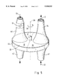
- FIG. 5 shows a rotating reactor
- the device 1 shown in FIGS. 1 and 2 for purifying an air stream 2 fed into the interior of a vehicle comprises two reactors 4 and 5 which are disposed in a housing 3, which are disposed in parallel to one another and between which a common main air chamber 6 is formed.
- the reactors 4, 5 are designed as flat wall elements, and each delineates by means of the other side a subsidiary air chambers 7 and 8 which extend in parallel to the longitudinal direction of the reactors.
- Each reactor 4, 5 forms an air-permeable wall between the subsidiary air chambers 7, 8 and the main air chamber 6.
- the main air chamber 6 and the subsidiary air chambers 7, 8 are open at their ends adjacent to an air inlet chamber 9.
- a heating device 10 for heating the air flow entering the main air chamber is provided at the inlet side of the main air chamber 6.
- each subsidiary air chamber 7, 8 and in the main air chamber 6 Disposed in each subsidiary air chamber 7, 8 and in the main air chamber 6 is an air control element 11, 12, 13 which is designed as a valve and which extends diagonally in the respective chamber 6, 7, 8 and can be swivelled about a swivelling axis S 1 , S 2 , S 3 in the center of the valve, with the result that the air flow control elements can be switched between the end positions determined by the diagonals of the air chambers 6, 7, 8. All the air flow control elements 11, 12, 13 are actuated simultaneously, preferably by a common drive.
- the air flow control valve 11 in the main air chamber 6 divides said chamber in each of the two possible positions into a front region 6' and a rear region 6".
- an air duct 15 Connected to an opening 14 in the region 6" of the main air chamber 6 is an air duct 15, which is not shown in the drawing and leads to the interior of the vehicle.
- air outlet openings 16, 17 are provided which are disposed at the ends situated remotely from the air inlet chamber and to which the air outlet ducts 16' and 17' are connected.
- the air outlet openings 16, 17 can be closed depending on the position of the air flow control elements 12, 13, one of the air outlet openings always being closed and the other open.
- a fan 18 Disposed on the housing 3 upstream of the air inlet chamber 9 is a fan 18 having a radial blower wheel 19 which sucks in air in accordance with the arrow 20 (this may be, for example, air removed from the interior of the vehicle) and generates an air flow through a diffuser 21 into the air inlet chamber 9.
- This air flow is divided up into an adsorption air flow 22 and a desorption air flow 23, which first flows through the heating device 10.
- the adsorption air flow 22 is fed through the reactor 4 and purified therein, said purification being an adsorption and/or absorption of noxious and aromatic substances.
- the adsorption air flow discharges from the reactor 4 into the region 6" of the main air chamber 6 and leaves the latter through the opening 14 and the air duct 15 as purified air flow 2, which is fed into the interior of the vehicle.
- the desorption air flow 23 enters the region 6' of the main air chamber 6, arriving from the heating device 10, and is fed through the reactor 5 because of the position of the air flow control element 11 and picks up therein the noxious and odorous substances deposited on the surface of the adsorber material.
- the desorption air flow leaving the reactor 5 discharges through the outlet air opening 17 disposed in the subsidiary air chamber 8 and is discharged into the surrounding air. If the air flow control elements 11, 12 and 13 are set to the second possible position, as is shown in FIG.
- the reactor 5 serves to purify the adsorption air stream 22 which enters the region 6" of the main air chamber 6 from the subsidiary air chamber 8 and is fed from there to the interior of the vehicle as purified air flow 2.
- the desorption air flow 23 is fed through the reactor 4 into the subsidiary air chamber 7 and discharges through the air outlet opening 16 and the air outlet duct 16'.
- the device shown in FIGS. 3 and 4 differs from the one described above in that the subsidiary air chambers 7 and 8 are not connected to the air inlet chamber 9 but are exposed to a separate air flow.
- the entire arrangement is disposed in an air feed duct 25 into which is fed air from the interior of the vehicle in accordance with arrows 26.
- a particle filter 27 is provided to remove coarse contaminants in the airstream, so that the adsorption air stream does not load the reactor 4 or 5 with dirt.
- An air duct 29 connected to the outside of the vehicle leads to the intake region of a fan 30, which serves solely to generate the desorption air flow 23. It is also possible to dispose a particle filter in the air duct 29 so that the dirt present in the outside air does not load the reactor.
- the operation of the device is the same as that described in connection with FIGS. 1 and 2, so that reference is made to the details relating to them.
- FIG. 5 shows a rotating reactor 32 which can be used instead of the stationary reactors 4 and 5 shown in FIGS. 3 and 4.
- the reactor 32 which has the shape of a disk, is disposed in a housing 33 which is subdivided into a chamber 35 for the adsorption air flow and a chamber 36 for the desorption air flow.
- the reactor forms an air-permeable flat wall element extending transversely with respect to the air flow direction.
- the reactor has a drive shaft 37 by means of which the reactor is moved around the axis of rotation 38 in the direction of the arrow 39.
- the adsorption air stream 22 enters the chamber through a connecting pipe piece 41 and is purified by a reactor section disposed in said chamber in order then to be fed into the interior of the vehicle through an air feed duct 34 as purified air flow 2.
- the desorption air flow 23 is first fed through the heating device 10 and then through a connecting pipe piece 40 of the chamber 36 for the desorption air flow.
- the noxious substances deposited in the adsorption material are picked up from the reactor section disposed in said chamber 36 and fed through an outlet air duct 42 into the open air.
- the devices described above are able to pick up various noxious and aromatic substances depending on the type of adsorber material, the mixture or combination of various materials substantially increasing the spectrum of the types of substances eliminated.
- the substances to be removed mention may be made, in particular, of hydrocarbons, such as ether and benzenes, and also alcohols, hydrogen sulfides, amines, ammonia, nicotine, carboxylic acid, halides and methylene chloride.
- hydrocarbons such as ether and benzenes
- alcohols hydrogen sulfides, amines, ammonia, nicotine, carboxylic acid, halides and methylene chloride.
- all the exhaust-gas constituents which vehicles discharge into the air are also filtered out by the device, as are their reaction products, of which mention should be made, in particular, of ozone.
- the purification of the air fed into the interior of the vehicle is an important contribution to the well-being of the vehicle passengers and, in addition, increases traffic safety since, because of the removal of moisture from the absorption air flow, dry air is fed into the interior of the vehicle and consequently condensation on the windows is avoided.
Abstract
Description
Claims (26)
Applications Claiming Priority (3)
| Application Number | Priority Date | Filing Date | Title |
|---|---|---|---|
| DE4427793 | 1994-08-08 | ||
| DE4427793A DE4427793C2 (en) | 1994-08-08 | 1994-08-08 | Device for removing the harmful and aromatic substances from an air flow supplied to the vehicle interior |
| PCT/EP1995/003024 WO1996005079A1 (en) | 1994-08-08 | 1995-07-29 | Device for removing noxious and aromatic matter from an air flow into the interior of a vehicle |
Publications (1)
| Publication Number | Publication Date |
|---|---|
| US5938523A true US5938523A (en) | 1999-08-17 |
Family
ID=6525027
Family Applications (1)
| Application Number | Title | Priority Date | Filing Date |
|---|---|---|---|
| US08/776,650 Expired - Fee Related US5938523A (en) | 1994-08-08 | 1995-07-29 | Device for removing the noxious and aromatic substances from an air flow fed into the interior of a vehicle |
Country Status (6)
| Country | Link |
|---|---|
| US (1) | US5938523A (en) |
| EP (1) | EP0775060B1 (en) |
| JP (1) | JP3808096B2 (en) |
| DE (2) | DE4427793C2 (en) |
| ES (1) | ES2126306T3 (en) |
| WO (1) | WO1996005079A1 (en) |
Cited By (30)
| Publication number | Priority date | Publication date | Assignee | Title |
|---|---|---|---|---|
| US6364942B1 (en) * | 2000-03-06 | 2002-04-02 | Honeywell International Inc. | Dehumidifier using non-rotating desiccant material |
| WO2002070110A2 (en) * | 2001-03-06 | 2002-09-12 | Engelhard Corporation | Vehicular atomsphere cleansing system |
| WO2003000386A1 (en) * | 2001-06-20 | 2003-01-03 | Gerd Gaiser | Passenger compartment adsorption filter with cyclic regeneration for motor vehicles |
| US6530973B2 (en) * | 2001-01-16 | 2003-03-11 | Visteion Global Technologies, Inc. | Air desiccant system and method for automotive climate control |
| US6575228B1 (en) | 2000-03-06 | 2003-06-10 | Mississippi State Research And Technology Corporation | Ventilating dehumidifying system |
| US6595432B2 (en) * | 2000-03-22 | 2003-07-22 | Webasto Thermosysteme International Gmbh | Heating system for heating the passenger compartment of an automobile |
| EP1344669A4 (en) * | 2000-06-07 | 2003-09-17 | Anatoly Anatolyevich Kutyev | Method for removing harmful impurities from the air and device for carrying out said method |
| EP1518731A1 (en) * | 2003-09-24 | 2005-03-30 | Behr GmbH & Co. KG | Unit with fan and filter |
| US20050124286A1 (en) * | 2003-12-09 | 2005-06-09 | Valeo Climate Control Corp. | Method and apparatus for decontamination for automotive HVAC systems |
| US20060107835A1 (en) * | 2004-11-17 | 2006-05-25 | Mann & Hummel Gmbh | Air conducting channel |
| US20070057224A1 (en) * | 2003-09-05 | 2007-03-15 | R-Amtech International, Inc. | Composition for cooling and simultaneous filtration of the gas-aerosol fire-extinguishing mixture |
| FR2958221A1 (en) * | 2010-03-31 | 2011-10-07 | Valeo Systemes Thermiques | Ventilation, heating and/or air-conditioning installation for motor vehicle, has case equipped with filter to retain pollutants conveyed by air flows, where filter is rotatably assembled around rotation axis inside wall of case |
| US20120222559A1 (en) * | 2011-03-01 | 2012-09-06 | Faurecia Interior Systems, Inc. | Air channel with integrated odor absorbing element |
| US20130240173A1 (en) * | 2012-03-13 | 2013-09-19 | Ford Global Technologies, Llc | Climate Control System for a Vehicle and a Method of Control |
| CN103625240A (en) * | 2012-08-27 | 2014-03-12 | 福特环球技术公司 | Motor vehicle climate control system |
| US20140326133A1 (en) * | 2013-05-01 | 2014-11-06 | Ford Global Technologies, Llc | Climate Control System Having Multiple Adsorbers and a Method of Control |
| GB2521450A (en) * | 2013-12-20 | 2015-06-24 | Jaguar Land Rover Ltd | A system for conditioning air and a filtering apparatus therefor |
| US20150283880A1 (en) * | 2014-04-02 | 2015-10-08 | Volvo Car Corporation | Vehicle ambient air purification arrangement and method, and a vehicle and vehicle fleet comprising such arrangement |
| WO2016005401A1 (en) * | 2014-07-09 | 2016-01-14 | Cnh Industrial Italia S.P.A. | Selective filtration level air treatment system. |
| WO2016005406A1 (en) * | 2014-07-09 | 2016-01-14 | Cnh Industrial Italia S.P.A. | Air treatment system with pressure balance |
| US20180156481A1 (en) * | 2009-12-31 | 2018-06-07 | David J. Carpenter | Displacement ventilation systems for enclosed spaces |
| US10232685B2 (en) * | 2017-02-03 | 2019-03-19 | Ford Global Technologies, Llc | Automotive interior air quality carbon canister status and replacement/regeneration control |
| US10279658B2 (en) | 2014-09-29 | 2019-05-07 | Ford Global Technologies, Llc | Vehicle VOC reduction system |
| US10323850B2 (en) * | 2014-08-05 | 2019-06-18 | Corroventa Avfuktning Ab | Method and device for dehumidification |
| US10336162B2 (en) * | 2017-06-27 | 2019-07-02 | Ford Global Technologies Llc | HVAC system with odor absorbent regeneration |
| US10350536B2 (en) * | 2016-11-09 | 2019-07-16 | Climate By Design International, Inc. | Reverse flow dehumidifier and methods of operating the same |
| CN111251839A (en) * | 2018-11-30 | 2020-06-09 | 本田技研工业株式会社 | Air purifying device |
| US11260345B2 (en) * | 2019-12-11 | 2022-03-01 | Institute of Nuclear Energy Research, Atomic Energy Council, Executive Yuan, R.O.C. | High-efficiency desiccant wheel |
| US11292319B2 (en) * | 2019-03-28 | 2022-04-05 | GM Global Technology Operations LLC | Operation of a HVAC system to desorb a filter |
| US20220226767A1 (en) * | 2021-01-19 | 2022-07-21 | Honda Motor Co., Ltd. | Vehicle air purification system and method of controlling vehicle air purification system |
Families Citing this family (15)
| Publication number | Priority date | Publication date | Assignee | Title |
|---|---|---|---|---|
| DE19512844A1 (en) * | 1995-04-06 | 1996-10-10 | Behr Gmbh & Co | Device and method for treating an air flow supplied to an interior |
| FR2749806B1 (en) * | 1996-06-14 | 1998-08-14 | Valeo Climatisation | HEATING, VENTILATION AND / OR AIR CONDITIONING SYSTEM WITH INTEGRATED AIR FILTER, ESPECIALLY FOR MOTOR VEHICLES |
| DE19624216B4 (en) * | 1996-06-18 | 2005-04-28 | Behr Gmbh & Co Kg | Device and method for the treatment of a vehicle interior supplied air flow |
| DE19637232A1 (en) * | 1996-09-13 | 1998-03-19 | Behr Gmbh & Co | Device and method for controlling air guiding elements of a vehicle |
| DE19645823A1 (en) * | 1996-11-07 | 1998-05-14 | Behr Gmbh & Co | Automotive passenger cabin air cleaner |
| DE19653964A1 (en) * | 1996-12-21 | 1998-06-25 | Behr Gmbh & Co | Air conditioning unit for vehicle interior equipped for filtration, moisture adsorption and regeneration |
| DE19720837A1 (en) * | 1997-05-17 | 1998-11-19 | Behr Gmbh & Co | Motor vehicle heating method |
| DE19734440C1 (en) * | 1997-08-08 | 1998-09-03 | Behr Gmbh & Co | Air treatment unit for vehicle interior air supply |
| DE19914614B4 (en) * | 1999-03-31 | 2007-09-13 | Behr Gmbh & Co. Kg | Apparatus and method for cleaning an airflow supplied to the vehicle interior |
| DE10033806A1 (en) * | 2000-07-12 | 2002-01-24 | Behr Gmbh & Co | Air conditioning unit for fitting to a motor vehicle has a casing, a fan, air filters cleaned by desorption, a cooling unit/vaporizer, a heating unit and a drain channel for running off condensed water |
| ATE517296T1 (en) * | 2007-12-21 | 2011-08-15 | Akos Advanced Technology Ltd | AIR PURIFICATION SYSTEM |
| US9737841B2 (en) | 2007-12-21 | 2017-08-22 | Sui Chun Law | Air purification system |
| DE102010038958A1 (en) * | 2010-08-05 | 2012-02-09 | Behr Gmbh & Co. Kg | Filter system for motor vehicle, particularly for cleaning of polluted air or outside air or inside air, has air channel and filter unit, particularly hybrid filter unit, where filter element is formed as high performance adsorber element |
| CN106377975A (en) * | 2016-11-17 | 2017-02-08 | 南京大学环境规划设计研究院有限公司 | Automotive air purifier and purification method thereof |
| FR3062604B1 (en) * | 2017-02-08 | 2019-04-05 | Renault S.A.S. | HEATING / AIR CONDITIONING SYSTEM WITH PERFORMING AIR TREATMENT DEVICE |
Citations (15)
| Publication number | Priority date | Publication date | Assignee | Title |
|---|---|---|---|---|
| US2248225A (en) * | 1937-08-27 | 1941-07-08 | Bryant Heater Co | Dehumidifier |
| US2257478A (en) * | 1938-10-22 | 1941-09-30 | Honeywell Regulator Co | Air conditioning system |
| US2946201A (en) * | 1960-07-26 | Method for avoiding frost deposits on cooling members | ||
| US3263400A (en) * | 1963-07-16 | 1966-08-02 | Exxon Research Engineering Co | Air treatment |
| US3368327A (en) * | 1964-07-08 | 1968-02-13 | Munters Carl Georg | Regenerative moisture exchanger for gaseous media |
| GB1211101A (en) * | 1966-11-26 | 1970-11-04 | Amec Handels Gmbh & Co K G | Apparatus for the recovery of solvents from the air |
| US4259092A (en) * | 1976-03-23 | 1981-03-31 | Toyo Boseki Kabushiki Kaisha | Adsorptive material |
| US4290789A (en) * | 1979-03-08 | 1981-09-22 | Wing Industries, Inc. | Total energy exchange apparatus |
| DE3626887A1 (en) * | 1986-08-08 | 1988-02-11 | Miele & Cie | Laundry machine and dishwasher, oven or the like, with a dehumidifier |
| US5222375A (en) * | 1991-08-20 | 1993-06-29 | Conrad Wayne E | Adsorption/humidification cooler for humid gaseous fluids |
| US5464468A (en) * | 1993-06-03 | 1995-11-07 | Taikisha Ltd. | Rotary adsorption/desorption gas treating apparatus |
| US5542968A (en) * | 1995-01-24 | 1996-08-06 | Laroche Industries, Inc. | Enthalphy Wheel |
| US5580370A (en) * | 1992-05-03 | 1996-12-03 | Kabushiki Kaisha Seibu Giken | Total heat energy exchanger element preventing a transfer of odors and method of manufacturing same |
| US5620367A (en) * | 1994-03-15 | 1997-04-15 | Behr Gmbh & Co. | Air drying installation for motor vehicles |
| US5667560A (en) * | 1993-10-25 | 1997-09-16 | Uop | Process and apparatus for dehumidification and VOC odor remediation |
Family Cites Families (12)
| Publication number | Priority date | Publication date | Assignee | Title |
|---|---|---|---|---|
| US3827218A (en) * | 1972-08-31 | 1974-08-06 | Ajax Magnethermic Corp | Valveless low pressure air dehumidifier |
| DE3100915C2 (en) * | 1980-05-26 | 1986-08-07 | Sharp K.K., Osaka | Air conditioning unit for recirculation mode |
| DE3334992A1 (en) * | 1983-09-28 | 1985-04-25 | Daimler-Benz Ag, 7000 Stuttgart | METHOD AND DEVICE FOR REMOVING ODOR SUBSTANCES FROM THE AIR OF VEHICLE CABINS |
| DE3514038A1 (en) * | 1985-04-18 | 1986-10-23 | Hölter, Heinz, Dipl.-Ing., 4390 Gladbeck | Elastic packed bed filters for vehicles |
| DE3517105C1 (en) * | 1985-05-11 | 1985-11-28 | Daimler-Benz Ag, 7000 Stuttgart | Process for removing constituents from a gas stream by adsorption onto activated charcoal |
| DE3532463A1 (en) * | 1985-09-11 | 1987-03-19 | Sueddeutsche Kuehler Behr | HEATING AND / OR AIR CONDITIONING FOR MOTOR VEHICLES |
| DE3545664A1 (en) * | 1985-12-21 | 1987-07-02 | Knecht Filterwerke Gmbh | Ventilation device for closed rooms |
| US5085049A (en) * | 1990-07-09 | 1992-02-04 | Rim Julius J | Diesel engine exhaust filtration system and method |
| DE4023995C2 (en) * | 1990-07-28 | 1994-06-09 | Pcp Photocatalytic Purificatio | Method and device for fresh air and indoor air purification in motor vehicles |
| DE4030144C1 (en) * | 1990-09-24 | 1992-04-23 | Mercedes-Benz Aktiengesellschaft, 7000 Stuttgart, De | |
| DE4105724C2 (en) * | 1991-02-23 | 1993-10-21 | Daimler Benz Ag | Ventilation device for the interior of a vehicle, in particular heating or air conditioning for a motor vehicle |
| DE4140942A1 (en) * | 1991-12-12 | 1992-12-03 | Daimler Benz Ag | Regeneratable soot filter for diesel engine exhaust system - has rotary disc element with two sectors exposed alternately to exhaust gas and soot-combustion air |
-
1994
- 1994-08-08 DE DE4427793A patent/DE4427793C2/en not_active Expired - Fee Related
-
1995
- 1995-07-29 JP JP50696496A patent/JP3808096B2/en not_active Expired - Fee Related
- 1995-07-29 ES ES95928491T patent/ES2126306T3/en not_active Expired - Lifetime
- 1995-07-29 WO PCT/EP1995/003024 patent/WO1996005079A1/en active IP Right Grant
- 1995-07-29 EP EP95928491A patent/EP0775060B1/en not_active Expired - Lifetime
- 1995-07-29 US US08/776,650 patent/US5938523A/en not_active Expired - Fee Related
- 1995-07-29 DE DE59504700T patent/DE59504700D1/en not_active Expired - Fee Related
Patent Citations (15)
| Publication number | Priority date | Publication date | Assignee | Title |
|---|---|---|---|---|
| US2946201A (en) * | 1960-07-26 | Method for avoiding frost deposits on cooling members | ||
| US2248225A (en) * | 1937-08-27 | 1941-07-08 | Bryant Heater Co | Dehumidifier |
| US2257478A (en) * | 1938-10-22 | 1941-09-30 | Honeywell Regulator Co | Air conditioning system |
| US3263400A (en) * | 1963-07-16 | 1966-08-02 | Exxon Research Engineering Co | Air treatment |
| US3368327A (en) * | 1964-07-08 | 1968-02-13 | Munters Carl Georg | Regenerative moisture exchanger for gaseous media |
| GB1211101A (en) * | 1966-11-26 | 1970-11-04 | Amec Handels Gmbh & Co K G | Apparatus for the recovery of solvents from the air |
| US4259092A (en) * | 1976-03-23 | 1981-03-31 | Toyo Boseki Kabushiki Kaisha | Adsorptive material |
| US4290789A (en) * | 1979-03-08 | 1981-09-22 | Wing Industries, Inc. | Total energy exchange apparatus |
| DE3626887A1 (en) * | 1986-08-08 | 1988-02-11 | Miele & Cie | Laundry machine and dishwasher, oven or the like, with a dehumidifier |
| US5222375A (en) * | 1991-08-20 | 1993-06-29 | Conrad Wayne E | Adsorption/humidification cooler for humid gaseous fluids |
| US5580370A (en) * | 1992-05-03 | 1996-12-03 | Kabushiki Kaisha Seibu Giken | Total heat energy exchanger element preventing a transfer of odors and method of manufacturing same |
| US5464468A (en) * | 1993-06-03 | 1995-11-07 | Taikisha Ltd. | Rotary adsorption/desorption gas treating apparatus |
| US5667560A (en) * | 1993-10-25 | 1997-09-16 | Uop | Process and apparatus for dehumidification and VOC odor remediation |
| US5620367A (en) * | 1994-03-15 | 1997-04-15 | Behr Gmbh & Co. | Air drying installation for motor vehicles |
| US5542968A (en) * | 1995-01-24 | 1996-08-06 | Laroche Industries, Inc. | Enthalphy Wheel |
Cited By (52)
| Publication number | Priority date | Publication date | Assignee | Title |
|---|---|---|---|---|
| US6575228B1 (en) | 2000-03-06 | 2003-06-10 | Mississippi State Research And Technology Corporation | Ventilating dehumidifying system |
| US6364942B1 (en) * | 2000-03-06 | 2002-04-02 | Honeywell International Inc. | Dehumidifier using non-rotating desiccant material |
| US6595432B2 (en) * | 2000-03-22 | 2003-07-22 | Webasto Thermosysteme International Gmbh | Heating system for heating the passenger compartment of an automobile |
| EP1344669A1 (en) * | 2000-06-07 | 2003-09-17 | Anatoly Anatolyevich Kutyev | Method for removing harmful impurities from the air and device for carrying out said method |
| EP1344669A4 (en) * | 2000-06-07 | 2003-09-17 | Anatoly Anatolyevich Kutyev | Method for removing harmful impurities from the air and device for carrying out said method |
| US6530973B2 (en) * | 2001-01-16 | 2003-03-11 | Visteion Global Technologies, Inc. | Air desiccant system and method for automotive climate control |
| WO2002070110A3 (en) * | 2001-03-06 | 2002-11-07 | Engelhard Corp | Vehicular atomsphere cleansing system |
| WO2002070110A2 (en) * | 2001-03-06 | 2002-09-12 | Engelhard Corporation | Vehicular atomsphere cleansing system |
| US20040020359A1 (en) * | 2001-03-06 | 2004-02-05 | Engelhard Corporation | Vehicular atmosphere cleansing system |
| US7080505B2 (en) | 2001-03-06 | 2006-07-25 | Engelhard Corporation | Vehicular atmosphere cleansing method |
| WO2003000386A1 (en) * | 2001-06-20 | 2003-01-03 | Gerd Gaiser | Passenger compartment adsorption filter with cyclic regeneration for motor vehicles |
| US20070057224A1 (en) * | 2003-09-05 | 2007-03-15 | R-Amtech International, Inc. | Composition for cooling and simultaneous filtration of the gas-aerosol fire-extinguishing mixture |
| EP1518731A1 (en) * | 2003-09-24 | 2005-03-30 | Behr GmbH & Co. KG | Unit with fan and filter |
| US20050124286A1 (en) * | 2003-12-09 | 2005-06-09 | Valeo Climate Control Corp. | Method and apparatus for decontamination for automotive HVAC systems |
| US6991532B2 (en) | 2003-12-09 | 2006-01-31 | Valeo Climate Control Corp. | Method and apparatus for decontamination for automotive HVAC systems |
| US20060107835A1 (en) * | 2004-11-17 | 2006-05-25 | Mann & Hummel Gmbh | Air conducting channel |
| US20180156481A1 (en) * | 2009-12-31 | 2018-06-07 | David J. Carpenter | Displacement ventilation systems for enclosed spaces |
| US11268710B2 (en) * | 2009-12-31 | 2022-03-08 | David J. Carpenter | Displacement ventilation systems for enclosed spaces |
| FR2958221A1 (en) * | 2010-03-31 | 2011-10-07 | Valeo Systemes Thermiques | Ventilation, heating and/or air-conditioning installation for motor vehicle, has case equipped with filter to retain pollutants conveyed by air flows, where filter is rotatably assembled around rotation axis inside wall of case |
| US20120222559A1 (en) * | 2011-03-01 | 2012-09-06 | Faurecia Interior Systems, Inc. | Air channel with integrated odor absorbing element |
| US8500890B2 (en) * | 2011-03-01 | 2013-08-06 | Faurecia Interior Systems, Inc. | Air channel with integrated odor absorbing element |
| US10343497B2 (en) | 2012-03-13 | 2019-07-09 | Ford Global Technologies, Llc | Method of controlling a climate control system |
| US20130240173A1 (en) * | 2012-03-13 | 2013-09-19 | Ford Global Technologies, Llc | Climate Control System for a Vehicle and a Method of Control |
| US9266407B2 (en) * | 2012-03-13 | 2016-02-23 | Ford Global Technologies, Llc | Climate control system for a vehicle and a method of control |
| CN103625240A (en) * | 2012-08-27 | 2014-03-12 | 福特环球技术公司 | Motor vehicle climate control system |
| CN103625240B (en) * | 2012-08-27 | 2017-05-03 | 福特环球技术公司 | Motor vehicle climate control system |
| US9080796B2 (en) * | 2012-08-27 | 2015-07-14 | Ford Global Technologies, Llc | Motor vehicle climate control system |
| US9028591B2 (en) * | 2013-05-01 | 2015-05-12 | Ford Global Technologies, Llc | Climate control system having multiple adsorbers and a method of control |
| US20140326133A1 (en) * | 2013-05-01 | 2014-11-06 | Ford Global Technologies, Llc | Climate Control System Having Multiple Adsorbers and a Method of Control |
| GB2521450B (en) * | 2013-12-20 | 2017-02-15 | Jaguar Land Rover Ltd | A system for conditioning air and a filtering apparatus therefor |
| GB2521450A (en) * | 2013-12-20 | 2015-06-24 | Jaguar Land Rover Ltd | A system for conditioning air and a filtering apparatus therefor |
| US20150283880A1 (en) * | 2014-04-02 | 2015-10-08 | Volvo Car Corporation | Vehicle ambient air purification arrangement and method, and a vehicle and vehicle fleet comprising such arrangement |
| US10682895B2 (en) * | 2014-04-02 | 2020-06-16 | Volvo Car Corporation | Vehicle ambient air purification arrangement and method, and a vehicle and vehicle fleet comprising such arrangement |
| WO2016005401A1 (en) * | 2014-07-09 | 2016-01-14 | Cnh Industrial Italia S.P.A. | Selective filtration level air treatment system. |
| WO2016005406A1 (en) * | 2014-07-09 | 2016-01-14 | Cnh Industrial Italia S.P.A. | Air treatment system with pressure balance |
| US10300761B2 (en) * | 2014-07-09 | 2019-05-28 | Cnh Industrial America Llc | Air treatment system with pressure balance |
| AU2015286813B2 (en) * | 2014-07-09 | 2017-11-16 | Cnh Industrial Italia S.P.A. | Air treatment system with pressure balance |
| AU2015286808B2 (en) * | 2014-07-09 | 2018-02-22 | Cnh Industrial Italia S.P.A. | Selective filtration level air treatment system. |
| US20170210195A1 (en) * | 2014-07-09 | 2017-07-27 | Cnh Industrial America Llc | Air treatment system with pressure balance |
| US10752094B2 (en) | 2014-07-09 | 2020-08-25 | Cnh Industrial America Llc | Selective filtration level air treatment system |
| AU2015286813C1 (en) * | 2014-07-09 | 2020-09-24 | Cnh Industrial Italia S.P.A. | Air treatment system with pressure balance |
| US10323850B2 (en) * | 2014-08-05 | 2019-06-18 | Corroventa Avfuktning Ab | Method and device for dehumidification |
| US10279658B2 (en) | 2014-09-29 | 2019-05-07 | Ford Global Technologies, Llc | Vehicle VOC reduction system |
| US10350536B2 (en) * | 2016-11-09 | 2019-07-16 | Climate By Design International, Inc. | Reverse flow dehumidifier and methods of operating the same |
| US10232685B2 (en) * | 2017-02-03 | 2019-03-19 | Ford Global Technologies, Llc | Automotive interior air quality carbon canister status and replacement/regeneration control |
| US10336162B2 (en) * | 2017-06-27 | 2019-07-02 | Ford Global Technologies Llc | HVAC system with odor absorbent regeneration |
| CN111251839A (en) * | 2018-11-30 | 2020-06-09 | 本田技研工业株式会社 | Air purifying device |
| US11370276B2 (en) * | 2018-11-30 | 2022-06-28 | Honda Motor Co., Ltd. | Air purification device |
| US11292319B2 (en) * | 2019-03-28 | 2022-04-05 | GM Global Technology Operations LLC | Operation of a HVAC system to desorb a filter |
| US11260345B2 (en) * | 2019-12-11 | 2022-03-01 | Institute of Nuclear Energy Research, Atomic Energy Council, Executive Yuan, R.O.C. | High-efficiency desiccant wheel |
| US20220226767A1 (en) * | 2021-01-19 | 2022-07-21 | Honda Motor Co., Ltd. | Vehicle air purification system and method of controlling vehicle air purification system |
| US11684889B2 (en) * | 2021-01-19 | 2023-06-27 | Honda Motor Co., Ltd. | Vehicle air purification system and method of controlling vehicle air purification system |
Also Published As
| Publication number | Publication date |
|---|---|
| DE4427793A1 (en) | 1996-02-15 |
| WO1996005079A1 (en) | 1996-02-22 |
| JPH10510776A (en) | 1998-10-20 |
| ES2126306T3 (en) | 1999-03-16 |
| EP0775060A1 (en) | 1997-05-28 |
| EP0775060B1 (en) | 1998-12-30 |
| DE4427793C2 (en) | 1997-01-30 |
| DE59504700D1 (en) | 1999-02-11 |
| JP3808096B2 (en) | 2006-08-09 |
Similar Documents
| Publication | Publication Date | Title |
|---|---|---|
| US5938523A (en) | Device for removing the noxious and aromatic substances from an air flow fed into the interior of a vehicle | |
| US8263012B2 (en) | Photocatalyst protection | |
| KR102267883B1 (en) | A device for purifying the CO2-filled air in the cabin of a car in recirculation-air mode by means of an adsorption device | |
| JP2841140B2 (en) | Ventilation system for vehicle interior space | |
| US8366803B2 (en) | Air cleaner having regenerative filter, and method for regenerative of air cleaner filter | |
| JP2001500787A (en) | Method and apparatus for removing gaseous organic matter from air | |
| JP3050810B2 (en) | Air drying equipment | |
| JPH0920133A (en) | Equipment and method of treating air flow fed into chamber | |
| CN110871014A (en) | CO with moving bed structure2Washing device | |
| WO2001036880A1 (en) | Clean room | |
| JPH06101864A (en) | Air cleaner | |
| EP1344669B1 (en) | Method for removing harmful impurities from the air and device for carrying out said method | |
| US20060153747A1 (en) | Gas treatment adsorption-oxidation system | |
| JP2006239564A (en) | Voc removal system | |
| JPH05237342A (en) | Purifier of gas | |
| JP4873950B2 (en) | Automotive air purification system | |
| JP2002085934A (en) | Adsorption and desorption apparatus | |
| JP2002273148A (en) | Humidistat | |
| TW202400288A (en) | Exhaust gas treatment system | |
| JP2023059419A (en) | Air conditioning apparatus, air conditioning system, and adsorbent regeneration method | |
| JPH0141086B2 (en) | ||
| JP2001046478A (en) | Air cleaning device and air conditioning system |
Legal Events
| Date | Code | Title | Description |
|---|---|---|---|
| AS | Assignment |
Owner name: BEHR GMBH & CO., GERMANY Free format text: ASSIGNMENT OF ASSIGNORS INTEREST;ASSIGNORS:KHELIFA, NOUREDDINE;ABERSFELDER, GUENTER;REEL/FRAME:008529/0782;SIGNING DATES FROM 19970109 TO 19970117 Owner name: MERCEDES-BENZ AKTIENGESELLSCHAFT, GERMANY Free format text: ASSIGNMENT OF ASSIGNORS INTEREST;ASSIGNORS:KHELIFA, NOUREDDINE;ABERSFELDER, GUENTER;REEL/FRAME:008529/0782;SIGNING DATES FROM 19970109 TO 19970117 |
|
| FEPP | Fee payment procedure |
Free format text: PAYOR NUMBER ASSIGNED (ORIGINAL EVENT CODE: ASPN); ENTITY STATUS OF PATENT OWNER: LARGE ENTITY |
|
| FPAY | Fee payment |
Year of fee payment: 4 |
|
| REMI | Maintenance fee reminder mailed | ||
| AS | Assignment |
Owner name: DAIMLERCHRYSLER AG, GERMANY Free format text: CHANGE OF NAME;ASSIGNOR:DAIMLER-BENZ AG;REEL/FRAME:013907/0487 Effective date: 19980916 |
|
| AS | Assignment |
Owner name: BEHR GMBH & CO., GERMANY Free format text: ASSIGNMENT OF ASSIGNORS INTEREST;ASSIGNOR:DAIMLERCHRYSLER AG;REEL/FRAME:013907/0950 Effective date: 20021028 |
|
| REMI | Maintenance fee reminder mailed | ||
| LAPS | Lapse for failure to pay maintenance fees | ||
| STCH | Information on status: patent discontinuation |
Free format text: PATENT EXPIRED DUE TO NONPAYMENT OF MAINTENANCE FEES UNDER 37 CFR 1.362 |
|
| FP | Lapsed due to failure to pay maintenance fee |
Effective date: 20070817 |