US5961536A - Catheter having a variable length balloon and method of using the same - Google Patents
Catheter having a variable length balloon and method of using the same Download PDFInfo
- Publication number
- US5961536A US5961536A US08/950,520 US95052097A US5961536A US 5961536 A US5961536 A US 5961536A US 95052097 A US95052097 A US 95052097A US 5961536 A US5961536 A US 5961536A
- Authority
- US
- United States
- Prior art keywords
- balloon
- outer sleeve
- catheter shaft
- distal end
- sleeve
- Prior art date
- Legal status (The legal status is an assumption and is not a legal conclusion. Google has not performed a legal analysis and makes no representation as to the accuracy of the status listed.)
- Expired - Lifetime
Links
- 238000000034 method Methods 0.000 title claims description 23
- 239000003550 marker Substances 0.000 claims description 26
- 239000012530 fluid Substances 0.000 abstract description 11
- 238000004891 communication Methods 0.000 abstract description 7
- 239000000463 material Substances 0.000 description 38
- 230000014759 maintenance of location Effects 0.000 description 23
- -1 polyethylene Polymers 0.000 description 14
- 239000000853 adhesive Substances 0.000 description 12
- 230000001070 adhesive effect Effects 0.000 description 12
- 239000004698 Polyethylene Substances 0.000 description 10
- 229920000573 polyethylene Polymers 0.000 description 10
- 229910001220 stainless steel Inorganic materials 0.000 description 10
- 239000010935 stainless steel Substances 0.000 description 10
- 239000004677 Nylon Substances 0.000 description 6
- 229920001778 nylon Polymers 0.000 description 6
- 208000031481 Pathologic Constriction Diseases 0.000 description 5
- 238000010276 construction Methods 0.000 description 5
- 230000006870 function Effects 0.000 description 5
- HLXZNVUGXRDIFK-UHFFFAOYSA-N nickel titanium Chemical compound [Ti].[Ti].[Ti].[Ti].[Ti].[Ti].[Ti].[Ti].[Ti].[Ti].[Ti].[Ni].[Ni].[Ni].[Ni].[Ni].[Ni].[Ni].[Ni].[Ni].[Ni].[Ni].[Ni].[Ni].[Ni] HLXZNVUGXRDIFK-UHFFFAOYSA-N 0.000 description 5
- 229910001000 nickel titanium Inorganic materials 0.000 description 5
- 208000037804 stenosis Diseases 0.000 description 5
- 230000036262 stenosis Effects 0.000 description 5
- 239000004696 Poly ether ether ketone Substances 0.000 description 4
- 229920002614 Polyether block amide Polymers 0.000 description 4
- 230000008859 change Effects 0.000 description 4
- 230000003993 interaction Effects 0.000 description 4
- 229920002530 polyetherether ketone Polymers 0.000 description 4
- JOYRKODLDBILNP-UHFFFAOYSA-N Ethyl urethane Chemical compound CCOC(N)=O JOYRKODLDBILNP-UHFFFAOYSA-N 0.000 description 3
- 229920006099 Vestamid® Polymers 0.000 description 3
- 238000002399 angioplasty Methods 0.000 description 3
- 210000001367 artery Anatomy 0.000 description 3
- 230000010339 dilation Effects 0.000 description 3
- 239000013013 elastic material Substances 0.000 description 3
- 238000002594 fluoroscopy Methods 0.000 description 3
- 229920000642 polymer Polymers 0.000 description 3
- 230000008569 process Effects 0.000 description 3
- 230000002792 vascular Effects 0.000 description 3
- 239000004743 Polypropylene Substances 0.000 description 2
- 238000013459 approach Methods 0.000 description 2
- 210000004204 blood vessel Anatomy 0.000 description 2
- 239000004816 latex Substances 0.000 description 2
- 229920000126 latex Polymers 0.000 description 2
- 238000000465 moulding Methods 0.000 description 2
- 229920001155 polypropylene Polymers 0.000 description 2
- WFKWXMTUELFFGS-UHFFFAOYSA-N tungsten Chemical compound [W] WFKWXMTUELFFGS-UHFFFAOYSA-N 0.000 description 2
- 229910052721 tungsten Inorganic materials 0.000 description 2
- 239000010937 tungsten Substances 0.000 description 2
- 210000001635 urinary tract Anatomy 0.000 description 2
- 229920003182 Surlyn® Polymers 0.000 description 1
- 206010053648 Vascular occlusion Diseases 0.000 description 1
- 230000017531 blood circulation Effects 0.000 description 1
- 210000004351 coronary vessel Anatomy 0.000 description 1
- 230000000694 effects Effects 0.000 description 1
- 238000001125 extrusion Methods 0.000 description 1
- 229920005570 flexible polymer Polymers 0.000 description 1
- PCHJSUWPFVWCPO-UHFFFAOYSA-N gold Chemical compound [Au] PCHJSUWPFVWCPO-UHFFFAOYSA-N 0.000 description 1
- 229910052737 gold Inorganic materials 0.000 description 1
- 239000010931 gold Substances 0.000 description 1
- 238000004519 manufacturing process Methods 0.000 description 1
- 239000002184 metal Substances 0.000 description 1
- 229910052751 metal Inorganic materials 0.000 description 1
- 239000007769 metal material Substances 0.000 description 1
- 239000004417 polycarbonate Substances 0.000 description 1
- 229920000515 polycarbonate Polymers 0.000 description 1
- 229920002635 polyurethane Polymers 0.000 description 1
- 239000004814 polyurethane Substances 0.000 description 1
- 238000003825 pressing Methods 0.000 description 1
- 230000002787 reinforcement Effects 0.000 description 1
- 230000004044 response Effects 0.000 description 1
- 229910052710 silicon Inorganic materials 0.000 description 1
- 239000010703 silicon Substances 0.000 description 1
- 239000000126 substance Substances 0.000 description 1
- 230000001225 therapeutic effect Effects 0.000 description 1
- 208000019553 vascular disease Diseases 0.000 description 1
- 208000021331 vascular occlusion disease Diseases 0.000 description 1
Images


Classifications
-
- A—HUMAN NECESSITIES
- A61—MEDICAL OR VETERINARY SCIENCE; HYGIENE
- A61M—DEVICES FOR INTRODUCING MEDIA INTO, OR ONTO, THE BODY; DEVICES FOR TRANSDUCING BODY MEDIA OR FOR TAKING MEDIA FROM THE BODY; DEVICES FOR PRODUCING OR ENDING SLEEP OR STUPOR
- A61M25/00—Catheters; Hollow probes
- A61M25/10—Balloon catheters
- A61M2025/1043—Balloon catheters with special features or adapted for special applications
- A61M2025/1068—Balloon catheters with special features or adapted for special applications having means for varying the length or diameter of the deployed balloon, this variations could be caused by excess pressure
Definitions
- the present invention relates to a catheter having a variable length balloon. More particularly, it relates to a balloon catheter having an adjustment device for allowing adjustment of an effective balloon inflation length.
- Balloon catheters are widely used in a number of different applications.
- a balloon catheter is highly useful for effectuating and/or finalizing placement of a stent within the urinary tract, a blood vessel, biliary duct, etc., to name but a few.
- a balloon catheter can be used as part of an angioplasty procedure as an efficient and effective method for treating various types of vascular disease.
- angioplasty is widely used for opening a stenosis in a coronary artery, although it is also used for the treatment of a stenosis in other parts of the vascular system and other parts of the body.
- a balloon catheter In its most basic form, a balloon catheter generally includes a catheter shaft and an inflatable balloon.
- the catheter shaft defines an inflation lumen which extends to a distal end of the catheter shaft.
- the balloon in turn, is attached to the distal end of the catheter shaft such that an interior of the balloon is in fluid communication with the inflation lumen.
- Balloon inflation is achieved by supplying pressurized fluid to the inflation lumen that in turn inflates the balloon.
- the catheter shaft may include additional structure by which the balloon catheter can be directed to a particular site within the human body via a guidewire.
- the catheter shaft can be provided with other lumens for supplying specific therapeutic substances and/or instruments to the treatment site.
- the basic balloon catheter design includes a catheter shaft and a balloon fluidly connected to a distal end of the catheter shaft.
- a stent is placed over the balloon and delivered to a treatment site. Once properly in place, the balloon is inflated as previously described, causing the stent to expand and lodge against the walls of the particular duct being treated. This can be done as a follow-up to an angioplasty procedure. Alternatively, following stent placement, it may be necessary to re-expand or tack the stent against the duct walls. Once again, this procedure entails positioning the balloon, in a deflated state, within the stent and then inflating the balloon such that the balloon expands the stent.
- balloon inflation length is highly important.
- the balloon inflation length is selected to be slightly longer than the length of a selected stent so that the entire stent, including its ends, is expanded by the balloon.
- other recognized methods include choosing a balloon inflation length equal to or slightly smaller than that of the stent. It is believed that this technique achieves adequate stent extension while eliminating the opportunity for undesirable contact between the balloon and the duct wall.
- the standard balloon catheter design requires that a physician have on hand several catheters having different length balloons mounted thereon to accommodate different sized stents. Additionally, it may also require the physician to exchange catheters in the middle of a treatment process so that a catheter of proper balloon length can be utilized. Obviously, these factors can increase the cost of the particular procedure, along with the time required for treatment.
- the device is guided through the vascular system to a location near a stenosis.
- a physician guides the balloon catheter the remaining distance through the vascular system until the balloon is positioned across the stenosis.
- the balloon is then inflated by supplying fluid under pressure through the inflation lumen in the catheter to the balloon. Inflation of the balloon causes widening of the lumen of the artery to reestablish acceptable blood flow through the artery.
- Vascular occlusions to be treated by a balloon catheter can vary dramatically in size or length. With the variation in length of the occlusion, the area to be treated correspondingly varies in length. It is recognized as desirable to match the inflation length of the balloon as closely as possible to the length of the occlusion to be treated. This prevents expanding the balloon to a length otherwise resulting in pressing against a healthy artery wall. Similar to the drawbacks associated with stent application, the standard balloon catheter design requires, during a treatment, that a physician have on hand several catheters having different length balloons mounted thereon. It may also require the physician to exchange catheters in the middle of the treatment process so that a catheter of proper balloon length can be utilized.
- Fogarty et al. discloses a catheter including an elongated elastomeric tube closed at its distal end and extending the full length of the catheter.
- a telescopic sheath is received around the elastomeric tube, which has a distal primary section that is movable relative to the elastomeric tube and a proximal secondary section secured against movement relative to the elastomeric tube.
- a guidewire is disposed within and extends through the full length of the elastomeric tube with the guidewire having its distal end secured to the distal end of the tube, and its proximal end extending from the proximal end of the tube. The length of the balloon is thus adjusted by moving the distal primary section of the sheath while maintaining the position of the elastomeric tube and proximal secondary section of the sheath.
- Fogarty et al. discloses that the elastomeric tube may be stretched lengthwise to reduce its diametrical cross-section by extending the guidewire which is fixed to the distal end of the elastomeric tube.
- the fixing of the guidewire to the distal end of the elastomeric tube although aiding in adjusting the size of the balloon, prevents use as an over-the-wire device.
- the Fogarty et al. device requires that the telescopic sheath extend virtually the entire length of the elastomeric tube, increasing costs and opportunity for sheath movement. In other words, due to its length, the sheath can easily move upon inflation, creating unforeseen problems during use.
- the primary sheath is slidable relative to the secondary sheath, the primary sheath is free to move upon balloon inflation.
- Saab also discloses an adjustable-length balloon dilation catheter apparatus incorporating an adjustable sheath which is externally manipulated to partially surround and contain the dilation balloon segment of the catheter while the catheter balloon segments are expanded during a treatment procedure.
- Saab discloses an adjustable sheath which is substantially co-axial with the catheter and substantially surrounds the catheter body, balloon and catheter tip.
- the sheath may run the full length of the catheter or be provided at the distal end of a relatively stiff, controlled catheter, with the latter being co-axially mounted relative to the balloon catheter.
- the Saab device includes a sheath extending along virtually the entire catheter shaft, thus giving rise to many of the problems described above.
- the present invention is a balloon catheter including an adjustment device for adjusting an effective balloon inflation length.
- the balloon catheter generally includes a balloon in fluid communication with a distal end of a catheter shaft having a distal portion.
- the adjustment device includes an outer sleeve and an attachment means.
- the outer sleeve is configured to be generally co-axially received over the distal portion of the catheter shaft.
- at least a portion of the outer sleeve is configured to be slidable relative to the distal portion of the catheter shaft and the balloon such that a distal end of the outer sleeve can be positioned to restrict inflation of the balloon proximal the distal end of the outer sleeve.
- the attachment means is associated with the outer sleeve for selectively securing at least a portion of the outer sleeve to the distal portion of the catheter shaft such that positioning of the distal end of the outer sleeve at a desired location along the balloon length will not change upon inflation.
- a desired balloon inflation length is determined. This may entail reference to a particular stent length, stenosis size, etc.
- the outer sleeve is slid along the distal portion of the catheter shaft such that the distal end of the outer sleeve is positioned over the balloon at a location to restrict balloon inflation to an effective balloon inflation length equivalent to the desired length.
- the attachment means secures the outer sleeve in this position.
- the balloon catheter is then guided to the treatment site and the balloon inflated.
- the attachment means prevents movement of the outer sleeve following placement at the treatment site.
- the attachment means allows selective movement of the outer sleeve by a physician when the balloon catheter is not deployed such that the effective balloon inflation length can be changed.
- the attachment means includes a rib and a locking sleeve.
- the rib is attached to and concentrically extends from a circumference of the distal portion of the catheter shaft proximal the balloon.
- the locking sleeve is generally co-axially received over the outer sleeve and is configured to selectively secure the outer sleeve to the rib.
- the outer sleeve is maneuvered as previously described. Once properly positioned, the locking sleeve is positioned to engage the outer sleeve such that the outer sleeve is secured between the locking sleeve and the rib.
- a distal end of the outer sleeve is configured to allow at least partial inflation of the balloon both proximal and distal of the distal end such that the least partial inflation of the balloon assists in maintaining the position of the outer sleeve.
- Positioning of the outer sleeve can be changed by retracting the locking sleeve away from the rib, thereby freeing the outer sleeve to slide along the distal portion of the catheter shaft.
- FIG. 1 is a partial, longitudinal cross-sectional view of a balloon catheter including an adjustment device in accordance with the present invention
- FIGS. 2A and 2B are partial, longitudinal cross-sectional views of the distal portion of a balloon catheter including an alternative embodiment of an adjustment device in accordance with the present invention
- FIG. 3 is a partial, longitudinal cross-sectional view of the distal portion of a balloon catheter including an alternative embodiment of an adjustment device in accordance with the present invention
- FIGS. 4A and 4B are partial, longitudinal cross-sectional views of the distal portion of a balloon catheter including an alternative embodiment of an adjustment device in accordance with the present invention
- FIG. 5A is a partial, longitudinal cross-sectional view of the distal portion of a balloon catheter including an alternative embodiment of an adjustment device in accordance with the present invention
- FIGS. 5B and 5C are cross-sectional views of a portion of the balloon catheter of FIG. 5A, including a gripping body and catheter shaft;
- FIG. 6 is a partial, longitudinal cross-sectional view of the distal portion of a balloon catheter including an alternative embodiment of an adjustment device in accordance with the present invention
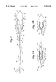
- FIG. 7 is a partial, longitudinal cross-sectional view of the distal portion of a balloon catheter including an alternative embodiment of an adjustment device in accordance with the present invention
- FIG. 8 is a partial, longitudinal cross-sectional view of the distal portion of a balloon catheter including an alternative embodiment of an adjustment device in accordance with the present invention.
- FIG. 9 is a partial, longitudinal cross-sectional view of the distal portion of a balloon catheter including an alternative embodiment of an adjustment device in accordance with the present invention.
- the balloon catheter assembly 20 includes a manifold 22, a catheter shaft 24, a balloon 26, a retention ring 28, a balloon adjustment sleeve 30, and a locking sleeve 32.
- the manifold 22 and the balloon 26 are fluidly connected at opposite ends of the catheter shaft 24.
- the retention ring 28 is disposed about an outer circumference of the catheter shaft 24.
- the balloon adjustment sleeve 30 is slidably disposed over the catheter shaft 24 and the balloon 26 in a generally co-axial fashion.
- the locking sleeve 32 is generally co-axially received over the balloon adjustment sleeve 30.
- the catheter shaft 24 is of a standard construction and includes a tubular body defined by a proximal portion 34 and a distal portion 36.
- the distal portion 36 is enlarged in FIG. 1.
- the proximal portion terminates in a proximal end 38.
- the distal portion 36 terminates at a distal end 40.
- the catheter shaft 24 includes an inflation lumen (not shown) extending from the proximal end 38 to the distal end 40.
- the catheter shaft 24 may also define additional lumens, such as a guidewire lumen (not shown).
- the catheter shaft can be an over-the-wire, fixed wire, single operator exchange, stent delivery, etc., catheter.
- the catheter shaft is preferably made from standard catheter material such as nylon.
- standard catheter material such as nylon.
- other materials such as polyethylene, polyurethane, polyethylene teraphthalate (PET), polyetheretherketone (PEEK), polyether block amide (PEBA), nylon, PEEK braid, SS hypotube, etc., may also be useful.
- the manifold 22 is of a standard construction and is attached to the proximal end 38 of the catheter shaft 24.
- the manifold 22 includes an inflation port 44 in fluid communication with the inflation lumen (not shown) of the catheter shaft 24.
- the manifold 22 is constructed from a polycarbonate material. Alternatively, other rigid materials may also be useful.
- the balloon 26 includes a proximal end 50, an intermediate portion 52 and a distal end 54.
- An inside diameter surface of the proximal end 50 is configured to be secured to an outside diameter surface of the distal end 40 of the catheter shaft 24 such that an interior of the balloon 26 is in fluid communication with the inflation lumen (not shown) of the catheter shaft 24.
- a preferred balloon material is PEBAX.
- PET polyethylene teraphthalate
- An adhesive may be utilized to secure the proximal end 50 of the balloon 26 to the distal end 40 of the catheter shaft 24.
- the retention ring 28 is configured to extend in a concentric fashion from an outer circumference of the distal portion 36 of the catheter shaft 24.
- the retention ring 28 includes an interior portion 60 and an exterior portion 62.
- the interior portion 60 is configured to be secured to the distal portion 36 of the catheter shaft 24 and is preferably made from nylon, such as VESTAMID from Huls America. Also, stainless steel could be used. Alternatively, other rigid materials may also be useful.
- the exterior portion 62 is fixed to the interior portion 60 as shown in FIG. 1 and preferably forms a circular outer surface.
- the exterior portion 62 is made of an elastic material such as urethane or latex and is fixed to the interior portion 60 by an adhesive.
- retention ring 28 has been preferably described as being a ring, other shapes may also be employed.
- the retention ring 28 may instead be a rib extending from the distal portion 36 of the catheter shaft 24 only partially about a circumference of the catheter shaft 24.
- the balloon adjustment sleeve 30 includes an outer sleeve 64, a stop collar 66 and a marker band 68.
- the outer sleeve 64 is defined by a proximal end 70, a proximal portion 72, a distal portion 74 and a distal end 76.
- the stop collar 66 is disposed at the proximal end 70 of the outer sleeve 64, whereas the marker band 68 is disposed at the distal end 76.
- the outer sleeve 64 is preferably tubular in shape, sized to be generally co-axially received over the distal portion 36 of the catheter shaft 24.
- the outer sleeve 64 has a diameter equal to or slightly larger than an outer diameter of the catheter shaft 24.
- the distal portion 74 of the outer sleeve 64 has a diameter slightly greater than a diameter of the proximal portion 72 of the outer sleeve 64.
- the distal portion 74 of the outer sleeve 64 has a diameter approximating an outer diameter of the retention ring 28.
- the outer sleeve 64 is preferably made of a semi-flexible material such as polyethylene teraphthalate (PET).
- PET polyethylene teraphthalate
- other similar materials such as NC PET, polyethylene, polypropylene, PEBAX, CRISTAMID, PEEK, etc., may also be useful.
- the stop collar 66 is preferably a ring having an inner diameter less than an outer diameter of the retention ring 28.
- the stop collar 66 is preferably made of a rigid material such as VESTAMID. Alternatively, other rigid materials such as stainless steel may also be useful.
- the stop collar 66 is preferably secured to the proximal end 70 of the outer sleeve 64 by an adhesive.
- the marker band 68 is preferably a ring-shaped body having an inner diameter slightly larger than the diameter of the balloon 26 when folded.
- the marker band 68 is constructed of a material visible utilizing fluoroscopy techniques. This configuration allows determination of balloon location during treatment.
- markings may be included on an outside surface of the catheter shaft 24 in the area of the distal end 40, or on the distal portion 36 of the catheter shaft 24, or on the balloon 26.
- the outer sleeve 64 can include a radiopaque loading, such as tungsten or gold.
- the marker band 68 also serves as a reinforcement to the distal end 76 of the outer sleeve 64.
- the marker band 68 further serves to prevent the outer sleeve 64 from sliding when the balloon 26 is inflated due to an inflated portion of the balloon both distal and proximal of the marker band 68.
- the marker band 68 is preferably configured as a relatively rigid shoulder to facilitate inflation restriction of the balloon 26 as described in greater detail below. Because the marker band 68 is in contact with the balloon 26 upon inflation, the marker band 68 preferably has a rounded interior surface. Alternatively, the marker band 68 may assume a conical shape.
- the locking sleeve 32 is a generally tubular body including a proximal portion 88 and a distal portion 90.
- the proximal portion 88 is preferably configured to have an inner diameter less than an outer diameter of the retention ring 28.
- the distal portion 90 as shown in FIG. 1, preferably expands in diameter from the proximal portion 88 to a distal end 92.
- the distal portion 90 preferably assumes a conical or funnel shape.
- the distal end 92 of the distal portion 90 preferably has a diameter approximating the outer diameter of the retention ring 28.
- the distal portion 90 need not be curved and may instead have a diameter slightly smaller than that of the retention ring 28.
- the locking sleeve 32 is made of a rigid material such as a VESTAMID. Alternatively, other rigid, surgically-safe materials such as polypropylene may also be useful. Regardless of exact form, the locking sleeve 32 is configured to slide over the balloon adjustment sleeve 30 and engage the retention ring 28.
- the above-described balloon catheter assembly 20 is constructed basically as follows.
- the retention ring 28 is secured to an exterior of the catheter shaft 24 along the distal portion 36 near the distal end 40.
- the balloon 26 is adhered to the distal end 40 of the catheter shaft 24 in fluid communication with the inflation lumen (not shown).
- the balloon adjustment sleeve 30 is slid in a co-axial fashion over the distal portion 36 of the catheter shaft 24 such that the distal end 76 of the outer sleeve 64 is distal the retention ring 28.
- the locking sleeve 32 is slid in a co-axial fashion over the balloon adjustment sleeve 30.
- the manifold 22 is secured to the proximal end 38 of the catheter shaft 24 such that the inflation port 44 is in fluid communication with the inflation lumen of the catheter shaft 24.
- the stop collar 66 preferably has a diameter less than an outer diameter of the retention ring 28.
- the stop collar 66 prevents the balloon adjustment sleeve 30 from sliding off of or otherwise disengaging from the distal end 40 of the catheter shaft 24.
- a desired balloon inflation length is first determined. For example, with stent delivery or tacking, a length of the stent (not shown) is ascertained.
- the balloon adjustment sleeve 30 is maneuvered relative to the distal portion 36 of the catheter shaft 24 and the balloon 26 to provide a balloon inflation length equivalent to the desired balloon inflation length.
- the locking sleeve 32 is retracted from engagement with the retention ring 28, toward the proximal end 38 of the catheter shaft 24.
- the balloon adjustment sleeve 30 is then free to slide over the distal portion 36 of the catheter shaft 24 and the balloon 26.
- the balloon 26 is preferably in a deflated state.
- the balloon adjustment sleeve 30 is slid to a position whereby the distal end 76 of the outer sleeve 64 encircles the balloon 26 at a position providing the effective balloon inflation length (designated as the length L1 in FIG. 1).
- the locking sleeve 32 With the balloon adjustment sleeve 30 properly positioned, the locking sleeve 32 is slid over the outer sleeve 64, toward the distal end 40 of the catheter shaft 24.
- the distal portion 90 of the locking sleeve 32 has a conical shape, reducing in diameter from the distal end 92 to the proximal portion 88.
- the distal portion 90 frictionally secures the outer sleeve 64 to the retention ring 28. In other words, the outer sleeve 64 is locked or pinched between the locking sleeve 32 and the retention ring 28.
- the exterior portion 62 of the retention ring 28 is preferably made of an elastic material to enhance frictional interaction between the outer sleeve 64 and the retention ring 28. In this secure position, the distal end 76 of the outer sleeve 64 is fixed relative to the balloon 26.
- the balloon catheter assembly 20 is ready for deployment.
- a stent (not shown) is crimped over the effective balloon inflation length L1 of the balloon 26.
- the balloon catheter assembly 20 is then guided to the treatment site.
- the balloon 26 is inflated via fluid supplied from the manifold 22 through the inflation lumen (not shown).
- the distal end 76 of the outer sleeve 64 restricts inflation of the balloon 26 proximal the distal end 76.
- the distal portion 74 in conjunction with the marker band 68 is preferably configured to maintain its shape to a pressure of at least 15-18 atmosphere.
- the distal portion 74 of the outer sleeve 64 has an inner diameter slightly larger than that of the marker band 68 of the outer sleeve 64.
- the distal portion 74 allows the balloon 26 to inflate slightly proximal the distal end 76 of the outer sleeve 64. This slight inflation assists in securing the balloon adjustment sleeve 30 in place as the balloon 26 inflates both distal and proximal of the marker band 68.
- inflation of the balloon along the effective balloon inflation length L1 applies a force against the distal end 76 of the outer sleeve 64 at the marker band 68.
- the marker band 68 functions as an annular shoulder, configured to allow at least partial inflation of the balloon 26 both proximal and distal of the marker band 68. This at least partial inflation holds the outer sleeve 64 in position to maintain the effective balloon inflation length L1.
- a similar procedure can be employed for other balloon catheter assembly 20 applications. For example, when the balloon catheter assembly 20 is to be used to expand or tack a previously-applied stent, a desired balloon inflation length is determined. The effective balloon inflation length L1 is then adjusted to accommodate this desired length by maneuvering and securing the balloon adjustment sleeve 30 as previously described. In other words, the balloon catheter assembly 20 allows a physician to adjust the effective balloon inflation length L1 to a length of the stent (not shown). Similarly, where the balloon catheter assembly 20 is to be used to enlarge a duct obstruction, such as in a blood vessel or urinary tract, the length of the obstruction is determined.
- the balloon adjustment sleeve 30 is then maneuvered and secured by the locking ring 32 to the retention ring 28 such that the distal end 76 of the outer sleeve 64 is positioned to provide an appropriate, effective balloon inflation length L1 matching the length of the obstruction.
- the above-described balloon catheter assembly 20 provides a variable length balloon catheter configured to allow physician adjustment of the outer sleeve 64 along the distal portion 36 of the catheter shaft 24 to alter the effective balloon inflation length.
- the outer sleeve 64 is relatively short and need not extend to the proximal portion 34 of the catheter shaft 24. It should be recognized, however, that the preferred embodiment shown in FIG. 1 is only one embodiment of the present invention. In other words, other embodiments are envisioned within the scope of the present invention whereby an adjustment device, including an outer sleeve 64 and an attachment means (such as the retention ring 28 and the locking sleeve 32), provides an adjustable balloon inflation length.
- FIGS. 2A and 2B provide an alternative embodiment of a balloon catheter assembly 100.
- the balloon catheter assembly 100 includes the catheter shaft 24 and the balloon 26.
- the balloon 26 is fluidly connected to the inflation lumen (not shown) of the catheter shaft 24 at the distal end 40.
- the balloon catheter assembly 100 further includes a balloon adjustment sleeve 102 generally co-axially received over the distal portion 36 of the catheter shaft 24 and an elastic coil 104 encompassed by the balloon adjustment sleeve 102.
- the catheter shaft 24 is identical to that previously described.
- the catheter shaft 24 can assume a number of different forms such as an over-the-wire, fixed wire, single operator exchange, stent delivery, etc., catheter.
- the catheter shaft 24 includes markings 106 disposed along the distal portion 36 proximate the distal end 40. As described in greater detail below, the markings 106 are positioned to provide an indication of effective balloon inflation length.
- the balloon adjustment sleeve 102 includes an outer sleeve 108, defined by a proximal end 110, a proximal portion 112, a distal portion 114 and a distal end 116, and a marker band 118 similar to that previously described.
- the outer sleeve 108 is preferably tubular in shape and is made of a material similar to the outer sleeve 64 (FIG. 1) previously described.
- the proximal end 110 of the outer sleeve 108 has an inner diameter approximating an outer diameter of the catheter shaft 24.
- the outer sleeve 108 is preferably configured to encase the elastic coil 104.
- the elastic coil 104 includes a proximal portion 120, an intermediate portion 122 and a distal portion 124.
- the proximal portion 120 and the distal portion 124 are preferably configured to be more rigid than the intermediate portion 122.
- spacing between concentric rings of the elastic coil 104 can be more compact at the proximal portion 120 and the distal portion 124 of the elastic coil 104 than at the intermediate portion 122.
- the elastic coil 104 is preferably sized to correspond to the diameter variations of the outer sleeve 108 portions.
- the proximal portion 120 of the elastic coil 104 preferably has an inner diameter approximating that of the distal portion 36 of the catheter shaft 24.
- the elastic coil 104 has been preferably described as being a coil, other devices may also be useful.
- the elastic coil 104 may be a spring or a braid.
- the outer sleeve 108 is preferably formed about the elastic coil 104 through a molding process. Alternatively, other accepted methods of manufacturing may also be useful so that the elastic coil 106 is encased within the outer sleeve 108.
- the marker band 118 is secured to the distal end 116 of the outer sleeve 108 by an adhesive.
- the balloon catheter assembly 100 is used in a manner highly similar to the balloon catheter assembly 20 (FIG. 1) previously described.
- the balloon 26 is adhered to the distal end 40 of the catheter shaft 24.
- the balloon adjustment sleeve 102, including the elastic coil 104, is co-axially received over the distal portion 36 of the catheter shaft 24.
- a desired balloon inflation length is determined, as previously described.
- the balloon adjustment sleeve 102 is slid along the distal portion 36 of the catheter shaft 24 to position the distal end 116 of the outer sleeve 108 along the balloon 26 to effectuate an effective balloon inflation length L1 equivalent to the desired balloon inflation length.
- the markings 106 along the catheter shaft 24 assist the physician in achieving proper positioning of the balloon adjustment sleeve 102.
- the markings 106 are made at increments of approximately one millimeter, as measured from the distal end 40 of the catheter shaft 24, and relate to a length of the balloon adjustment sleeve 102 and the balloon 26.
- the markings 106 can be disposed and identified along the distal portion 36 of the catheter shaft 24 such that a physician can align the proximal end 110 of the outer sleeve 108 at a particular one of the markings 106 with the result being a known, effective balloon inflation length L1.
- the balloon 26 is preferably deflated, at low pressure, or under vacuum.
- the balloon catheter assembly 100 is ready for use.
- a stent can be placed over the balloon 26 distal the distal end 116 of the outer sleeve 108 and the entire assembly 100 guided to a treatment site.
- the balloon catheter assembly 100 can be positioned at the treatment site for tacking a previously-applied stent or expansion of an obstruction.
- the balloon adjustment sleeve 102 restricts inflation of the balloon 26 proximal the distal end 116 of the outer sleeve 108.
- the balloon adjustment sleeve 102 and the elastic coil 104 allow for slight inflation of the balloon 26 proximal the distal end 116 of the outer sleeve 108.
- the intermediate portion 122 of the elastic coil 104 allows for a slight bulge in response to inflation of the balloon 26.
- the proximal portion 120 and the distal portion 124 of the elastic coil 104 are more compact such that minimal expansion of the elastic coil 104, and thus of the outer sleeve 108, occurs upon inflation of the balloon 26.
- the intermediate portion 122 of the elastic coil 124 is slightly more elastic, a portion of the balloon 26 proximal the distal end 116 of the outer sleeve 108 inflates slightly. This bulge in the intermediate portion 122 of the elastic coil 104, and thus in the outer sleeve 108, acts to secure the balloon adjustment sleeve 102 at the desired position.
- the distal end 116 of the outer sleeve 108 is locked between the balloon 26 proximal and distal the distal end 116 of the outer sleeve 108 upon inflation.
- the distal end 116 of the outer sleeve 108 is preferably configured to serve as an annular shoulder, ensuring consistent positioning upon inflation of the balloon 26.
- the proximal end 110 of the outer sleeve 108 and of the elastic coil 104 has a diameter approximating that of the catheter shaft 24.
- the balloon adjustment sleeve 102, including the elastic coil 104 are prevented from falling off of or otherwise disengaging from the distal end 40 of the catheter shaft 24.
- FIGS. 2A and 2B can be generally described as including the outer sleeve 108 having the distal end 116 configured to restrict inflation of the balloon 26 and an attachment means (i.e., the elastic coil 104) configured to secure the outer sleeve 108 relative to the distal portion 36 of the catheter shaft 24.
- an attachment means i.e., the elastic coil 104
- FIG. 3 Another embodiment of a balloon catheter assembly 130 is provided in FIG. 3. Similar to previous embodiments, the balloon catheter assembly 130 includes the catheter shaft 24, having the distal portion 36, and the balloon 26 fluidly connected to the distal end 40 of the catheter shaft 24. The balloon catheter assembly 130 further includes a balloon adjustment sleeve 132 having a proximal end 134, a proximal portion 136, a distal portion 138 and a distal end 140.
- the balloon adjustment sleeve 132 is generally a tubular body configured to be co-axially received over the distal portion 136 of the catheter shaft 24 and the balloon 26.
- the proximal end 124 of the balloon adjustment sleeve 132 has an inner diameter approximating an outer diameter of the catheter shaft 24.
- the proximal portion 36 of the balloon adjustment sleeve 132 has an inner diameter slightly larger than an outer diameter of the catheter shaft 24.
- the distal portion 138 of the balloon adjustment sleeve 132 is tapered on opposite ends thereof and forms a balloon receiving surface 142.
- the distal portion 138 of the balloon adjustment sleeve 132 is configured to taper inwardly from the proximal portion 136 to a reduced diameter at the balloon receiving surface 142.
- the distal portion 138 of the balloon adjustment sleeve 132 is configured to expand from the balloon receiving surface 142 to the distal end 140 as shown in FIG. 3.
- the preferred construction of the distal portion 138 of the balloon adjustment sleeve 132 allows complete inflation of the balloon 26 distal the distal end 140 and slight inflation of the balloon 26 proximal the distal end 140 of the balloon adjustment sleeve 132.
- the balloon adjustment sleeve 132 is made of a rigid, surgically-safe polymer such as CRISTAMID®.
- the balloon adjustment sleeve 132 can be made of a surgically-safe metallic material, such as stainless steel.
- the balloon catheter assembly 130 is used in a manner highly similar to previous embodiments.
- the balloon adjustment sleeve 132 is able to co-axially slide over the distal portion 36 of the catheter shaft 24 and the balloon 26.
- the balloon adjustment sleeve 132 is positioned along the distal portion 36 of the catheter shaft 24 such that the distal end 140 provides an effective balloon inflation length L1 equivalent to the desired balloon inflation length.
- the balloon 26 is deflated, at a low pressure, or under vacuum to facilitate placement of the balloon adjustment sleeve 132.
- the balloon catheter assembly 130 is ready for deployment, such as, for example, to deliver a stent or expand an obstruction.
- the balloon 26 is inflated. As shown in FIG. 3, the balloon 26 is allowed to fully inflate distal the distal end 140 of the balloon adjustment sleeve 132. Further, due to the enlarged inner diameter of the proximal portion 136 of the balloon adjustment sleeve 132, slight inflation of the balloon 26 proximal the distal portion 138 is allowed. This slight inflation serves to secure the balloon adjustment sleeve 132 relative to the distal portion 36 of the catheter shaft 24 and the balloon 26.
- the balloon receiving surface 142 restricts balloon inflation.
- the balloon 26 will inflate at opposite sides.
- the balloon 26, upon inflation, applies a force on the opposing tapered walls of the distal portion 138, thus preventing movement of the balloon adjustment sleeve 132.
- the tapered configuration of the distal portion 138 serves as an attachment means for selectively securing the balloon adjustment sleeve 132.
- FIGS. 4A and 4B Yet another alternative embodiment of a balloon catheter assembly 150 is shown in FIGS. 4A and 4B. Similar to previous embodiments, the balloon catheter assembly 150 includes the catheter shaft 24, having the distal portion 36, and the balloon 26 fluidly connected to the distal end 40. Additionally, the balloon catheter assembly 150 includes a balloon adjustment sleeve 152 and a locking sleeve 154. The balloon adjustment sleeve 152 is generally co-axially received over the distal portion 36 of the catheter shaft 24. Further, as described in greater detail below, the locking sleeve 154 extends from the balloon adjustment sleeve 152 and is maneuverable between a locked position (FIG. 4A) and a released position (FIG. 4B).
- the balloon adjustment sleeve 152 is similar to those previously described and includes an outer sleeve 156 and a marker band 158.
- the outer sleeve 156 is similar to the outer sleeve 64 previously described with reference to FIG. 1 and is defined by a proximal end 160 and a distal end 162.
- the outer sleeve 156 is preferably made of a flexible material such as polyethylene teraphthalate.
- the marker band 158 is identical to that previously described and is preferably adhered to the distal end 162 of the outer sleeve 156 by an adhesive.
- the locking sleeve 154 is a tubular body and is defined by a proximal end 164 and a distal end 166.
- the proximal end 164 of the locking sleeve 154 is configured to have an inner diameter less than an outer diameter of the distal portion 36 of the catheter shaft 24 when the proximal end 164 is in the locked position (FIG. 4A).
- the locking sleeve 154 is preferably made of an elastic material such as urethane. Alternatively, other materials, such as silicon or latex, may also be useful. Regardless of exact material, the locking sleeve 154 is configured to be maneuverable from the locked position (FIG. 4A) to the released position (FIG. 4B).
- the distal end 166 of the locking sleeve 154 is secured to the proximal end 160 of the outer sleeve 156 by an adhesive.
- the balloon catheter assembly 150 functions in a manner highly similar to previous embodiments.
- a desired balloon inflation length is first determined.
- the balloon adjustment sleeve 152 is then co-axially slid over the distal portion 36 of the catheter shaft 24 and a portion of the balloon 26 to provide for an effective balloon inflation length L1 equivalent to the desired balloon inflation length as defined by the distal end 162 of the outer sleeve 156.
- the locking sleeve 154 is positioned in the released positioned shown in FIG. 4B.
- the proximal end 164 of the locking sleeve 154 can be rolled or otherwise maneuvered over the outer sleeve 156 such that the locking sleeve 154 does not contact the catheter shaft 24. In this position, the balloon attachment sleeve 152 is free to slide back and forth along the distal portion 36 of the catheter shaft 24 and the balloon 26.
- the locking sleeve 154 is maneuvered into the engaged position (FIG. 4A). More particularly, the proximal end 164 of the locking sleeve 154 is rolled away from the outer sleeve 156 such that the proximal end 164 of the locking sleeve 154 contacts the catheter shaft 24.
- the proximal end 164 of the locking sleeve 154 preferably has an inner diameter slightly smaller than an outer diameter of the distal portion 36 of the catheter shaft 24.
- the proximal end 164 of the locking sleeve 154 grips the distal portion 36 of the catheter shaft 24, thereby securing the distal end 162 of the outer sleeve 156 relative to the balloon 26 and the distal portion 36 of the catheter shaft 24.
- the outer sleeve 156 is relatively rigid so as to restrict balloon inflation proximal the distal end 162 of the outer sleeve 156.
- FIG. 5 Yet another alternative embodiment of a balloon catheter assembly 170 is shown in FIG. 5. Similar to previous embodiments, the balloon catheter assembly 170 includes the catheter shaft 24, having the distal portion 36, and the balloon 26 fluidly connected to the distal end 40 of the catheter shaft 24. Further, the balloon catheter assembly 170 includes a balloon adjustment sleeve 172 and a gripping body 174 secured to the balloon adjustment sleeve 172.
- the balloon adjustment sleeve 172 is similar to the balloon adjustment sleeve 152 (FIGS. 4A and 4B) previously described.
- the balloon adjustment sleeve 172 includes an outer sleeve 176 and a marker band 178.
- the outer sleeve 176 is a generally tubular body sized to be co-axially received over the distal portion 36 of the catheter shaft 24 and includes a proximal end 180, an intermediate portion 182 and a distal end 184.
- the outer sleeve 176 is preferably made of a surgically-safe polymer, such as PET, and is relatively rigid along the intermediate portion 182.
- the marker band 178 which is identical to that previously described, is adhered to the distal end 184 of the outer sleeve 176.
- the gripping body 174 is preferably a ring-shaped device having an inner diameter slightly larger than an outer diameter of the distal portion 36 of the catheter shaft 24.
- the gripping body 174 is preferably made of a flexible material having a shape retention characteristic.
- the gripping body 174 is preferably made of a flexible polymer or a flexible metal, such as nitinol. As described in greater detail below, with this configuration, the gripping body 174 can be forced from a circular shape to an oval shape, and vice-versa.
- the gripping body 174 is adhered to an interior surface of the proximal end 180 of the outer sleeve 176 by an adhesive.
- the balloon catheter assembly 170 functions in a manner highly similar to previous embodiments.
- the balloon adjustment sleeve 172 and the attached gripping body 174 are co-axially received over the distal portion 36 of the catheter shaft 24 and a portion of the balloon 26.
- the balloon adjustment sleeve 172 is maneuvered such that the distal end 184 is positioned along the balloon 26 to provide an effective balloon inflation length L1 equivalent to the desired balloon inflation length.
- the gripping body 174 is oriented to have an approximately circular shape, as shown in FIG. 5C.
- the gripping body 174 has an inner diameter slightly larger than an outer diameter of the distal portion 36 of the catheter shaft 24. Thus, the gripping body 174 does not impede movement of the balloon adjustment sleeve 172 to the desired position relative to the distal portion 36 of the catheter shaft 24 and the balloon 26. Once the distal end 184 of the outer sleeve 176 is properly positioned about the balloon 26, the gripping body 174 is secured to the catheter shaft 24.
- the gripping body 174 assumes an oval shape having a minor diameter smaller than an outer diameter of the distal portion 36 of the catheter shaft 24.
- the gripping body 174 secures the balloon adjustment sleeve 172 to the distal portion 36 of the catheter shaft 24 such that upon inflation of the balloon 26, the balloon adjustment sleeve 172 will not move.
- the balloon adjustment sleeve 172 can subsequently be moved by squeezing or otherwise forcing the gripping body 174 to the approximately circular shape (FIG. 5C).
- the gripping body 174 serves as an attachment means for selectively securing a portion of the balloon adjustment sleeve 172 to the distal portion 36 of the catheter shaft 24.
- the balloon catheter assembly 190 includes the catheter shaft 24, having the distal portion 36, and the balloon 26 fluidly connected to the distal end 40 of the catheter shaft 24. Additionally, the balloon catheter assembly 190 includes a balloon adjustment sleeve 192 and threads 194 disposed along an outer circumference of the distal portion 36 of the catheter shaft 24. As described in greater detail below, the threads 194 are sized to selectively secure the balloon adjustment sleeve 192 to the distal portion 36 of the catheter shaft 24.
- the balloon adjustment sleeve 192 is a generally tubular body defined by a proximal end 196, a proximal portion 198, a distal portion 200 and a distal end 202.
- the proximal portion 198 includes a thread receiving interior surface 204.
- the balloon adjustment sleeve 192 is formed as a singular body.
- the balloon adjustment sleeve 192 is made of a relatively rigid, surgically-safe material such as nylon. Alternatively, other materials, such as polyethylene, CRISTAMID®, stainless steel, nitinol, etc., may also be useful.
- the threads 194 are preferably disposed about an outer circumference of the distal portion 36 of the catheter shaft 24.
- the threads 194 are made of a relatively rigid material, such as stainless steel. Alternatively, other materials, such as nylon, polyethylene, nitinol or polyethylene teraphthalate may also be useful. Regardless of exact form, the threads 194 can be secured to the distal portion 36 of the catheter shaft 24 by an adhesive. Alternatively, the threads 194 can be formed during extrusion of the catheter shaft 24 such that the threads 194 are integral with the distal portion 36 of the catheter shaft 24.
- the balloon catheter assembly 190 functions in a manner highly similar to previous embodiments.
- the balloon adjustment sleeve 192 is co-axially received over the distal portion 36 of the catheter shaft 24 such that the thread receiving interior surface 204 of the balloon adjustment sleeve 192 threadably engages the threads 194.
- the balloon adjustment sleeve 192 is maneuvered relative to the distal portion 36 of the catheter shaft 24 and the balloon 26 such that the distal end 202 of the balloon adjustment sleeve 192 is positioned to establish an effective balloon inflation length L1 equivalent to the desired balloon inflation length.
- Markings 206 may be provided along the distal portion 36 of the catheter shaft 24 to assist in positioning of the balloon adjustment sleeve 192.
- the balloon catheter assembly 190 is ready for use.
- interaction of the thread receiving interior surface 204 of the balloon adjustment sleeve 192 and the threads 194 secures the balloon adjustment sleeve 192 to the distal portion 36 of the catheter shaft 24, and thus serve as an attachment means.
- Positioning of the balloon adjustment sleeve 192 can subsequently be changed by rotating the adjustment sleeve 192 about the threads 194.
- FIG. 7 Yet another alternative embodiment of a balloon catheter assembly 210 is shown in FIG. 7. Similar to previous embodiments, the balloon catheter assembly 210 includes the catheter shaft 24, having the distal portion 36, and the balloon 26 fluidly connected to the distal end 40 of the catheter shaft 24. Additionally, the balloon catheter assembly 210 includes a balloon adjustment sleeve 212, co-axially received over the distal portion 36 of the catheter shaft 24, and a friction ring attached to the distal portion 36 of the catheter shaft 24.
- the balloon adjustment sleeve 212 is a singular body constructed from a material similar to previous embodiments and includes a proximal end 216, a proximal portion 218, a distal portion 220 and a distal end 222.
- the proximal end 216 is preferably sized to have an inner diameter approximating an outer diameter of the distal portion 36 of the catheter shaft 24.
- the proximal portion 218 is flexible and is configured to assume an accordion shape, defining a series of slots 224.
- the distal portion 220 of the balloon adjustment sleeve 212 is configured to have a diameter slightly greater than an outer diameter of the distal portion 36 of the catheter shaft 24.
- the distal end 222 of the balloon adjustment sleeve 212 is configured to taper to a diameter sized to restrict inflation of the balloon 26.
- the proximal end 216 of the balloon adjustment sleeve 212 is secured to the distal portion 36 of the catheter shaft 24 by an adhesive.
- the friction ring 214 is preferably a ring sized to extend from an outer circumference of the distal portion 36 of the catheter shaft 24.
- the friction ring 214 is preferably made of a rigid material, such as polyethylene. Alternatively, other materials, such as stainless steel, may also be useful. In one embodiment, the friction ring 214 is secured to the catheter shaft 24 via an adhesive.
- the balloon adjustment sleeve 212 can be maneuvered to vary the effective balloon inflation length L1.
- the proximal end 216 of the balloon adjustment sleeve 212 is preferably adhered to the distal portion 36 of the catheter shaft 24.
- the proximal portion 218 of the balloon adjustment sleeve 212 interacts with the friction ring 214 such that one of the series of slots 224 selectively engages the friction ring 214.
- the distal portion 220 and the distal end 222 of the balloon adjustment sleeve 212 are co-axially slid along the distal portion 36 of the catheter shaft 24 and the balloon 26 to a position effectuating the effective balloon inflation length L1 equivalent to the desired balloon inflation length.
- the proximal portion 218 of the balloon adjustment sleeve 212 facilitates this movement as the proximal portion 218 can be maneuvered such that a different one of the series of slots 224 engages the friction ring 214.
- the series of slots 224 formed by the proximal portion 218 of the balloon adjustment sleeve 212 in conjunction with the friction ring 214 serves as an attachment means for selectively securing the distal end 222 of the balloon adjustment sleeve 212 relative to the balloon 26.
- the distal portion 220 and the distal end 222 of the balloon adjustment sleeve 212 restrict inflation of the balloon 26 proximal the distal end 222 to achieve the desired effective balloon inflation length L1.
- FIG. 8 Yet another alternative embodiment of a balloon catheter assembly 230 is shown in FIG. 8. Similar to previous embodiments, the balloon catheter assembly includes the catheter shaft 24, having the distal portion 36, and the balloon 26 fluidly connected to the distal end 40 of the catheter shaft 24. Additionally, the balloon catheter assembly 230 includes a balloon adjustment sleeve 232 co-axially received over the distal portion 36 of the catheter shaft 24 and a spool ring 234 secured to the distal portion 36 of the catheter shaft 24.
- the balloon adjustment sleeve 232 includes an outer sleeve 236 and a coil 238.
- the outer sleeve 236 is a tubular body having an inner diameter slightly greater than an outer diameter of the catheter shaft 24 and includes a proximal end 240, an intermediate portion 242 and a distal end 244.
- the outer sleeve 236 is made of a relatively rigid, surgically-safe material such as SURLYN. Alternatively, other relatively rigid materials are equally acceptable.
- the coil 238 is configured to have an inner diameter slightly greater than an outer diameter of the distal portion 36 of the catheter shaft 24. Further, the coil 238 preferably has a length approximately equal to that of the outer sleeve 236. With this configuration, the coil 238 is sized to extend along an interior of the intermediate portion 242 of the outer sleeve 236. Further, the coil 238 is secured at the proximal end 240 and the distal end 244 of the outer sleeve 236 by a weld. Alternatively, an adhesive or other attachment means can be used to secure the coil 238 to the intermediate portion 242 of the outer sleeve 236. In a preferred embodiment, the coil 238 is made of a rigid material, such as stainless steel. Alternatively, other rigid materials, such as nitinol, may also be useful.
- the spool ring 234 is preferably sized to extend from the distal portion 36 of the catheter shaft 24 in a concentric fashion and includes a proximal wall 246, a platform 248 and a distal wall 250. As shown in FIG. 8, the proximal wall 246 and the distal wall 250 have an outer diameter greater than that of the platform 248. These components combine such that the spool ring 234 is preferably constructed to receive the coil 238 in the outer sleeve 236 in a rotatable fashion.
- the spool ring 234 is made of a relatively rigid material, such as stainless steel. Alternatively, other materials such as nitinol, nylon or PET may also be useful. As shown in FIG. 8, the spool ring 234 is secured to the distal portion 36 of the catheter shaft 24 near the distal end 40, preferably by an adhesive.
- the balloon catheter assembly 230 functions in a manner highly similar to previous embodiments in that the effective balloon inflation length L1 can easily be adjusted.
- the balloon adjustment sleeve 232 including the coil 238, is co-axially placed over the distal portion 36 of the catheter shaft 24.
- the balloon adjustment sleeve 232 is maneuvered relative to the distal portion 36 of the catheter shaft 24 and the balloon 26. More particularly, the balloon adjustment sleeve 232 can be positioned such that an individual ring of the coil 238 is positioned on the platform 248.
- the proximal wall 246 and the distal wall 250 of the spool ring 234 prevents that particular ring of the coil 238 from disengaging the spool ring 234.
- a physician can rotate the balloon adjustment sleeve 232 such that the engaged ring of the coil 238 rotates off of the proximal wall 246, or the distal wall 250, and a different ring of the coil 238 is substituted therefor.
- the balloon adjustment sleeve 232 can be positioned such that the distal end 244 of the outer sleeve 236 is positioned over the balloon 26 so as to provide an effective balloon inflation length L1 equivalent to the desired balloon inflation length.
- the balloon catheter assembly 230 may include a radiopaque marker 232 along the catheter shaft 24 and/or at an interior of the balloon 26 to assist in determining positioning of the balloon 26 at a treatment site.
- the outer sleeve 236, in conjunction with the coil 238, restricts inflation of the balloon 26 proximal the distal end 244 of the outer sleeve 236.
- the spool ring 234 and the coil 238 interact as an attachment means to selectively secure the outer sleeve 236 relative to the distal portion 36 of the catheter 24 and the balloon 26.
- the balloon catheter assembly 260 includes the catheter shaft 24, having the distal portion 36, and the balloon 26 fluidly connected to the distal end 40 of the catheter shaft 24. Additionally, the balloon catheter assembly 260 includes a balloon adjustment sleeve 262, an engagement coil 264 and a locking ring 266. As described in greater detail below, the balloon adjustment sleeve 262 is configured to be co-axially received over the catheter shaft 24. The engagement coil 264 is attached to an outer circumference of the distal portion 36 of the catheter shaft 24. Finally, the locking ring 266 is disposed at the distal end 40 of the catheter shaft 24.
- the balloon adjustment sleeve 262 includes an outer sleeve 268 encompassing a series of rings 270.
- the outer sleeve 268 is similar to previous embodiments and is defined by a proximal end 272, a proximal portion 274, a distal portion 276 and a distal end 278.
- the proximal portion 274 is configured to define a series of slots 280 between the rings 270.
- the proximal portion 274 preferably has an inner diameter approximating an outer diameter of the distal portion 36 of the catheter shaft 24.
- the distal portion 276 of the outer sleeve 268 is configured to have an inner diameter slightly greater than an outer diameter of the distal portion 36 of the catheter shaft 24.
- the rings 270 within the distal portion 276 are more closely spaced.
- the distal portion 276 of the outer sleeve 268 is preferably less rigid than the proximal portion 274.
- the distal end 278 of the balloon adjustment sleeve 262 is preferably more elastic.
- the distal end 278 is preferably flared relative to a remainder of the distal portion 276 and is made of a radiopaque material.
- the adjustment sleeve 262 is formed by molding a relatively rigid polymer, such as urethane, about the series of rings 270.
- the series of rings 270 are preferably made of a strong material such as tungsten.
- the engagement coil 264 is sized to extend from the distal portion 36 of the catheter shaft 24 and is preferably made of a rigid material, such as stainless steel. Alternatively, other materials, such as PET, may also be useful for the engagement coil 264.
- the locking ring 266 is preferably a ring-shaped body sized to extend from the distal end 40 of the catheter shaft 24.
- the locking ring 266 can be formed as a portion of the balloon 26. Regardless of exact location, the locking ring 266 includes an outer diameter slightly greater than an outer diameter of the engagement coil 264.
- the locking ring 266 is made of a relatively rigid material, such as stainless steel. Alternatively, other materials, such as PET, may also be useful.
- the balloon catheter assembly 260 provides for an adjustable effective balloon inflation length L1.
- the balloon adjustment sleeve 262 is co-axially received over the distal portion 36 of the catheter shaft 24 such that the proximal end 272 of the outer sleeve 268 engages the engagement coil 264 otherwise attached to the distal portion 36 of the catheter shaft 24. More particularly, the slots 280 formed by the proximal portion 274 of the outer sleeve 268 are appropriately sized to receive one rotation of the engagement coil 264.
- the engagement coil 264 and the proximal portion 274 of the outer ring 266 are threadably engaged such that the proximal portion 274 of the outer sleeve 268 can be moved in a threading fashion along the engagement coil 264.
- the distal portion 276 of the outer sleeve 268 selectively engages the locking ring 266.
- the distal portion 276 of the outer sleeve 268 preferably has an inner diameter approximating an outer diameter of the locking ring 266.
- the balloon adjustment sleeve 262 Upon determination of a desired balloon inflation length, the balloon adjustment sleeve 262 is maneuvered to position the distal end 278 of the outer sleeve 268 along the balloon 26 length to provide for the effective fluid inflation length L1 equivalent to the desired balloon inflation length.
- the proximal portion 274 of the outer sleeve 268 can be maneuvered in a threading fashion either proximally or distally along the engagement coil 264. Movement of the proximal portion 274 imparts a movement onto the distal end 278 of the outer sleeve 268.
- the distal end 278 of the outer sleeve 268 restricts inflation of the balloon 26 proximal the distal end 278.
- the distal portion 276 of the outer sleeve 268 is relatively rigid to limit any expansion of the balloon 26.
- the distal portion 276 of the outer sleeve 268 has a diameter slightly larger than an outer diameter of the distal portion 36 of the catheter shaft 24 such that slight inflation of the balloon 26 proximal the distal end 278 of the outer sleeve 268 is allowed.
- this slight inflation assists in preventing movement of the balloon adjustment sleeve 262, as opposing forces are applied to the distal end 278 of the outer sleeve 268.
- the engagement coil 264, the locking ring 268 and the series of rings 270 serve as an attachment means for selectively securing the outer sleeve 268 to the distal portion 36 of the catheter shaft 24.
- the balloon catheter assembly of the present invention provides a variable length balloon feature while eliminating the drawbacks associated with prior art devices.
- a relatively small adjustment device is disposed along the distal portion of the catheter shaft.
- the adjustment device includes an outer sleeve generally co-axially received over the distal portion of the catheter shaft. At least a portion of this outer sleeve is slidable relative to the catheter shaft and the balloon such the effective balloon inflation length can easily be selected and adjusted.
- an attachment means is provided which selectively secures at least a portion of the outer sleeve to the distal portion of the catheter shaft such that the selected balloon inflation length will not change upon inflation.
- the attachment means specifically provides for selective attachment of the outer sleeve to the distal portion of the catheter shaft, a physician can easily change the effective balloon inflation length to meet the demands presented by a particular treatment application.
- a wire pull back can be provided extending from the outer sleeve to the proximal end of the catheter shaft.
- the wire pull back provides a physician with the ability to adjust positioning of the outer sleeve relative to the balloon from the proximal end of the catheter shaft.
Abstract
Description
Claims (25)
Priority Applications (1)
| Application Number | Priority Date | Filing Date | Title |
|---|---|---|---|
| US08/950,520 US5961536A (en) | 1997-10-14 | 1997-10-14 | Catheter having a variable length balloon and method of using the same |
Applications Claiming Priority (1)
| Application Number | Priority Date | Filing Date | Title |
|---|---|---|---|
| US08/950,520 US5961536A (en) | 1997-10-14 | 1997-10-14 | Catheter having a variable length balloon and method of using the same |
Publications (1)
| Publication Number | Publication Date |
|---|---|
| US5961536A true US5961536A (en) | 1999-10-05 |
Family
ID=25490535
Family Applications (1)
| Application Number | Title | Priority Date | Filing Date |
|---|---|---|---|
| US08/950,520 Expired - Lifetime US5961536A (en) | 1997-10-14 | 1997-10-14 | Catheter having a variable length balloon and method of using the same |
Country Status (1)
| Country | Link |
|---|---|
| US (1) | US5961536A (en) |
Cited By (136)
| Publication number | Priority date | Publication date | Assignee | Title |
|---|---|---|---|---|
| US6174327B1 (en) * | 1998-02-27 | 2001-01-16 | Scimed Life Systems, Inc. | Stent deployment apparatus and method |
| WO2001021248A1 (en) | 1999-09-23 | 2001-03-29 | Boston Scientific Limited | Adjustable radiation source |
| WO2001051117A1 (en) * | 2000-01-11 | 2001-07-19 | Blatter Duane D | Vascular occlusal balloons and related vascular access devices and systems |
| US6428566B1 (en) * | 2000-10-31 | 2002-08-06 | Advanced Cardiovascular Systems, Inc. | Flexible hoop and link sheath for a stent delivery system |
| US20030135258A1 (en) * | 2001-12-03 | 2003-07-17 | Xtent, Inc. | Apparatus and methods for delivery of braided prostheses |
| US6595941B1 (en) | 2000-01-11 | 2003-07-22 | Integrated Vascular Interventional Technologies, L.C. | Methods for external treatment of blood |
| US6613067B1 (en) * | 2000-06-06 | 2003-09-02 | Scimed Life Systems, Inc. | Balloon protector |
| US6656151B1 (en) | 2000-01-11 | 2003-12-02 | Integrated Vascular Interventional Technologies, L.C. (Ivit, Lc) | Vascular access devices and systems |
| US6682499B2 (en) * | 2001-06-28 | 2004-01-27 | Jay Alan Lenker | Method and apparatus for venous drainage and retrograde coronary perfusion |
| US20040019315A1 (en) * | 2000-01-11 | 2004-01-29 | Blatter Duane D. | Apparatus and methods for facilitating repeated vascular access |
| US20040054367A1 (en) * | 2002-09-16 | 2004-03-18 | Jimenez Teodoro S. | Ablation catheter having shape-changing balloon |
| US6726714B2 (en) * | 2001-08-09 | 2004-04-27 | Scimed Life Systems, Inc. | Stent delivery system |
| US6733439B2 (en) * | 2001-03-12 | 2004-05-11 | Apti Inc. | Centering mechanism for probe |
| US20040093061A1 (en) * | 2001-12-03 | 2004-05-13 | Xtent, Inc. A Delaware Corporation | Apparatus and methods for delivery of multiple distributed stents |
| US20040147867A1 (en) * | 2003-01-23 | 2004-07-29 | Blatter Duane D. | Apparatus and methods for fluid occlusion of an access tube anastomosed to an anatomical vessel |
| US20040148004A1 (en) * | 2001-02-09 | 2004-07-29 | Wallsten Hans Ivar | Balloon catheter and method for treatment of a mammalian duct or cavity by pressure or heat |
| US20040147866A1 (en) * | 2003-01-23 | 2004-07-29 | Blatter Duane D. | Apparatus and methods for occluding an access tube anastomosed to sidewall of an anatomical vessel |
| US20040215331A1 (en) * | 2001-12-03 | 2004-10-28 | Xtent, Inc. | Apparatus and methods for delivery of variable length stents |
| US20040249435A1 (en) * | 2003-06-09 | 2004-12-09 | Xtent, Inc. | Stent deployment systems and methods |
| US6833002B2 (en) * | 1999-11-15 | 2004-12-21 | Advanced Cardiovascular Systems, Inc. | Stent delivery catheter assembly and method of use |
| US20050010276A1 (en) * | 2001-12-03 | 2005-01-13 | Xtent, Inc. | Apparatus and methods for positioning prostheses for deployment from a catheter |
| US20050055077A1 (en) * | 2003-09-05 | 2005-03-10 | Doron Marco | Very low profile medical device system having an adjustable balloon |
| US20050075662A1 (en) * | 2003-07-18 | 2005-04-07 | Wesley Pedersen | Valvuloplasty catheter |
| US20050075711A1 (en) * | 2003-10-03 | 2005-04-07 | Neary Anthony J. | Balloon catheter with selectable diameter and expandable length |
| US6884257B1 (en) * | 2000-11-28 | 2005-04-26 | Advanced Cardiovascular Systems, Inc. | Stent delivery system with adjustable length balloon |
| US20050149159A1 (en) * | 2003-12-23 | 2005-07-07 | Xtent, Inc., A Delaware Corporation | Devices and methods for controlling and indicating the length of an interventional element |
| WO2005084745A1 (en) * | 2004-03-08 | 2005-09-15 | Medilator | Catheter and method for dilating a body passageway |
| US20050209674A1 (en) * | 2003-09-05 | 2005-09-22 | Kutscher Tuvia D | Balloon assembly (V) |
| US20060135983A1 (en) * | 2004-12-16 | 2006-06-22 | Cook Incorporated | Catheter with tapered end balloon |
| US20060259114A1 (en) * | 2005-05-13 | 2006-11-16 | Debbie Breyer | Endoprosthesis delivery system |
| US7214229B2 (en) | 1999-03-18 | 2007-05-08 | Fossa Medical, Inc. | Radially expanding stents |
| US7270668B2 (en) | 2001-12-03 | 2007-09-18 | Xtent, Inc. | Apparatus and methods for delivering coiled prostheses |
| US7300456B2 (en) | 2004-06-28 | 2007-11-27 | Xtent, Inc. | Custom-length self-expanding stent delivery systems with stent bumpers |
| US7309350B2 (en) | 2001-12-03 | 2007-12-18 | Xtent, Inc. | Apparatus and methods for deployment of vascular prostheses |
| US20080045984A1 (en) * | 1999-04-16 | 2008-02-21 | Integrated Vascular Interventional Technologies, L.C. | Methods for anastomosing an everted vessel with another vessel |
| US7351255B2 (en) | 2001-12-03 | 2008-04-01 | Xtent, Inc. | Stent delivery apparatus and method |
| US7402168B2 (en) | 2005-04-11 | 2008-07-22 | Xtent, Inc. | Custom-length stent delivery system with independently operable expansion elements |
| US7553324B2 (en) | 2003-10-14 | 2009-06-30 | Xtent, Inc. | Fixed stent delivery devices and methods |
| US20090187207A1 (en) * | 2005-03-04 | 2009-07-23 | Olympus Miedical Systems Corp | Balloon dilator |
| US7674283B2 (en) | 1999-03-18 | 2010-03-09 | Fossa Medical, Inc. | Radially expandable stents |
| US20100094209A1 (en) * | 2008-10-10 | 2010-04-15 | Intervalve, Inc. | Valvuloplasty Catheter And Methods |
| US7892273B2 (en) | 2001-12-03 | 2011-02-22 | Xtent, Inc. | Custom length stent apparatus |
| US7905913B2 (en) | 2001-12-03 | 2011-03-15 | Xtent, Inc. | Apparatus and methods for delivery of multiple distributed stents |
| US7935141B2 (en) | 2005-08-17 | 2011-05-03 | C. R. Bard, Inc. | Variable speed stent delivery system |
| US7938851B2 (en) | 2005-06-08 | 2011-05-10 | Xtent, Inc. | Devices and methods for operating and controlling interventional apparatus |
| US8034064B2 (en) | 1999-04-16 | 2011-10-11 | Vital Access Corporation | Methods for forming an anastomosis opening in a side of a blood vessel |
| US8062344B2 (en) | 2001-04-30 | 2011-11-22 | Angiomed Gmbh & Co. Medizintechnik Kg | Variable speed self-expanding stent delivery system and luer locking connector |
| US8080048B2 (en) | 2001-12-03 | 2011-12-20 | Xtent, Inc. | Stent delivery for bifurcated vessels |
| WO2012037507A1 (en) * | 2010-09-17 | 2012-03-22 | Abbott Cardiovascular Systems Inc. | Length and diameter adjustable balloon catheter |
| US20120071912A1 (en) * | 2010-09-17 | 2012-03-22 | Campbell Carey V | Expandable medical devices |
| US8142487B2 (en) | 2001-03-29 | 2012-03-27 | Xtent, Inc. | Balloon catheter for multiple adjustable stent deployment |
| US8157851B2 (en) | 2005-06-08 | 2012-04-17 | Xtent, Inc. | Apparatus and methods for deployment of multiple custom-length prostheses |
| US8257427B2 (en) | 2001-09-11 | 2012-09-04 | J.W. Medical Systems, Ltd. | Expandable stent |
| US8282680B2 (en) | 2003-01-17 | 2012-10-09 | J. W. Medical Systems Ltd. | Multiple independent nested stent structures and methods for their preparation and deployment |
| US8317859B2 (en) | 2004-06-28 | 2012-11-27 | J.W. Medical Systems Ltd. | Devices and methods for controlling expandable prostheses during deployment |
| US8460358B2 (en) | 2004-03-30 | 2013-06-11 | J.W. Medical Systems, Ltd. | Rapid exchange interventional devices and methods |
| US8470014B2 (en) * | 2004-08-25 | 2013-06-25 | Advanced Cardiovascular Systems, Inc. | Stent-catheter assembly with a releasable connection for stent retention |
| US8486132B2 (en) | 2007-03-22 | 2013-07-16 | J.W. Medical Systems Ltd. | Devices and methods for controlling expandable prostheses during deployment |
| US8500789B2 (en) | 2007-07-11 | 2013-08-06 | C. R. Bard, Inc. | Device for catheter sheath retraction |
| US8652198B2 (en) | 2006-03-20 | 2014-02-18 | J.W. Medical Systems Ltd. | Apparatus and methods for deployment of linked prosthetic segments |
| JP2014514095A (en) * | 2011-04-15 | 2014-06-19 | ダブリュ.エル.ゴア アンド アソシエイツ,インコーポレイティド | Pivot ring seal |
| WO2014072212A3 (en) * | 2012-11-12 | 2014-06-26 | Biotronik Ag | Protective sleeve, sealing and stripping element, closure cap and medical device system |
| US8769796B2 (en) | 2008-09-25 | 2014-07-08 | Advanced Bifurcation Systems, Inc. | Selective stent crimping |
| US8795347B2 (en) | 2008-09-25 | 2014-08-05 | Advanced Bifurcation Systems, Inc. | Methods and systems for treating a bifurcation with provisional side branch stenting |
| US8808346B2 (en) | 2006-01-13 | 2014-08-19 | C. R. Bard, Inc. | Stent delivery system |
| US8808347B2 (en) | 2008-09-25 | 2014-08-19 | Advanced Bifurcation Systems, Inc. | Stent alignment during treatment of a bifurcation |
| US8821476B2 (en) | 2009-12-02 | 2014-09-02 | Renovorx, Inc. | Devices, methods and kits for delivery of therapeutic materials to a pancreas |
| US8821562B2 (en) | 2008-09-25 | 2014-09-02 | Advanced Bifurcation Systems, Inc. | Partially crimped stent |
| US8980297B2 (en) | 2007-02-20 | 2015-03-17 | J.W. Medical Systems Ltd. | Thermo-mechanically controlled implants and methods of use |
| US8979917B2 (en) | 2008-09-25 | 2015-03-17 | Advanced Bifurcation Systems, Inc. | System and methods for treating a bifurcation |
| US9061119B2 (en) * | 2008-05-09 | 2015-06-23 | Edwards Lifesciences Corporation | Low profile delivery system for transcatheter heart valve |
| US9078779B2 (en) | 2006-08-07 | 2015-07-14 | C. R. Bard, Inc. | Hand-held actuator device |
| US9101503B2 (en) | 2008-03-06 | 2015-08-11 | J.W. Medical Systems Ltd. | Apparatus having variable strut length and methods of use |
| US9204915B2 (en) | 2013-03-14 | 2015-12-08 | Kyphon Sarl | Device for performing a surgical procedure and method |
| US9242081B2 (en) | 2010-09-13 | 2016-01-26 | Intervalve, Inc. | Positionable valvuloplasty catheter |
| US9254210B2 (en) | 2011-02-08 | 2016-02-09 | Advanced Bifurcation Systems, Inc. | Multi-stent and multi-balloon apparatus for treating bifurcations and methods of use |
| US9327101B2 (en) | 2010-09-17 | 2016-05-03 | Abbott Cardiovascular Systems Inc. | Length and diameter adjustable balloon catheter |
| US9364356B2 (en) | 2011-02-08 | 2016-06-14 | Advanced Bifurcation System, Inc. | System and methods for treating a bifurcation with a fully crimped stent |
| WO2016115252A1 (en) * | 2015-01-13 | 2016-07-21 | Pigott John P | Balloon catheter having a retractable sheath and locking mechanism |
| US9457171B2 (en) | 2009-12-02 | 2016-10-04 | Renovorx, Inc. | Devices, methods and kits for delivery of therapeutic materials to a target artery |
| US20160296732A1 (en) * | 2015-04-09 | 2016-10-13 | Boston Scientific Scimed, Inc. | Trap balloon catheter with trap balloon retainer |
| US9526875B2 (en) | 2013-10-31 | 2016-12-27 | Cook Medical Technologies Llc | Adjustable length dilation balloon |
| US9586032B2 (en) | 2013-03-12 | 2017-03-07 | Cook Medical Technologies Llc | Variable length balloon |
| US9623216B2 (en) | 2013-03-12 | 2017-04-18 | Abbott Cardiovascular Systems Inc. | Length and diameter adjustable balloon catheter for drug delivery |
| WO2017066773A1 (en) * | 2015-10-16 | 2017-04-20 | The Regents Of The University Of California | Device for global and targeted delivery of brachytherapy to the bladder lumen |
| CN106823111A (en) * | 2016-12-13 | 2017-06-13 | 庞继恩 | A kind of heart intervention treating expansion foley's tube |
| US9737424B2 (en) | 2008-09-25 | 2017-08-22 | Advanced Bifurcation Systems, Inc. | Partially crimped stent |
| US9801745B2 (en) | 2010-10-21 | 2017-10-31 | C.R. Bard, Inc. | System to deliver a bodily implant |
| US20180021156A1 (en) * | 2000-03-27 | 2018-01-25 | Neovasc Medical Ltd. | Varying diameter vascular implant and balloon |
| EP3290080A1 (en) * | 2016-08-19 | 2018-03-07 | Pigott, John, P. | Balloon catheter having a retractable sheath and locking mechanism with balloon recapture element |
| US9913960B2 (en) | 2010-08-12 | 2018-03-13 | C. R. Bard, Inc. | Trimmable catheter including distal portion stability features |
| US20180185184A1 (en) * | 2016-12-29 | 2018-07-05 | Boston Scientific Scimed, Inc. | Hydration delivery system for stents |
| US10099040B2 (en) | 2013-06-03 | 2018-10-16 | Renovorx, Inc. | Occlusion catheter system and methods of use |
| US10130798B2 (en) | 2013-07-15 | 2018-11-20 | John P. Pigott | Balloon catheter having a retractable sheath and locking mechanism |
| US10238833B2 (en) | 2010-08-12 | 2019-03-26 | C. R. Bard, Inc. | Access port and catheter assembly including catheter distal portion stability features |
| US10315014B2 (en) | 2013-07-15 | 2019-06-11 | John P. Pigott | Balloon catheter having a retractable sheath and locking mechanism with balloon recapture element |
| US10321996B2 (en) | 2015-11-11 | 2019-06-18 | Edwards Lifesciences Corporation | Prosthetic valve delivery apparatus having clutch mechanism |
| US10478294B2 (en) | 2005-06-13 | 2019-11-19 | Edwards Lifesciences Corporation | Method for delivering a prosthetic heart valve |
| US10485570B2 (en) | 2011-09-13 | 2019-11-26 | John P. Pigott | Intravascular catheter having a cantilevered expandable incising portion |
| US10512761B2 (en) | 2009-12-02 | 2019-12-24 | Renovorx, Inc. | Methods for delivery of therapeutic materials to treat pancreatic cancer |
| US10561494B2 (en) | 2011-02-25 | 2020-02-18 | Edwards Lifesciences Corporation | Prosthetic heart valve delivery apparatus |
| US10603069B2 (en) | 2015-01-13 | 2020-03-31 | John P. Pigott | Intravascular catheter balloon device having a tool for atherectomy or an incising portion for atheromatous plaque scoring |
| US10610255B2 (en) | 2011-09-13 | 2020-04-07 | John P. Pigott | Intravascular catheter having an expandable incising portion and medication delivery system |
| US10646342B1 (en) | 2017-05-10 | 2020-05-12 | Edwards Lifesciences Corporation | Mitral valve spacer device |
| US10695543B2 (en) | 2017-05-18 | 2020-06-30 | Renovorx, Inc. | Methods for treating cancerous tumors |
| US20200230376A1 (en) * | 2013-07-15 | 2020-07-23 | John P. Pigott | Balloon catheter with adjustable sheath |
| US10779870B2 (en) | 2017-10-16 | 2020-09-22 | Medtronic Holding Company Sarl | Curved inflatable bone tamp with variable wall thickness |
| US10799676B2 (en) | 2016-03-21 | 2020-10-13 | Edwards Lifesciences Corporation | Multi-direction steerable handles for steering catheters |
| US10799677B2 (en) | 2016-03-21 | 2020-10-13 | Edwards Lifesciences Corporation | Multi-direction steerable handles for steering catheters |
| US10806575B2 (en) | 2008-08-22 | 2020-10-20 | Edwards Lifesciences Corporation | Heart valve treatment system |
| US10806573B2 (en) | 2017-08-22 | 2020-10-20 | Edwards Lifesciences Corporation | Gear drive mechanism for heart valve delivery apparatus |
| US10828471B2 (en) | 2013-07-15 | 2020-11-10 | John P. Pigott | Balloon catheter having a retractable sheath |
| US10842627B2 (en) | 2017-04-18 | 2020-11-24 | Edwards Lifesciences Corporation | Heart valve sealing devices and delivery devices therefor |
| US10857334B2 (en) | 2017-07-12 | 2020-12-08 | Edwards Lifesciences Corporation | Reduced operation force inflator |
| CN112043463A (en) * | 2015-08-26 | 2020-12-08 | 爱德华兹生命科学公司 | Controlled balloon deployment |
| US10874514B2 (en) | 2017-04-18 | 2020-12-29 | Edwards Lifesciences Corporation | Heart valve sealing devices and delivery devices therefor |
| US10973634B2 (en) | 2017-04-26 | 2021-04-13 | Edwards Lifesciences Corporation | Delivery apparatus for a prosthetic heart valve |
| US11026822B2 (en) | 2006-01-13 | 2021-06-08 | C. R. Bard, Inc. | Stent delivery system |
| US11033712B2 (en) | 2015-01-13 | 2021-06-15 | Venturemed Group, Inc. | Intravascular catheter having an expandable portion |
| US11051939B2 (en) | 2017-08-31 | 2021-07-06 | Edwards Lifesciences Corporation | Active introducer sheath system |
| US11052224B2 (en) | 2017-05-18 | 2021-07-06 | Renovorx, Inc. | Methods for treating cancerous tumors |
| US11207499B2 (en) | 2017-10-20 | 2021-12-28 | Edwards Lifesciences Corporation | Steerable catheter |
| US11219746B2 (en) | 2016-03-21 | 2022-01-11 | Edwards Lifesciences Corporation | Multi-direction steerable handles for steering catheters |
| US11234814B2 (en) | 2015-08-14 | 2022-02-01 | Edwards Lifesciences Corporation | Gripping and pushing device for medical instrument |
| US11291540B2 (en) | 2017-06-30 | 2022-04-05 | Edwards Lifesciences Corporation | Docking stations for transcatheter valves |
| US11298252B2 (en) | 2008-09-25 | 2022-04-12 | Advanced Bifurcation Systems Inc. | Stent alignment during treatment of a bifurcation |
| US11311399B2 (en) | 2017-06-30 | 2022-04-26 | Edwards Lifesciences Corporation | Lock and release mechanisms for trans-catheter implantable devices |
| US11357533B2 (en) | 2011-09-13 | 2022-06-14 | Venturemed Group, Inc. | Intravascular catheter having an expandable incising portion and abrasive surfaces |
| US11413062B2 (en) | 2011-09-13 | 2022-08-16 | Venturemed Group, Inc. | Methods for preparing a zone of attention within a vascular system for subsequent angioplasty with an intravascular catheter device having an expandable incising portion and an integrated embolic protection device |
| US11559325B2 (en) | 2011-09-13 | 2023-01-24 | Venturemed Group, Inc. | Intravascular catheter having an expandable incising portion and grating tool |
| US11576698B2 (en) | 2011-09-13 | 2023-02-14 | Venturemed Group, Inc. | Intravascular catheter device for improved angioplasty |
| US11779728B2 (en) | 2018-11-01 | 2023-10-10 | Edwards Lifesciences Corporation | Introducer sheath with expandable introducer |
| US11806231B2 (en) | 2020-08-24 | 2023-11-07 | Edwards Lifesciences Corporation | Commissure marker for a prosthetic heart valve |
| US11844914B2 (en) | 2018-06-05 | 2023-12-19 | Edwards Lifesciences Corporation | Removable volume indicator for syringe |
| US11857416B2 (en) | 2017-10-18 | 2024-01-02 | Edwards Lifesciences Corporation | Catheter assembly |
| US11944559B2 (en) | 2020-08-31 | 2024-04-02 | Edwards Lifesciences Corporation | Systems and methods for crimping and device preparation |
Citations (65)
| Publication number | Priority date | Publication date | Assignee | Title |
|---|---|---|---|---|
| US3896815A (en) * | 1974-06-06 | 1975-07-29 | Shiley Lab Inc | Expansible tip catheters |
| US4240433A (en) * | 1977-07-22 | 1980-12-23 | Bordow Richard A | Fluid aspiration device and technique for reducing the risk of complications |
| US4349033A (en) * | 1980-11-06 | 1982-09-14 | Eden Robert D | Intrauterine catheter |
| US4479497A (en) * | 1982-11-12 | 1984-10-30 | Thomas J. Fogarty | Double lumen dilatation catheter |
| US4493711A (en) * | 1982-06-25 | 1985-01-15 | Thomas J. Fogarty | Tubular extrusion catheter |
| US4526175A (en) * | 1983-02-22 | 1985-07-02 | Thomas J. Fogarty | Double lumen dilatation catheter |
| US4564014A (en) * | 1980-01-30 | 1986-01-14 | Thomas J. Fogarty | Variable length dilatation catheter apparatus and method |
| US4606347A (en) * | 1983-03-25 | 1986-08-19 | Thomas J. Fogarty | Inverted balloon catheter having sealed through lumen |
| US4630609A (en) * | 1981-05-14 | 1986-12-23 | Thomas J. Fogarty | Dilatation catheter method and apparatus |
| US4650466A (en) * | 1985-11-01 | 1987-03-17 | Angiobrade Partners | Angioplasty device |
| US4744366A (en) * | 1986-09-10 | 1988-05-17 | Jang G David | Concentric independently inflatable/deflatable multiple diameter balloon angioplasty catheter systems and method of use |
| US4771776A (en) * | 1987-01-06 | 1988-09-20 | Advanced Cardiovascular Systems, Inc. | Dilatation catheter with angled balloon and method |
| US4779611A (en) * | 1987-02-24 | 1988-10-25 | Grooters Ronald K | Disposable surgical scope guide |
| US4820270A (en) * | 1982-10-08 | 1989-04-11 | David Hardcastle | Balloon catheter and process for the manufacture thereof |
| US4848343A (en) * | 1986-10-31 | 1989-07-18 | Medinvent S.A. | Device for transluminal implantation |
| US4863440A (en) * | 1985-12-23 | 1989-09-05 | Thomas J. Fogarty | Pressurized manual advancement dilatation catheter |
| US4875480A (en) * | 1986-09-30 | 1989-10-24 | Medinvent S.A. | Device for transluminal implantation |
| US4958634A (en) * | 1987-05-06 | 1990-09-25 | Jang G David | Limacon geometry balloon angioplasty catheter systems and method of making same |
| US5002532A (en) * | 1987-01-06 | 1991-03-26 | Advanced Cardiovascular Systems, Inc. | Tandem balloon dilatation catheter |
| US5002558A (en) * | 1989-08-23 | 1991-03-26 | The Beth Israel Hospital Association | Adjustable urethral catheter and method for treating obstructive prostatism |
| US5019042A (en) * | 1988-11-23 | 1991-05-28 | Harvinder Sahota | Balloon catheters |
| US5047045A (en) * | 1989-04-13 | 1991-09-10 | Scimed Life Systems, Inc. | Multi-section coaxial angioplasty catheter |
| US5049131A (en) * | 1989-05-31 | 1991-09-17 | Ashridge Ag | Balloon catheter |
| US5071406A (en) * | 1987-05-06 | 1991-12-10 | Jang G David | Limacon geometry balloon angioplasty catheter systems |
| US5074845A (en) * | 1989-07-18 | 1991-12-24 | Baxter International Inc. | Catheter with heat-fused balloon with waist |
| US5090958A (en) * | 1988-11-23 | 1992-02-25 | Harvinder Sahota | Balloon catheters |
| US5116318A (en) * | 1989-06-06 | 1992-05-26 | Cordis Corporation | Dilatation balloon within an elastic sleeve |
| US5137512A (en) * | 1989-03-17 | 1992-08-11 | Scimed Life Systems, Inc. | Multisegment balloon protector for dilatation catheter |
| US5147377A (en) * | 1988-11-23 | 1992-09-15 | Harvinder Sahota | Balloon catheters |
| US5160321A (en) * | 1988-11-23 | 1992-11-03 | Harvinder Sahota | Balloon catheters |
| US5163927A (en) * | 1991-10-17 | 1992-11-17 | Imagyn Medical, Inc. | Linear eversion catheter system with position indicating indicia |
| US5178608A (en) * | 1990-09-24 | 1993-01-12 | Advanced Biomedical Devices, Inc. | Balloon catheter with expandable inflation member |
| US5192297A (en) * | 1991-12-31 | 1993-03-09 | Medtronic, Inc. | Apparatus and method for placement and implantation of a stent |
| US5217434A (en) * | 1991-10-15 | 1993-06-08 | Scimed Life Systems, Inc. | Innerless dilatation catheter with balloon stretch valve |
| US5226889A (en) * | 1990-07-30 | 1993-07-13 | Imad Sheiban | Double balloon catheter for stent implantation |
| US5246421A (en) * | 1992-02-12 | 1993-09-21 | Saab Mark A | Method of treating obstructed regions of bodily passages |
| US5257974A (en) * | 1992-08-19 | 1993-11-02 | Scimed Life Systems, Inc. | Performance enhancement adaptor for intravascular balloon catheter |
| US5259847A (en) * | 1992-06-25 | 1993-11-09 | Montefiore Hospital And Medical Center | Catheter to maintain minimally invasive access for exchanging internal biliary stents |
| US5275622A (en) * | 1983-12-09 | 1994-01-04 | Harrison Medical Technologies, Inc. | Endovascular grafting apparatus, system and method and devices for use therewith |
| US5304135A (en) * | 1992-08-13 | 1994-04-19 | Cordis Corporation | Axial multi-chamber angioplasty balloon assembly |
| US5312430A (en) * | 1986-12-09 | 1994-05-17 | Rosenbluth Robert F | Balloon dilation catheter |
| US5342305A (en) * | 1992-08-13 | 1994-08-30 | Cordis Corporation | Variable distention angioplasty balloon assembly |
| US5342307A (en) * | 1989-04-21 | 1994-08-30 | Scimed Life Systems, Inc. | Dilatation catheter with tri-fold balloon |
| US5352199A (en) * | 1993-05-28 | 1994-10-04 | Numed, Inc. | Balloon catheter |
| US5358486A (en) * | 1987-01-09 | 1994-10-25 | C. R. Bard, Inc. | Multiple layer high strength balloon for dilatation catheter |
| US5364356A (en) * | 1993-07-19 | 1994-11-15 | Bavaria Medizin Technologie Gmbh | Sleeve catheter |
| US5364358A (en) * | 1991-11-05 | 1994-11-15 | Cardio-Search Limited | Device for controlling the inflation of a balloon catheter |
| US5380282A (en) * | 1991-08-23 | 1995-01-10 | Scimed Life Systems, Inc. | Balloon catheter assembly |
| US5387226A (en) * | 1994-01-14 | 1995-02-07 | Baxter International Inc. | Rapid exchange catheter |
| US5395389A (en) * | 1992-01-31 | 1995-03-07 | Patel; Piyush V. | Method for removing and replacing a coronary balloon catheter during coronary angioplasty |
| US5411016A (en) * | 1994-02-22 | 1995-05-02 | Scimed Life Systems, Inc. | Intravascular balloon catheter for use in combination with an angioscope |
| US5413557A (en) * | 1993-08-24 | 1995-05-09 | Pameda N.V. | Dilatation catheter with eccentric balloon |
| US5419767A (en) * | 1992-01-07 | 1995-05-30 | Thapliyal And Eggers Partners | Methods and apparatus for advancing catheters through severely occluded body lumens |
| US5470313A (en) * | 1994-02-24 | 1995-11-28 | Cardiovascular Dynamics, Inc. | Variable diameter balloon dilatation catheter |
| US5484409A (en) * | 1989-08-25 | 1996-01-16 | Scimed Life Systems, Inc. | Intravascular catheter and method for use thereof |
| US5490839A (en) * | 1993-09-20 | 1996-02-13 | Scimed Life Systems, Inc. | Catheter balloon with retraction coating |
| US5496276A (en) * | 1993-09-20 | 1996-03-05 | Scimed Life Systems, Inc. | Catheter balloon with retraction coating |
| US5499973A (en) * | 1994-09-08 | 1996-03-19 | Saab; Mark A. | Variable stiffness balloon dilatation catheters |
| US5507731A (en) * | 1994-05-17 | 1996-04-16 | Cordis Corporation | Rapid exchange segmented catheter |
| US5512051A (en) * | 1993-02-16 | 1996-04-30 | Boston Scientific Corporation | Slip-layered catheter balloon |
| US5514093A (en) * | 1994-05-19 | 1996-05-07 | Scimed Life Systems, Inc. | Variable length balloon dilatation catheter |
| US5549551A (en) * | 1994-12-22 | 1996-08-27 | Advanced Cardiovascular Systems, Inc. | Adjustable length balloon catheter |
| US5591194A (en) * | 1994-02-18 | 1997-01-07 | C. R. Bard, Inc. | Telescoping balloon catheter and method of use |
| US5599307A (en) * | 1993-07-26 | 1997-02-04 | Loyola University Of Chicago | Catheter and method for the prevention and/or treatment of stenotic processes of vessels and cavities |
| US5843092A (en) * | 1995-02-20 | 1998-12-01 | Schneider (Europe) A.G. | Balloon catheter and stent delivery device |
-
1997
- 1997-10-14 US US08/950,520 patent/US5961536A/en not_active Expired - Lifetime
Patent Citations (67)
| Publication number | Priority date | Publication date | Assignee | Title |
|---|---|---|---|---|
| US3896815A (en) * | 1974-06-06 | 1975-07-29 | Shiley Lab Inc | Expansible tip catheters |
| US4240433A (en) * | 1977-07-22 | 1980-12-23 | Bordow Richard A | Fluid aspiration device and technique for reducing the risk of complications |
| US4564014A (en) * | 1980-01-30 | 1986-01-14 | Thomas J. Fogarty | Variable length dilatation catheter apparatus and method |
| US4349033A (en) * | 1980-11-06 | 1982-09-14 | Eden Robert D | Intrauterine catheter |
| US4630609A (en) * | 1981-05-14 | 1986-12-23 | Thomas J. Fogarty | Dilatation catheter method and apparatus |
| US4493711A (en) * | 1982-06-25 | 1985-01-15 | Thomas J. Fogarty | Tubular extrusion catheter |
| US4820270A (en) * | 1982-10-08 | 1989-04-11 | David Hardcastle | Balloon catheter and process for the manufacture thereof |
| US4479497A (en) * | 1982-11-12 | 1984-10-30 | Thomas J. Fogarty | Double lumen dilatation catheter |
| US4526175A (en) * | 1983-02-22 | 1985-07-02 | Thomas J. Fogarty | Double lumen dilatation catheter |
| US4606347A (en) * | 1983-03-25 | 1986-08-19 | Thomas J. Fogarty | Inverted balloon catheter having sealed through lumen |
| US5275622A (en) * | 1983-12-09 | 1994-01-04 | Harrison Medical Technologies, Inc. | Endovascular grafting apparatus, system and method and devices for use therewith |
| US4650466A (en) * | 1985-11-01 | 1987-03-17 | Angiobrade Partners | Angioplasty device |
| US4863440A (en) * | 1985-12-23 | 1989-09-05 | Thomas J. Fogarty | Pressurized manual advancement dilatation catheter |
| US4744366A (en) * | 1986-09-10 | 1988-05-17 | Jang G David | Concentric independently inflatable/deflatable multiple diameter balloon angioplasty catheter systems and method of use |
| US4875480A (en) * | 1986-09-30 | 1989-10-24 | Medinvent S.A. | Device for transluminal implantation |
| US4848343A (en) * | 1986-10-31 | 1989-07-18 | Medinvent S.A. | Device for transluminal implantation |
| US5312430A (en) * | 1986-12-09 | 1994-05-17 | Rosenbluth Robert F | Balloon dilation catheter |
| US5002532A (en) * | 1987-01-06 | 1991-03-26 | Advanced Cardiovascular Systems, Inc. | Tandem balloon dilatation catheter |
| US4771776A (en) * | 1987-01-06 | 1988-09-20 | Advanced Cardiovascular Systems, Inc. | Dilatation catheter with angled balloon and method |
| US5358486A (en) * | 1987-01-09 | 1994-10-25 | C. R. Bard, Inc. | Multiple layer high strength balloon for dilatation catheter |
| US4779611A (en) * | 1987-02-24 | 1988-10-25 | Grooters Ronald K | Disposable surgical scope guide |
| US5071406A (en) * | 1987-05-06 | 1991-12-10 | Jang G David | Limacon geometry balloon angioplasty catheter systems |
| US4958634A (en) * | 1987-05-06 | 1990-09-25 | Jang G David | Limacon geometry balloon angioplasty catheter systems and method of making same |
| US5019042A (en) * | 1988-11-23 | 1991-05-28 | Harvinder Sahota | Balloon catheters |
| US5090958A (en) * | 1988-11-23 | 1992-02-25 | Harvinder Sahota | Balloon catheters |
| US5147377A (en) * | 1988-11-23 | 1992-09-15 | Harvinder Sahota | Balloon catheters |
| US5160321A (en) * | 1988-11-23 | 1992-11-03 | Harvinder Sahota | Balloon catheters |
| US5137512A (en) * | 1989-03-17 | 1992-08-11 | Scimed Life Systems, Inc. | Multisegment balloon protector for dilatation catheter |
| US5047045A (en) * | 1989-04-13 | 1991-09-10 | Scimed Life Systems, Inc. | Multi-section coaxial angioplasty catheter |
| US5342307A (en) * | 1989-04-21 | 1994-08-30 | Scimed Life Systems, Inc. | Dilatation catheter with tri-fold balloon |
| US5049131A (en) * | 1989-05-31 | 1991-09-17 | Ashridge Ag | Balloon catheter |
| US5116318A (en) * | 1989-06-06 | 1992-05-26 | Cordis Corporation | Dilatation balloon within an elastic sleeve |
| US5074845A (en) * | 1989-07-18 | 1991-12-24 | Baxter International Inc. | Catheter with heat-fused balloon with waist |
| US5002558A (en) * | 1989-08-23 | 1991-03-26 | The Beth Israel Hospital Association | Adjustable urethral catheter and method for treating obstructive prostatism |
| US5484409A (en) * | 1989-08-25 | 1996-01-16 | Scimed Life Systems, Inc. | Intravascular catheter and method for use thereof |
| US5226889A (en) * | 1990-07-30 | 1993-07-13 | Imad Sheiban | Double balloon catheter for stent implantation |
| US5178608A (en) * | 1990-09-24 | 1993-01-12 | Advanced Biomedical Devices, Inc. | Balloon catheter with expandable inflation member |
| US5380282A (en) * | 1991-08-23 | 1995-01-10 | Scimed Life Systems, Inc. | Balloon catheter assembly |
| US5217434A (en) * | 1991-10-15 | 1993-06-08 | Scimed Life Systems, Inc. | Innerless dilatation catheter with balloon stretch valve |
| US5163927A (en) * | 1991-10-17 | 1992-11-17 | Imagyn Medical, Inc. | Linear eversion catheter system with position indicating indicia |
| US5364358A (en) * | 1991-11-05 | 1994-11-15 | Cardio-Search Limited | Device for controlling the inflation of a balloon catheter |
| US5192297A (en) * | 1991-12-31 | 1993-03-09 | Medtronic, Inc. | Apparatus and method for placement and implantation of a stent |
| US5419767A (en) * | 1992-01-07 | 1995-05-30 | Thapliyal And Eggers Partners | Methods and apparatus for advancing catheters through severely occluded body lumens |
| US5395389A (en) * | 1992-01-31 | 1995-03-07 | Patel; Piyush V. | Method for removing and replacing a coronary balloon catheter during coronary angioplasty |
| US5246421A (en) * | 1992-02-12 | 1993-09-21 | Saab Mark A | Method of treating obstructed regions of bodily passages |
| US5259847A (en) * | 1992-06-25 | 1993-11-09 | Montefiore Hospital And Medical Center | Catheter to maintain minimally invasive access for exchanging internal biliary stents |
| US5342305A (en) * | 1992-08-13 | 1994-08-30 | Cordis Corporation | Variable distention angioplasty balloon assembly |
| US5304135A (en) * | 1992-08-13 | 1994-04-19 | Cordis Corporation | Axial multi-chamber angioplasty balloon assembly |
| US5257974A (en) * | 1992-08-19 | 1993-11-02 | Scimed Life Systems, Inc. | Performance enhancement adaptor for intravascular balloon catheter |
| US5512051A (en) * | 1993-02-16 | 1996-04-30 | Boston Scientific Corporation | Slip-layered catheter balloon |
| US5352199A (en) * | 1993-05-28 | 1994-10-04 | Numed, Inc. | Balloon catheter |
| US5364356A (en) * | 1993-07-19 | 1994-11-15 | Bavaria Medizin Technologie Gmbh | Sleeve catheter |
| US5599307A (en) * | 1993-07-26 | 1997-02-04 | Loyola University Of Chicago | Catheter and method for the prevention and/or treatment of stenotic processes of vessels and cavities |
| US5569199A (en) * | 1993-08-24 | 1996-10-29 | Cordis Corporation | Dilatation catheter with eccentric balloon |
| US5413557A (en) * | 1993-08-24 | 1995-05-09 | Pameda N.V. | Dilatation catheter with eccentric balloon |
| US5496276A (en) * | 1993-09-20 | 1996-03-05 | Scimed Life Systems, Inc. | Catheter balloon with retraction coating |
| US5490839A (en) * | 1993-09-20 | 1996-02-13 | Scimed Life Systems, Inc. | Catheter balloon with retraction coating |
| US5387226A (en) * | 1994-01-14 | 1995-02-07 | Baxter International Inc. | Rapid exchange catheter |
| US5591194A (en) * | 1994-02-18 | 1997-01-07 | C. R. Bard, Inc. | Telescoping balloon catheter and method of use |
| US5411016A (en) * | 1994-02-22 | 1995-05-02 | Scimed Life Systems, Inc. | Intravascular balloon catheter for use in combination with an angioscope |
| US5470313A (en) * | 1994-02-24 | 1995-11-28 | Cardiovascular Dynamics, Inc. | Variable diameter balloon dilatation catheter |
| US5507731A (en) * | 1994-05-17 | 1996-04-16 | Cordis Corporation | Rapid exchange segmented catheter |
| US5514093A (en) * | 1994-05-19 | 1996-05-07 | Scimed Life Systems, Inc. | Variable length balloon dilatation catheter |
| US5676654A (en) * | 1994-05-19 | 1997-10-14 | Scimed Life Systems, Inc. | Variable length balloon dilatation catheter |
| US5499973A (en) * | 1994-09-08 | 1996-03-19 | Saab; Mark A. | Variable stiffness balloon dilatation catheters |
| US5549551A (en) * | 1994-12-22 | 1996-08-27 | Advanced Cardiovascular Systems, Inc. | Adjustable length balloon catheter |
| US5843092A (en) * | 1995-02-20 | 1998-12-01 | Schneider (Europe) A.G. | Balloon catheter and stent delivery device |
Cited By (269)
| Publication number | Priority date | Publication date | Assignee | Title |
|---|---|---|---|---|
| US6174327B1 (en) * | 1998-02-27 | 2001-01-16 | Scimed Life Systems, Inc. | Stent deployment apparatus and method |
| US7214229B2 (en) | 1999-03-18 | 2007-05-08 | Fossa Medical, Inc. | Radially expanding stents |
| US7674283B2 (en) | 1999-03-18 | 2010-03-09 | Fossa Medical, Inc. | Radially expandable stents |
| US8034064B2 (en) | 1999-04-16 | 2011-10-11 | Vital Access Corporation | Methods for forming an anastomosis opening in a side of a blood vessel |
| US20080045984A1 (en) * | 1999-04-16 | 2008-02-21 | Integrated Vascular Interventional Technologies, L.C. | Methods for anastomosing an everted vessel with another vessel |
| US8109949B2 (en) | 1999-04-16 | 2012-02-07 | Vital Access Corporation | Systems for forming an anastomosis |
| US7901417B2 (en) | 1999-04-16 | 2011-03-08 | Vital Access Corporation | Systems for forming an anastomosis with an anvil and an apparatus having at least one guide |
| US7922734B2 (en) | 1999-04-16 | 2011-04-12 | Vital Access Corporation | Methods for forming an anastomosis with a vessel having everted tissue |
| US7981126B2 (en) | 1999-04-16 | 2011-07-19 | Vital Access Corporation | Locking compression plate anastomosis apparatus |
| WO2001021248A1 (en) | 1999-09-23 | 2001-03-29 | Boston Scientific Limited | Adjustable radiation source |
| US20050021125A1 (en) * | 1999-11-15 | 2005-01-27 | Stack Richard S. | Stent delivery catheter and method of use |
| US6833002B2 (en) * | 1999-11-15 | 2004-12-21 | Advanced Cardiovascular Systems, Inc. | Stent delivery catheter assembly and method of use |
| US6663590B2 (en) | 2000-01-11 | 2003-12-16 | Integrated Vascular Interventional Technologies, L.C. (Ivit, Lc) | Vascular occlusal balloons and related vascular access devices and systems |
| US6656151B1 (en) | 2000-01-11 | 2003-12-02 | Integrated Vascular Interventional Technologies, L.C. (Ivit, Lc) | Vascular access devices and systems |
| US7118546B2 (en) | 2000-01-11 | 2006-10-10 | Integrated Vascular Interventional Technologies, L.C. | Apparatus and methods for facilitating repeated vascular access |
| WO2001051117A1 (en) * | 2000-01-11 | 2001-07-19 | Blatter Duane D | Vascular occlusal balloons and related vascular access devices and systems |
| US6595941B1 (en) | 2000-01-11 | 2003-07-22 | Integrated Vascular Interventional Technologies, L.C. | Methods for external treatment of blood |
| US20040019315A1 (en) * | 2000-01-11 | 2004-01-29 | Blatter Duane D. | Apparatus and methods for facilitating repeated vascular access |
| US20180021156A1 (en) * | 2000-03-27 | 2018-01-25 | Neovasc Medical Ltd. | Varying diameter vascular implant and balloon |
| US6613067B1 (en) * | 2000-06-06 | 2003-09-02 | Scimed Life Systems, Inc. | Balloon protector |
| US6428566B1 (en) * | 2000-10-31 | 2002-08-06 | Advanced Cardiovascular Systems, Inc. | Flexible hoop and link sheath for a stent delivery system |
| US6884257B1 (en) * | 2000-11-28 | 2005-04-26 | Advanced Cardiovascular Systems, Inc. | Stent delivery system with adjustable length balloon |
| US20040148004A1 (en) * | 2001-02-09 | 2004-07-29 | Wallsten Hans Ivar | Balloon catheter and method for treatment of a mammalian duct or cavity by pressure or heat |
| US6733439B2 (en) * | 2001-03-12 | 2004-05-11 | Apti Inc. | Centering mechanism for probe |
| US8147536B2 (en) | 2001-03-29 | 2012-04-03 | Xtent, Inc. | Balloon catheter for multiple adjustable stent deployment |
| US9980839B2 (en) | 2001-03-29 | 2018-05-29 | J.W. Medical Systems Ltd. | Balloon catheter for multiple adjustable stent deployment |
| US8142487B2 (en) | 2001-03-29 | 2012-03-27 | Xtent, Inc. | Balloon catheter for multiple adjustable stent deployment |
| US10912665B2 (en) | 2001-03-29 | 2021-02-09 | J.W. Medical Systems Ltd. | Balloon catheter for multiple adjustable stent deployment |
| US9119739B2 (en) | 2001-03-29 | 2015-09-01 | J.W. Medical Systems Ltd. | Balloon catheter for multiple adjustable stent deployment |
| US8062344B2 (en) | 2001-04-30 | 2011-11-22 | Angiomed Gmbh & Co. Medizintechnik Kg | Variable speed self-expanding stent delivery system and luer locking connector |
| US6682499B2 (en) * | 2001-06-28 | 2004-01-27 | Jay Alan Lenker | Method and apparatus for venous drainage and retrograde coronary perfusion |
| US6726714B2 (en) * | 2001-08-09 | 2004-04-27 | Scimed Life Systems, Inc. | Stent delivery system |
| US8257427B2 (en) | 2001-09-11 | 2012-09-04 | J.W. Medical Systems, Ltd. | Expandable stent |
| US7182779B2 (en) | 2001-12-03 | 2007-02-27 | Xtent, Inc. | Apparatus and methods for positioning prostheses for deployment from a catheter |
| US8016871B2 (en) | 2001-12-03 | 2011-09-13 | Xtent, Inc. | Apparatus and methods for delivery of multiple distributed stents |
| US20030135258A1 (en) * | 2001-12-03 | 2003-07-17 | Xtent, Inc. | Apparatus and methods for delivery of braided prostheses |
| US8083788B2 (en) | 2001-12-03 | 2011-12-27 | Xtent, Inc. | Apparatus and methods for positioning prostheses for deployment from a catheter |
| US8177831B2 (en) | 2001-12-03 | 2012-05-15 | Xtent, Inc. | Stent delivery apparatus and method |
| US7922755B2 (en) | 2001-12-03 | 2011-04-12 | Xtent, Inc. | Apparatus and methods for delivery of multiple distributed stents |
| US8956398B2 (en) | 2001-12-03 | 2015-02-17 | J.W. Medical Systems Ltd. | Custom length stent apparatus |
| US7137993B2 (en) | 2001-12-03 | 2006-11-21 | Xtent, Inc. | Apparatus and methods for delivery of multiple distributed stents |
| US7147656B2 (en) | 2001-12-03 | 2006-12-12 | Xtent, Inc. | Apparatus and methods for delivery of braided prostheses |
| US9326876B2 (en) | 2001-12-03 | 2016-05-03 | J.W. Medical Systems Ltd. | Apparatus and methods for delivery of multiple distributed stents |
| US20070088368A1 (en) * | 2001-12-03 | 2007-04-19 | Xtent, Inc. | Apparatus and methods for delivery of multiple distributed stents |
| US8080048B2 (en) | 2001-12-03 | 2011-12-20 | Xtent, Inc. | Stent delivery for bifurcated vessels |
| US8070789B2 (en) | 2001-12-03 | 2011-12-06 | Xtent, Inc. | Apparatus and methods for deployment of vascular prostheses |
| US7270668B2 (en) | 2001-12-03 | 2007-09-18 | Xtent, Inc. | Apparatus and methods for delivering coiled prostheses |
| US7938852B2 (en) | 2001-12-03 | 2011-05-10 | Xtent, Inc. | Apparatus and methods for delivery of braided prostheses |
| US7294146B2 (en) | 2001-12-03 | 2007-11-13 | Xtent, Inc. | Apparatus and methods for delivery of variable length stents |
| US20040093061A1 (en) * | 2001-12-03 | 2004-05-13 | Xtent, Inc. A Delaware Corporation | Apparatus and methods for delivery of multiple distributed stents |
| US7309350B2 (en) | 2001-12-03 | 2007-12-18 | Xtent, Inc. | Apparatus and methods for deployment of vascular prostheses |
| US7905913B2 (en) | 2001-12-03 | 2011-03-15 | Xtent, Inc. | Apparatus and methods for delivery of multiple distributed stents |
| US20040215331A1 (en) * | 2001-12-03 | 2004-10-28 | Xtent, Inc. | Apparatus and methods for delivery of variable length stents |
| US7351255B2 (en) | 2001-12-03 | 2008-04-01 | Xtent, Inc. | Stent delivery apparatus and method |
| US7357812B2 (en) | 2001-12-03 | 2008-04-15 | Xtent, Inc. | Apparatus and methods for delivery of braided prostheses |
| US8702781B2 (en) | 2001-12-03 | 2014-04-22 | J.W. Medical Systems Ltd. | Apparatus and methods for delivery of multiple distributed stents |
| US8574282B2 (en) | 2001-12-03 | 2013-11-05 | J.W. Medical Systems Ltd. | Apparatus and methods for delivery of braided prostheses |
| US8016870B2 (en) | 2001-12-03 | 2011-09-13 | Xtent, Inc. | Apparatus and methods for delivery of variable length stents |
| US20050010276A1 (en) * | 2001-12-03 | 2005-01-13 | Xtent, Inc. | Apparatus and methods for positioning prostheses for deployment from a catheter |
| US7892274B2 (en) | 2001-12-03 | 2011-02-22 | Xtent, Inc. | Apparatus and methods for deployment of vascular prostheses |
| US20050049673A1 (en) * | 2001-12-03 | 2005-03-03 | Xtent, Inc. A Delaware Corporation | Apparatus and methods for delivery of braided prostheses |
| US7892273B2 (en) | 2001-12-03 | 2011-02-22 | Xtent, Inc. | Custom length stent apparatus |
| US6780183B2 (en) * | 2002-09-16 | 2004-08-24 | Biosense Webster, Inc. | Ablation catheter having shape-changing balloon |
| US20040054367A1 (en) * | 2002-09-16 | 2004-03-18 | Jimenez Teodoro S. | Ablation catheter having shape-changing balloon |
| US8282680B2 (en) | 2003-01-17 | 2012-10-09 | J. W. Medical Systems Ltd. | Multiple independent nested stent structures and methods for their preparation and deployment |
| US8740968B2 (en) | 2003-01-17 | 2014-06-03 | J.W. Medical Systems Ltd. | Multiple independent nested stent structures and methods for their preparation and deployment |
| US20040147866A1 (en) * | 2003-01-23 | 2004-07-29 | Blatter Duane D. | Apparatus and methods for occluding an access tube anastomosed to sidewall of an anatomical vessel |
| US20040147867A1 (en) * | 2003-01-23 | 2004-07-29 | Blatter Duane D. | Apparatus and methods for fluid occlusion of an access tube anastomosed to an anatomical vessel |
| US7131959B2 (en) | 2003-01-23 | 2006-11-07 | Integrated Vascular Interventional Technologies, L.C., (“IVIT LC”) | Apparatus and methods for occluding an access tube anastomosed to sidewall of an anatomical vessel |
| US7124570B2 (en) | 2003-01-23 | 2006-10-24 | Integrated Vascular Interventional Technologies, L.C. | Apparatus and methods for fluid occlusion of an access tube anastomosed to an anatomical vessel |
| US7241308B2 (en) | 2003-06-09 | 2007-07-10 | Xtent, Inc. | Stent deployment systems and methods |
| US20040249435A1 (en) * | 2003-06-09 | 2004-12-09 | Xtent, Inc. | Stent deployment systems and methods |
| US7918881B2 (en) | 2003-06-09 | 2011-04-05 | Xtent, Inc. | Stent deployment systems and methods |
| US20060200223A1 (en) * | 2003-06-09 | 2006-09-07 | Xtent, Inc. | Stent deployment systems and methods |
| US9375555B2 (en) | 2003-07-18 | 2016-06-28 | Intervalve, Inc. | Valvuloplasty catheter |
| US8486102B2 (en) | 2003-07-18 | 2013-07-16 | Intervalve, Inc. | Valvuloplasty catheter |
| US20050075662A1 (en) * | 2003-07-18 | 2005-04-07 | Wesley Pedersen | Valvuloplasty catheter |
| US7618432B2 (en) | 2003-07-18 | 2009-11-17 | Intervalve, Inc. | Valvuloplasty devices and methods |
| US20050090846A1 (en) * | 2003-07-18 | 2005-04-28 | Wesley Pedersen | Valvuloplasty devices and methods |
| US7744620B2 (en) | 2003-07-18 | 2010-06-29 | Intervalve, Inc. | Valvuloplasty catheter |
| US20050055077A1 (en) * | 2003-09-05 | 2005-03-10 | Doron Marco | Very low profile medical device system having an adjustable balloon |
| US20050209674A1 (en) * | 2003-09-05 | 2005-09-22 | Kutscher Tuvia D | Balloon assembly (V) |
| US20050075711A1 (en) * | 2003-10-03 | 2005-04-07 | Neary Anthony J. | Balloon catheter with selectable diameter and expandable length |
| US7553324B2 (en) | 2003-10-14 | 2009-06-30 | Xtent, Inc. | Fixed stent delivery devices and methods |
| US20050149159A1 (en) * | 2003-12-23 | 2005-07-07 | Xtent, Inc., A Delaware Corporation | Devices and methods for controlling and indicating the length of an interventional element |
| US9566179B2 (en) | 2003-12-23 | 2017-02-14 | J.W. Medical Systems Ltd. | Devices and methods for controlling and indicating the length of an interventional element |
| US7326236B2 (en) | 2003-12-23 | 2008-02-05 | Xtent, Inc. | Devices and methods for controlling and indicating the length of an interventional element |
| US8585747B2 (en) | 2003-12-23 | 2013-11-19 | J.W. Medical Systems Ltd. | Devices and methods for controlling and indicating the length of an interventional element |
| EP1696827A4 (en) * | 2003-12-23 | 2008-08-06 | Xtent Inc | Devices and methods for controlling and indicating the length of an interventional element |
| EP1696827A2 (en) * | 2003-12-23 | 2006-09-06 | Xtent, Inc. | Devices and methods for controlling and indicating the length of an interventional element |
| US20070250104A1 (en) * | 2004-03-08 | 2007-10-25 | Medilator | Catheter and Method for Dilating a Body Passageway |
| WO2005084745A1 (en) * | 2004-03-08 | 2005-09-15 | Medilator | Catheter and method for dilating a body passageway |
| US8460358B2 (en) | 2004-03-30 | 2013-06-11 | J.W. Medical Systems, Ltd. | Rapid exchange interventional devices and methods |
| US8986362B2 (en) | 2004-06-28 | 2015-03-24 | J.W. Medical Systems Ltd. | Devices and methods for controlling expandable prostheses during deployment |
| US8317859B2 (en) | 2004-06-28 | 2012-11-27 | J.W. Medical Systems Ltd. | Devices and methods for controlling expandable prostheses during deployment |
| US7300456B2 (en) | 2004-06-28 | 2007-11-27 | Xtent, Inc. | Custom-length self-expanding stent delivery systems with stent bumpers |
| US9700448B2 (en) | 2004-06-28 | 2017-07-11 | J.W. Medical Systems Ltd. | Devices and methods for controlling expandable prostheses during deployment |
| US9283099B2 (en) | 2004-08-25 | 2016-03-15 | Advanced Cardiovascular Systems, Inc. | Stent-catheter assembly with a releasable connection for stent retention |
| US8470014B2 (en) * | 2004-08-25 | 2013-06-25 | Advanced Cardiovascular Systems, Inc. | Stent-catheter assembly with a releasable connection for stent retention |
| US20060135983A1 (en) * | 2004-12-16 | 2006-06-22 | Cook Incorporated | Catheter with tapered end balloon |
| US20090187207A1 (en) * | 2005-03-04 | 2009-07-23 | Olympus Miedical Systems Corp | Balloon dilator |
| US7402168B2 (en) | 2005-04-11 | 2008-07-22 | Xtent, Inc. | Custom-length stent delivery system with independently operable expansion elements |
| US9480589B2 (en) * | 2005-05-13 | 2016-11-01 | Boston Scientific Scimed, Inc. | Endoprosthesis delivery system |
| US20060259114A1 (en) * | 2005-05-13 | 2006-11-16 | Debbie Breyer | Endoprosthesis delivery system |
| US10219923B2 (en) | 2005-06-08 | 2019-03-05 | J.W. Medical Systems Ltd. | Apparatus and methods for deployment of multiple custom-length prostheses (III) |
| US11439524B2 (en) | 2005-06-08 | 2022-09-13 | J.W. Medical Systems Ltd. | Apparatus and methods for deployment of multiple custom-length prostheses (III) |
| US9198784B2 (en) | 2005-06-08 | 2015-12-01 | J.W. Medical Systems Ltd. | Apparatus and methods for deployment of multiple custom-length prostheses |
| US8157851B2 (en) | 2005-06-08 | 2012-04-17 | Xtent, Inc. | Apparatus and methods for deployment of multiple custom-length prostheses |
| US7938851B2 (en) | 2005-06-08 | 2011-05-10 | Xtent, Inc. | Devices and methods for operating and controlling interventional apparatus |
| US10500045B2 (en) | 2005-06-13 | 2019-12-10 | Edwards Lifesciences Corporation | Method for delivering a prosthetic heart valve |
| US10507103B2 (en) | 2005-06-13 | 2019-12-17 | Edwards Lifesciences Corporation | Assembly for delivering a prosthetic heart valve |
| US10478294B2 (en) | 2005-06-13 | 2019-11-19 | Edwards Lifesciences Corporation | Method for delivering a prosthetic heart valve |
| US10517721B2 (en) | 2005-06-13 | 2019-12-31 | Edwards Lifesciences Corporation | Steerable assembly for delivering a prosthetic heart valve |
| US7935141B2 (en) | 2005-08-17 | 2011-05-03 | C. R. Bard, Inc. | Variable speed stent delivery system |
| US11026822B2 (en) | 2006-01-13 | 2021-06-08 | C. R. Bard, Inc. | Stent delivery system |
| US9675486B2 (en) | 2006-01-13 | 2017-06-13 | C.R. Bard, Inc. | Stent delivery system |
| US8808346B2 (en) | 2006-01-13 | 2014-08-19 | C. R. Bard, Inc. | Stent delivery system |
| US8652198B2 (en) | 2006-03-20 | 2014-02-18 | J.W. Medical Systems Ltd. | Apparatus and methods for deployment of linked prosthetic segments |
| US9883957B2 (en) | 2006-03-20 | 2018-02-06 | J.W. Medical Systems Ltd. | Apparatus and methods for deployment of linked prosthetic segments |
| US10993822B2 (en) | 2006-08-07 | 2021-05-04 | C. R. Bard, Inc. | Hand-held actuator device |
| US9078779B2 (en) | 2006-08-07 | 2015-07-14 | C. R. Bard, Inc. | Hand-held actuator device |
| US9457133B2 (en) | 2007-02-20 | 2016-10-04 | J.W. Medical Systems Ltd. | Thermo-mechanically controlled implants and methods of use |
| US8980297B2 (en) | 2007-02-20 | 2015-03-17 | J.W. Medical Systems Ltd. | Thermo-mechanically controlled implants and methods of use |
| US9339404B2 (en) | 2007-03-22 | 2016-05-17 | J.W. Medical Systems Ltd. | Devices and methods for controlling expandable prostheses during deployment |
| US8486132B2 (en) | 2007-03-22 | 2013-07-16 | J.W. Medical Systems Ltd. | Devices and methods for controlling expandable prostheses during deployment |
| US9421115B2 (en) | 2007-07-11 | 2016-08-23 | C. R. Bard, Inc. | Device for catheter sheath retraction |
| US11026821B2 (en) | 2007-07-11 | 2021-06-08 | C. R. Bard, Inc. | Device for catheter sheath retraction |
| US8500789B2 (en) | 2007-07-11 | 2013-08-06 | C. R. Bard, Inc. | Device for catheter sheath retraction |
| US10206800B2 (en) | 2007-07-11 | 2019-02-19 | C.R. Bard, Inc. | Device for catheter sheath retraction |
| US9101503B2 (en) | 2008-03-06 | 2015-08-11 | J.W. Medical Systems Ltd. | Apparatus having variable strut length and methods of use |
| US9061119B2 (en) * | 2008-05-09 | 2015-06-23 | Edwards Lifesciences Corporation | Low profile delivery system for transcatheter heart valve |
| US10478296B2 (en) | 2008-05-09 | 2019-11-19 | Edwards Lifesciences Corporation | Low profile delivery system for transcatheter heart valve |
| US10441419B2 (en) | 2008-05-09 | 2019-10-15 | Edwards Lifesciences Corporation | Low profile delivery system for transcatheter heart valve |
| US10806575B2 (en) | 2008-08-22 | 2020-10-20 | Edwards Lifesciences Corporation | Heart valve treatment system |
| US9737424B2 (en) | 2008-09-25 | 2017-08-22 | Advanced Bifurcation Systems, Inc. | Partially crimped stent |
| US9855158B2 (en) | 2008-09-25 | 2018-01-02 | Advanced Bifurcation Systems, Inc. | Stent alignment during treatment of a bifurcation |
| US8979917B2 (en) | 2008-09-25 | 2015-03-17 | Advanced Bifurcation Systems, Inc. | System and methods for treating a bifurcation |
| US11298252B2 (en) | 2008-09-25 | 2022-04-12 | Advanced Bifurcation Systems Inc. | Stent alignment during treatment of a bifurcation |
| US11000392B2 (en) | 2008-09-25 | 2021-05-11 | Advanced Bifurcation Systems Inc. | Partially crimped stent |
| US10918506B2 (en) | 2008-09-25 | 2021-02-16 | Advanced Bifurcation Systems Inc. | System and methods for treating a bifurcation |
| US11426297B2 (en) | 2008-09-25 | 2022-08-30 | Advanced Bifurcation Systems Inc. | Selective stent crimping |
| US10610391B2 (en) | 2008-09-25 | 2020-04-07 | Advanced Bifurcation Systems Inc. | Stent alignment during treatment of a bifurcation |
| US11839562B2 (en) | 2008-09-25 | 2023-12-12 | Advanced Bifurcation Systems Inc. | Partially crimped stent |
| US8828071B2 (en) | 2008-09-25 | 2014-09-09 | Advanced Bifurcation Systems, Inc. | Methods and systems for ostial stenting of a bifurcation |
| US10219926B2 (en) | 2008-09-25 | 2019-03-05 | Advanced Bifurcation Systems Inc. | Selective stent crimping |
| US10219927B2 (en) | 2008-09-25 | 2019-03-05 | Advanced Bifurcation Systems Inc. | System and methods for treating a bifurcation |
| US8769796B2 (en) | 2008-09-25 | 2014-07-08 | Advanced Bifurcation Systems, Inc. | Selective stent crimping |
| US11857442B2 (en) | 2008-09-25 | 2024-01-02 | Advanced Bifurcation Systems Inc. | System and methods for treating a bifurcation |
| US8821562B2 (en) | 2008-09-25 | 2014-09-02 | Advanced Bifurcation Systems, Inc. | Partially crimped stent |
| US8795347B2 (en) | 2008-09-25 | 2014-08-05 | Advanced Bifurcation Systems, Inc. | Methods and systems for treating a bifurcation with provisional side branch stenting |
| US9724218B2 (en) | 2008-09-25 | 2017-08-08 | Advanced Bifurcation Systems, Inc. | Methods and systems for ostial stenting of a bifurcation |
| US9730821B2 (en) | 2008-09-25 | 2017-08-15 | Advanced Bifurcation Systems, Inc. | Methods and systems for treating a bifurcation with provisional side branch stenting |
| US8808347B2 (en) | 2008-09-25 | 2014-08-19 | Advanced Bifurcation Systems, Inc. | Stent alignment during treatment of a bifurcation |
| US20100094209A1 (en) * | 2008-10-10 | 2010-04-15 | Intervalve, Inc. | Valvuloplasty Catheter And Methods |
| US7951111B2 (en) | 2008-10-10 | 2011-05-31 | Intervalve, Inc. | Valvuloplasty catheter and methods |
| US9504807B2 (en) | 2008-10-10 | 2016-11-29 | Intervalve, Inc. | Valvuloplasty catheter and methods |
| US8900264B2 (en) | 2008-10-10 | 2014-12-02 | Intervalve, Inc. | Valvuloplasty catheter and methods |
| US20110218564A1 (en) * | 2008-10-10 | 2011-09-08 | William Drasler | Valvuloplasty Catheter And Methods |
| US11541211B2 (en) | 2009-12-02 | 2023-01-03 | Renovorx, Inc. | Methods for delivery of therapeutic materials to treat cancer |
| US9463304B2 (en) | 2009-12-02 | 2016-10-11 | Renovorx, Inc. | Devices, methods and kits for delivery of therapeutic materials to a pancreas |
| US10512761B2 (en) | 2009-12-02 | 2019-12-24 | Renovorx, Inc. | Methods for delivery of therapeutic materials to treat pancreatic cancer |
| US8821476B2 (en) | 2009-12-02 | 2014-09-02 | Renovorx, Inc. | Devices, methods and kits for delivery of therapeutic materials to a pancreas |
| US9457171B2 (en) | 2009-12-02 | 2016-10-04 | Renovorx, Inc. | Devices, methods and kits for delivery of therapeutic materials to a target artery |
| US10238833B2 (en) | 2010-08-12 | 2019-03-26 | C. R. Bard, Inc. | Access port and catheter assembly including catheter distal portion stability features |
| US10905850B2 (en) | 2010-08-12 | 2021-02-02 | C. R. Bard, Inc. | Access port and catheter assembly including catheter distal portion stability features |
| US11786697B2 (en) | 2010-08-12 | 2023-10-17 | C. R. Bard, Inc. | Access port and catheter assembly including catheter distal portion stability features |
| US9913960B2 (en) | 2010-08-12 | 2018-03-13 | C. R. Bard, Inc. | Trimmable catheter including distal portion stability features |
| US9242081B2 (en) | 2010-09-13 | 2016-01-26 | Intervalve, Inc. | Positionable valvuloplasty catheter |
| US10245419B2 (en) | 2010-09-13 | 2019-04-02 | Intervalve Medical, Inc. | Positionable valvuloplasty catheter |
| US9327101B2 (en) | 2010-09-17 | 2016-05-03 | Abbott Cardiovascular Systems Inc. | Length and diameter adjustable balloon catheter |
| WO2012037507A1 (en) * | 2010-09-17 | 2012-03-22 | Abbott Cardiovascular Systems Inc. | Length and diameter adjustable balloon catheter |
| US20120071912A1 (en) * | 2010-09-17 | 2012-03-22 | Campbell Carey V | Expandable medical devices |
| CN103282075A (en) * | 2010-09-17 | 2013-09-04 | 雅培心血管系统有限公司 | Length and diameter adjustable balloon catheter |
| US9867967B2 (en) | 2010-09-17 | 2018-01-16 | Abbott Cardiovascular Systems Inc. | Length and diameter adjustable balloon catheter |
| CN103282075B (en) * | 2010-09-17 | 2016-03-23 | 雅培心血管系统有限公司 | Length and the adjustable foley's tube of diameter |
| US10780251B2 (en) * | 2010-09-17 | 2020-09-22 | W. L. Gore & Associates, Inc. | Expandable medical devices |
| US10952879B2 (en) | 2010-10-21 | 2021-03-23 | C. R. Bard, Inc. | System to deliver a bodily implant |
| US9801745B2 (en) | 2010-10-21 | 2017-10-31 | C.R. Bard, Inc. | System to deliver a bodily implant |
| US10406010B2 (en) | 2011-02-08 | 2019-09-10 | Advanced Bifurcation Systems Inc. | Multi-stent and multi-balloon apparatus for treating bifurcations and methods of use |
| US11717428B2 (en) | 2011-02-08 | 2023-08-08 | Advanced Bifurcation Systems Inc. | System and methods for treating a bifurcation with a fully crimped stent |
| US10285832B2 (en) | 2011-02-08 | 2019-05-14 | Advanced Bifurcation Systems Inc. | System and methods for treating a bifurcation with a fully crimped stent |
| US11484424B2 (en) | 2011-02-08 | 2022-11-01 | Advanced Bifurcation Systems Inc. | Multi-stent and multi-balloon apparatus for treating bifurcations and methods of use |
| US9254210B2 (en) | 2011-02-08 | 2016-02-09 | Advanced Bifurcation Systems, Inc. | Multi-stent and multi-balloon apparatus for treating bifurcations and methods of use |
| US9364356B2 (en) | 2011-02-08 | 2016-06-14 | Advanced Bifurcation System, Inc. | System and methods for treating a bifurcation with a fully crimped stent |
| US11000393B2 (en) | 2011-02-08 | 2021-05-11 | Advanced Bifurcation Systems Inc. | System and methods for treating a bifurcation with a fully crimped stent |
| US11801132B2 (en) | 2011-02-25 | 2023-10-31 | Edwards Lifesciences Corporation | Prosthetic heart valve |
| US11737871B2 (en) | 2011-02-25 | 2023-08-29 | Edwards Lifesciences Corporation | Prosthetic heart valve |
| US10561494B2 (en) | 2011-02-25 | 2020-02-18 | Edwards Lifesciences Corporation | Prosthetic heart valve delivery apparatus |
| US11129713B2 (en) | 2011-02-25 | 2021-09-28 | Edwards Lifesciences Corporation | Prosthetic heart valve delivery apparatus |
| US11399934B2 (en) | 2011-02-25 | 2022-08-02 | Edwards Lifesciences Corporation | Prosthetic heart valve |
| US11737868B2 (en) | 2011-02-25 | 2023-08-29 | Edwards Lifesciences Corporation | Prosthetic heart valve delivery apparatus |
| US9757261B2 (en) | 2011-04-15 | 2017-09-12 | W. L. Gore & Associates, Inc. | Pivoting ring seal |
| AU2012242534B2 (en) * | 2011-04-15 | 2015-08-27 | W.L. Gore & Associates, Inc. | Pivoting ring seal |
| JP2014514095A (en) * | 2011-04-15 | 2014-06-19 | ダブリュ.エル.ゴア アンド アソシエイツ,インコーポレイティド | Pivot ring seal |
| US10610255B2 (en) | 2011-09-13 | 2020-04-07 | John P. Pigott | Intravascular catheter having an expandable incising portion and medication delivery system |
| US11331118B2 (en) | 2011-09-13 | 2022-05-17 | Venturemed Group, Inc. | Intravascular catheter having an expandable incising portion |
| US11123097B2 (en) | 2011-09-13 | 2021-09-21 | Venturemed Group, Inc. | Intravascular catheter having an expandable incising portion |
| US10485570B2 (en) | 2011-09-13 | 2019-11-26 | John P. Pigott | Intravascular catheter having a cantilevered expandable incising portion |
| US10485572B2 (en) | 2011-09-13 | 2019-11-26 | John P. Pigott | Intravascular catheter having an expandable incising portion |
| US11576698B2 (en) | 2011-09-13 | 2023-02-14 | Venturemed Group, Inc. | Intravascular catheter device for improved angioplasty |
| US11571239B2 (en) | 2011-09-13 | 2023-02-07 | Venturemed Group, Inc. | Intravascular catheter having an expandable incising portion and medication delivery system |
| US11357533B2 (en) | 2011-09-13 | 2022-06-14 | Venturemed Group, Inc. | Intravascular catheter having an expandable incising portion and abrasive surfaces |
| US11559325B2 (en) | 2011-09-13 | 2023-01-24 | Venturemed Group, Inc. | Intravascular catheter having an expandable incising portion and grating tool |
| US10939936B2 (en) | 2011-09-13 | 2021-03-09 | Venturemed Group, Inc. | Intravascular catheter with incising devices |
| US11413062B2 (en) | 2011-09-13 | 2022-08-16 | Venturemed Group, Inc. | Methods for preparing a zone of attention within a vascular system for subsequent angioplasty with an intravascular catheter device having an expandable incising portion and an integrated embolic protection device |
| WO2014072212A3 (en) * | 2012-11-12 | 2014-06-26 | Biotronik Ag | Protective sleeve, sealing and stripping element, closure cap and medical device system |
| US9586032B2 (en) | 2013-03-12 | 2017-03-07 | Cook Medical Technologies Llc | Variable length balloon |
| US9623216B2 (en) | 2013-03-12 | 2017-04-18 | Abbott Cardiovascular Systems Inc. | Length and diameter adjustable balloon catheter for drug delivery |
| US9204915B2 (en) | 2013-03-14 | 2015-12-08 | Kyphon Sarl | Device for performing a surgical procedure and method |
| US10099040B2 (en) | 2013-06-03 | 2018-10-16 | Renovorx, Inc. | Occlusion catheter system and methods of use |
| US10130798B2 (en) | 2013-07-15 | 2018-11-20 | John P. Pigott | Balloon catheter having a retractable sheath and locking mechanism |
| US11202892B2 (en) | 2013-07-15 | 2021-12-21 | John P. Pigott | Balloon catheter having a retractable sheath |
| US11154694B2 (en) | 2013-07-15 | 2021-10-26 | John P. Pigott | Balloon catheter having a retractable sheath and locking mechanism with balloon recapture element |
| US10315014B2 (en) | 2013-07-15 | 2019-06-11 | John P. Pigott | Balloon catheter having a retractable sheath and locking mechanism with balloon recapture element |
| US11154693B2 (en) | 2013-07-15 | 2021-10-26 | John P. Pigott | Balloon catheter having a retractable sheath |
| US10828471B2 (en) | 2013-07-15 | 2020-11-10 | John P. Pigott | Balloon catheter having a retractable sheath |
| US20200230376A1 (en) * | 2013-07-15 | 2020-07-23 | John P. Pigott | Balloon catheter with adjustable sheath |
| US10286193B2 (en) | 2013-10-31 | 2019-05-14 | Cook Medical Technologies Llc | Adjustable length dilatation balloon |
| US9526875B2 (en) | 2013-10-31 | 2016-12-27 | Cook Medical Technologies Llc | Adjustable length dilation balloon |
| US10603069B2 (en) | 2015-01-13 | 2020-03-31 | John P. Pigott | Intravascular catheter balloon device having a tool for atherectomy or an incising portion for atheromatous plaque scoring |
| WO2016115252A1 (en) * | 2015-01-13 | 2016-07-21 | Pigott John P | Balloon catheter having a retractable sheath and locking mechanism |
| US11033712B2 (en) | 2015-01-13 | 2021-06-15 | Venturemed Group, Inc. | Intravascular catheter having an expandable portion |
| US11850376B2 (en) | 2015-01-13 | 2023-12-26 | Venturemed Group, Inc. | Intravascular catheter having an expandable portion |
| US11013894B2 (en) | 2015-04-09 | 2021-05-25 | Boston Scientific Scimed, Inc. | Trap balloon catheter with trap balloon retainer |
| US10080874B2 (en) * | 2015-04-09 | 2018-09-25 | Boston Scientific Scimed, Inc. | Trap balloon catheter with trap balloon retainer |
| US20160296732A1 (en) * | 2015-04-09 | 2016-10-13 | Boston Scientific Scimed, Inc. | Trap balloon catheter with trap balloon retainer |
| US11234814B2 (en) | 2015-08-14 | 2022-02-01 | Edwards Lifesciences Corporation | Gripping and pushing device for medical instrument |
| CN112043463B (en) * | 2015-08-26 | 2024-03-08 | 爱德华兹生命科学公司 | Controlled balloon deployment |
| CN112043463A (en) * | 2015-08-26 | 2020-12-08 | 爱德华兹生命科学公司 | Controlled balloon deployment |
| WO2017066773A1 (en) * | 2015-10-16 | 2017-04-20 | The Regents Of The University Of California | Device for global and targeted delivery of brachytherapy to the bladder lumen |
| US20180311483A1 (en) * | 2015-10-16 | 2018-11-01 | The Regents Of The University Of California | Device for Global and Targeted Delivery of Brachytherapy to the Bladder Lumen |
| US11247028B2 (en) * | 2015-10-16 | 2022-02-15 | The Regents Of The University Of California | Device for global and targeted delivery of brachytherapy to the bladder lumen |
| US11234816B2 (en) | 2015-11-11 | 2022-02-01 | Edwards Lifesciences Corporation | Prosthetic valve delivery apparatus having clutch mechanism |
| US10321996B2 (en) | 2015-11-11 | 2019-06-18 | Edwards Lifesciences Corporation | Prosthetic valve delivery apparatus having clutch mechanism |
| US10799677B2 (en) | 2016-03-21 | 2020-10-13 | Edwards Lifesciences Corporation | Multi-direction steerable handles for steering catheters |
| US11219746B2 (en) | 2016-03-21 | 2022-01-11 | Edwards Lifesciences Corporation | Multi-direction steerable handles for steering catheters |
| US10799676B2 (en) | 2016-03-21 | 2020-10-13 | Edwards Lifesciences Corporation | Multi-direction steerable handles for steering catheters |
| EP3290080A1 (en) * | 2016-08-19 | 2018-03-07 | Pigott, John, P. | Balloon catheter having a retractable sheath and locking mechanism with balloon recapture element |
| CN106823111A (en) * | 2016-12-13 | 2017-06-13 | 庞继恩 | A kind of heart intervention treating expansion foley's tube |
| US20180185184A1 (en) * | 2016-12-29 | 2018-07-05 | Boston Scientific Scimed, Inc. | Hydration delivery system for stents |
| US10835401B2 (en) * | 2016-12-29 | 2020-11-17 | Boston Scientific Scimed, Inc. | Hydration delivery system for stents |
| US11938047B2 (en) | 2016-12-29 | 2024-03-26 | Boston Scientific Scimed, Inc. | Hydration delivery system for stents |
| US10874514B2 (en) | 2017-04-18 | 2020-12-29 | Edwards Lifesciences Corporation | Heart valve sealing devices and delivery devices therefor |
| US10869763B2 (en) | 2017-04-18 | 2020-12-22 | Edwards Lifesciences Corporation | Heart valve sealing devices and delivery devices therefor |
| US10842627B2 (en) | 2017-04-18 | 2020-11-24 | Edwards Lifesciences Corporation | Heart valve sealing devices and delivery devices therefor |
| US10973634B2 (en) | 2017-04-26 | 2021-04-13 | Edwards Lifesciences Corporation | Delivery apparatus for a prosthetic heart valve |
| US11890189B2 (en) | 2017-04-26 | 2024-02-06 | Edwards Lifesciences Corporation | Delivery apparatus for a prosthetic heart valve |
| US10959846B2 (en) | 2017-05-10 | 2021-03-30 | Edwards Lifesciences Corporation | Mitral valve spacer device |
| US10820998B2 (en) | 2017-05-10 | 2020-11-03 | Edwards Lifesciences Corporation | Valve repair device |
| US10646342B1 (en) | 2017-05-10 | 2020-05-12 | Edwards Lifesciences Corporation | Mitral valve spacer device |
| US10695543B2 (en) | 2017-05-18 | 2020-06-30 | Renovorx, Inc. | Methods for treating cancerous tumors |
| US11052224B2 (en) | 2017-05-18 | 2021-07-06 | Renovorx, Inc. | Methods for treating cancerous tumors |
| US11291540B2 (en) | 2017-06-30 | 2022-04-05 | Edwards Lifesciences Corporation | Docking stations for transcatheter valves |
| US11311399B2 (en) | 2017-06-30 | 2022-04-26 | Edwards Lifesciences Corporation | Lock and release mechanisms for trans-catheter implantable devices |
| US10857334B2 (en) | 2017-07-12 | 2020-12-08 | Edwards Lifesciences Corporation | Reduced operation force inflator |
| US11648113B2 (en) | 2017-08-22 | 2023-05-16 | Edwards Lifesciences Corporation | Gear drive mechanism for heart valve delivery apparatus |
| US10806573B2 (en) | 2017-08-22 | 2020-10-20 | Edwards Lifesciences Corporation | Gear drive mechanism for heart valve delivery apparatus |
| US11051939B2 (en) | 2017-08-31 | 2021-07-06 | Edwards Lifesciences Corporation | Active introducer sheath system |
| US11633280B2 (en) | 2017-08-31 | 2023-04-25 | Edwards Lifesciences Corporation | Active introducer sheath system |
| US10779870B2 (en) | 2017-10-16 | 2020-09-22 | Medtronic Holding Company Sarl | Curved inflatable bone tamp with variable wall thickness |
| US11413080B2 (en) | 2017-10-16 | 2022-08-16 | Medtronic Holding Company Sàrl | Curved inflatable bone tamp with variable wall thickness |
| US11857416B2 (en) | 2017-10-18 | 2024-01-02 | Edwards Lifesciences Corporation | Catheter assembly |
| US11207499B2 (en) | 2017-10-20 | 2021-12-28 | Edwards Lifesciences Corporation | Steerable catheter |
| US11844914B2 (en) | 2018-06-05 | 2023-12-19 | Edwards Lifesciences Corporation | Removable volume indicator for syringe |
| US11779728B2 (en) | 2018-11-01 | 2023-10-10 | Edwards Lifesciences Corporation | Introducer sheath with expandable introducer |
| US11918459B2 (en) | 2020-08-24 | 2024-03-05 | Edwards Lifesciences Corporation | Commissure marker for a prosthetic heart valve |
| US11806231B2 (en) | 2020-08-24 | 2023-11-07 | Edwards Lifesciences Corporation | Commissure marker for a prosthetic heart valve |
| US11931251B2 (en) | 2020-08-24 | 2024-03-19 | Edwards Lifesciences Corporation | Methods and systems for aligning a commissure of a prosthetic heart valve with a commissure of a native valve |
| US11944559B2 (en) | 2020-08-31 | 2024-04-02 | Edwards Lifesciences Corporation | Systems and methods for crimping and device preparation |
Similar Documents
| Publication | Publication Date | Title |
|---|---|---|
| US5961536A (en) | Catheter having a variable length balloon and method of using the same | |
| US9849013B2 (en) | Stent delivery catheter | |
| US5514093A (en) | Variable length balloon dilatation catheter | |
| US6190393B1 (en) | Direct stent delivery catheter system | |
| US6077273A (en) | Catheter support for stent delivery | |
| US6391032B2 (en) | Stent delivery system having stent securement means | |
| US7201770B2 (en) | Everting balloon stent delivery system having tapered leading edge | |
| US5458615A (en) | Stent delivery system | |
| US5944726A (en) | Stent delivery system having stent securement means | |
| US6007543A (en) | Stent delivery system with stent securement means | |
| US6379365B1 (en) | Stent delivery catheter system having grooved shaft | |
| US6174327B1 (en) | Stent deployment apparatus and method | |
| US5891154A (en) | Passive perfusion stent delivery system | |
| EP1101455B1 (en) | Stent delivery system with a fixed guide wire | |
| JP5085121B2 (en) | Guidewire having a distal expansion feature and method for improving the delivery and traversal capabilities of a medical device | |
| US20020120324A1 (en) | Catheter with removable balloon protector and stent delivery system with removable stent protector | |
| EP0606164B1 (en) | Catheter and sheath assembly | |
| JP2003518406A (en) | Stent placement system with reinforced internal member | |
| EP0537278B1 (en) | Ptca catheter having an optionally fixated corewire | |
| WO2015077545A1 (en) | Drug delivery system | |
| EP0897730A2 (en) | Retainer for a stent-carrying balloon catheter | |
| MXPA98006472A (en) | A retainer for globe cateter that transportsoprote |
Legal Events
| Date | Code | Title | Description |
|---|---|---|---|
| AS | Assignment |
Owner name: SCIMED LIFE SYSTEMS, INC., MINNESOTA Free format text: ASSIGNMENT OF ASSIGNORS INTEREST;ASSIGNORS:MICKLEY, TIMOTHY J.;MERTENS, STEVEN P;LARSON, CHRISTOPHER R.;AND OTHERS;REEL/FRAME:008795/0243;SIGNING DATES FROM 19971013 TO 19971014 |
|
| STCF | Information on status: patent grant |
Free format text: PATENTED CASE |
|
| FEPP | Fee payment procedure |
Free format text: PAYOR NUMBER ASSIGNED (ORIGINAL EVENT CODE: ASPN); ENTITY STATUS OF PATENT OWNER: LARGE ENTITY |
|
| FPAY | Fee payment |
Year of fee payment: 4 |
|
| AS | Assignment |
Owner name: BOSTON SCIENTIFIC SCIMED, INC., MINNESOTA Free format text: CHANGE OF NAME;ASSIGNOR:SCIMED LIFE SYSTEMS, INC.;REEL/FRAME:018505/0868 Effective date: 20050101 Owner name: BOSTON SCIENTIFIC SCIMED, INC.,MINNESOTA Free format text: CHANGE OF NAME;ASSIGNOR:SCIMED LIFE SYSTEMS, INC.;REEL/FRAME:018505/0868 Effective date: 20050101 |
|
| FPAY | Fee payment |
Year of fee payment: 8 |
|
| FPAY | Fee payment |
Year of fee payment: 12 |