US5970806A - Multi-cylinder pipette - Google Patents
Multi-cylinder pipette Download PDFInfo
- Publication number
- US5970806A US5970806A US08/966,246 US96624697A US5970806A US 5970806 A US5970806 A US 5970806A US 96624697 A US96624697 A US 96624697A US 5970806 A US5970806 A US 5970806A
- Authority
- US
- United States
- Prior art keywords
- cylinders
- pipette
- cylinder
- piston
- pistons
- Prior art date
- Legal status (The legal status is an assumption and is not a legal conclusion. Google has not performed a legal analysis and makes no representation as to the accuracy of the status listed.)
- Expired - Lifetime
Links
- 238000004519 manufacturing process Methods 0.000 abstract description 2
- 239000007788 liquid Substances 0.000 description 6
- 238000005497 microtitration Methods 0.000 description 4
- 238000007789 sealing Methods 0.000 description 3
- 238000005516 engineering process Methods 0.000 description 2
- 238000001746 injection moulding Methods 0.000 description 2
- 239000011159 matrix material Substances 0.000 description 2
Images
Classifications
-
- B—PERFORMING OPERATIONS; TRANSPORTING
- B01—PHYSICAL OR CHEMICAL PROCESSES OR APPARATUS IN GENERAL
- B01L—CHEMICAL OR PHYSICAL LABORATORY APPARATUS FOR GENERAL USE
- B01L3/00—Containers or dishes for laboratory use, e.g. laboratory glassware; Droppers
- B01L3/02—Burettes; Pipettes
- B01L3/021—Pipettes, i.e. with only one conduit for withdrawing and redistributing liquids
- B01L3/0217—Pipettes, i.e. with only one conduit for withdrawing and redistributing liquids of the plunger pump type
-
- G—PHYSICS
- G01—MEASURING; TESTING
- G01N—INVESTIGATING OR ANALYSING MATERIALS BY DETERMINING THEIR CHEMICAL OR PHYSICAL PROPERTIES
- G01N35/00—Automatic analysis not limited to methods or materials provided for in any single one of groups G01N1/00 - G01N33/00; Handling materials therefor
- G01N35/10—Devices for transferring samples or any liquids to, in, or from, the analysis apparatus, e.g. suction devices, injection devices
- G01N35/1065—Multiple transfer devices
Definitions
- the invention relates to laboratory technology and concerns a multi-tubular pipette, which can be used for instance for dispensing liquids simultaneously into an array of sample vessels arranged in a row.
- Multi-channel pipettes comprise a plurality of channels, into which liquid is sucked and from which it is simultaneously removed.
- Multi-channel pipettes have been manufactured especially for devices called micro-titration plates, comprising 9 mm spaced 8 ⁇ 12 wells in a matrix.
- Multi-channel pipettes used alongside a microtitration plate usually comprise 8 or 12 channel, enabling liquid to be dispensed or removed in a single operation over an entire vertical or horizontal row.
- 4-channel pipettes have been used.
- FI patent specification 52025 discloses certain multi-channel pipettes. The sets of cylinders in currently used multi-channel pipettes are made in one piece by injection moulding from plastic.
- step pipettes the liquid absorbed into the container is removed in several small steps.
- Multi-channel step pipettes used together with microtitration plates are also known. These pipettes involve the problem of an awkwardly long piston stroke to allow for sufficient suction volume.
- Elliptic cylinder have been used with a view to shorten the piston stroke, as described in FI patent specification 73368.
- sealing involves a problem.
- a multi-cylinder pipette as defined in claim 1 has now been invented.
- the other claims define a number of preferred embodiments of the pipette.
- the set of channels is composed of elements such that at least one element comprises at least two channels joined together.
- the manufacture of such a set of channels is easier than that of a single cylinder unit.
- the dimensional variations of the cylinders are reduced.
- the same elements can also be assembled to form various sets of cylinders.
- the sets of cylinders are made by injection moulding from a plastic suitable for the purpose.
- the invention is suitable for use for instance in multi-channel pipettes with a relatively large number of channels (e.g. 16 or 24) relatively closely (e.g. 4.5 mm) spaced.
- the invention is also suitable for use in multi-channel pipettes requiring a relatively large suction volume compared to the distance between the channels.
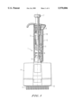
- FIG. 1 shows a 16-channel pipette in accordance with the invention
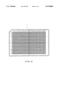
- FIG. 2 shows the sample plate used together with the illustrated pipette
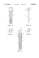
- FIG. 3 is a lateral view of the element for the set of cylinders
- FIG. 4 is a top view of the element of FIG. 3
- FIG. 5 is a lateral view of a piston suitable for the element of FIG. 3
- FIG. 6 is a top view of the piston of FIG. 5
- FIG. 7 shows the element of FIG. 3 with the pistons of FIG. 5 inserted
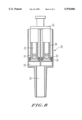
- FIG. 8 shows a second cylinder element including a piston in accordance with the invention.
- the channels may be arranged in a row or in a matrix composed of several rows. It may comprise for instance 8, 12, 16 or 24 channels.
- the pipette may also be electrically operated.
- One element comprises one or more cylinders.
- the elements may be assembled to form various sets of cylinders.
- multi-channel pipette 1 is intended for use together with plate 2 of FIG. 2, comprising 4.5 mm spaced 16 ⁇ 24 wells (NANOPLATETM, Labsystems Oy).
- the pipette has a handle 3 and a body 4 at the lower end of the handle.
- the body comprises 16 channels 5 arranged in a row, and liquid containers are fixed to the lower ends of these.
- each channel comprises a cylinder including a piston.
- the pistons are fixed to a common cross-arm, from where a piston rod 6 is directed upwards into the handle, the piston rod having at its upper end a knob 7 extending above the handle.
- the pistons are most preferably fixed to their actuator with the intermediation of a spring, whose force is greater than the friction force between the piston and the cylinder and which allows for a slight lateral movement of the pistons (cf e.g. FI patent specification 47460, corresponding to U.S. Pat. No. 3,855,868).
- the piston stroke length in the primary step, and thus the suction volume is adjustable by turning a button connected to a volume control system.
- the control system comprises a bushing 10 rotatable with regard to the piston rod but non-rotatable with regard to the handle, and the handle comprises a stopper matching the upper surface of the bushing.
- the volume control is connected with a volume display 11 based on a digital ring series (cf. e.g. FI patent specification 64752, corresponding to EP patent specification 112887).
- the pipette comprises a mechanism for removing the tip containers, including container pushers 12 and an associated spring-actuated arm 13 (cf. e.g. FR patent specification 2287941, corresponding to U.S. Pat. No. 3,991,617).
- the pusher may be actuated with a lever mechanism, thus reducing the force required for pressing.
- the plate in FIG. 2 comprises 16 horizontal rows (A-P) and 24 vertical rows (1-24).
- the outer dimensions of the plate equal the dimensions of a conventional 8 ⁇ 12 microtitration plate.
- the set of cylinders in the multi-channel pipette of FIG. 1 can be assembled from elements 14 in FIG. 3, each including two tubes 15. The elements are placed next to each other in a number corresponding to a desired even number of ducts.
- the pipette body 4 correspondingly includes appropriate means for retaining the joined elements in position. At its upper end, the element is provided with a larger common body member 16, from the bottom of which the adjoining cylinders are directed downwards. At the lower end of the cylinders, there are spaced tip members 17, into which the liquid containers are fitted.
- the mutually matching outer sides of the body members have a plane shape. The body members are dimensioned such that the distance between adjacent tubes in adjacent elements will equal the distance between the cylinders in an element.
- Piston 18 in FIG. 5 has a piston member 19 fitting into cylinders 15 and a fastening member 20 at its upper end.
- the fastening member has a vertical counter-surface 21, located laterally outside the piston member.
- the fastening member is dimensioned such that, when two, pistons are positioned with their counter-surfaces facing each other, the distance between the piston axes will equal the distance between the cylinder axes.
- Fastening member 20 may also comprise appropriate means for facilitating the positioning and joining of the pistons.
- one lateral half of counter-surface 21 is provided with a projection 22 and the other lateral half with a recess 23 matching the shape of the projection at a corresponding point.
- the projection in the one piston will engage the recess in the other piston.
- a semi-circular flange 24 is provided at the upper end of fastening member 20. When pressed against each other, the flanges form a fastening member, with which the couple of pistons is attached to the actuating arm common for the couples of pistons. In this way, the actuating arm may be identical to that of a pipette with half the number of ducts but double spacing.
- FIG. 7 shows an element 14, into which pistons 18 have been inserted.
- a common seal 25 is provided, having sliding surfaces sealed against the pistons. The seal is pressed against the bottom of the body member by a spring 26, which is fixed into position by means of a top ring 27.
- the cylinder element 28 of FIG. 8 comprises two joined circular tubes 29, each of which communicating at its lower end with the tip member 30 in the centre of the element.
- a tip container is fixed to the tip member.
- Both of the cylinders comprise a piston 31.
- Piston rods 32 are interconnected by means of a fork-like fastening means 33.
- Piston 31 has a larger lower end with a downwardly slanting circular upper surface. This surface is provided with for sealing an O-ring 34, which is pressed down by means of a support ring 35 and a spring 36. The spring is pressed from above by the bushing of fastening member 33, which has a width greater than that of the piston rod.
- the elements 28 of FIG. 8 can be assembled to form the set of cylinders of a multi-channel pipette by placing the elements next to each other with tips 30 in a row. In this way, the distance between the tips can be considerably reduced without the piston stroke required for sufficient suction volume gaining an awkward length. Still, circular cylinders provide ease of sealing.
Abstract
Description
Claims (12)
Applications Claiming Priority (2)
| Application Number | Priority Date | Filing Date | Title |
|---|---|---|---|
| FI964549 | 1996-11-13 | ||
| FI964549A FI101456B1 (en) | 1996-11-13 | 1996-11-13 | Flercylinderpipett |
Publications (1)
| Publication Number | Publication Date |
|---|---|
| US5970806A true US5970806A (en) | 1999-10-26 |
Family
ID=8547059
Family Applications (1)
| Application Number | Title | Priority Date | Filing Date |
|---|---|---|---|
| US08/966,246 Expired - Lifetime US5970806A (en) | 1996-11-13 | 1997-11-07 | Multi-cylinder pipette |
Country Status (6)
| Country | Link |
|---|---|
| US (1) | US5970806A (en) |
| JP (1) | JP4347430B2 (en) |
| DE (1) | DE19750145C2 (en) |
| FI (1) | FI101456B1 (en) |
| FR (1) | FR2755627B1 (en) |
| GB (1) | GB2319193B (en) |
Cited By (19)
| Publication number | Priority date | Publication date | Assignee | Title |
|---|---|---|---|---|
| US6244119B1 (en) * | 1999-08-03 | 2001-06-12 | Wallac Oy | Multichannel pipette system and pipette tips therefor |
| WO2001057490A1 (en) * | 2000-02-03 | 2001-08-09 | Rainin Instrument Llc. | Pipette device with tip ejector utilizing stored energy |
| EP1214977A2 (en) * | 2000-12-15 | 2002-06-19 | Wallac Oy | Pipetting method and multichannel pipetting apparatus |
| WO2002089983A1 (en) * | 2001-05-09 | 2002-11-14 | Thermo Electron Oy | Pipette with tip container |
| US20030099578A1 (en) * | 2001-10-16 | 2003-05-29 | Richard Cote | Hand-held pipettor |
| US6601433B2 (en) | 2000-06-26 | 2003-08-05 | Vistalab Technologies, Inc. | Hand-held pipette |
| US6607662B1 (en) * | 1999-09-06 | 2003-08-19 | Toyo Boseki Kabushiki Kaisha | Apparatus for purifying nucleic acids and proteins |
| US20040094638A1 (en) * | 2000-06-26 | 2004-05-20 | Cronenberg Richard A. | Automatic pipette identification |
| US20050262951A1 (en) * | 2004-05-27 | 2005-12-01 | Richard Cote | Hand held pipette |
| US20060027033A1 (en) * | 2002-10-16 | 2006-02-09 | Richard Cote | Hand-held pipette employing voice recognition control |
| US20060144169A1 (en) * | 2005-01-05 | 2006-07-06 | Amir Porat | Combinatorial pipettor device |
| US7416704B2 (en) | 2000-06-26 | 2008-08-26 | Vistalab Technologies, Inc. | Handheld pipette |
| US20090117009A1 (en) * | 2007-11-02 | 2009-05-07 | Richard Cote | Multi-channel electronic pipettor |
| USD620602S1 (en) | 2008-01-03 | 2010-07-27 | Vistalab Technologies, Inc. | Pipette |
| WO2015155317A1 (en) * | 2014-04-10 | 2015-10-15 | Gilson Sas | Multichannel pipetting system comprising two aspiration chambers that are imbricated in one another |
| USD772426S1 (en) * | 2014-01-13 | 2016-11-22 | Gilson, Inc. | Pipette system cartridge |
| US9649628B2 (en) | 2013-04-04 | 2017-05-16 | Gilson Sas | Pipetting system with improved control and volume adjustment |
| US10493444B2 (en) | 2015-10-13 | 2019-12-03 | Roche Molecular Systems, Inc. | Pipetting device for an apparatus for processing a sample or reagent, apparatus for processing a sample or reagent and method for pipetting a sample or reagent |
| US11130121B2 (en) * | 2016-06-21 | 2021-09-28 | Eppendorf Ag | Multichannel syringe for use with a metering device |
Families Citing this family (3)
| Publication number | Priority date | Publication date | Assignee | Title |
|---|---|---|---|---|
| JP5400251B2 (en) * | 2010-05-03 | 2014-01-29 | インテグラ バイオサイエンシズ コープ. | Manually oriented multi-channel electronic pipette tip positioning |
| CN102917795B (en) * | 2010-05-03 | 2014-11-12 | 因特格拉生物科学股份公司 | Manually directed, multi-channel electronic pipetting system |
| KR102396874B1 (en) * | 2021-10-15 | 2022-05-13 | 주식회사 진시스템 | Multipipette with multiple independent chambers |
Citations (11)
| Publication number | Priority date | Publication date | Assignee | Title |
|---|---|---|---|---|
| US32210A (en) * | 1861-04-30 | Rigging-clasp | ||
| US3855868A (en) * | 1972-02-10 | 1974-12-24 | O Sudvaniemi | Multiple pipette |
| US3991617A (en) * | 1974-10-15 | 1976-11-16 | Marteau D Autry Eric J H | Device for ejecting the removable tip of a pipette |
| US4215092A (en) * | 1976-04-08 | 1980-07-29 | Osmo A. Suovaniemi | Apparatus for liquid portioning and liquid transferring |
| EP0093355A1 (en) * | 1982-05-05 | 1983-11-09 | John T. Bennett, Jr. | Liquid transfer device |
| EP0112887A1 (en) * | 1982-06-29 | 1984-07-11 | Labsystems Oy | Pipette with adjustable volume. |
| EP0172508A2 (en) * | 1984-08-23 | 1986-02-26 | Labsystems Oy | Line pipette |
| EP0189900A1 (en) * | 1985-01-29 | 1986-08-06 | Fuji Photo Film Co., Ltd. | Duplex pipette |
| DE3630568A1 (en) * | 1985-09-13 | 1987-03-26 | Lars Johansson | Device for metering at least two components |
| DE3641593A1 (en) * | 1985-12-06 | 1987-06-11 | Fuji Photo Film Co Ltd | DOUBLE PIPETTE DEVICE |
| JPH08117618A (en) * | 1994-10-20 | 1996-05-14 | Sanyo Electric Co Ltd | Liquid dispensing device |
Family Cites Families (5)
| Publication number | Priority date | Publication date | Assignee | Title |
|---|---|---|---|---|
| FI46328C (en) * | 1970-05-15 | 1973-03-12 | Kone Oy | Pipette tip set especially for mechanical liquid dispensing. |
| US4260077A (en) * | 1979-10-04 | 1981-04-07 | Aelco Corporation | Dual separable dispenser |
| US4599220A (en) * | 1982-02-16 | 1986-07-08 | Yonkers Edward H | Multi-channel pipetter |
| JP2701900B2 (en) * | 1988-12-20 | 1998-01-21 | 株式会社ニチリョー | Multi pipette |
| IT225480Y1 (en) * | 1991-07-05 | 1996-11-18 | Zhermack S R L | MODULAR EQUIPMENT ESPECIALLY FOR THE DOSAGE OF MULTI-COMPONENT F LUID AND / OR PASTOUS PRODUCTS |
-
1996
- 1996-11-13 FI FI964549A patent/FI101456B1/en not_active IP Right Cessation
-
1997
- 1997-11-07 US US08/966,246 patent/US5970806A/en not_active Expired - Lifetime
- 1997-11-07 JP JP30562897A patent/JP4347430B2/en not_active Expired - Fee Related
- 1997-11-10 FR FR9714084A patent/FR2755627B1/en not_active Expired - Fee Related
- 1997-11-12 DE DE19750145A patent/DE19750145C2/en not_active Expired - Fee Related
- 1997-11-13 GB GB9724019A patent/GB2319193B/en not_active Expired - Fee Related
Patent Citations (12)
| Publication number | Priority date | Publication date | Assignee | Title |
|---|---|---|---|---|
| US32210A (en) * | 1861-04-30 | Rigging-clasp | ||
| US3855868A (en) * | 1972-02-10 | 1974-12-24 | O Sudvaniemi | Multiple pipette |
| GB1392791A (en) * | 1972-02-10 | 1975-04-30 | Suovaniemi Oa | Multiple pipette |
| US3991617A (en) * | 1974-10-15 | 1976-11-16 | Marteau D Autry Eric J H | Device for ejecting the removable tip of a pipette |
| US4215092A (en) * | 1976-04-08 | 1980-07-29 | Osmo A. Suovaniemi | Apparatus for liquid portioning and liquid transferring |
| EP0093355A1 (en) * | 1982-05-05 | 1983-11-09 | John T. Bennett, Jr. | Liquid transfer device |
| EP0112887A1 (en) * | 1982-06-29 | 1984-07-11 | Labsystems Oy | Pipette with adjustable volume. |
| EP0172508A2 (en) * | 1984-08-23 | 1986-02-26 | Labsystems Oy | Line pipette |
| EP0189900A1 (en) * | 1985-01-29 | 1986-08-06 | Fuji Photo Film Co., Ltd. | Duplex pipette |
| DE3630568A1 (en) * | 1985-09-13 | 1987-03-26 | Lars Johansson | Device for metering at least two components |
| DE3641593A1 (en) * | 1985-12-06 | 1987-06-11 | Fuji Photo Film Co Ltd | DOUBLE PIPETTE DEVICE |
| JPH08117618A (en) * | 1994-10-20 | 1996-05-14 | Sanyo Electric Co Ltd | Liquid dispensing device |
Cited By (43)
| Publication number | Priority date | Publication date | Assignee | Title |
|---|---|---|---|---|
| US6244119B1 (en) * | 1999-08-03 | 2001-06-12 | Wallac Oy | Multichannel pipette system and pipette tips therefor |
| US6607662B1 (en) * | 1999-09-06 | 2003-08-19 | Toyo Boseki Kabushiki Kaisha | Apparatus for purifying nucleic acids and proteins |
| US6986848B2 (en) * | 1999-09-06 | 2006-01-17 | Toyo Boseki Kabushiki Kaisha | Apparatus for purifying nucleic acids and proteins |
| WO2001057490A1 (en) * | 2000-02-03 | 2001-08-09 | Rainin Instrument Llc. | Pipette device with tip ejector utilizing stored energy |
| CN100360923C (en) * | 2000-02-03 | 2008-01-09 | 瑞宁器材公司 | Pipette device with tip ejector utilizing stored energy |
| US6532837B1 (en) * | 2000-02-03 | 2003-03-18 | Rainin Instrument, Llc | Pipette device with tip ejector utilizing stored energy |
| KR100712021B1 (en) | 2000-02-03 | 2007-04-27 | 레이닌 인스트루먼트 엘엘씨 | Pipette device with tip ejector utilizing stored energy |
| US8114362B2 (en) | 2000-06-26 | 2012-02-14 | Vistalab Technologies, Inc. | Automatic pipette identification |
| US20040094638A1 (en) * | 2000-06-26 | 2004-05-20 | Cronenberg Richard A. | Automatic pipette identification |
| US6749812B2 (en) | 2000-06-26 | 2004-06-15 | Vistalab Technologies | Automatic pipette detipping |
| US7416704B2 (en) | 2000-06-26 | 2008-08-26 | Vistalab Technologies, Inc. | Handheld pipette |
| US6977062B2 (en) | 2000-06-26 | 2005-12-20 | Vistalab Technologies, Inc. | Automatic pipette identification |
| US6601433B2 (en) | 2000-06-26 | 2003-08-05 | Vistalab Technologies, Inc. | Hand-held pipette |
| US20060104866A1 (en) * | 2000-06-26 | 2006-05-18 | Vistalab Technologies, Inc. | Automatic pipette identification and detipping |
| EP1214977A3 (en) * | 2000-12-15 | 2003-10-15 | Wallac Oy | Pipetting method and multichannel pipetting apparatus |
| EP1214977A2 (en) * | 2000-12-15 | 2002-06-19 | Wallac Oy | Pipetting method and multichannel pipetting apparatus |
| WO2002089983A1 (en) * | 2001-05-09 | 2002-11-14 | Thermo Electron Oy | Pipette with tip container |
| US20040208793A1 (en) * | 2001-05-09 | 2004-10-21 | Kari Jarvimaki | Pipette with tip container |
| US7682568B2 (en) * | 2001-05-09 | 2010-03-23 | Thermo Electron Oy | Pipette with tip container |
| US6923938B2 (en) | 2001-10-16 | 2005-08-02 | Matrix Technologies Corporation | Hand-held pipettor |
| US20030099578A1 (en) * | 2001-10-16 | 2003-05-29 | Richard Cote | Hand-held pipettor |
| US8088342B2 (en) | 2001-10-16 | 2012-01-03 | Matrix Technologies Corporation | Hand-held pipettor |
| US20060027033A1 (en) * | 2002-10-16 | 2006-02-09 | Richard Cote | Hand-held pipette employing voice recognition control |
| US7284454B2 (en) | 2004-05-27 | 2007-10-23 | Matrix Technologies Corporation | Hand held pipette |
| US20050262951A1 (en) * | 2004-05-27 | 2005-12-01 | Richard Cote | Hand held pipette |
| US7219567B2 (en) | 2005-01-05 | 2007-05-22 | Bio-Magnetics Ltd. | Combinatorial pipettor device |
| US20060144169A1 (en) * | 2005-01-05 | 2006-07-06 | Amir Porat | Combinatorial pipettor device |
| US20090117009A1 (en) * | 2007-11-02 | 2009-05-07 | Richard Cote | Multi-channel electronic pipettor |
| USD620602S1 (en) | 2008-01-03 | 2010-07-27 | Vistalab Technologies, Inc. | Pipette |
| US9649628B2 (en) | 2013-04-04 | 2017-05-16 | Gilson Sas | Pipetting system with improved control and volume adjustment |
| USD807525S1 (en) | 2014-01-13 | 2018-01-09 | Gilson, Inc. | Pipette |
| USD998818S1 (en) | 2014-01-13 | 2023-09-12 | Gilson, Inc. | Cartridge for a pipette device |
| USD998169S1 (en) | 2014-01-13 | 2023-09-05 | Gilson, Inc. | Pipette |
| USD772426S1 (en) * | 2014-01-13 | 2016-11-22 | Gilson, Inc. | Pipette system cartridge |
| USD969340S1 (en) | 2014-01-13 | 2022-11-08 | Gilson, Inc. | Pipette |
| FR3019895A1 (en) * | 2014-04-10 | 2015-10-16 | Gilson Sas | MULTICHANNEL PIPETTING SYSTEM COMPRISING TWO NARROW SUCTION CHAMBERS ONE IN THE OTHER |
| CN106132547B (en) * | 2014-04-10 | 2020-02-07 | 吉尔松有限合伙公司 | Multichannel pipetting system comprising two suction chambers imbricated one above the other |
| US10639624B2 (en) * | 2014-04-10 | 2020-05-05 | Gilson Sas | Multichannel pipetting system comprising two aspiration chambers that are imbricated in one another |
| US20170028397A1 (en) * | 2014-04-10 | 2017-02-02 | Gilson Sas | Multichannel pipetting system comprising two aspiration chambers that are imbricated in one another |
| CN106132547A (en) * | 2014-04-10 | 2016-11-16 | 吉尔松有限合伙公司 | Comprise two each other in the multichannel liquor-transferring system of imbricated suction room |
| WO2015155317A1 (en) * | 2014-04-10 | 2015-10-15 | Gilson Sas | Multichannel pipetting system comprising two aspiration chambers that are imbricated in one another |
| US10493444B2 (en) | 2015-10-13 | 2019-12-03 | Roche Molecular Systems, Inc. | Pipetting device for an apparatus for processing a sample or reagent, apparatus for processing a sample or reagent and method for pipetting a sample or reagent |
| US11130121B2 (en) * | 2016-06-21 | 2021-09-28 | Eppendorf Ag | Multichannel syringe for use with a metering device |
Also Published As
| Publication number | Publication date |
|---|---|
| JPH10156196A (en) | 1998-06-16 |
| GB9724019D0 (en) | 1998-01-14 |
| JP4347430B2 (en) | 2009-10-21 |
| FI964549A (en) | 1998-05-14 |
| FI101456B (en) | 1998-06-30 |
| GB2319193A (en) | 1998-05-20 |
| FR2755627B1 (en) | 2004-06-11 |
| DE19750145A1 (en) | 1998-05-14 |
| FI964549A0 (en) | 1996-11-13 |
| FI101456B1 (en) | 1998-06-30 |
| DE19750145C2 (en) | 2000-05-18 |
| GB2319193B (en) | 2001-04-18 |
| FR2755627A1 (en) | 1998-05-15 |
Similar Documents
| Publication | Publication Date | Title |
|---|---|---|
| US5970806A (en) | Multi-cylinder pipette | |
| EP1074302B1 (en) | Multichannel pipette system and pipette tips therefor | |
| US6841130B2 (en) | Pipetting method and multichannel pipetting apparatus | |
| US5580529A (en) | Aerosol and liquid transfer resistant pipette tip apparatus | |
| US5983733A (en) | Manual pipette | |
| US4498510A (en) | Device for drawing, holding and dispensing liquid | |
| EP1123254A1 (en) | Position triggered dispenser and methods | |
| GB1563959A (en) | Method and apparatus fo liquid portioning liquid transferring and for diluting series | |
| US5540889A (en) | Apparatus and method for a highly parallel pipetter | |
| AU662216B2 (en) | Tip part pipette | |
| US20050220676A1 (en) | Multi-range pipette | |
| WO1997034138A1 (en) | Method of and apparatus for transferring micro quantities of liquid samples to discrete locations | |
| US8117927B2 (en) | Pipette providing sampling via back-and-forth movement of the piston | |
| US5817955A (en) | Apparatus for simultaneous aspiration and dispensation of fluids | |
| FI58875B (en) | pipette | |
| US20030223910A1 (en) | Pipettor systems and components | |
| US7438862B2 (en) | Apparatus for simultaneous processing of multiple samples | |
| GB2045641A (en) | Pipette | |
| US4675163A (en) | Laboratory device | |
| US20040141885A1 (en) | Pipettor systems and components | |
| US20080260592A1 (en) | Discretely Adjustable Pipettor | |
| EP0172508B1 (en) | Line pipette | |
| JP4965572B2 (en) | Liquid dispensing device with cap and diaphragm | |
| US4649967A (en) | Multiple efflux apparatuses for transferring fluid | |
| US4602517A (en) | Fluid sampling method and apparatus |
Legal Events
| Date | Code | Title | Description |
|---|---|---|---|
| AS | Assignment |
Owner name: LABSYSTEMS OY, FINLAND Free format text: ASSIGNMENT OF ASSIGNOR'S INTEREST. RE-RECORD TO CORRECT THE RECORDATION DATE OF MAY 11, 1998 TO MAY 08, 1998 PREVIOUSLY RECORDED AT REEL 9166 FRAME 0106.;ASSIGNORS:TELIMAA, JUHA;HEINONEN, MAUNO;JARVIMAKI, KARI;AND OTHERS;REEL/FRAME:009359/0584;SIGNING DATES FROM 19971017 TO 19971020 |
|
| AS | Assignment |
Owner name: LABSYSTEMS OY, FINLAND Free format text: ;ASSIGNORS:TELIMAA, JUHA;HEINONEN, MAUNO;JARVIMAKI, KARI;AND OTHERS;REEL/FRAME:009166/0106;SIGNING DATES FROM 19971017 TO 19971020 |
|
| STCF | Information on status: patent grant |
Free format text: PATENTED CASE |
|
| CC | Certificate of correction | ||
| FPAY | Fee payment |
Year of fee payment: 4 |
|
| REMI | Maintenance fee reminder mailed | ||
| FPAY | Fee payment |
Year of fee payment: 8 |
|
| FPAY | Fee payment |
Year of fee payment: 12 |