US5971251A - Method of welding a terminal to a flat flexible cable - Google Patents
Method of welding a terminal to a flat flexible cable Download PDFInfo
- Publication number
- US5971251A US5971251A US08/958,110 US95811097A US5971251A US 5971251 A US5971251 A US 5971251A US 95811097 A US95811097 A US 95811097A US 5971251 A US5971251 A US 5971251A
- Authority
- US
- United States
- Prior art keywords
- wire
- insulating coating
- tooling head
- tab
- top surface
- Prior art date
- Legal status (The legal status is an assumption and is not a legal conclusion. Google has not performed a legal analysis and makes no representation as to the accuracy of the status listed.)
- Expired - Fee Related
Links
Images
Classifications
-
- H—ELECTRICITY
- H05—ELECTRIC TECHNIQUES NOT OTHERWISE PROVIDED FOR
- H05K—PRINTED CIRCUITS; CASINGS OR CONSTRUCTIONAL DETAILS OF ELECTRIC APPARATUS; MANUFACTURE OF ASSEMBLAGES OF ELECTRICAL COMPONENTS
- H05K3/00—Apparatus or processes for manufacturing printed circuits
- H05K3/30—Assembling printed circuits with electric components, e.g. with resistor
- H05K3/32—Assembling printed circuits with electric components, e.g. with resistor electrically connecting electric components or wires to printed circuits
- H05K3/328—Assembling printed circuits with electric components, e.g. with resistor electrically connecting electric components or wires to printed circuits by welding
-
- H—ELECTRICITY
- H01—ELECTRIC ELEMENTS
- H01R—ELECTRICALLY-CONDUCTIVE CONNECTIONS; STRUCTURAL ASSOCIATIONS OF A PLURALITY OF MUTUALLY-INSULATED ELECTRICAL CONNECTING ELEMENTS; COUPLING DEVICES; CURRENT COLLECTORS
- H01R4/00—Electrically-conductive connections between two or more conductive members in direct contact, i.e. touching one another; Means for effecting or maintaining such contact; Electrically-conductive connections having two or more spaced connecting locations for conductors and using contact members penetrating insulation
- H01R4/02—Soldered or welded connections
- H01R4/023—Soldered or welded connections between cables or wires and terminals
-
- H—ELECTRICITY
- H01—ELECTRIC ELEMENTS
- H01R—ELECTRICALLY-CONDUCTIVE CONNECTIONS; STRUCTURAL ASSOCIATIONS OF A PLURALITY OF MUTUALLY-INSULATED ELECTRICAL CONNECTING ELEMENTS; COUPLING DEVICES; CURRENT COLLECTORS
- H01R43/00—Apparatus or processes specially adapted for manufacturing, assembling, maintaining, or repairing of line connectors or current collectors or for joining electric conductors
- H01R43/02—Apparatus or processes specially adapted for manufacturing, assembling, maintaining, or repairing of line connectors or current collectors or for joining electric conductors for soldered or welded connections
- H01R43/0228—Apparatus or processes specially adapted for manufacturing, assembling, maintaining, or repairing of line connectors or current collectors or for joining electric conductors for soldered or welded connections without preliminary removing of insulation before soldering or welding
-
- H—ELECTRICITY
- H01—ELECTRIC ELEMENTS
- H01L—SEMICONDUCTOR DEVICES NOT COVERED BY CLASS H10
- H01L2924/00—Indexing scheme for arrangements or methods for connecting or disconnecting semiconductor or solid-state bodies as covered by H01L24/00
- H01L2924/0001—Technical content checked by a classifier
- H01L2924/0002—Not covered by any one of groups H01L24/00, H01L24/00 and H01L2224/00
-
- H—ELECTRICITY
- H01—ELECTRIC ELEMENTS
- H01R—ELECTRICALLY-CONDUCTIVE CONNECTIONS; STRUCTURAL ASSOCIATIONS OF A PLURALITY OF MUTUALLY-INSULATED ELECTRICAL CONNECTING ELEMENTS; COUPLING DEVICES; CURRENT COLLECTORS
- H01R12/00—Structural associations of a plurality of mutually-insulated electrical connecting elements, specially adapted for printed circuits, e.g. printed circuit boards [PCB], flat or ribbon cables, or like generally planar structures, e.g. terminal strips, terminal blocks; Coupling devices specially adapted for printed circuits, flat or ribbon cables, or like generally planar structures; Terminals specially adapted for contact with, or insertion into, printed circuits, flat or ribbon cables, or like generally planar structures
- H01R12/50—Fixed connections
- H01R12/59—Fixed connections for flexible printed circuits, flat or ribbon cables or like structures
Definitions
- This invention generally relates to a unique method of welding a terminal to a wire in a flat flexible cable.
- Flat flexible cables are used in wiring harnesses for vehicles. They are usually used in areas of the vehicle were packaging constraints require small, thin and flexible wiring harness assemblies to extend between electrical connectors.
- a typical flat flexible cable is comprised of a plurality of small gauge wires spaced apart from one another and surrounded by an insulating material. These flexible cables can be of various lengths depending on the application.
- conductive terminals In order for the flat flexible cable to be electrically connected to a connector, conductive terminals have to be connected to each wire at an end of the cable. Because the wires in the flexible cable are very small gauge, the connecting methods used have to remove enough insulating material to provide sufficient surface area along the wire so that it can be securely connected to the terminal. A good connection between the wire and the terminal is required for good reliability, strength, and electrical properties.
- connection methods involve crimping or welding the terminal to the wire. Welding is preferred over crimping because the welding method provides greater surface area along the wire, thus, providing better reliability, strength and electrical properties.
- the wires at the ends of the flat flexible cable must be stripped of their insulating coating. Currently, this stripping operation involves either an abrasion process or a laser process. Once the insulating coating has been stripped away, standard ultrasonic tooling can be used to weld the terminal to the exposed wire.
- this invention provides a method of welding terminals to wires in a flat flexible cable for use in vehicle wiring harnesses.
- the flat flexible cable includes a plurality of wires spaced apart from one another and surrounded by an insulating coating.
- a terminal with a tab is welded to each wire in the flat flexible cable.
- the inventive welding method includes placing the tab portion of the terminal underneath one of the wires in the flat flexible cable.
- a tooling base supports the tab and the flat flexible cable.
- a tooling head engages the insulating coating along the top surface of the wire and moves in a path along the wire. The heat resulting from the friction between the tooling head and the insulating coating causes the insulating coating to flow away from the tooling head exposing the wire and frictionally welding the bottom surface of the wire to the top surface of the tab.
- the method of the invention comprises the steps of providing a wire defining a longitudinal axis having a top and a bottom surface each covered by an insulating coating.
- a conductive terminal having a top and a bottom surface has a tab supported on a tooling base with the bottom surface of the coated wire placed over the tab.
- the top surface of the coated wire is engaged with a tooling head, and the tooling head is moved against the insulating coating sufficiently for heat to result from the frictional engagement between the tooling head and the insulating coating.
- the heat causes the insulating coating to flow away from the tooling head to expose the wire and to frictionally weld the wire to the top surface of the tab.
- the welding techniques, speed, etc. are generally known in the art as ultrasonic welding.
- the tooling head has a plurality of ridges to facilitate the welding.
- the tab may be provided with structure that provides space to receive the flowing insulation during the weld process.
- the advantages of the invention include eliminating the abrasive or laser stripping processes for removing the insulating coating from the wires while providing an inexpensive and efficient way to remove the insulating coating during the welding process which does not break or damage the wires.
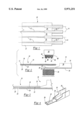
- FIG. 1 is shows a flat flexible cable with terminals
- FIG. 2 is a cross sectional, exploded view of a flat flexible cable, a terminal and the tooling used in the inventive welding method;
- FIG. 3 is a cross sectional view of a terminal welded to a wire in a flat flexible cable
- FIG. 4 shows a terminal with a conductive projection.
- a flat flexible cable with welded terminals is shown generally at 10 in FIG. 1.
- the flat flexible cable is comprised of a plurality of wires 12 spaced apart from one another, each defining a longitudinal axis 14.
- a conductive terminal 16 is welded to each wire 12. The terminals 16 are used to electrically connect the flat flexible cable 10 to an electrical connector (not shown) in a vehicle wiring harness assembly.
- Each wire 12 has a top surface 18 and a bottom surface 20, as shown in FIG. 2.
- An insulating coating 22 extends between and surrounds the wires 12. As shown, portions 23 of insulation remain between terminals 16.
- the conductive terminal 16 includes a connector 24 and a flat tab 26 extending outwardly from the connector 24.
- the tab 26 has a top surface 32 and a bottom surface 34.
- the top surface 32 of the tab 26 is welded to the bottom surface 20 of the wire 12 such that the conductive terminal 16 extends outwardly from the wire 12 along its longitudinal axis 14.
- a tooling base 36 supports the bottom surface 34 of the tab 26.
- the base and support structure may be as known in the art.
- the flat flexible cable 10 is placed on top of the tab 26 such that a wire 12 in the cable 10 is directly over the tab 26.
- a tooling head 38 engages the insulating coating 22 along the top surface 18 of the wire 12.
- the terminal 16 and the flat flexible cable 10 are held fixed with respect to the tooling head 38.
- the tooling head 38 is moved against the insulating coating 22 above the wire 12 such that the heat resulting from this frictional engagement between the tooling head 38 and the insulating coating 22 causes the insulating coating 22 to flow away from the tooling head 38, exposes the wire 12 and frictionally welds the wire 12 to the top surface 32 of the tab 26.
- This process is known as ultrasonic welding. As known, during this process there is a force applied between holding tooling head 38 against base 36. Thus, the welding process includes removing the insulating coating 22 from the wire 12 and welding the wire 12 to the terminal 16 simultaneously. This results in the elimination of a separate process for stripping or removing the insulating coating 22 before welding.
- the tooling head 38 has a flattened tip 40 having a width, extending into the plane of FIG. 2, which is less than or equal to the diameter of the wire 12.
- the tooling head 38 engages the insulating coating 22 directly over the top surface 18 of the wire 12.
- the tooling head 38 is then moved along the length of the wire 12 in a path parallel to the longitudinal axis 14 of the wire 12 such that the insulating coating 22 is only removed directly over the top surface 18 of the wire 12.
- the tooling head 38 has at least one triangular ridge 42 (three (3) ridges 42 are shown in FIG. 2) extending perpendicularly to the longitudinal axis 14 of the coated wire 12.
- the length of the ridge 42 is preferably less than or equal to the diameter of the wire 12.
- Each ridge 42 has a flat base 44 supported by the tooling head 38 with a first side 46 and a second side 48 extending downwardly at an angle from the flat base 44 to a pointed tip 50.
- the lengths of the ridges 42 are perpendicular to the longitudinal axes 14 of the wires, such that each pointed tip 50 is spaced apart from one another and will contact the insulating coating 22 at a different location along the top surface 18 of the wire 12. Placing the lengths of the ridges 42 perpendicular to the wires 12 prevents the wires 12 from being damaged or broken during the welding process when the tooling head 38 is moved back and forth along the wire 12.
- the tooling head 38 In the welding process the tooling head 38 is moved very quickly along a path parallel to the longitudinal axis 14. The tips 50 engage the insulating coating 22 directly over the wire 22 causing the insulating coating 22 to melt and flow away from the tooling head 38 along the top 18 and bottom 20 surfaces of the wire 12 due to the heat created by the frictional engagement between the tooling head 38 and the wire 12. When the wire 12 is exposed to the tab 26 the friction welds them securely together.
- the terminal 16 is securely welded to the flat flexible cable 10, as shown in FIG. 3.
- a portion of the top surface 18 of the wire 12 is exposed where the insulating coating 22 has been removed, while the bottom surface 20 of the wire 12 is welded to the top surface 32 of the tab 26.
- the insulating portions 23 remain between wires 12.
- the tooling head 38 is moved against the insulating coating 22 along the top surface 18 of the wire 12
- the insulating coating 22 along the bottom surface 20 of the wire 12 flows away from the wire 12 due to the heat created from the frictional engagement between the tooling head 38 and the cable 10. This allows the tab 26 to securely bond to the wire 12 providing good reliability, strength, and electrical properties.
- the connector 24 portion of the terminal 16 is U-shaped with a flat bottom 28 and two upwardly extending sides 30. Sides 30 are rolled to form a terminal pin.
- the tab 26 extends outwardly from the bottom 28 of the connector 24 and is placed directly under the wire 12 in the flat flexible cable 10. While a U-shaped connector 24 is shown, the connector 24 can be of various shapes known in the art, such as a box, pin, etc..
- the top surface of the tab 26 includes at least one conductive projection 52 extending upwardly from the flat surface of the tab 26.
- the conductive projection 52 is placed directly underneath the bottom surface 32 of the wire 12.
- the addition of a conductive projection 52 provides a space for allowing the insulating material 22 to flow away from the bottom surface 20 of the wire when the tooling head 38 is frictionally engaging the flat flexible cable 10. This allows greater surface area along the bottom surface 20 of the wire 12 to be exposed which increases the strength of the weld.
- only one conductive projection 52 is shown in another embodiment, two conductive projections 52 are used on a tab 26.
- the flat flexible cable 10 is comprised of copper wires 12 surrounded by a polyester insulating coating 22.
- a copper terminal 16 is welded to each copper wire 12 in the cable 10 during the welding process.
- the tooling used for this welding process is standard ultrasonic tooling well known in the art.
- One tooling head 38 is used to weld each terminal 16 to each wire, thus either a single tooling head 38 is used to weld each terminal 16 to its respective wire 12, moving from one wire 12 to the next, or a plurality of tooling heads 38 are used to simultaneously weld all of the terminals 16 to all of the wires in the cable 10.
- the preferred method of welding a terminal 16 to a wire 12 includes the following steps: providing a wire 12 defining a longitudinal axis 14 having a top surface 18 and a bottom surface 20 each covered by an insulating coating 22; providing a conductive terminal 16 having a tab 26 with a top surface 32 and a bottom surface 34; supporting the bottom surface 32 of the tab 26 on a tooling base 36 with the bottom surface 20 of the coated wire 12 thereover; engaging the top surface 18 of the coated wire 12 with a tooling head 38; and moving the tooling head 38 against the insulating coating 22 sufficiently for the heat resulting from the frictional engagement between the tooling head 38 and the insulating coating 22 to cause the insulating coating 22 to flow away from the tooling head 38, expose the wire 12 and frictionally weld the wire 12 to the top surface 32 of the tab 26.
Abstract
Description
Claims (4)
Priority Applications (1)
| Application Number | Priority Date | Filing Date | Title |
|---|---|---|---|
| US08/958,110 US5971251A (en) | 1997-10-27 | 1997-10-27 | Method of welding a terminal to a flat flexible cable |
Applications Claiming Priority (1)
| Application Number | Priority Date | Filing Date | Title |
|---|---|---|---|
| US08/958,110 US5971251A (en) | 1997-10-27 | 1997-10-27 | Method of welding a terminal to a flat flexible cable |
Publications (1)
| Publication Number | Publication Date |
|---|---|
| US5971251A true US5971251A (en) | 1999-10-26 |
Family
ID=25500605
Family Applications (1)
| Application Number | Title | Priority Date | Filing Date |
|---|---|---|---|
| US08/958,110 Expired - Fee Related US5971251A (en) | 1997-10-27 | 1997-10-27 | Method of welding a terminal to a flat flexible cable |
Country Status (1)
| Country | Link |
|---|---|
| US (1) | US5971251A (en) |
Cited By (13)
| Publication number | Priority date | Publication date | Assignee | Title |
|---|---|---|---|---|
| US20040038598A1 (en) * | 2001-01-12 | 2004-02-26 | Ernst Steiner | Method and device for connecting conductors |
| US20050258153A1 (en) * | 2004-05-20 | 2005-11-24 | Visteon Global Technologies, Inc. | System and method for joining flat flexible cables |
| US7275675B1 (en) | 2004-08-20 | 2007-10-02 | United States Of America As Represented By The Administrator Of The National Aeronautics And Space Administration | Friction stir weld tools |
| US8011557B1 (en) * | 2010-08-04 | 2011-09-06 | Cheng Uei Precision Industry Co., Ltd. | Automatic soldering machine |
| EP1923956A3 (en) * | 2006-11-15 | 2011-10-05 | Hitachi, Ltd. | Connection structure of terminal, method of connecting terminal, and control device |
| US20130042960A1 (en) * | 2010-04-30 | 2013-02-21 | Orthodyne Electronics Corporation | Ultrasonic bonding systems and methods of using the same |
| US20130294757A1 (en) * | 2010-11-18 | 2013-11-07 | Voss Automotive Gmbh | Prefabricated electrically heatable media line and method for producing a media line of this kind |
| US20150364837A1 (en) * | 2013-02-22 | 2015-12-17 | Furukawa Electric Co., Ltd. | Method for Manufacturing Crimp Terminal, Crimp Terminal, and Wire Harness |
| US20160035463A1 (en) * | 2014-07-30 | 2016-02-04 | Yazaki Corporation | Method for bonding flat cable and bonding object, ultrasonic bonding device, and cable |
| US20190084078A1 (en) * | 2016-03-18 | 2019-03-21 | Honda Motor Co., Ltd. | Ultrasonic welding device and ultrasonic welding method |
| US20190131752A1 (en) * | 2016-03-18 | 2019-05-02 | Honda Motor Co., Ltd. | Ultrasonic welding device and ultrasonic welding method |
| US20200059056A1 (en) * | 2018-08-14 | 2020-02-20 | Te Connectivity Germany Gmbh | Method Of Attaching A Contact Element To A Conductive Path A Conductor Plate |
| US11387162B2 (en) * | 2012-01-05 | 2022-07-12 | Littelfuse, Inc. | Discrete power transistor package having solderless DBC to leadframe attach |
Citations (5)
| Publication number | Priority date | Publication date | Assignee | Title |
|---|---|---|---|---|
| JPS5364788A (en) * | 1976-11-19 | 1978-06-09 | Seiko Instr & Electronics Ltd | Jointing method of wire |
| JPS6153738A (en) * | 1984-08-24 | 1986-03-17 | Hitachi Micro Comput Eng Ltd | Semiconductor device |
| GB2177336A (en) * | 1985-06-19 | 1987-01-21 | Luc Technologies Ltd | Improvement in electrical connections |
| US4668581A (en) * | 1984-01-25 | 1987-05-26 | Luc Technologies Limited | Bonding electrical conductors and bonded products |
| EP0286031A2 (en) * | 1987-04-03 | 1988-10-12 | Hitachi, Ltd. | Ultrasonic wire bonding method |
-
1997
- 1997-10-27 US US08/958,110 patent/US5971251A/en not_active Expired - Fee Related
Patent Citations (5)
| Publication number | Priority date | Publication date | Assignee | Title |
|---|---|---|---|---|
| JPS5364788A (en) * | 1976-11-19 | 1978-06-09 | Seiko Instr & Electronics Ltd | Jointing method of wire |
| US4668581A (en) * | 1984-01-25 | 1987-05-26 | Luc Technologies Limited | Bonding electrical conductors and bonded products |
| JPS6153738A (en) * | 1984-08-24 | 1986-03-17 | Hitachi Micro Comput Eng Ltd | Semiconductor device |
| GB2177336A (en) * | 1985-06-19 | 1987-01-21 | Luc Technologies Ltd | Improvement in electrical connections |
| EP0286031A2 (en) * | 1987-04-03 | 1988-10-12 | Hitachi, Ltd. | Ultrasonic wire bonding method |
Cited By (21)
| Publication number | Priority date | Publication date | Assignee | Title |
|---|---|---|---|---|
| US20040038598A1 (en) * | 2001-01-12 | 2004-02-26 | Ernst Steiner | Method and device for connecting conductors |
| US7124504B2 (en) * | 2001-01-12 | 2006-10-24 | Schunk Ultraschalltechnik Gmbh | Method and device for connecting conductors |
| US20050258153A1 (en) * | 2004-05-20 | 2005-11-24 | Visteon Global Technologies, Inc. | System and method for joining flat flexible cables |
| US7009142B2 (en) * | 2004-05-20 | 2006-03-07 | Visteon Global Technologies Inc. | System and method for joining flat flexible cables |
| US7275675B1 (en) | 2004-08-20 | 2007-10-02 | United States Of America As Represented By The Administrator Of The National Aeronautics And Space Administration | Friction stir weld tools |
| EP1923956A3 (en) * | 2006-11-15 | 2011-10-05 | Hitachi, Ltd. | Connection structure of terminal, method of connecting terminal, and control device |
| US20130042960A1 (en) * | 2010-04-30 | 2013-02-21 | Orthodyne Electronics Corporation | Ultrasonic bonding systems and methods of using the same |
| US8544717B2 (en) * | 2010-04-30 | 2013-10-01 | Orthodyne Electronics Corporation | Ultrasonic bonding systems and methods of using the same |
| US8573468B1 (en) | 2010-04-30 | 2013-11-05 | Orthodyne Electronics Corporation | Ultrasonic bonding systems and methods of using the same |
| US8011557B1 (en) * | 2010-08-04 | 2011-09-06 | Cheng Uei Precision Industry Co., Ltd. | Automatic soldering machine |
| US20130294757A1 (en) * | 2010-11-18 | 2013-11-07 | Voss Automotive Gmbh | Prefabricated electrically heatable media line and method for producing a media line of this kind |
| US9644776B2 (en) * | 2010-11-18 | 2017-05-09 | Voss Automotive Gmbh | Prefabricated electrically heatable media line and method for producing a media line of this kind |
| US11387162B2 (en) * | 2012-01-05 | 2022-07-12 | Littelfuse, Inc. | Discrete power transistor package having solderless DBC to leadframe attach |
| US20150364837A1 (en) * | 2013-02-22 | 2015-12-17 | Furukawa Electric Co., Ltd. | Method for Manufacturing Crimp Terminal, Crimp Terminal, and Wire Harness |
| US9564691B2 (en) * | 2013-02-22 | 2017-02-07 | Furukawa Automotive Systems Inc. | Method for manufacturing crimp terminal, crimp terminal, and wire harness |
| US20160035463A1 (en) * | 2014-07-30 | 2016-02-04 | Yazaki Corporation | Method for bonding flat cable and bonding object, ultrasonic bonding device, and cable |
| US9607739B2 (en) * | 2014-07-30 | 2017-03-28 | Yazaki Corporation | Method for bonding flat cable and bonding object, ultrasonic bonding device, and cable |
| US20190084078A1 (en) * | 2016-03-18 | 2019-03-21 | Honda Motor Co., Ltd. | Ultrasonic welding device and ultrasonic welding method |
| US20190131752A1 (en) * | 2016-03-18 | 2019-05-02 | Honda Motor Co., Ltd. | Ultrasonic welding device and ultrasonic welding method |
| US20200059056A1 (en) * | 2018-08-14 | 2020-02-20 | Te Connectivity Germany Gmbh | Method Of Attaching A Contact Element To A Conductive Path A Conductor Plate |
| US11888279B2 (en) * | 2018-08-14 | 2024-01-30 | Te Connectivity Germany Gmbh | Method of attaching a contact element to a conductive path a conductor plate |
Similar Documents
| Publication | Publication Date | Title |
|---|---|---|
| US5971251A (en) | Method of welding a terminal to a flat flexible cable | |
| US4966565A (en) | Crimp-style terminal and method of connecting crimp-style terminal and electric cable together | |
| US6793543B2 (en) | Bus bar structure | |
| EP0650226B1 (en) | A molded circuit component unit for connecting lead wires and a method of manufacturing same | |
| EP0703117B1 (en) | Electric connection casing | |
| EP0337400B1 (en) | Apparatus for connecting sets of electric wires to lead wires | |
| EP0675567B1 (en) | Wire harness and method of manufacturing the same | |
| CN104094472A (en) | Crimp terminal, connection structure, connector, and crimp connection method for crimp terminal | |
| EP0261905B1 (en) | An electrical connector and a method for connecting wires thereto | |
| US3243757A (en) | Electrical connections | |
| US5829129A (en) | Wiring harness and method of producing the same | |
| US5824955A (en) | Connecting structure between flat cable and terminals | |
| EP0312550A1 (en) | Insulation displacement terminal. | |
| JP2008011677A (en) | Electric connection box | |
| JP2001068244A (en) | Current-carrying welding method of cable conductor and its connector | |
| JP2004273333A (en) | Flat cable | |
| JPH088034A (en) | Connector assembly method for flat cable | |
| JPH087968A (en) | Connector and its assembling method | |
| US6527161B2 (en) | Method of connecting electric wires | |
| US5211578A (en) | Connector housing assembly for discrete wires | |
| JPH10149843A (en) | Welding terminal | |
| EP3916920B1 (en) | Terminal connecting structure | |
| JP3039150B2 (en) | Terminal treatment structure of insulation displacement connector | |
| JP2825492B2 (en) | Soldering structure of outer conductor of coaxial cable and method therefor | |
| JPH01241780A (en) | Shielded cable end treating apparatus |
Legal Events
| Date | Code | Title | Description |
|---|---|---|---|
| AS | Assignment |
Owner name: UNITED TECHNOLOGIES AUTOMATIVE, INC., MICHIGAN Free format text: ASSIGNMENT OF ASSIGNORS INTEREST;ASSIGNORS:MOORE, NATHAN;WAYT, ROGER;REEL/FRAME:008802/0708 Effective date: 19971016 |
|
| AS | Assignment |
Owner name: UT AUTOMOTIVE DEARBORN, INC., MICHIGAN Free format text: ASSIGNMENT OF ASSIGNORS INTEREST;ASSIGNOR:UNITED TECHNOLOGIES AUTOMOTIVE, INC.;REEL/FRAME:009083/0924 Effective date: 19980330 |
|
| AS | Assignment |
Owner name: LEAR AUTOMOTIVE DEARBORN, INC., MICHIGAN Free format text: CHANGE OF NAME;ASSIGNOR:UT AUTOMOTIVE DEARBORN, INC.;REEL/FRAME:010061/0393 Effective date: 19990528 |
|
| FEPP | Fee payment procedure |
Free format text: PAYOR NUMBER ASSIGNED (ORIGINAL EVENT CODE: ASPN); ENTITY STATUS OF PATENT OWNER: LARGE ENTITY |
|
| FPAY | Fee payment |
Year of fee payment: 4 |
|
| AS | Assignment |
Owner name: JPMORGAN CHASE BANK, N.A., AS GENERAL ADMINISTRATI Free format text: SECURITY AGREEMENT;ASSIGNOR:LEAR AUTOMOTIVE DEARBORN, INC.;REEL/FRAME:017823/0950 Effective date: 20060425 |
|
| REMI | Maintenance fee reminder mailed | ||
| LAPS | Lapse for failure to pay maintenance fees | ||
| STCH | Information on status: patent discontinuation |
Free format text: PATENT EXPIRED DUE TO NONPAYMENT OF MAINTENANCE FEES UNDER 37 CFR 1.362 |
|
| FP | Lapsed due to failure to pay maintenance fee |
Effective date: 20071026 |
|
| AS | Assignment |
Owner name: LEAR AUTOMOTIVE DEARBORN, INC., MICHIGAN Free format text: RELEASE BY SECURED PARTY;ASSIGNOR:JPMORGAN CHASE BANK, N.A.;REEL/FRAME:032712/0428 Effective date: 20100830 |