US5973622A - Keyboard with a two-dimensional actuator for generating direction signals - Google Patents
Keyboard with a two-dimensional actuator for generating direction signals Download PDFInfo
- Publication number
- US5973622A US5973622A US08/928,912 US92891297A US5973622A US 5973622 A US5973622 A US 5973622A US 92891297 A US92891297 A US 92891297A US 5973622 A US5973622 A US 5973622A
- Authority
- US
- United States
- Prior art keywords
- actuator
- encoding circuit
- page
- keyboard
- keys
- Prior art date
- Legal status (The legal status is an assumption and is not a legal conclusion. Google has not performed a legal analysis and makes no representation as to the accuracy of the status listed.)
- Expired - Lifetime
Links
Images

Classifications
-
- G—PHYSICS
- G06—COMPUTING; CALCULATING OR COUNTING
- G06F—ELECTRIC DIGITAL DATA PROCESSING
- G06F3/00—Input arrangements for transferring data to be processed into a form capable of being handled by the computer; Output arrangements for transferring data from processing unit to output unit, e.g. interface arrangements
- G06F3/01—Input arrangements or combined input and output arrangements for interaction between user and computer
- G06F3/048—Interaction techniques based on graphical user interfaces [GUI]
- G06F3/0487—Interaction techniques based on graphical user interfaces [GUI] using specific features provided by the input device, e.g. functions controlled by the rotation of a mouse with dual sensing arrangements, or of the nature of the input device, e.g. tap gestures based on pressure sensed by a digitiser
- G06F3/0489—Interaction techniques based on graphical user interfaces [GUI] using specific features provided by the input device, e.g. functions controlled by the rotation of a mouse with dual sensing arrangements, or of the nature of the input device, e.g. tap gestures based on pressure sensed by a digitiser using dedicated keyboard keys or combinations thereof
- G06F3/04892—Arrangements for controlling cursor position based on codes indicative of cursor displacements from one discrete location to another, e.g. using cursor control keys associated to different directions or using the tab key
-
- G—PHYSICS
- G06—COMPUTING; CALCULATING OR COUNTING
- G06F—ELECTRIC DIGITAL DATA PROCESSING
- G06F3/00—Input arrangements for transferring data to be processed into a form capable of being handled by the computer; Output arrangements for transferring data from processing unit to output unit, e.g. interface arrangements
- G06F3/01—Input arrangements or combined input and output arrangements for interaction between user and computer
- G06F3/02—Input arrangements using manually operated switches, e.g. using keyboards or dials
- G06F3/0202—Constructional details or processes of manufacture of the input device
- G06F3/021—Arrangements integrating additional peripherals in a keyboard, e.g. card or barcode reader, optical scanner
- G06F3/0213—Arrangements providing an integrated pointing device in a keyboard, e.g. trackball, mini-joystick
-
- G—PHYSICS
- G06—COMPUTING; CALCULATING OR COUNTING
- G06F—ELECTRIC DIGITAL DATA PROCESSING
- G06F3/00—Input arrangements for transferring data to be processed into a form capable of being handled by the computer; Output arrangements for transferring data from processing unit to output unit, e.g. interface arrangements
- G06F3/01—Input arrangements or combined input and output arrangements for interaction between user and computer
- G06F3/03—Arrangements for converting the position or the displacement of a member into a coded form
- G06F3/033—Pointing devices displaced or positioned by the user, e.g. mice, trackballs, pens or joysticks; Accessories therefor
- G06F3/0354—Pointing devices displaced or positioned by the user, e.g. mice, trackballs, pens or joysticks; Accessories therefor with detection of 2D relative movements between the device, or an operating part thereof, and a plane or surface, e.g. 2D mice, trackballs, pens or pucks
- G06F3/03549—Trackballs
-
- G—PHYSICS
- G06—COMPUTING; CALCULATING OR COUNTING
- G06F—ELECTRIC DIGITAL DATA PROCESSING
- G06F3/00—Input arrangements for transferring data to be processed into a form capable of being handled by the computer; Output arrangements for transferring data from processing unit to output unit, e.g. interface arrangements
- G06F3/01—Input arrangements or combined input and output arrangements for interaction between user and computer
- G06F3/03—Arrangements for converting the position or the displacement of a member into a coded form
- G06F3/033—Pointing devices displaced or positioned by the user, e.g. mice, trackballs, pens or joysticks; Accessories therefor
- G06F3/038—Control and interface arrangements therefor, e.g. drivers or device-embedded control circuitry
-
- Y—GENERAL TAGGING OF NEW TECHNOLOGICAL DEVELOPMENTS; GENERAL TAGGING OF CROSS-SECTIONAL TECHNOLOGIES SPANNING OVER SEVERAL SECTIONS OF THE IPC; TECHNICAL SUBJECTS COVERED BY FORMER USPC CROSS-REFERENCE ART COLLECTIONS [XRACs] AND DIGESTS
- Y10—TECHNICAL SUBJECTS COVERED BY FORMER USPC
- Y10T—TECHNICAL SUBJECTS COVERED BY FORMER US CLASSIFICATION
- Y10T74/00—Machine element or mechanism
- Y10T74/20—Control lever and linkage systems
- Y10T74/20012—Multiple controlled elements
- Y10T74/20201—Control moves in two planes
Definitions
- the present invention relates to a keyboard, and more particularly, to a keyboard with a two-dimensional actuator for generating direction signals which can be used to move a cursor shown on a screen to a target position.
- the cursor which shows where a text character will be inserted on a screen
- the cursor can be moved to a target position on the screen by using four direction keys: up, down, left, and right keys of a numerical keypad which is usually installed on the right hand side of a keyboard.
- a user can also scroll the screen by using the page-up and page-down keys of the numerical keypad to move the cursor to a front page or a rear page, or using the home and end keys to move the cursor to the beginning or ending position of a text line.
- the numerical keypad usually can be set to a numerical-key mode or to a direction-key mode by using a number lock key. A user must make sure that the numerical keypad is set to the direction-key mode before using the direction keys of the numerical keypad to move the cursor.
- keyboards contain a pointing device such as a point sticker, track ball, touch pad, etc., installed approximately at a central position of the keyboard which permits a user to move a pointer shown on a screen by using a thumb or an index finger without moving his or her right hand.
- a pointing device such as a point sticker, track ball, touch pad, etc.
- the signals generated by such a pointing device and the way to use such pointing device are quite different from the four direction keys or the four control keys (page-up, page-down, home and end keys) of the numerical keypad.
- the signals generated by such a pointing device are inputted into a computer through a serial port instead of a keyboard port.
- a separate line is required for connecting the pointing device to the computer for transmitting the signals generated by the pointing device.
- the signals generated by such a traditional pointing device are used to move a pointer displayed on a screen instead of moving a cursor or scrolling a screen, like the four direction keys or the four control keys.
- the signals generated by the four direction keys or the four control keys of the numerical keypad are used by traditional text editing programs to move the cursor or scroll the screen directly.
- the pointing device is used to move the cursor to a target position on a screen, the user has to move the pointer to a target position first and then click a left button of the pointing device which will activate the text editing program to relocate the cursor to the target position.
- the user has to move the pointer to work with a scrolling bar to scroll the screen.
- the present invention includes a keyboard for converting inputs entered by a user into corresponding signals comprising:
- each of the four direction keys connected to the encoding circuit each for generating a corresponding direction signal, each of the four direction keys being associated with a predefined direction and the four predefined directions of the four direction keys being perpendicular or opposite to each other;
- a two-dimensional actuator connected to the encoding circuit which can be actuated at least toward four predefined directions which are the same as the four predefined directions of the four direction keys;
- the encoding circuit will generate the direction signals which are the same as the direction signals generated by the corresponding direction key.
- the keyboard further comprises a page-up key and a page-down key separately connected to the encoding circuit for generating corresponding page-up and page-down signals, and a switch connected to the encoding circuit which is installed under the actuator and can be triggered by the actuator when the actuator is being pressed downward, two of the four predefined directions of the actuator being selected for generating the page-up and page-down signals when the switch is triggered by the actuator, wherein when the actuator is actuated toward one of the two selected directions and the switch is also triggered by pressing the actuator downward, the encoding circuit will generate the corresponding page-up or page-down signals.
- the keyboard further comprises a home key and an end key separately connected to the encoding circuit for generating corresponding home and end signals, and a switch connected to the encoding circuit which is installed under the actuator and can be triggered by the actuator when the actuator is being pressed downward, two of the four predefined directions of the actuator being selected for generating the home and end signals when the switch is triggered by the actuator, wherein when the actuator is actuated toward one of the two selected directions and the switch is also triggered by pressing the actuator downward, the encoding circuit will generate the corresponding home or end signals.
- the actuator of the keyboard can be used to generate the same signals as those generated by the four direction keys or four control keys of a traditional numerical keypad so that the functions of these keys can be performed by actuating the actuator directly.
- FIG. 1 is a perspective view of a computer system according to the present invention.
- FIG. 2 is a side section view 2--2 of the keyboard shown in FIG. 1.
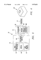
- FIG. 3 is a function block diagram of the computer system shown in FIG. 1.
- FIG. 4 is a perspective view of an one-dimensional actuator according to the present invention.
- FIG. 1 is a perspective view of a computer system 10 according to the present invention.
- the computer system 10 comprises a monitor 12, a computerl6 and a keyboard 18.
- the monitor 12 shows a cursor 14 over where a text character will be entered.
- the keyboard 18 comprises a plurality of text keys 22, a two-dimensional actuator 20 installed approximately at a center portion under the text keys 22, and a numerical keypad 19 installed at the right side of the keyboard 18.
- the actuator 20 is a track ball which can be actuated by using a thumb while the other four fingers can work with the text keys 22 at the same time.
- the numerical keypad 19 comprises four direction keys 24 26 28 30, and four control keys: page-up key 32 page-down key 34 home key 36 and end key 38.
- FIG. 2 is a side section view 2--2 of the keyboard 18 shown in FIG. 1.
- the actuator 20 is a track ball which is elastically installed inside a recess 41 located at the front of the keyboard 18 and can be slightly pressed downward.
- a switch 40 and several springs 42 are installed inside the recess 41 under the actuator 20 for elastically supporting the actuator 20 upward.
- the switch 40 can be triggered by pressing the actuator 20 downward.
- a user can either interact with the actuator 20 without pressing the actuator 20 downward, or interact with the actuator 20 while pressing the actuator 20 downward at the same time.
- FIG. 3 is a function block diagram of the computer system 10 shown in FIG. 1.
- the computer system 10 comprises a monitor 12 for showing screen, a keyboard 18 for converting inputs entered by a user into corresponding signals, and a computer 16 connected between the monitor 12 and the keyboard 18.
- the computer 16 comprises a memory 48 for storing programs and data, a display control program 58 stored in the memory 48 for controlling the screen shown on the monitor 12 by the signals generated by the keyboard 18, and a processor 46 for executing the programs stored in the memory 48.
- the display control program 58 is formed by several commonly used program models (not shown), such as BIOS (basic input output system), window-based operating system, text-editing program executed under the operating system, etc.
- the keyboard 18 comprises a two-dimensional actuator 20, a switch 40, a key matrix circuit 44, and an encoding circuit 52 connected to the actuator 20, the switch 40, and the key matrix circuit 44.
- the key matrix circuit 44 comprises the text keys 22, four direction keys 24 26 28 30, and four control keys: page-up key 32 page-down key 34 home key 36 end key 38 shown in FIG. 1.
- the text keys 22 connected to the encoding circuit 52 are used for generating text signals. When the encoding circuit 52 detects any of the text keys 22 is being pressed downward, a corresponding text signal will be generated by the encoding circuit 52.
- the four direction keys 24 26 28 30 connected to the encoding circuit 52 are associated with four predefined directions which are up down left and right directions.
- the four predefined directions are perpendicular or opposite to each other.
- the encoding circuit 52 will generate a corresponding direction signal.
- the actuator 20 comprises four predefined directions: up down left and right, which are the same as the four direction keys 24 26 28 30.
- the actuator 20 can generate two-dimensional signals when it is being actuated, and the encoding circuit 52 can relate each of the two-dimensional signals to the correspondent predefined direction.
- the four predefined directions of the actuator 20 associated with the switch 40 can be used to generate the four direction signals of the four direction keys 24 26 28 30 or the four control signals of the four control keys.
- the switch 40 is not being pressed by the actuator 20, the four predefined directions of the actuator 20 are used to generate the four direction signals of the four direction keys 24 26 28 30.
- the four predefined directions of the actuator 20 are used to generate the four control signals of the four control keys: page-up key 32 page-down key 34 home key 36 and end key 38.
- the up and down directions can be used to generate the page-up and page-down signals of the page-up key 32 and page-down key 34
- the left and right directions can be used to generate the home and end signals of home key 36 and end key 38.
- the encoding circuit 52 will convert the two-dimensional signals generated by the actuator 20 into correspondent direction signals or control signals depending on whether the switch 40 is being pressed by the actuator 20 or not.
- the ways to convert a two dimensional signal into correspondent direction signal or control signal are different.
- the two dimensional signals generated by the actuator 20 can be represented by ( ⁇ X, ⁇ Y) where +X -X +Y and -Y represent the predefined right left up and down directions.
- the encoding circuit 52 When converting a two-dimensional signal ( ⁇ X, ⁇ Y) into correspondent direction signal(s), the encoding circuit 52 will convert ⁇ X and ⁇ Y into correspondent direction signals. However, when converting a two-dimensional signal ( ⁇ X, ⁇ Y) into correspondent control signal, only one control signal will be generated each time. For example, it is not permitted generating a page-up signal and a home signal at the same time.
- the encoding circuit 52 can select one of the two parameters ⁇ X and ⁇ Y and converts it into correspondent control signals. For example, the encoding circuit 52 can select the parameter which has the largest absolute value.
- the direction or control signals generated by the encoding circuit 52 by actuating the actuator 20 and switch 40 are the same as those generated by the direction keys 24 26 28 30 or the four control keys. Compared with the numerical keypad 19, the actuator 20 and switch 40 only change the method of generating these direction or control signals.
- the display control program 58 stored in the computer 16 can directly process these signals without any modification, and any prior art computer can work with keyboard 18 directly without changing its hardware or software as long as it is equipped with a standard keyboard port.
- FIG. 4. shows an alternative one-dimensional actuator 60 of the present invention.
- the two-dimensional actuator 20 of the keyboard 18 shown in FIGS. 1 and 2 can be replaced by the one-dimensional actuator 60 which is a rotatable wheel and can be rotated toward upward or downward direction.
- the one-dimensional actuator 60 associated with the switch 40, can be used to generate any two of the four direction signals or control signals.
- the two directions of the actuator 60 can be associated with any two opposite direction keys of the four direction keys 24 26 28 30, such as the up and down direction keys, to generate correspondent direction signals, or associated with any two opposite control keys of the four control keys 32 34 36 38, such as the page-up key 32 and page-down key 34, to generate correspondent control signals.
Abstract
Description
Claims (9)
Priority Applications (1)
| Application Number | Priority Date | Filing Date | Title |
|---|---|---|---|
| US08/928,912 US5973622A (en) | 1997-09-12 | 1997-09-12 | Keyboard with a two-dimensional actuator for generating direction signals |
Applications Claiming Priority (1)
| Application Number | Priority Date | Filing Date | Title |
|---|---|---|---|
| US08/928,912 US5973622A (en) | 1997-09-12 | 1997-09-12 | Keyboard with a two-dimensional actuator for generating direction signals |
Publications (1)
| Publication Number | Publication Date |
|---|---|
| US5973622A true US5973622A (en) | 1999-10-26 |
Family
ID=25457000
Family Applications (1)
| Application Number | Title | Priority Date | Filing Date |
|---|---|---|---|
| US08/928,912 Expired - Lifetime US5973622A (en) | 1997-09-12 | 1997-09-12 | Keyboard with a two-dimensional actuator for generating direction signals |
Country Status (1)
| Country | Link |
|---|---|
| US (1) | US5973622A (en) |
Cited By (10)
| Publication number | Priority date | Publication date | Assignee | Title |
|---|---|---|---|---|
| US20010011995A1 (en) * | 1998-09-14 | 2001-08-09 | Kenneth Hinckley | Method for providing feedback responsive to sensing a physical presence proximate to a control of an electronic device |
| US20010015718A1 (en) * | 1998-09-14 | 2001-08-23 | Hinckley Kenneth P. | Method for displying information responsive to sensing a physical presence proximate to a computer input device |
| US6333753B1 (en) | 1998-09-14 | 2001-12-25 | Microsoft Corporation | Technique for implementing an on-demand display widget through controlled fading initiated by user contact with a touch sensitive input device |
| US6396477B1 (en) | 1998-09-14 | 2002-05-28 | Microsoft Corp. | Method of interacting with a computer using a proximity sensor in a computer input device |
| US6456275B1 (en) * | 1998-09-14 | 2002-09-24 | Microsoft Corporation | Proximity sensor in a computer input device |
| US20020196234A1 (en) * | 2001-06-25 | 2002-12-26 | Gray Robin S. | Computer mouse system and method of using |
| US20040119697A1 (en) * | 1999-06-23 | 2004-06-24 | Nec Corporation | Keyboard device capable of automatically changing function of certain key without pressing a specific key |
| US7156693B2 (en) * | 2003-01-22 | 2007-01-02 | Kabushiki Kaisha Toshiba | Electronic apparatus with pointing device on the housing |
| WO2010033582A2 (en) * | 2008-09-16 | 2010-03-25 | Angell-Demmel North America Ltd. | Multi-layer integral keypad |
| US20110047456A1 (en) * | 2009-08-19 | 2011-02-24 | Keisense, Inc. | Method and Apparatus for Text Input |
Citations (5)
| Publication number | Priority date | Publication date | Assignee | Title |
|---|---|---|---|---|
| US4575591A (en) * | 1984-04-23 | 1986-03-11 | Lugaresi Thomas J | Joystick attachment for a computer keyboard |
| US4680577A (en) * | 1983-11-28 | 1987-07-14 | Tektronix, Inc. | Multipurpose cursor control keyswitch |
| US5021771A (en) * | 1988-08-09 | 1991-06-04 | Lachman Ronald D | Computer input device with two cursor positioning spheres |
| US5521596A (en) * | 1990-11-29 | 1996-05-28 | Lexmark International, Inc. | Analog input device located in the primary typing area of a keyboard |
| US5694123A (en) * | 1994-09-15 | 1997-12-02 | International Business Machines Corporation | Keyboard with integrated pointing device and click buttons with lock down for drag operation in a computer system with a graphical user interface |
-
1997
- 1997-09-12 US US08/928,912 patent/US5973622A/en not_active Expired - Lifetime
Patent Citations (5)
| Publication number | Priority date | Publication date | Assignee | Title |
|---|---|---|---|---|
| US4680577A (en) * | 1983-11-28 | 1987-07-14 | Tektronix, Inc. | Multipurpose cursor control keyswitch |
| US4575591A (en) * | 1984-04-23 | 1986-03-11 | Lugaresi Thomas J | Joystick attachment for a computer keyboard |
| US5021771A (en) * | 1988-08-09 | 1991-06-04 | Lachman Ronald D | Computer input device with two cursor positioning spheres |
| US5521596A (en) * | 1990-11-29 | 1996-05-28 | Lexmark International, Inc. | Analog input device located in the primary typing area of a keyboard |
| US5694123A (en) * | 1994-09-15 | 1997-12-02 | International Business Machines Corporation | Keyboard with integrated pointing device and click buttons with lock down for drag operation in a computer system with a graphical user interface |
Cited By (18)
| Publication number | Priority date | Publication date | Assignee | Title |
|---|---|---|---|---|
| US7602382B2 (en) | 1998-09-14 | 2009-10-13 | Microsoft Corporation | Method for displaying information responsive to sensing a physical presence proximate to a computer input device |
| US6396477B1 (en) | 1998-09-14 | 2002-05-28 | Microsoft Corp. | Method of interacting with a computer using a proximity sensor in a computer input device |
| US20010011995A1 (en) * | 1998-09-14 | 2001-08-09 | Kenneth Hinckley | Method for providing feedback responsive to sensing a physical presence proximate to a control of an electronic device |
| US7256770B2 (en) | 1998-09-14 | 2007-08-14 | Microsoft Corporation | Method for displaying information responsive to sensing a physical presence proximate to a computer input device |
| US6456275B1 (en) * | 1998-09-14 | 2002-09-24 | Microsoft Corporation | Proximity sensor in a computer input device |
| US20010015718A1 (en) * | 1998-09-14 | 2001-08-23 | Hinckley Kenneth P. | Method for displying information responsive to sensing a physical presence proximate to a computer input device |
| US6559830B1 (en) | 1998-09-14 | 2003-05-06 | Microsoft Corporation | Method of interacting with a computer using a proximity sensor in a computer input device |
| US7358956B2 (en) | 1998-09-14 | 2008-04-15 | Microsoft Corporation | Method for providing feedback responsive to sensing a physical presence proximate to a control of an electronic device |
| US6333753B1 (en) | 1998-09-14 | 2001-12-25 | Microsoft Corporation | Technique for implementing an on-demand display widget through controlled fading initiated by user contact with a touch sensitive input device |
| US20040119697A1 (en) * | 1999-06-23 | 2004-06-24 | Nec Corporation | Keyboard device capable of automatically changing function of certain key without pressing a specific key |
| US20020196234A1 (en) * | 2001-06-25 | 2002-12-26 | Gray Robin S. | Computer mouse system and method of using |
| US6970159B2 (en) * | 2001-06-25 | 2005-11-29 | Gray Robin S | Mouse printing device with integrated touch pad buttons |
| US7156693B2 (en) * | 2003-01-22 | 2007-01-02 | Kabushiki Kaisha Toshiba | Electronic apparatus with pointing device on the housing |
| WO2010033582A2 (en) * | 2008-09-16 | 2010-03-25 | Angell-Demmel North America Ltd. | Multi-layer integral keypad |
| WO2010033582A3 (en) * | 2008-09-16 | 2010-06-03 | Angell-Demmel North America Ltd. | Multi-layer integral keypad |
| US8411038B2 (en) | 2008-09-16 | 2013-04-02 | Angell-Demmel North America Corporation | Multi-layer integral keypad |
| US9110515B2 (en) * | 2009-08-19 | 2015-08-18 | Nuance Communications, Inc. | Method and apparatus for text input |
| US20110047456A1 (en) * | 2009-08-19 | 2011-02-24 | Keisense, Inc. | Method and Apparatus for Text Input |
Similar Documents
| Publication | Publication Date | Title |
|---|---|---|
| US8659552B2 (en) | Handheld electronic device | |
| US5748185A (en) | Touchpad with scroll and pan regions | |
| US8405601B1 (en) | Communication system and method | |
| JP3630153B2 (en) | Information display input device, information display input method, and information processing device | |
| JP3691896B2 (en) | Computer | |
| CA2615359C (en) | Virtual keypad input device | |
| JP6115867B2 (en) | Method and computing device for enabling interaction with an electronic device via one or more multi-directional buttons | |
| US20030189553A1 (en) | Rapid entry of data and information on a reduced size input area | |
| US6046728A (en) | Keyboard actuated pointing device | |
| WO1998000775A9 (en) | Touchpad with scroll and pan regions | |
| EP2616908A2 (en) | Methods of and systems for reducing keyboard data entry errors | |
| AU2005203634A1 (en) | Integrated keypad system | |
| JP2000056877A (en) | Touch panel type layout free keyboard | |
| US5973622A (en) | Keyboard with a two-dimensional actuator for generating direction signals | |
| US9606633B2 (en) | Method and apparatus for input to electronic devices | |
| KR101808774B1 (en) | Virtual keyboard strucutre for mobile device, method of inputting character using virtual keyboard for mobile device, computer readable storage media containing program for executing the same | |
| EP0591083A1 (en) | Method and apparatus for interacting with a user interface for a pen-based computing system | |
| EP0895153B1 (en) | Data input device and method | |
| US20030080972A1 (en) | Electronic device | |
| KR100469704B1 (en) | Mobile phone user interface device with trackball | |
| KR100503056B1 (en) | Touch pad processing apparatus, method thereof and touch pad module in computer system | |
| KR100292014B1 (en) | Apparatus for input of personal computer | |
| CN212135402U (en) | Touch keyboard | |
| US20010040557A1 (en) | Wrist rest having a two-handed scrolling mode switch | |
| JP2500283B2 (en) | Virtual space keyboard device |
Legal Events
| Date | Code | Title | Description |
|---|---|---|---|
| AS | Assignment |
Owner name: ACER PERIPHERALS, INC., TAIWAN Free format text: ASSIGNMENT OF ASSIGNORS INTEREST;ASSIGNOR:CHIANG, TZU-PANG;REEL/FRAME:008711/0718 Effective date: 19970817 |
|
| STCF | Information on status: patent grant |
Free format text: PATENTED CASE |
|
| FEPP | Fee payment procedure |
Free format text: PAYOR NUMBER ASSIGNED (ORIGINAL EVENT CODE: ASPN); ENTITY STATUS OF PATENT OWNER: LARGE ENTITY Free format text: PAYER NUMBER DE-ASSIGNED (ORIGINAL EVENT CODE: RMPN); ENTITY STATUS OF PATENT OWNER: LARGE ENTITY |
|
| FPAY | Fee payment |
Year of fee payment: 4 |
|
| AS | Assignment |
Owner name: BENQ CORPORATION, TAIWAN Free format text: CHANGE OF NAME;ASSIGNORS:ACER PERIPHERALS, INC.;ACER COMMUNICATIONS & MULTIMEDIA INC.;REEL/FRAME:014567/0715 Effective date: 20011231 |
|
| FPAY | Fee payment |
Year of fee payment: 8 |
|
| AS | Assignment |
Owner name: QISDA CORPORATION, TAIWAN Free format text: CHANGE OF NAME;ASSIGNOR:BENQ CORPORATION;REEL/FRAME:020704/0867 Effective date: 20070831 |
|
| FPAY | Fee payment |
Year of fee payment: 12 |