US5982412A - Coaxial testing and provisioning network interface device - Google Patents
Coaxial testing and provisioning network interface device Download PDFInfo
- Publication number
- US5982412A US5982412A US08/981,179 US98117997A US5982412A US 5982412 A US5982412 A US 5982412A US 98117997 A US98117997 A US 98117997A US 5982412 A US5982412 A US 5982412A
- Authority
- US
- United States
- Prior art keywords
- network
- interface unit
- broadband
- network interface
- communication
- Prior art date
- Legal status (The legal status is an assumption and is not a legal conclusion. Google has not performed a legal analysis and makes no representation as to the accuracy of the status listed.)
- Expired - Lifetime
Links
Images


Classifications
-
- H—ELECTRICITY
- H04—ELECTRIC COMMUNICATION TECHNIQUE
- H04H—BROADCAST COMMUNICATION
- H04H20/00—Arrangements for broadcast or for distribution combined with broadcast
- H04H20/12—Arrangements for observation, testing or troubleshooting
-
- H—ELECTRICITY
- H04—ELECTRIC COMMUNICATION TECHNIQUE
- H04H—BROADCAST COMMUNICATION
- H04H20/00—Arrangements for broadcast or for distribution combined with broadcast
- H04H20/65—Arrangements characterised by transmission systems for broadcast
- H04H20/76—Wired systems
- H04H20/77—Wired systems using carrier waves
- H04H20/78—CATV [Community Antenna Television] systems
-
- H—ELECTRICITY
- H04—ELECTRIC COMMUNICATION TECHNIQUE
- H04N—PICTORIAL COMMUNICATION, e.g. TELEVISION
- H04N17/00—Diagnosis, testing or measuring for television systems or their details
-
- H—ELECTRICITY
- H04—ELECTRIC COMMUNICATION TECHNIQUE
- H04N—PICTORIAL COMMUNICATION, e.g. TELEVISION
- H04N7/00—Television systems
- H04N7/10—Adaptations for transmission by electrical cable
- H04N7/102—Circuits therefor, e.g. noise reducers, equalisers, amplifiers
-
- H—ELECTRICITY
- H04—ELECTRIC COMMUNICATION TECHNIQUE
- H04N—PICTORIAL COMMUNICATION, e.g. TELEVISION
- H04N7/00—Television systems
- H04N7/14—Systems for two-way working
- H04N7/141—Systems for two-way working between two video terminals, e.g. videophone
- H04N7/148—Interfacing a video terminal to a particular transmission medium, e.g. ISDN
Definitions
- This invention relates to the cable television field and, more particularly, to methods and devices for testing and provisioning a cable television system.
- the cable television (CATV) industry has evolved over the years from just providing remote areas with television signals, to a full-fledged industry providing entertainment to the home.
- technology has increased in complexity with reverse channel capability and bandwidth growing from 400 MHz to 750 MHz, and now to 1 GHz.
- the quality of signals has also improved with the deployment of fiber optic systems which drive the signals deep into each neighborhood. From there the signal is carried on coaxial cable, and tapped for the customer drop. Even with the evolution of the technology in signal quality and channel carrying capacity, there are a number of routine testing and provisioning activities which still require a costly dispatch to handle.
- Testability of the coaxial signal quality at the customer interface is still an on-site type of test procedure. While trunk and feeder coaxial signals have been capable of remote monitoring for years, tests on the coaxial cable drop today are usually a manual function requiring a technician to visit the customer and perform diagnostics using portable test equipment. This is undesirable from a service standpoint since it can take a protracted amount of time for a technician to be dispatched, identify the trouble and repair it if required. From a network operator's standpoint, the customers' coaxial cable drops may represent over 50% of the deployed miles of coaxial cable in a newer broadband delivery system, which makes these drops a prime target for testability.
- Provisioning issues associated with the chum rate of customers and illegal connections to the system are a major concern. Even with a small monthly percentage of churn, the number of dispatches required for disconnects and reconnects equates to a sizable annual maintenance and administrative expense. Additionally, the lost monthly revenue associated with illegal connections to the CATV system can amount to a significant lost profit potential. Even with a low churn rate and a small percentage of illegal connections, these costs can amount to millions of dollars per year.
- the apparatus includes a first network interface unit for facilitating communication between a first communication network and an end use apparatus utilizing a first transmission medium, such as a coaxial wire.
- a second network interface unit facilitates communication between a second communications network and the first network interface utilizing a second transmission medium, such as a telephone wire.
- a central control and testing center is connected between the first and second communications networks for transmitting and receiving a signal utilizing at least one of the first and second transmission mediums.
- the first network interface unit is connected for receiving the signal from the central control and testing center on one of the first and second transmission mediums and for responding thereto by transmitting a response signal to the central control and testing center utilizing the other of the first and second transmission mediums.
- the first network interface unit further includes means for receiving the signal on one of the first and second transmission medium and for responding thereto utilizing the one of the first and second transmission medium.
- a transceiver of the end use apparatus facilitates communication between the end use apparatus and at least one of the first and second communication networks through one of (i) the respective first and second network interface units or (ii) the first network interface unit.
- a means is provided for connecting the first communication network to one of the end use device and a termination in response to receipt of a control signal transmitted on one of the first and second transmission medium.
- the first network interface unit includes a grade of service device and a reverse transmission filter that are selectably connectable between the first communication network and the end use device in response to the control signal.
- the first network interface unit also includes a test circuit for testing the quality of signals from at least one of the first communication network and the end use device. The test circuit is connectable to at least one of the first communication network and the end use device in response to the control signal.
- a network interface unit for connection between a telephone network and a broadband network.
- the network interface unit includes a telephone network communication option for transmitting and receiving telephone signals over the telephone network and for converting telephone signals to digital signals.
- a controller is connected to the telephone network communication option for receiving digital signals therefrom.
- a switching means is connected between the broadband network and the controller. The controller causes the switching means to selectively connect or disconnect the broadband network to or from the customer equipment in response to the receipt of a telephone signal by the telephone network communication option.
- the network interface unit includes a termination connected to the switching means and a test circuit connected between the controller and the switching means.
- the controller causes the switching means, in response to the receipt of a telephone signal by the telephone network communication option, to connect the broadband network to one of the termination and the customer equipment; and/or connect the test circuit to the broadband network and the customer equipment.
- the test circuit converts a signal on the broadband network into a digital signal for use by the controller in measuring the quality of signals on the broadband network.
- a means is provided for selecting the frequency of the signal to be converted to a digital signal.
- the controller further includes means for isolating the customer equipment from the broadband network and the test circuit and means for isolating the broadband network from the customer equipment and the test circuit.
- the controller includes means for transmitting digital signals to the telephone communications option wherein the digital signals are converted to telephone signals for transmission over the telephone network.
- the network interface unit further includes a broadband communications option connected between the controller and the broadband network for receiving a broadband signal therefrom and for converting the received broadband signal into a digital signal useable by the controller.
- the controller causes the switching means to connect the broadband network to one of the customer equipment and the termination in response to the controller receiving a signal from one of the telephone and the broadband network.
- the controller responds to the broadband signal over (i) the other of the telephone network and broadband communications options or (ii) the one of the telephone and broadband network.
- the network interface unit has encryption key and unique address for selective communication therewith via at least one of the telephone and broadband network.
- a broadband control signal is provided on one of a telephone line or the broadband line.
- the broadband line is connected to one or more of a customer's equipment, a test circuit and a termination in response to the control signal.
- a response to the control signal is issued over one of the telephone line and the broadband line.
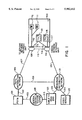
- FIG. 1 is a block diagram of a broadband coaxial delivery system including a coaxial network interface unit in accordance with the present invention
- FIG. 2 is a schematic diagram of internal circuitry of the coaxial network interface unit of FIG. 1;
- FIGS. 3A-3C are schematic diagrams showing provisioning service states of the coaxial network interface unit of FIG. 2;
- FIGS. 4A-4C are schematic diagrams showing testing states of the coaxial network interface unit of FIG. 2.
- FIG. 5 is a schematic view of the coaxial network interface unit of FIG. 2 including a switching device having a plurality of switching mechanisms for test access and allowing or denying delivery of signals between the broadband coaxial network and a plurality of customer equipment.
- FIG. 1 is a block diagram showing a system of the present invention using a broadband coaxial delivery system and a public switched telephone network (PSTN).
- PSTN public switched telephone network
- the PSTN 101 is shown to communicate with a PSTN distribution network 106 via telephone lines 102 or other telephone facilities.
- the PSTN 101 also communicates with a centralized control and testing center 105 via telephone lines 103.
- a subscriber location 109 such as a private residence, is connected to the PSTN distribution network 106 via telephone lines 107 which are connected to a telephone network interface unit 108 at the private residence 109.
- telephone wiring 110, 113 connects the telephone interface unit 108 to telephone instruments 111 and 112, and other devices, such as television 115.
- a coaxial network interface unit 116 mounted at the private residence 109, is connected via inside coaxial wiring 114, 117 to television sets 115, 118, respectively, or other customer equipment such as a Video Cassette Recorder (VCR), set top decoder, cable modem and the like.
- the coaxial network interface unit 116 is also connected to the telephone network interface unit 108 via telephone lines 119 in order to provide the PSTN 101 access to the coaxial network interface unit 116.
- the coaxial network interface unit 116 is connected to a broadband distribution network 121 via broadband line 120 or other broadband facilities, which in a preferred embodiment is coaxial cable.
- the broadband distribution network 121 may also be connected to one or a plurality of systems through a cable television head end 122 connected to the broadband distribution network 121 via broadband line 123.
- the cable television head end 122 is connected to the central control and testing center 105 for communication therewith via broadband line 213.
- the broadband distribution network 121 may also be connected to a video server 125 via broadband line 124.
- the broadband distribution network 121 may be connected to the PSTN distribution network 106 via telephone lines 126.
- Other broadband subscriber locations (not shown) have similar connections to the PSTN 101 and the broadband distribution network 121.
- each subscriber has customer equipment 137, such as a television 115 or other equipment, connected to the coaxial network interface unit 116 via inside coaxial cable 114.
- This equipment 137 may be equipped with circuitry designed for receiving signals in the forward direction from the broadband distribution network 121, and for transmitting signals in the reverse direction back to the broadband distribution network 121.
- a testing methodology is provided for measuring frequencies in both the forward and reverse direction and a switching methodology for enabling varying levels of service to the customer equipment and to enable or disable customer equipment reverse transmission into the broadband network. Access for measurement purposes is provided via switching device 141 connected between the broadband distribution network 121 and the customer equipment 137 via broadband line 120 and inside coaxial wiring 114.
- Frequencies of broadband signals from the broadband distribution network 121 are, without limitation, typically in the 45 to 1000 MHz range.
- the customer equipment 137 is capable of transmitting or receiving one or a plurality of signals to or from the broadband distribution network 121 via switching device 141.
- Option 1 derives power from the telephone lines 119.
- the individual circuits of the coaxial network interface unit 116 receive operating voltage from DC power provided to power supply 146 from the PSTN 101 via telephone lines 119 and leads 145.
- the power supply 146 receives the DC voltage on leads 145 and provides a local power output 177 for the logic, measurement and switching mechanism operations.
- Option 2 derives power from the broadband line 120.
- the individual circuits of the coaxial network interface unit 116 receive operating voltage from AC or DC power provided to power supply 210 from the broadband distribution network 121 via broadband line 120 and leads 209.
- the power supply 210 receives the provided AC or DC voltage and provides a local power output 211 for the logic, measurement and switching mechanism operations.
- Option 3 derives power from a power utility outlet 204 at the private residence 109.
- the coaxial network interface unit 116 receives AC or DC voltage from the power utility outlet 204 via leads 203 fed through a power inserter 202 onto the coaxial leads 201.
- the power inserter 202 blocks power from the inside coaxial wiring 114 while providing for the bi-directional passing of broadband signals between the customer equipment 137 and switching device 141, via coaxial wiring 114 and coaxial leads 201.
- the AC or DC voltage impressed on the coaxial leads 201 is fed to the power supply 205 via leads 206.
- the power supply 205 provides a local power output 207 for the logic, measurement and switching mechanism operations.
- the present invention may include one, or more of the above powering options to increase deployment flexibility. For safety purposes, all powering options incorporate grounding capability. Moreover, the coaxial network interface unit 116 is grounded to earth via bonding to the power utility ground or to a ground rod or other suitable ground via leads 138.
- the first option is command, control and data transfer solely over the PSTN 101.
- the telephone lines 107, 119, the PSTN distribution network 106 and the telephone network interface unit 108 are connected for carrying typical bidirectional telephone communications signals between the PSTN 101 and the coaxial network interface unit 116.
- the operation of the coaxial network interface unit 116 is controllable via signals received from the centralized control center 105 through the PSTN 101 on telephone lines 119.
- the PSTN 101 is connected to a PSTN communications option 144 of coaxial network interface unit 116.
- the PSTN communications option 144 includes low pass filter 147, hybrid 149, receiver 153 and transmitter 152. Control signals to the PSTN communications option 144 sent by the PSTN 101 via telephone lines 119 are fed to the low pass filter 147. The output of the low pass filter 147 is sent via leads 148 to the hybrid 149 where the signals are split for transmit and receive.
- the hybrid 149 provides the analog telephone signals from the control and testing center 105 to the receiver circuitry 153 via leads 151.
- the receiver 153 converts the analog telephone signals to digital signals and provides the digital signals via leads 155 to a controller 179.
- the controller 179 includes microprocessor 156 for analyzing the incoming digital signals and acting thereon. Controller 179 also includes driver 158 to be discussed in greater detail hereinafter. Responses to the central control and testing center 105 are sent from the microprocessor 156 to the transmitter 152 via leads 154. The transmitter 152 converts the digital signals from the microprocessor 156 to an analog telephone signal format and sends the telephone signals via leads 150 to the hybrid 149 and through low pass filter 147 where the responses are sent back to the PSTN 101 and to the central control and testing center 105.
- the second option is command, control and data transfer solely over the broadband line 120.
- the broadband line 120 and the broadband distribution network 121 are connected for carrying bi-directional broadband signals between the coaxial network interface unit 116 and the CATV head end 122 via broadband lines 123 and 120.
- the coaxial network interface unit 116 is controlled from the central control and testing center 105 via broadband control signals provided from the CATV head end 122. Control signals received by the coaxial network interface unit 116 from the central control and testing center 105 via the CATV head end 122 control the operation of the circuitry in the coaxial network interface unit 116.
- control signals sent via the CATV head end 122 are fed to a broadband communications option 212 of coaxial network interface unit 116 via leads 213.
- the broadband communications option 212 includes a diplexer 214 wherein the control signals are split for transmit and receive.
- the diplexer 214 routes control signals from leads 213 to RF receiver 217 via leads 215.
- the receiver 217 converts the broadband signals sent from the central control and testing center 105 to digital signals and sends the digital signals via leads 219 to the microprocessor 156 wherein the incoming communications are analyzed and acted upon.
- Responses to the central control and testing center 105 are sent from the microprocessor 156 via leads 220 to a transmitter 218.
- the transmitter 218 converts these digital signals to broadband format and sends them via leads 216 to the diplexer 214 where the responses are sent back via leads 213 and broadband line 120 to the CATV head end 122 and to the central control and testing center 105.
- the third option is command, control and data transfer from the central control and testing center 105 to the coaxial network interface unit 116 over one of the broadband line 120 or the telephone lines 107 with a return path from the coaxial network interface unit 116 to the central control and testing center 105 being provided over the other one of the broadband line 120 and the telephone lines 107.
- the broadband distribution network 121 routes broadband signals from the CATV head end 122 to the coaxial network interface unit 116 via broadband line 120.
- a return path from the coaxial network interface unit 116 is provided to the central control and testing center 105 through the PSTN 101 via telephone lines 107.
- the coaxial network interface unit 116 is controlled from the central control and testing center 105 via broadband control signals transmitted on broadband line 120.
- the control signals are provided to the coaxial network interface unit 116 via the telephone line 107 with a return path being provided via broadband line 120.
- Broadband control signals sent via broadband line 120 are fed through a first switch mechanism 161 of switching device 141 and on to a second switch mechanism 163 via leads 162.
- Switching mechanisms 161, 163 route the control signals to test circuitry 180 via leads 164.
- Test circuitry 180 includes high pass filter 166, tunable band detector 168, A/D converter 175, phase-locked loop (PLL) D/A converter 173 and oscillator (OSC) 171.
- the broadband control signals from switch mechanism 163 are routed to the high pass filter 166 and to the tunable broadband detector 168 via leads 167. This path is the same as the measurement path which will be described in further detail hereinafter.
- the tunable broadband detector 168 is tuned to the frequency of the control signals and demodulates the control signals to baseband levels that are sent via leads 169 to A/D converter 175 for digitization and reception at the microprocessor 156 of the controller 179 via leads 176 where the incoming communications are analyzed and acted upon.
- Responses to the broadband control signals are sent from the microprocessor 156 via leads 154 to the transmitter 152 of the PSTN communications option 144.
- the transmitter 152 converts these digital signals to an analog telephone signal format and sends the telephone signals via leads 150 to the hybrid 149 and through low pass filter 147 where the responses are sent back into the PSTN 101 and to the central control and testing center 105.
- the microprocessor 156 of controller 179 responds to the broadband control signals via the broadband communications option 212 in the manner set forth above in conjunction with the second communications option.
- An encryption key and unique address for each coaxial network interface unit 116 on a broadband network may also be provided to enhance security in the broadband network.
- the central control and testing center 105 may also provide the appropriate commands to enable manual or automatic sequencing of coaxial network interface unit 116 testing and provisioning activities.
- Switching device 141 contains the first switching mechanism 161 under the control of microprocessor 156.
- the microprocessor 156 sends commands to a driver 158 via leads 157 to actuate the switching mechanism 161 via leads 160.
- the switching mechanism 161 is connected via leads 162 to the second switching mechanism 163, which is also controlled by the microprocessor 156.
- Control signals from the microprocessor 156 are sent via leads 157 to the driver 158 to actuate the switching mechanism 163 via leads 159.
- Switching mechanisms 161, 163 may be implemented with mechanical relays or with solid state devices.
- the provisioning capabilities of the coaxial network interface device are controlled by the microprocessor 156 under the command of the central control and testing network center 105 as set forth above.
- the central control and testing center 105 issues a command to the microprocessor 156 to set the switching mechanism 161 to route the appropriate level of service and/or filtering from the broadband distribution network 121 through the switching mechanism 161 to the customer's inside wiring 114, 117.
- the central control and testing center 105 issues a command to the microprocessor 156 to set the switching mechanisms 161 and 163 to route the connection from the broadband distribution network 121 through the other leg of the switching device 141, to the 75 ohm termination 165, as illustrated in FIG. 2.
- the testing capabilities of the coaxial network interface unit 116 are controlled by the microprocessor 156 under the command of the central control and testing center 105, as previously detailed.
- the central control and testing center 105 issues a command to the microprocessor 156 to set the switching mechanisms 161 and 163 so that a path is formed between the test circuitry 180 and either the broadband line 120 or the customer's inside wiring 114.
- Frequencies from, without limitation, 5 MHz to 1000 MHz are presentable to the tunable broadband detector 168 from the high pass filter 166 via leads 167.
- the tunable detector 168 then performs measurements on the signals presented on leads 167.
- the output of the tunable detector 168 is connected via leads 169 to an analog-to-digital (A/D) converter 175.
- the A/D converter 175 then sends digital information to the microprocessor 156 via leads 176 for analysis and processing. Based upon software controlling the microprocessor 156, the measurements are converted into signals which are fed from the microprocessor 156 to transmitter 152 or transmitter 218 via leads 154 or 220 for transmission back into the central control and testing center 105, as previously described.
- a voltage controlled oscillator OSC 171 is provided under the control of the microprocessor 156. Signals from the microprocessor 156 are sent via leads 174 to the PLL D/A converter 173 which sends a difference voltage via leads 172 to the OSC 171 to change frequency selection. The output frequency from the OSC 171 is fed via leads 170 to tunable broadband detector 168.
- Measurements performed by the tunable detector 168 include measuring signal quality, such as, without limitation, signal levels, carrier-to-noise ratios, intermodulation, hum, AC voltage, DC voltage, resistance or capacitance.
- the broadband line 120 is connected to the switching device 141 via connector 140 and the inside wiring 114 is connected to the switching device 141 via connector 142.
- the central control and testing center 105 issues a command to the coaxial network interface unit 116 to set the switching mechanism 161 so that signals on broadband line 120 pass through a grade of service device 223, associated with switching device 141, to the customer's inside wiring 114.
- Also shown, but not connected in this service state are the paths to the 75 ohm termination 165, the leads 164 to the test circuitry 180 and a reverse transmission filter 222. In this service state, two-way transmission between the customer's equipment 137 and the CATV head end 122 is provided.
- the central network control and testing center 105 issues a command to the coaxial network interface unit 116 to set the switching mechanisms 161 and 163 so that a broadband signal on the broadband line 120 is routed to the other leg of the switching device 141 through leads 162 to the second switching mechanism 163.
- the second switching mechanism 163 is set to route the broadband signal to the 75 ohm termination 165.
- the customer's equipment 137 is isolated from the broadband line 120 and appropriate electrical termination is provided for the broadband line 120.
- the central control and testing center 105 issues a command to the coaxial network interface unit 116 to set the switching mechanism 161 so that the broadband line 120 is connected to the inside wiring 114 via the grade of service device 223 and the reverse transmission filter 222, embedded in the switching device 141. Also shown, but not connected in this service state, are the paths to the 75 ohm termination 165 and the leads 164 to the test circuitry 180. In this service state, one-way transmission from the CATV head end 122 to the customer's equipment 137 is provided.
- the switching mechanism 161 is set to route a signal on the broadband line 120 through the grade of service device 223, to the second switching mechanism 163 via leads 162.
- the second switching mechanism 163 is set to route the signal to test circuitry 180 which measures the quality of signals on the broadband line 120.
- the first switching mechanism 161 is set to connect the broadband line 120 to the grade of service device 223 which, in turn, is connected to the inside wiring 114 and the second switching mechanism 163.
- the grade of service device 223 is utilized to provide an appropriate service option.
- the second switching mechanism 163, fed by leads 162, routes signals from grade of service device 223 to the test circuitry 180. In this manner, testing can be accomplished on an in-service basis and measurements can be taken on the two-way transmissions between the customer's equipment 137 and the CATV head end 122.
- the switching mechanism 161 is set to route a signal from the inside wiring 114 to the second switching mechanism 163 through leads 162.
- Switching mechanism 163 is set to route the signal to the test circuitry 180. In this manner, the test circuitry 180 can measure the quality of signals sent on inside wiring 114 by customer equipment 137.
- the broadband line 120 serves a multi-residence, wherein each subscriber has customer equipment 137.
- customer equipment 137 In FIG. 5, four subscribers are shown for illustrative purposes only.
- Each of the customer equipment 137 is equipped with circuitry designed for receiving signals in the forward direction from the broadband line 120, and for transmitting signals in the reverse direction back to the broadband line 120 via their respective coaxial wiring 182, 184, 186 and 188.
- the above testing methodology is provided to measure frequencies in both the forward and reverse direction for any of the subscriber connections.
- Access for measurement purposes is provided via switching device 178 which is connected to the broadband line 120 via connector 140.
- the switching device 178 is connected to all of the respective subscriber's inside coaxial wiring 182, 184, 186 and 188 via connectors 181, 183, 185 and 187.
- the switching device 178 contains switching mechanisms 190 under the control of the controller 179.
- the controller 179 sends commands to actuate the switching mechanisms 190 via leads 160. Control signals can individually control each connection to multiple subscribers.
- the switching mechanisms 190 are connected via leads 162 to second switching mechanism 163 which is also controlled by the controller 179. Control signals are sent from the controller 179 to actuate the second switching mechanism 163 via leads 159.
- the provisioning and testing capabilities of the multi-residence, coaxial network interface device are controlled by one of the communications options previously described under the command of the central control and testing center 105.
- the central control and testing center 105 issues a command to the coaxial network interface unit 116 to set a selected switching mechanisms 190 so that a signal on the broadband line 120 is routed through the grade of service 223 and/or reverse transmission filter 222, associated with the corresponding switching mechanism 190, through the switching device 178, and to the selected customer's coaxial wiring 182, 184, 186 and 188.
- the central control and testing center 105 issues a command to the controller 179 to set a selected switching mechanism 190 and second switching mechanism 163 so that a signal from the broadband line 120 is routed to the 75 ohm termination 165.
- the central control and testing center 105 issues a command to the coaxial network interface unit 116 to set a switching mechanism 190 and second switching mechanism 163 so that a signal from either one or both of the broadband line 120 or the customer's coaxial wiring 182, 184, 186 or 188 is routed through the switching device 178 through the second switching mechanism 163, via leads 164 to the test circuitry 180.
- the features of the present invention provide operational and cost advantages for coaxial network operators.
- the ability to remotely control and test a coaxial based network via either the PSTN or broadband network allows a network operator to minimize craftsperson dispatches for connecting and disconnecting service, selective service optioning, power supply monitoring, return path filtering and to remotely analyze and sectionalize troubles instead of sending a craftsperson to find the source of the problem.
- These centralized and remote capabilities have the potential to greatly impact expense control.
- the remote provisioning capability of this present invention provides for the prevention of illegal theft of coaxial signals from the network.
Abstract
Description
Claims (22)
Priority Applications (1)
| Application Number | Priority Date | Filing Date | Title |
|---|---|---|---|
| US08/981,179 US5982412A (en) | 1995-06-16 | 1996-06-14 | Coaxial testing and provisioning network interface device |
Applications Claiming Priority (3)
| Application Number | Priority Date | Filing Date | Title |
|---|---|---|---|
| US333795P | 1995-06-16 | 1995-06-16 | |
| PCT/US1996/010310 WO1997000571A1 (en) | 1995-06-16 | 1996-06-14 | Coaxial testing and provisioning network interface device |
| US08/981,179 US5982412A (en) | 1995-06-16 | 1996-06-14 | Coaxial testing and provisioning network interface device |
Publications (1)
| Publication Number | Publication Date |
|---|---|
| US5982412A true US5982412A (en) | 1999-11-09 |
Family
ID=21705354
Family Applications (1)
| Application Number | Title | Priority Date | Filing Date |
|---|---|---|---|
| US08/981,179 Expired - Lifetime US5982412A (en) | 1995-06-16 | 1996-06-14 | Coaxial testing and provisioning network interface device |
Country Status (4)
| Country | Link |
|---|---|
| US (1) | US5982412A (en) |
| AU (1) | AU6176096A (en) |
| CA (1) | CA2224675A1 (en) |
| WO (1) | WO1997000571A1 (en) |
Cited By (40)
| Publication number | Priority date | Publication date | Assignee | Title |
|---|---|---|---|---|
| US20020126207A1 (en) * | 1999-05-28 | 2002-09-12 | Qwest Communications International, Inc. | VDSL video/data set top test equipment |
| US6538451B1 (en) | 1999-06-25 | 2003-03-25 | Telcordia Technologies, Inc. | Single ended measurement method and system for determining subscriber loop make up |
| US20030149991A1 (en) * | 2002-02-07 | 2003-08-07 | Reidhead Lance R. | Radio frequency characterization of cable plant and corresponding calibration of communication equipment communicating via the cable plant |
| US6724859B1 (en) | 1999-09-30 | 2004-04-20 | Telcordia Technologies, Inc. | Method for determining subscriber loop make-up by subtracting calculated signals |
| US20040088733A1 (en) * | 2002-11-04 | 2004-05-06 | Havens Daniel W. | Broadband network test system and method |
| US6819744B1 (en) | 1999-09-30 | 2004-11-16 | Telcordia Technologies, Inc. | System and circuitry for measuring echoes on subscriber loops |
| US20050083856A1 (en) * | 2003-05-22 | 2005-04-21 | John Morelli | Networking methods and apparatus |
| US6887156B2 (en) * | 2000-04-05 | 2005-05-03 | Ods Properties, Inc. | Interactive wagering systems and methods with multiple television feeds |
| US20060195862A1 (en) * | 2005-02-28 | 2006-08-31 | Burak Olcen | Trap/filter verification system and method of use thereof |
| US20080056130A1 (en) * | 2000-09-22 | 2008-03-06 | Gautam Desai | System and method for mapping end user identifiers to access device identifiers |
| US20080177998A1 (en) * | 2007-01-24 | 2008-07-24 | Shrikant Apsangi | Apparatus and methods for provisioning in a download-enabled system |
| US20150341188A1 (en) * | 2014-05-21 | 2015-11-26 | At&T Intellectual Property I, L.P. | Grade of Service Control Closed Loop |
| US9300919B2 (en) | 2009-06-08 | 2016-03-29 | Time Warner Cable Enterprises Llc | Media bridge apparatus and methods |
| US9313530B2 (en) | 2004-07-20 | 2016-04-12 | Time Warner Cable Enterprises Llc | Technique for securely communicating programming content |
| US9313458B2 (en) | 2006-10-20 | 2016-04-12 | Time Warner Cable Enterprises Llc | Downloadable security and protection methods and apparatus |
| US9565472B2 (en) | 2012-12-10 | 2017-02-07 | Time Warner Cable Enterprises Llc | Apparatus and methods for content transfer protection |
| US9742768B2 (en) | 2006-11-01 | 2017-08-22 | Time Warner Cable Enterprises Llc | Methods and apparatus for premises content distribution |
| US9812900B2 (en) | 2011-01-23 | 2017-11-07 | Alpha Technologies Inc. | Switching systems and methods for use in uninterruptible power supplies |
| US9853497B2 (en) | 2011-01-22 | 2017-12-26 | Alpha Technologies Inc. | Charge equalization systems and methods for battery systems and uninterruptible power supplies |
| US9918345B2 (en) | 2016-01-20 | 2018-03-13 | Time Warner Cable Enterprises Llc | Apparatus and method for wireless network services in moving vehicles |
| US9935833B2 (en) | 2014-11-05 | 2018-04-03 | Time Warner Cable Enterprises Llc | Methods and apparatus for determining an optimized wireless interface installation configuration |
| US9986578B2 (en) | 2015-12-04 | 2018-05-29 | Time Warner Cable Enterprises Llc | Apparatus and methods for selective data network access |
| US10074981B2 (en) | 2015-09-13 | 2018-09-11 | Alpha Technologies Inc. | Power control systems and methods |
| US10164858B2 (en) | 2016-06-15 | 2018-12-25 | Time Warner Cable Enterprises Llc | Apparatus and methods for monitoring and diagnosing a wireless network |
| US10178072B2 (en) | 2004-07-20 | 2019-01-08 | Time Warner Cable Enterprises Llc | Technique for securely communicating and storing programming material in a trusted domain |
| US10368255B2 (en) | 2017-07-25 | 2019-07-30 | Time Warner Cable Enterprises Llc | Methods and apparatus for client-based dynamic control of connections to co-existing radio access networks |
| US10381867B1 (en) | 2015-10-16 | 2019-08-13 | Alpha Technologeis Services, Inc. | Ferroresonant transformer systems and methods with selectable input and output voltages for use in uninterruptible power supplies |
| US10492034B2 (en) | 2016-03-07 | 2019-11-26 | Time Warner Cable Enterprises Llc | Apparatus and methods for dynamic open-access networks |
| US10560772B2 (en) | 2013-07-23 | 2020-02-11 | Time Warner Cable Enterprises Llc | Apparatus and methods for selective data network access |
| US10635122B2 (en) | 2017-07-14 | 2020-04-28 | Alpha Technologies Services, Inc. | Voltage regulated AC power supply systems and methods |
| US10638361B2 (en) | 2017-06-06 | 2020-04-28 | Charter Communications Operating, Llc | Methods and apparatus for dynamic control of connections to co-existing radio access networks |
| US10645547B2 (en) | 2017-06-02 | 2020-05-05 | Charter Communications Operating, Llc | Apparatus and methods for providing wireless service in a venue |
| US10819144B2 (en) | 2010-02-18 | 2020-10-27 | Alpha Technologies Services, Inc. | Ferroresonant transformer for use in uninterruptible power supplies |
| US10965727B2 (en) | 2009-06-08 | 2021-03-30 | Time Warner Cable Enterprises Llc | Methods and apparatus for premises content distribution |
| US10986165B2 (en) | 2004-01-13 | 2021-04-20 | May Patents Ltd. | Information device |
| US11076203B2 (en) | 2013-03-12 | 2021-07-27 | Time Warner Cable Enterprises Llc | Methods and apparatus for providing and uploading content to personalized network storage |
| US11197050B2 (en) | 2013-03-15 | 2021-12-07 | Charter Communications Operating, Llc | Methods and apparatus for client-based dynamic control of connections to co-existing radio access networks |
| US11540148B2 (en) | 2014-06-11 | 2022-12-27 | Time Warner Cable Enterprises Llc | Methods and apparatus for access point location |
| US11792462B2 (en) | 2014-05-29 | 2023-10-17 | Time Warner Cable Enterprises Llc | Apparatus and methods for recording, accessing, and delivering packetized content |
| US11963033B2 (en) | 2022-12-07 | 2024-04-16 | At&T Intellectual Property I, L.P. | Grade of service control closed loop |
Families Citing this family (5)
| Publication number | Priority date | Publication date | Assignee | Title |
|---|---|---|---|---|
| US6253235B1 (en) | 1996-04-18 | 2001-06-26 | Bellsouth Corporation | Method and system to transmit video/data signals from a device to a communications network connection card |
| DE19707190A1 (en) * | 1997-02-22 | 1998-08-27 | Alsthom Cge Alcatel | Network gateway device |
| US5889835A (en) * | 1997-11-13 | 1999-03-30 | Bellsouth Corporation | Method and system for testing a transmission line in a non-addressable network for continuity |
| FR2798806B1 (en) * | 1999-09-16 | 2002-05-31 | Sagem | METHOD FOR ANALYZING A LINK BETWEEN A TELEVISION DECODER AND A SERVER, DEVICE FOR CARRYING OUT THIS METHOD |
| EP1109400A1 (en) * | 1999-12-16 | 2001-06-20 | CANAL+ Société Anonyme | Transmission of a command to a receiver or to a decoder |
Citations (14)
| Publication number | Priority date | Publication date | Assignee | Title |
|---|---|---|---|---|
| US3968327A (en) * | 1973-06-15 | 1976-07-06 | Sundstrand Data Control, Inc. | Television signal distribution system |
| US4207431A (en) * | 1977-09-23 | 1980-06-10 | Broadband Technologies, Inc. | Apparatus and method for monitoring a communications system |
| US4408227A (en) * | 1981-06-03 | 1983-10-04 | Cushman Electronics, Inc. | Method and apparatus for television distribution system sweep testing |
| US5157662A (en) * | 1990-02-13 | 1992-10-20 | Hitachi, Ltd. | Data communication apparatus having communication-mode changeover function and method of data communication between data communication stations having the same |
| US5181107A (en) * | 1989-10-19 | 1993-01-19 | Interactive Television Systems, Inc. | Telephone access information service distribution system |
| US5381459A (en) * | 1991-07-29 | 1995-01-10 | Cable Television Laboratories, Inc. | System for distributing radio telephone signals over a cable television network |
| US5414773A (en) * | 1993-08-19 | 1995-05-09 | News Datacom Ltd. | CATV systems |
| US5421030A (en) * | 1991-09-17 | 1995-05-30 | Com21, Inc. | Communications system and method for bi-directional communications between an upstream control facility and downstream user terminals |
| US5479202A (en) * | 1993-11-01 | 1995-12-26 | Gte Laboratories Incorporated | Television receiver for accessing switched broadband networks |
| US5537141A (en) * | 1994-04-15 | 1996-07-16 | Actv, Inc. | Distance learning system providing individual television participation, audio responses and memory for every student |
| US5630204A (en) * | 1995-05-01 | 1997-05-13 | Bell Atlantic Network Services, Inc. | Customer premise wireless distribution of broad band signals and two-way communication of control signals over power lines |
| US5684799A (en) * | 1995-03-28 | 1997-11-04 | Bell Atlantic Network Services, Inc. | Full service network having distributed architecture |
| US5689553A (en) * | 1993-04-22 | 1997-11-18 | At&T Corp. | Multimedia telecommunications network and service |
| US5872779A (en) * | 1994-09-16 | 1999-02-16 | Lucent Technologies Inc. | System and method for private addressing plans using community addressing |
-
1996
- 1996-06-14 US US08/981,179 patent/US5982412A/en not_active Expired - Lifetime
- 1996-06-14 WO PCT/US1996/010310 patent/WO1997000571A1/en active Application Filing
- 1996-06-14 AU AU61760/96A patent/AU6176096A/en not_active Abandoned
- 1996-06-14 CA CA002224675A patent/CA2224675A1/en not_active Abandoned
Patent Citations (14)
| Publication number | Priority date | Publication date | Assignee | Title |
|---|---|---|---|---|
| US3968327A (en) * | 1973-06-15 | 1976-07-06 | Sundstrand Data Control, Inc. | Television signal distribution system |
| US4207431A (en) * | 1977-09-23 | 1980-06-10 | Broadband Technologies, Inc. | Apparatus and method for monitoring a communications system |
| US4408227A (en) * | 1981-06-03 | 1983-10-04 | Cushman Electronics, Inc. | Method and apparatus for television distribution system sweep testing |
| US5181107A (en) * | 1989-10-19 | 1993-01-19 | Interactive Television Systems, Inc. | Telephone access information service distribution system |
| US5157662A (en) * | 1990-02-13 | 1992-10-20 | Hitachi, Ltd. | Data communication apparatus having communication-mode changeover function and method of data communication between data communication stations having the same |
| US5381459A (en) * | 1991-07-29 | 1995-01-10 | Cable Television Laboratories, Inc. | System for distributing radio telephone signals over a cable television network |
| US5421030A (en) * | 1991-09-17 | 1995-05-30 | Com21, Inc. | Communications system and method for bi-directional communications between an upstream control facility and downstream user terminals |
| US5689553A (en) * | 1993-04-22 | 1997-11-18 | At&T Corp. | Multimedia telecommunications network and service |
| US5414773A (en) * | 1993-08-19 | 1995-05-09 | News Datacom Ltd. | CATV systems |
| US5479202A (en) * | 1993-11-01 | 1995-12-26 | Gte Laboratories Incorporated | Television receiver for accessing switched broadband networks |
| US5537141A (en) * | 1994-04-15 | 1996-07-16 | Actv, Inc. | Distance learning system providing individual television participation, audio responses and memory for every student |
| US5872779A (en) * | 1994-09-16 | 1999-02-16 | Lucent Technologies Inc. | System and method for private addressing plans using community addressing |
| US5684799A (en) * | 1995-03-28 | 1997-11-04 | Bell Atlantic Network Services, Inc. | Full service network having distributed architecture |
| US5630204A (en) * | 1995-05-01 | 1997-05-13 | Bell Atlantic Network Services, Inc. | Customer premise wireless distribution of broad band signals and two-way communication of control signals over power lines |
Cited By (75)
| Publication number | Priority date | Publication date | Assignee | Title |
|---|---|---|---|---|
| US20020126207A1 (en) * | 1999-05-28 | 2002-09-12 | Qwest Communications International, Inc. | VDSL video/data set top test equipment |
| US7050090B2 (en) * | 1999-05-28 | 2006-05-23 | Qwest Communications International Inc. | VDSL video/data set top test equipment |
| US6538451B1 (en) | 1999-06-25 | 2003-03-25 | Telcordia Technologies, Inc. | Single ended measurement method and system for determining subscriber loop make up |
| US6724859B1 (en) | 1999-09-30 | 2004-04-20 | Telcordia Technologies, Inc. | Method for determining subscriber loop make-up by subtracting calculated signals |
| US6819744B1 (en) | 1999-09-30 | 2004-11-16 | Telcordia Technologies, Inc. | System and circuitry for measuring echoes on subscriber loops |
| US6887156B2 (en) * | 2000-04-05 | 2005-05-03 | Ods Properties, Inc. | Interactive wagering systems and methods with multiple television feeds |
| US20080056130A1 (en) * | 2000-09-22 | 2008-03-06 | Gautam Desai | System and method for mapping end user identifiers to access device identifiers |
| US8462626B2 (en) * | 2000-09-22 | 2013-06-11 | Ciena Corporation | System and method for mapping end user identifiers to access device identifiers |
| US7162731B2 (en) | 2002-02-07 | 2007-01-09 | Advent Networks, Inc. | Radio frequency characterization of cable plant and corresponding calibration of communication equipment communicating via the cable plant |
| WO2003067800A3 (en) * | 2002-02-07 | 2004-01-22 | Advent Networks Inc | Radio frequency characterization of cable plant and corresponding calibration of communication equipment communicating via the cable plant |
| WO2003067800A2 (en) * | 2002-02-07 | 2003-08-14 | Advent Networks, Inc. | Radio frequency characterization of cable plant and corresponding calibration of communication equipment communicating via the cable plant |
| US20030149991A1 (en) * | 2002-02-07 | 2003-08-07 | Reidhead Lance R. | Radio frequency characterization of cable plant and corresponding calibration of communication equipment communicating via the cable plant |
| US20040088733A1 (en) * | 2002-11-04 | 2004-05-06 | Havens Daniel W. | Broadband network test system and method |
| US20050083856A1 (en) * | 2003-05-22 | 2005-04-21 | John Morelli | Networking methods and apparatus |
| US7443808B2 (en) | 2003-05-22 | 2008-10-28 | Coaxsys, Inc. | Networking methods and apparatus |
| US10986165B2 (en) | 2004-01-13 | 2021-04-20 | May Patents Ltd. | Information device |
| US9313530B2 (en) | 2004-07-20 | 2016-04-12 | Time Warner Cable Enterprises Llc | Technique for securely communicating programming content |
| US11088999B2 (en) | 2004-07-20 | 2021-08-10 | Time Warner Cable Enterprises Llc | Technique for securely communicating and storing programming material in a trusted domain |
| US9973798B2 (en) | 2004-07-20 | 2018-05-15 | Time Warner Cable Enterprises Llc | Technique for securely communicating programming content |
| US10848806B2 (en) | 2004-07-20 | 2020-11-24 | Time Warner Cable Enterprises Llc | Technique for securely communicating programming content |
| US10178072B2 (en) | 2004-07-20 | 2019-01-08 | Time Warner Cable Enterprises Llc | Technique for securely communicating and storing programming material in a trusted domain |
| US20060195862A1 (en) * | 2005-02-28 | 2006-08-31 | Burak Olcen | Trap/filter verification system and method of use thereof |
| US9923883B2 (en) | 2006-10-20 | 2018-03-20 | Time Warner Cable Enterprises Llc | Downloadable security and protection methods and apparatus |
| US9313458B2 (en) | 2006-10-20 | 2016-04-12 | Time Warner Cable Enterprises Llc | Downloadable security and protection methods and apparatus |
| US11381549B2 (en) | 2006-10-20 | 2022-07-05 | Time Warner Cable Enterprises Llc | Downloadable security and protection methods and apparatus |
| US10362018B2 (en) | 2006-10-20 | 2019-07-23 | Time Warner Cable Enterprises Llc | Downloadable security and protection methods and apparatus |
| US10069836B2 (en) | 2006-11-01 | 2018-09-04 | Time Warner Cable Enterprises Llc | Methods and apparatus for premises content distribution |
| US9742768B2 (en) | 2006-11-01 | 2017-08-22 | Time Warner Cable Enterprises Llc | Methods and apparatus for premises content distribution |
| US20080177998A1 (en) * | 2007-01-24 | 2008-07-24 | Shrikant Apsangi | Apparatus and methods for provisioning in a download-enabled system |
| US10404752B2 (en) | 2007-01-24 | 2019-09-03 | Time Warner Cable Enterprises Llc | Apparatus and methods for provisioning in a download-enabled system |
| US8621540B2 (en) | 2007-01-24 | 2013-12-31 | Time Warner Cable Enterprises Llc | Apparatus and methods for provisioning in a download-enabled system |
| US11552999B2 (en) | 2007-01-24 | 2023-01-10 | Time Warner Cable Enterprises Llc | Apparatus and methods for provisioning in a download-enabled system |
| US9674224B2 (en) | 2007-01-24 | 2017-06-06 | Time Warner Cable Enterprises Llc | Apparatus and methods for provisioning in a download-enabled system |
| US9749677B2 (en) | 2009-06-08 | 2017-08-29 | Time Warner Cable Enterprises Llc | Media bridge apparatus and methods |
| US10965727B2 (en) | 2009-06-08 | 2021-03-30 | Time Warner Cable Enterprises Llc | Methods and apparatus for premises content distribution |
| US10652607B2 (en) | 2009-06-08 | 2020-05-12 | Time Warner Cable Enterprises Llc | Media bridge apparatus and methods |
| US9602864B2 (en) | 2009-06-08 | 2017-03-21 | Time Warner Cable Enterprises Llc | Media bridge apparatus and methods |
| US9300919B2 (en) | 2009-06-08 | 2016-03-29 | Time Warner Cable Enterprises Llc | Media bridge apparatus and methods |
| US10819144B2 (en) | 2010-02-18 | 2020-10-27 | Alpha Technologies Services, Inc. | Ferroresonant transformer for use in uninterruptible power supplies |
| US9853497B2 (en) | 2011-01-22 | 2017-12-26 | Alpha Technologies Inc. | Charge equalization systems and methods for battery systems and uninterruptible power supplies |
| US10312728B2 (en) | 2011-01-22 | 2019-06-04 | Alpha Technologies Services, Inc. | Charge equalization systems and methods for battery systems and uninterruptible power supplies |
| US9812900B2 (en) | 2011-01-23 | 2017-11-07 | Alpha Technologies Inc. | Switching systems and methods for use in uninterruptible power supplies |
| US10355521B2 (en) | 2011-01-23 | 2019-07-16 | Alpha Technologies Services, Inc. | Switching systems and methods for use in uninterruptible power supplies |
| US10050945B2 (en) | 2012-12-10 | 2018-08-14 | Time Warner Cable Enterprises Llc | Apparatus and methods for content transfer protection |
| US10958629B2 (en) | 2012-12-10 | 2021-03-23 | Time Warner Cable Enterprises Llc | Apparatus and methods for content transfer protection |
| US9565472B2 (en) | 2012-12-10 | 2017-02-07 | Time Warner Cable Enterprises Llc | Apparatus and methods for content transfer protection |
| US11076203B2 (en) | 2013-03-12 | 2021-07-27 | Time Warner Cable Enterprises Llc | Methods and apparatus for providing and uploading content to personalized network storage |
| US11197050B2 (en) | 2013-03-15 | 2021-12-07 | Charter Communications Operating, Llc | Methods and apparatus for client-based dynamic control of connections to co-existing radio access networks |
| US10560772B2 (en) | 2013-07-23 | 2020-02-11 | Time Warner Cable Enterprises Llc | Apparatus and methods for selective data network access |
| US11564122B2 (en) | 2014-05-21 | 2023-01-24 | At&T Intellectual Property I, L.P. | Grade of service control closed loop |
| US10595223B2 (en) * | 2014-05-21 | 2020-03-17 | At&T Intellectual Property I, L.P. | Grade of service control closed loop |
| US20150341188A1 (en) * | 2014-05-21 | 2015-11-26 | At&T Intellectual Property I, L.P. | Grade of Service Control Closed Loop |
| US9654305B2 (en) * | 2014-05-21 | 2017-05-16 | At&T Intellectual Property I, L.P. | Grade of service control closed loop |
| US20170223567A1 (en) * | 2014-05-21 | 2017-08-03 | At&T Intellectual Property I, L.P. | Grade of Service Control Closed Loop |
| US11792462B2 (en) | 2014-05-29 | 2023-10-17 | Time Warner Cable Enterprises Llc | Apparatus and methods for recording, accessing, and delivering packetized content |
| US11540148B2 (en) | 2014-06-11 | 2022-12-27 | Time Warner Cable Enterprises Llc | Methods and apparatus for access point location |
| US9935833B2 (en) | 2014-11-05 | 2018-04-03 | Time Warner Cable Enterprises Llc | Methods and apparatus for determining an optimized wireless interface installation configuration |
| US10790665B2 (en) | 2015-09-13 | 2020-09-29 | Alpha Technologies Services, Inc. | Power control systems and methods |
| US10074981B2 (en) | 2015-09-13 | 2018-09-11 | Alpha Technologies Inc. | Power control systems and methods |
| US10381867B1 (en) | 2015-10-16 | 2019-08-13 | Alpha Technologeis Services, Inc. | Ferroresonant transformer systems and methods with selectable input and output voltages for use in uninterruptible power supplies |
| US9986578B2 (en) | 2015-12-04 | 2018-05-29 | Time Warner Cable Enterprises Llc | Apparatus and methods for selective data network access |
| US11412320B2 (en) | 2015-12-04 | 2022-08-09 | Time Warner Cable Enterprises Llc | Apparatus and methods for selective data network access |
| US10687371B2 (en) | 2016-01-20 | 2020-06-16 | Time Warner Cable Enterprises Llc | Apparatus and method for wireless network services in moving vehicles |
| US9918345B2 (en) | 2016-01-20 | 2018-03-13 | Time Warner Cable Enterprises Llc | Apparatus and method for wireless network services in moving vehicles |
| US10492034B2 (en) | 2016-03-07 | 2019-11-26 | Time Warner Cable Enterprises Llc | Apparatus and methods for dynamic open-access networks |
| US11665509B2 (en) | 2016-03-07 | 2023-05-30 | Time Warner Cable Enterprises Llc | Apparatus and methods for dynamic open-access networks |
| US10164858B2 (en) | 2016-06-15 | 2018-12-25 | Time Warner Cable Enterprises Llc | Apparatus and methods for monitoring and diagnosing a wireless network |
| US11146470B2 (en) | 2016-06-15 | 2021-10-12 | Time Warner Cable Enterprises Llc | Apparatus and methods for monitoring and diagnosing a wireless network |
| US11356819B2 (en) | 2017-06-02 | 2022-06-07 | Charter Communications Operating, Llc | Apparatus and methods for providing wireless service in a venue |
| US10645547B2 (en) | 2017-06-02 | 2020-05-05 | Charter Communications Operating, Llc | Apparatus and methods for providing wireless service in a venue |
| US10638361B2 (en) | 2017-06-06 | 2020-04-28 | Charter Communications Operating, Llc | Methods and apparatus for dynamic control of connections to co-existing radio access networks |
| US11350310B2 (en) | 2017-06-06 | 2022-05-31 | Charter Communications Operating, Llc | Methods and apparatus for dynamic control of connections to co-existing radio access networks |
| US10635122B2 (en) | 2017-07-14 | 2020-04-28 | Alpha Technologies Services, Inc. | Voltage regulated AC power supply systems and methods |
| US10368255B2 (en) | 2017-07-25 | 2019-07-30 | Time Warner Cable Enterprises Llc | Methods and apparatus for client-based dynamic control of connections to co-existing radio access networks |
| US11963033B2 (en) | 2022-12-07 | 2024-04-16 | At&T Intellectual Property I, L.P. | Grade of service control closed loop |
Also Published As
| Publication number | Publication date |
|---|---|
| CA2224675A1 (en) | 1997-01-03 |
| AU6176096A (en) | 1997-01-15 |
| WO1997000571A1 (en) | 1997-01-03 |
Similar Documents
| Publication | Publication Date | Title |
|---|---|---|
| US5982412A (en) | Coaxial testing and provisioning network interface device | |
| US5893024A (en) | Data communication apparatus and method thereof | |
| US5557319A (en) | Subscriber return system for CATV full service networks | |
| JP2844019B2 (en) | Data modulator for selectively distributing data | |
| US4450481A (en) | Tamper-resistant, expandable communications system | |
| CA2402521C (en) | Audio/video and data signal redistribution system | |
| US4558358A (en) | Cable network monitoring system for CATV system | |
| JPH0221789A (en) | Catv network having filter | |
| CN101371578A (en) | Software definable transceiver apparatus and method | |
| US5341216A (en) | CATV channel access control and metering apparatus | |
| US5956074A (en) | Cable television return display unit | |
| US20070242755A1 (en) | System for bi-directional voice and data communications over a video distribution network | |
| US7369838B1 (en) | Intra-premises wireless broadband service using lumped and distributed wireless radiation from cable source input | |
| US20020168001A1 (en) | Systems and method for determining the phase angle response in a CATV system | |
| JPH10303798A (en) | Signal distribution processing method/system | |
| US6320939B1 (en) | Remote telephony testing device | |
| JPH08265732A (en) | System and method for monitoring transmission quality | |
| US5889835A (en) | Method and system for testing a transmission line in a non-addressable network for continuity | |
| KR100227413B1 (en) | Multiple transmitting/receiving apparatus of a closed circuit television | |
| US20030018981A1 (en) | System and method for displaying CATV diagnostic data | |
| US20020191685A1 (en) | System and method for self-testing a QAM transceiver within a CATV system | |
| KR100938956B1 (en) | Method for connecting a plurality of computer terminals to a broadband cable | |
| US5917885A (en) | Method and system for testing subscriber circuits and wiring in a cable communication system | |
| JP2525235Y2 (en) | CATV system | |
| EP0386917B1 (en) | Signal distribution systems |
Legal Events
| Date | Code | Title | Description |
|---|---|---|---|
| AS | Assignment |
Owner name: TOLLGRADE COMMUNICATIONS, INC., DELAWARE Free format text: ASSIGNMENT OF ASSIGNORS INTEREST;ASSIGNOR:NULTY, GREGORY M.;REEL/FRAME:009078/0713 Effective date: 19971209 |
|
| STCF | Information on status: patent grant |
Free format text: PATENTED CASE |
|
| CC | Certificate of correction | ||
| REMI | Maintenance fee reminder mailed | ||
| FPAY | Fee payment |
Year of fee payment: 4 |
|
| SULP | Surcharge for late payment | ||
| FPAY | Fee payment |
Year of fee payment: 8 |
|
| AS | Assignment |
Owner name: CHEETAH TECHNOLOGIES, LP, PENNSYLVANIA Free format text: ASSIGNMENT OF ASSIGNORS INTEREST;ASSIGNOR:TOLLGRADE COMMUNICATIONS, INC.;REEL/FRAME:022757/0689 Effective date: 20090527 |
|
| AS | Assignment |
Owner name: DOLLAR BANK, FEDERAL SAVINGS BANK, PENNSYLVANIA Free format text: SECURITY AGREEMENT;ASSIGNOR:CHEETAH TECHNOLOGIES, L.P.;REEL/FRAME:022793/0617 Effective date: 20090605 |
|
| FPAY | Fee payment |
Year of fee payment: 12 |
|
| AS | Assignment |
Owner name: ALPHA TECHNOLOGIES INC., WASHINGTON Free format text: ASSIGNMENT OF ASSIGNORS INTEREST;ASSIGNOR:CHEETAH TECHNOLOGIES, L.P.;REEL/FRAME:034094/0162 Effective date: 20140919 |
|
| AS | Assignment |
Owner name: OPTIMUS ACQUISITION LLC, PENNSYLVANIA Free format text: ASSIGNMENT OF ASSIGNORS INTEREST;ASSIGNOR:ALPHA TECHNOLOGIES INC.;REEL/FRAME:048598/0180 Effective date: 20181207 |
|
| AS | Assignment |
Owner name: ALPHA TECHNOLOGIES SERVICES, INC., WASHINGTON Free format text: MERGER;ASSIGNOR:OPTIMUS ACQUISITION LLC;REEL/FRAME:048616/0510 Effective date: 20181207 |