US5995397A - Power supply controlling apparatus for printer - Google Patents

Power supply controlling apparatus for printer Download PDF

Info

Publication number
US5995397A
US5995397A US09/129,217 US12921798A US5995397A US 5995397 A US5995397 A US 5995397A US 12921798 A US12921798 A US 12921798A US 5995397 A US5995397 A US 5995397A
Authority
US
United States
Prior art keywords
switch
unit
switching
power supply
controlling unit
Prior art date
Legal status (The legal status is an assumption and is not a legal conclusion. Google has not performed a legal analysis and makes no representation as to the accuracy of the status listed.)
Expired - Fee Related
Application number
US09/129,217
Inventor
Min-seon Kim
Current Assignee (The listed assignees may be inaccurate. Google has not performed a legal analysis and makes no representation or warranty as to the accuracy of the list.)
Samsung Electronics Co Ltd
Original Assignee
Samsung Electronics Co Ltd
Priority date (The priority date is an assumption and is not a legal conclusion. Google has not performed a legal analysis and makes no representation as to the accuracy of the date listed.)
Filing date
Publication date
Application filed by Samsung Electronics Co Ltd filed Critical Samsung Electronics Co Ltd
Assigned to SAMSUNG ELECTRONICS CO., LTD. reassignment SAMSUNG ELECTRONICS CO., LTD. ASSIGNMENT OF ASSIGNORS INTEREST (SEE DOCUMENT FOR DETAILS). Assignors: KIM, MIN-SEON
Application granted granted Critical
Publication of US5995397A publication Critical patent/US5995397A/en
Anticipated expiration legal-status Critical
Expired - Fee Related legal-status Critical Current

Links

Images

Classifications

    • BPERFORMING OPERATIONS; TRANSPORTING
    • B41PRINTING; LINING MACHINES; TYPEWRITERS; STAMPS
    • B41JTYPEWRITERS; SELECTIVE PRINTING MECHANISMS, i.e. MECHANISMS PRINTING OTHERWISE THAN FROM A FORME; CORRECTION OF TYPOGRAPHICAL ERRORS
    • B41J29/00Details of, or accessories for, typewriters or selective printing mechanisms not otherwise provided for
    • B41J29/38Drives, motors, controls or automatic cut-off devices for the entire printing mechanism
    • GPHYSICS
    • G03PHOTOGRAPHY; CINEMATOGRAPHY; ANALOGOUS TECHNIQUES USING WAVES OTHER THAN OPTICAL WAVES; ELECTROGRAPHY; HOLOGRAPHY
    • G03GELECTROGRAPHY; ELECTROPHOTOGRAPHY; MAGNETOGRAPHY
    • G03G15/00Apparatus for electrographic processes using a charge pattern
    • G03G15/80Details relating to power supplies, circuits boards, electrical connections
    • HELECTRICITY
    • H02GENERATION; CONVERSION OR DISTRIBUTION OF ELECTRIC POWER
    • H02MAPPARATUS FOR CONVERSION BETWEEN AC AND AC, BETWEEN AC AND DC, OR BETWEEN DC AND DC, AND FOR USE WITH MAINS OR SIMILAR POWER SUPPLY SYSTEMS; CONVERSION OF DC OR AC INPUT POWER INTO SURGE OUTPUT POWER; CONTROL OR REGULATION THEREOF
    • H02M3/00Conversion of dc power input into dc power output
    • H02M3/22Conversion of dc power input into dc power output with intermediate conversion into ac
    • H02M3/24Conversion of dc power input into dc power output with intermediate conversion into ac by static converters
    • H02M3/28Conversion of dc power input into dc power output with intermediate conversion into ac by static converters using discharge tubes with control electrode or semiconductor devices with control electrode to produce the intermediate ac
    • H02M3/325Conversion of dc power input into dc power output with intermediate conversion into ac by static converters using discharge tubes with control electrode or semiconductor devices with control electrode to produce the intermediate ac using devices of a triode or a transistor type requiring continuous application of a control signal
    • H02M3/335Conversion of dc power input into dc power output with intermediate conversion into ac by static converters using discharge tubes with control electrode or semiconductor devices with control electrode to produce the intermediate ac using devices of a triode or a transistor type requiring continuous application of a control signal using semiconductor devices only
    • H02M3/33507Conversion of dc power input into dc power output with intermediate conversion into ac by static converters using discharge tubes with control electrode or semiconductor devices with control electrode to produce the intermediate ac using devices of a triode or a transistor type requiring continuous application of a control signal using semiconductor devices only with automatic control of the output voltage or current, e.g. flyback converters
    • H02M3/33515Conversion of dc power input into dc power output with intermediate conversion into ac by static converters using discharge tubes with control electrode or semiconductor devices with control electrode to produce the intermediate ac using devices of a triode or a transistor type requiring continuous application of a control signal using semiconductor devices only with automatic control of the output voltage or current, e.g. flyback converters with digital control
    • HELECTRICITY
    • H02GENERATION; CONVERSION OR DISTRIBUTION OF ELECTRIC POWER
    • H02MAPPARATUS FOR CONVERSION BETWEEN AC AND AC, BETWEEN AC AND DC, OR BETWEEN DC AND DC, AND FOR USE WITH MAINS OR SIMILAR POWER SUPPLY SYSTEMS; CONVERSION OF DC OR AC INPUT POWER INTO SURGE OUTPUT POWER; CONTROL OR REGULATION THEREOF
    • H02M1/00Details of apparatus for conversion
    • H02M1/36Means for starting or stopping converters

Definitions

  • the present invention relates to a power supply controlling apparatus for a printer, and more particularly, to a power supply controlling apparatus capable of continuing supply of power required to complete printing operation even though a power switch is turned off during printing operation.
  • a typical color printer includes a resetting apparatus 15, laser scanning units 16, developing apparatuses 17, a drying apparatus 18 and a transferring apparatus 20 are arranged adjacent to a circulation path of a photosensitive belt 14 circulated by three rollers 11, 12 and 13 and spaced apart from each other by a predetermined distance.
  • the laser scanning unit 16 scans light beams over a predetermined region of the photosensitive belt 14 circulating via the resetting apparatus 15.
  • An electrostatic latent image is formed on the photosensitive belt 14 by the scanned light, and the electrostatic latent image is developed by a developer supplied from a developing apparatus 17.
  • a color image is formed on the photosensitive belt 14 by the laser scanning units 16 scanning light beams of various colors and the developing apparatuses 17 developing the scanned image by the developer corresponding to the light beam.
  • the color image formed on the photosensitive belt 14 by a developer is primarily transferred to a transfer roller 21, which rotates partially in contact with the photosensitive belt 14, via the drying apparatus 18. Then, the image formed on the transfer roller 21 is secondarily transferred onto a sheet of paper 23 proceeding forward according to rotation of the transfer roller 21 and a pressure roller 22 which press against each other with the paper 23 therebetween.
  • a power switch (not shown) with which a user can interrupt or connect an external commercialized alternating current (AC) power supply with respect to the inside of the printer is typically provided outside the main body.
  • AC alternating current
  • a power supply control apparatus comprises: a first rectifier rectifying current supplied by an external alternating current (AC) power supply; a switching unit capable of connecting and disconnecting a discharge path of current charged in the first rectifier; a switching controlling unit controlling the connection and disconnection of the switching unit; a first switch operating unit for outputting a first control signal to switch on and off a power supply line connected to the switching controlling unit according to the on and off state of the first switch; a second switch capable of connecting/separating the power supply line connected to the switching controlling unit; a system controlling unit for controlling overall operations of the printer, receiving the first control signal to determine the on and off state of the first switch, and determining the printing state to output a second control signal allowing the second switch to be switched on and off; and a second switch controlling unit receiving the first and second control signals to switch the second switch on and off.
  • AC alternating current
  • the apparatus further includes a transformer having at least one second winding inductively coupled to a first winding installed in the discharge path; a second rectifier rectifying electric energy induced in the second winding to generate a voltage required for the printer; and a third rectifier transforming power supplied by the external AC power supply to produce a direct current (DC) voltage for the switching controlling unit.
  • a transformer having at least one second winding inductively coupled to a first winding installed in the discharge path; a second rectifier rectifying electric energy induced in the second winding to generate a voltage required for the printer; and a third rectifier transforming power supplied by the external AC power supply to produce a direct current (DC) voltage for the switching controlling unit.
  • DC direct current
  • the first switch operating unit comprises: a comparator comparing signals of first and second input ends to output the compared result as the first control signal; and a first switch operating signal generator supplying a first reference voltage signal to the first input end, and outputting one of a second voltage signal having a level higher than the first reference voltage level and a third voltage signal having a level lower than the first reference voltage level, to the second input end according to the on and off operations of the first switch.
  • the first switch is installed on an outer circumference or surface of the printer so as to be accessible for use by a user.
  • FIG. 1 is a sectional view of a typical printer
  • FIG. 2 is a circuit diagram of a power supply controlling apparatus for a printer according to a preferred embodiment of the present invention.
  • a power supply controlling apparatus for a printer includes a first rectifier 30 for rectifying the voltage from an external alternating current (AC) power supply 35.
  • a bridge diode 31 provided in the first rectifier 30 rectifies the voltage and current from the external AC power supply 35 (e.g., a common AC power supply such as 110V AC or 220V AC ) and capacitors 32 are charged by current flowing through the bridge diode 31.
  • Resistors R1 and R2 are for discharge.
  • a first winding 41 of a transforming unit 40 is connected between the first rectifier 30 and a switching unit 45, and is inductively coupled with a second winding 42 according to a predetermined winding ratio.
  • a switching device 46 such as a bipolar or field effect transistor is provided in the switching unit 45 to connect and disconnect a current discharge path of the first winding 41.
  • the switching device 46 may be connected between the first rectifier 30 and the first winding 41 to connect and disconnect the current path of the first winding 41.
  • the transformer circuit 40 inductively transforms energy supplied from the first rectifier 30 to the first winding 41 in the second winding 42 according to switching of switching unit 45.
  • the switching unit 45 may be constructed to employ various power transforming methods (e.g., pushpull and half-bridge).
  • the number of couplings and the winding ratio of the second winding 42 with respect to the first winding 41 are determined such that power is supplied to elements of a printer having a printer engine 48 including a resetting apparatus, laser scanning apparatuses, a transferring apparatus (see FIG. 1) and a system controlling unit 100.
  • a base power supply of the second rectifier 43 supplied to the printer is categorized into power supplies of 24V and 12V for driving motors, and 5V for processing a logic signal.
  • a switching controlling unit 50 controlling the switching unit 45 controls on/off operation of the switching device 46 to maintain the amount of the power transferred to the second winding 42 such that the voltage level required by the system is maintained go within a predetermined range of the second rectifier 43.
  • the switching controlling unit 50 may receive a voltage signal from the second rectifier 43 for controlling the on/off period of the switching device 46.
  • supply of the driving power to the switching controlling unit 50 is controlled based on the fact that the power of the first winding 41 is not transmitted to the second winding 42 when the switching device 46 of the switching unit 45 is switched off.
  • the power supply to the printer is thereby controlled.
  • the method of supplying and interrupting power to and from the printer by the power switch installed on a supply line between the external AC power supply 35 and the first rectifier 30 is, therefore, different from the conventional method.
  • a direct current (DC) voltage supply to be supplied to the switching controlling unit 50 is generated by a third rectifier 60.
  • the energy delivered across a capacitor 64 constitutes the DC voltage supply.
  • the typical switching controlling unit 50 requires a voltage of approximately 20V.
  • the third rectifier 60 includes a transformer 62 for transforming the relatively high AC voltage of the external AC power supply 35 to a relatively low AC voltage according to a selected winding ratio, a bridge diode 61 for rectifying current induced in the secondary coil of the transformer 62, and the capacitor 64 charged by the rectified current.
  • the input line of the third rectifier 60 may be directly connected to the external AC power supply 35.
  • the third rectifier 60 may also be constructed to obtain a required voltage by stepping down the output voltage of the first rectifier 30.
  • the energy delivered to the third rectifier 60 is used to supply the power to the switching controlling unit 50, and drive a first switch operating unit, a second switch controlling unit 90 and a second switch 70.
  • the first switch operating unit includes a first switch operating signal generator 80 and a comparator 85.
  • a voltage drop level due to the passage of current through a resistor R5 having one end connected to a ground line is output to a first input end 81 of the comparator 85 as a first reference voltage signal.
  • Resistor R5 is serially connected with resistors R3 and R4 in parallel with the capacitor 64 which delivers the DC voltage supply. Also, if a first switch 83 is turned off, the voltage level across the capacitor 64 is output to a second input end 82 of the comparator 85 as a second voltage signal.
  • the resistance values of the resistors R3 through R7 are determined such that the third voltage signal output to the second input end 82 has a voltage level lower than the first reference voltage signal.
  • the first switch 83 is installed on an outer circumference or surface of the printer such that it is accessible to be manually operated by a user similar to a conventional power supply switch.
  • the comparator 85 compares the first reference voltage signal input through the first input end 81 with the third voltage input signal having a different value according to the on/off state of the first switch 83 through the second input end 82.
  • the second switch 70 consisting of a relay, for example, is installed on a power supply line 65 and includes a switch member 71 capable of connecting or disconnecting both ends of the power supply line 65 according to change of a magnetic force, and a coil unit 72 causing the change of the magnetic force.
  • the second switch controlling unit 90 includes a switch device such as transistor 94 which is turned on according to signals from the comparator 85 and another switching device such as transistor 91 having one end connected to the coil unit 72 and the other end connected to the transistor 94, to connect and disconnect the current path from the DC voltage supply to the coil unit 72.
  • the transistor 91 is switched on by first and second control signals output by the comparator 85 and the system controller 100, respectively. That is, if the first control signal output from the comparator 85 is a high level signal, a light emitting device 92 does not operate, so that a light receiving device 93 is open when receiving a light emitting signal to turn on the transistor 91, and, thus, a current passing path of the coil unit 72 is opened.
  • the first control signal of the comparator 85 is a low level signal
  • the light emitting device 92 and the light receiving device 93 are turned on, and the transistor 91 is switched on. Subsequently, current passes through the coil unit 72 and the switch member 71 is turned on.
  • a switch device 95 connected through a detour path is switched on/off by the system controlling unit 100 to control the light emission of the light emitting device 92.
  • the second switch controlling unit 90 drives the switch member 71 to turn on.
  • the first control signal of the comparator 85 output to the system controlling unit 100 supplies information concerning the on/off state of the first switch 83 which is, in essence, the power supply switch for the printer. That is, if the output signal of the comparator 85 is a low level, the system controlling unit 100 determines that the first switch 83 is in the "on" state, and if it is a high level, the system controlling unit 100 determines that the first switch 83 is in the "off" state.
  • the comparator 85 outputs a low level output signal since the third voltage signal is lower than the first reference voltage. Accordingly, the light emitting device 92 emits light according to the low level output signal of the comparator 85. If the light emitting device 92 emits light, the light receiving device 93 is turned on which, in turn, causes the transistor 91 to be switched on. As transistor 91 conducts current, coil 72 is energized, thereby turning on the switch member 71.
  • the third voltage signal becomes higher than the first reference voltage causing the comparator to output a high level signal.
  • the transistor 94 is turned off by the high level output signal of the comparator 85 causing the light emitting device 92 to be turned off, and thus causes the switch member 71 to be turned off, thereby interrupting the supply of power to the switching controlling unit 50.
  • the controlling unit 50 cannot turn on the switching unit 45, and thus the supply of power required for the printer is interrupted.
  • the first switch 83 functions as a conventional power supply switch.
  • the on/off operation of the first switch 83 is supervised by the system controlling unit 100 receiving an output signal of the comparator 85.
  • the system controlling unit 100 immediately outputs a turn-on signal allowing the light emitting device 92 to emit light, even though the output level of the comparator 85 is high.
  • the light emitting device 92 continues to emit light due to the output of the system controlling unit 100, so that the switch member 71 is maintained in an activated state.
  • power for printer engine driving can be supplied from the second rectifier 43 via the switching controlling unit 50.
  • the system controlling unit 100 After completion of the printing, the system controlling unit 100 outputs a second control signal of low level such that the light emitting device 92 is turned off, thereby causing the supply of power for the switching controlling unit 50 to be interrupted. As a result, the power supply from the second rectifier 43 to the printer is interrupted. At this time, operation of the system controlling unit 100 receiving power through the output end of the second rectifier 43 is stopped by the interruption of power together with the printer engine 48. Thus, the printer is completely inactivated in which the operation cannot resume until the first switch 83 is turned on.
  • the power supply controlling apparatus for a printer of the present invention even though the first switch capable of controlling the supply and interruption of power to the printer is turned off during printing due to carelessness, the supply of power required to complete the remaining printing operation can be continued, to thereby suppress contamination of the device due to forcible interruption of operation.

Abstract

A power supply controlling apparatus for a printer is provided which includes a switching unit connecting and disconnecting a discharge path of current rectified by a first rectifier receiving power from an external alternating current (AC) power supply, a switching controlling unit controlling the connection and disconnection of the switching unit, and a second rectifier rectifying electric energy induced in the second winding to generate a voltage for operating the printer. Also provided are a first switch operating unit for outputting a first control signal to switch a power supply line on and off which is connected to the switching controlling unit based on the on/off state of the first switch, a second switch capable of connecting and separating the power supply line connected to the switching controlling unit, a system controlling unit for receiving the first control signal and determining the printing state to output a second control signal allowing the second switch to be switched on and off, and a second switch controlling unit receiving the first and second control signals to switch on and off the second switch. Thus, even though the first switch capable of controlling supply and interruption of power to and from the printer is forcibly switched off due to carelessness during printing, the supply of power required for completing a remaining printing operation is continued, thereby suppressing contamination of printer elements due to forcible interruption of operation.

Description

BACKGROUND OF THE INVENTION
1. Field of the Invention
The present invention relates to a power supply controlling apparatus for a printer, and more particularly, to a power supply controlling apparatus capable of continuing supply of power required to complete printing operation even though a power switch is turned off during printing operation.
The present application is based upon Korean Application No. 97-41631, which is incorporated herein by reference.
2. Description of the Related Art
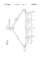
Referring to FIG. 1, a typical color printer includes a resetting apparatus 15, laser scanning units 16, developing apparatuses 17, a drying apparatus 18 and a transferring apparatus 20 are arranged adjacent to a circulation path of a photosensitive belt 14 circulated by three rollers 11, 12 and 13 and spaced apart from each other by a predetermined distance.
In the process of printing, the laser scanning unit 16 scans light beams over a predetermined region of the photosensitive belt 14 circulating via the resetting apparatus 15. An electrostatic latent image is formed on the photosensitive belt 14 by the scanned light, and the electrostatic latent image is developed by a developer supplied from a developing apparatus 17. A color image is formed on the photosensitive belt 14 by the laser scanning units 16 scanning light beams of various colors and the developing apparatuses 17 developing the scanned image by the developer corresponding to the light beam. The color image formed on the photosensitive belt 14 by a developer is primarily transferred to a transfer roller 21, which rotates partially in contact with the photosensitive belt 14, via the drying apparatus 18. Then, the image formed on the transfer roller 21 is secondarily transferred onto a sheet of paper 23 proceeding forward according to rotation of the transfer roller 21 and a pressure roller 22 which press against each other with the paper 23 therebetween.
Meanwhile, a power switch (not shown) with which a user can interrupt or connect an external commercialized alternating current (AC) power supply with respect to the inside of the printer is typically provided outside the main body. When the power switch is turned off due to a user's mistake or carelessness during a printing operation of the printer, the printing operation is interrupted due to interruption of the power supply. If the power supply is interrupted during the printing operation, the developing material which is not yet transferred to the paper sheet 23 remains on the photosensitive belt 14 or the transfer roller 21, thereby causing contamination of elements. Also, if the contamination is not instantly removed, the printing quality may be severely damaged.
SUMMARY OF THE INVENTION
To solve the above problem, it is an objective of the present invention to provide a power supply controlling apparatus for a printer continuously supplying power required to complete the remaining printing even though a power supply switch is turned off during printing.
Accordingly, to achieve the above objective, a power supply control apparatus according to the present invention comprises: a first rectifier rectifying current supplied by an external alternating current (AC) power supply; a switching unit capable of connecting and disconnecting a discharge path of current charged in the first rectifier; a switching controlling unit controlling the connection and disconnection of the switching unit; a first switch operating unit for outputting a first control signal to switch on and off a power supply line connected to the switching controlling unit according to the on and off state of the first switch; a second switch capable of connecting/separating the power supply line connected to the switching controlling unit; a system controlling unit for controlling overall operations of the printer, receiving the first control signal to determine the on and off state of the first switch, and determining the printing state to output a second control signal allowing the second switch to be switched on and off; and a second switch controlling unit receiving the first and second control signals to switch the second switch on and off.
Preferably, the apparatus further includes a transformer having at least one second winding inductively coupled to a first winding installed in the discharge path; a second rectifier rectifying electric energy induced in the second winding to generate a voltage required for the printer; and a third rectifier transforming power supplied by the external AC power supply to produce a direct current (DC) voltage for the switching controlling unit.
It is also preferable that the first switch operating unit comprises: a comparator comparing signals of first and second input ends to output the compared result as the first control signal; and a first switch operating signal generator supplying a first reference voltage signal to the first input end, and outputting one of a second voltage signal having a level higher than the first reference voltage level and a third voltage signal having a level lower than the first reference voltage level, to the second input end according to the on and off operations of the first switch. Also, the first switch is installed on an outer circumference or surface of the printer so as to be accessible for use by a user.
BRIEF DESCRIPTION OF THE DRAWINGS
The above objective and advantages of the present invention will become more apparent by describing in detail a preferred embodiment thereof with reference to the attached drawings in which:
FIG. 1 is a sectional view of a typical printer; and
FIG. 2 is a circuit diagram of a power supply controlling apparatus for a printer according to a preferred embodiment of the present invention.
DESCRIPTION OF THE PREFERRED EMBODIMENT
Referring to FIG. 2, a power supply controlling apparatus for a printer includes a first rectifier 30 for rectifying the voltage from an external alternating current (AC) power supply 35. A bridge diode 31 provided in the first rectifier 30 rectifies the voltage and current from the external AC power supply 35 (e.g., a common AC power supply such as 110VAC or 220VAC) and capacitors 32 are charged by current flowing through the bridge diode 31. Resistors R1 and R2 are for discharge.
A first winding 41 of a transforming unit 40 is connected between the first rectifier 30 and a switching unit 45, and is inductively coupled with a second winding 42 according to a predetermined winding ratio.
A switching device 46 such as a bipolar or field effect transistor is provided in the switching unit 45 to connect and disconnect a current discharge path of the first winding 41. Alternatively, the switching device 46 may be connected between the first rectifier 30 and the first winding 41 to connect and disconnect the current path of the first winding 41.
The transformer circuit 40 inductively transforms energy supplied from the first rectifier 30 to the first winding 41 in the second winding 42 according to switching of switching unit 45. The switching unit 45 may be constructed to employ various power transforming methods (e.g., pushpull and half-bridge).
Energy induced in the second winding 42 of the transformer 40 charges a capacitor via a diode of a second rectifier 43. As a result, the second rectifier 43 generates a voltage supply required by the printer.
The number of couplings and the winding ratio of the second winding 42 with respect to the first winding 41 are determined such that power is supplied to elements of a printer having a printer engine 48 including a resetting apparatus, laser scanning apparatuses, a transferring apparatus (see FIG. 1) and a system controlling unit 100. A base power supply of the second rectifier 43 supplied to the printer is categorized into power supplies of 24V and 12V for driving motors, and 5V for processing a logic signal.
A switching controlling unit 50 controlling the switching unit 45, controls on/off operation of the switching device 46 to maintain the amount of the power transferred to the second winding 42 such that the voltage level required by the system is maintained go within a predetermined range of the second rectifier 43. The switching controlling unit 50 may receive a voltage signal from the second rectifier 43 for controlling the on/off period of the switching device 46.
In the power transforming circuit, supply of the driving power to the switching controlling unit 50 is controlled based on the fact that the power of the first winding 41 is not transmitted to the second winding 42 when the switching device 46 of the switching unit 45 is switched off. Thus, the power supply to the printer is thereby controlled. The method of supplying and interrupting power to and from the printer by the power switch installed on a supply line between the external AC power supply 35 and the first rectifier 30 is, therefore, different from the conventional method.
A direct current (DC) voltage supply to be supplied to the switching controlling unit 50 is generated by a third rectifier 60. The energy delivered across a capacitor 64 constitutes the DC voltage supply. The typical switching controlling unit 50 requires a voltage of approximately 20V. Thus, the third rectifier 60 includes a transformer 62 for transforming the relatively high AC voltage of the external AC power supply 35 to a relatively low AC voltage according to a selected winding ratio, a bridge diode 61 for rectifying current induced in the secondary coil of the transformer 62, and the capacitor 64 charged by the rectified current.
The input line of the third rectifier 60 may be directly connected to the external AC power supply 35. Alternatively, the third rectifier 60 may also be constructed to obtain a required voltage by stepping down the output voltage of the first rectifier 30. The energy delivered to the third rectifier 60 is used to supply the power to the switching controlling unit 50, and drive a first switch operating unit, a second switch controlling unit 90 and a second switch 70. The first switch operating unit includes a first switch operating signal generator 80 and a comparator 85.
In the first switch operating signal generator 80, a voltage drop level due to the passage of current through a resistor R5 having one end connected to a ground line is output to a first input end 81 of the comparator 85 as a first reference voltage signal. Resistor R5 is serially connected with resistors R3 and R4 in parallel with the capacitor 64 which delivers the DC voltage supply. Also, if a first switch 83 is turned off, the voltage level across the capacitor 64 is output to a second input end 82 of the comparator 85 as a second voltage signal. On the other hand, if the first switch 83 is turned on, two resistors R6 and R7 and the first switch 83 are serially arranged in parallel with the capacitor 64 such that a voltage drop level due to passage of current through the resistance device R7 is output to the second input end 82 of the comparator 85 as a third voltage signal.
When the first switch 83 is turned on, the resistance values of the resistors R3 through R7 are determined such that the third voltage signal output to the second input end 82 has a voltage level lower than the first reference voltage signal.
The first switch 83 is installed on an outer circumference or surface of the printer such that it is accessible to be manually operated by a user similar to a conventional power supply switch.
The comparator 85 compares the first reference voltage signal input through the first input end 81 with the third voltage input signal having a different value according to the on/off state of the first switch 83 through the second input end 82.
The second switch 70 consisting of a relay, for example, is installed on a power supply line 65 and includes a switch member 71 capable of connecting or disconnecting both ends of the power supply line 65 according to change of a magnetic force, and a coil unit 72 causing the change of the magnetic force.
The second switch controlling unit 90 includes a switch device such as transistor 94 which is turned on according to signals from the comparator 85 and another switching device such as transistor 91 having one end connected to the coil unit 72 and the other end connected to the transistor 94, to connect and disconnect the current path from the DC voltage supply to the coil unit 72. The transistor 91 is switched on by first and second control signals output by the comparator 85 and the system controller 100, respectively. That is, if the first control signal output from the comparator 85 is a high level signal, a light emitting device 92 does not operate, so that a light receiving device 93 is open when receiving a light emitting signal to turn on the transistor 91, and, thus, a current passing path of the coil unit 72 is opened. If the first control signal of the comparator 85 is a low level signal, the light emitting device 92 and the light receiving device 93 are turned on, and the transistor 91 is switched on. Subsequently, current passes through the coil unit 72 and the switch member 71 is turned on.
In addition, a switch device 95 connected through a detour path is switched on/off by the system controlling unit 100 to control the light emission of the light emitting device 92. Thus, if the first control signal output from the comparator 85 is a low level signal or the second control signal output from the system controlling unit 100 is a high level signal, the second switch controlling unit 90 drives the switch member 71 to turn on.
Meanwhile, the first control signal of the comparator 85 output to the system controlling unit 100 supplies information concerning the on/off state of the first switch 83 which is, in essence, the power supply switch for the printer. That is, if the output signal of the comparator 85 is a low level, the system controlling unit 100 determines that the first switch 83 is in the "on" state, and if it is a high level, the system controlling unit 100 determines that the first switch 83 is in the "off" state.
In operation, if the external AC supply 35 and the power supply controller are connected through a plug (not shown), power from the external AC supply 35 is supplied to the first and third rectifiers 30 and 60, irrespective of the on/off state of the first switch 83.
If the first switch 83 is turned on, a first reference voltage signal and a third voltage signal having a level lower than that of the first reference voltage signal are input to the first and second input ends (81 and 82) of the comparator 85. As a result, the comparator 85 outputs a low level output signal since the third voltage signal is lower than the first reference voltage. Accordingly, the light emitting device 92 emits light according to the low level output signal of the comparator 85. If the light emitting device 92 emits light, the light receiving device 93 is turned on which, in turn, causes the transistor 91 to be switched on. As transistor 91 conducts current, coil 72 is energized, thereby turning on the switch member 71. Accordingly, power from the third rectifier 60 is supplied to the switching controlling unit 50 via switch 71. When the switching controlling unit 50 to which power is supplied controls the on/off operation of the switching unit 45, the power is induced in the second winding 42 to supply the power required for the printer.
If the first switch 83 is turned off by a user, the third voltage signal becomes higher than the first reference voltage causing the comparator to output a high level signal. The transistor 94 is turned off by the high level output signal of the comparator 85 causing the light emitting device 92 to be turned off, and thus causes the switch member 71 to be turned off, thereby interrupting the supply of power to the switching controlling unit 50. When the power supply to the switching controlling unit 50 is interrupted, the controlling unit 50 cannot turn on the switching unit 45, and thus the supply of power required for the printer is interrupted. Here, the first switch 83 functions as a conventional power supply switch.
Meanwhile, the on/off operation of the first switch 83 is supervised by the system controlling unit 100 receiving an output signal of the comparator 85. Thus, when the first switch 83 is turned off by the user during printing, the system controlling unit 100 immediately outputs a turn-on signal allowing the light emitting device 92 to emit light, even though the output level of the comparator 85 is high. The light emitting device 92 continues to emit light due to the output of the system controlling unit 100, so that the switch member 71 is maintained in an activated state. Thus, power for printer engine driving can be supplied from the second rectifier 43 via the switching controlling unit 50.
After completion of the printing, the system controlling unit 100 outputs a second control signal of low level such that the light emitting device 92 is turned off, thereby causing the supply of power for the switching controlling unit 50 to be interrupted. As a result, the power supply from the second rectifier 43 to the printer is interrupted. At this time, operation of the system controlling unit 100 receiving power through the output end of the second rectifier 43 is stopped by the interruption of power together with the printer engine 48. Thus, the printer is completely inactivated in which the operation cannot resume until the first switch 83 is turned on.
As described above, according to the power supply controlling apparatus for a printer of the present invention, even though the first switch capable of controlling the supply and interruption of power to the printer is turned off during printing due to carelessness, the supply of power required to complete the remaining printing operation can be continued, to thereby suppress contamination of the device due to forcible interruption of operation.
While the present invention has been described and illustrated with reference to a preferred embodiment thereof, it is to be readily understood that the present invention is not limited to the embodiment, and various changes and modifications can be made therein without departing from the spirit and scope of the invention defined in the appended claims.

Claims (11)

What is claimed is:
1. A power supply controlling apparatus for a printer comprising:
a first rectifier rectifying current supplied by an external alternating current (AC) power supply;
a switching unit for connecting and disconnecting a discharge path of current rectified in the first rectifier;
a switching controlling unit controlling the connection and disconnection operation of the switching unit;
a power supply line connected to the switching controlling unit for supplying power to the switching control unit;
a first switch operating unit for outputting a first control signal used to effect on and off switching of a connection of the power supply line to the switching controlling unit according to an on/off state of a first switch;
a second switch for switching the connection of the power supply line to the switching controlling unit;
a system controlling unit for controlling overall operations of the printer, receiving the first control signal to determine the on and off state of the first switch, determining a printing state, and outputting a second control signal which permits the second switch to be switched on and off based on the determinations of the first switch state and the printing state; and
a second switch controlling unit receiving the first and second control signals to switch the second switch on and off.
2. The apparatus of claim 1, further comprising:
a transformer including at least one secondary winding inductively coupled with a first winding connected in the discharge path;
a second rectifier rectifying electric energy induced in the secondary winding to generate a voltage required for operation of the printer; and
a third rectifier transforming power supplied by the external AC power supply to produce a direct current voltage for powering the switching controlling unit.
3. The apparatus of claim 1, wherein the first switch operating unit comprises:
a comparator comparing signals of first and second input ends and outputting a compared result as the first control signal; and
a first switch operating signal generator supplying a first reference voltage signal to the first input end, and supplying one of a second voltage signal having a level higher than the first reference voltage level and a third voltage signal having a level lower than the first reference voltage level to the second input end according to the on/off state of the first switch.
4. The apparatus of claim 1, wherein the second switch comprises:
a switch member for connecting and interrupting the power supply line according to a change of a magnetic force; and
a coil unit generating the change of the magnetic force according to continuity and interruption of current depending on control of the second switch controlling unit.
5. The apparatus of claim 4, wherein the second switch controlling unit comprises a switch device connected to an end of the coil unit having another end connected to a direct current voltage source to control continuity and interruption of current in the coil unit, the switch device being switched on according to the first and second control signals.
6. The apparatus of claim 1, wherein the first switch is installed in an outer circumference of the printer to allow a user to select between of on and off states of the first switch.
7. The apparatus of claim 2, wherein the first switch operating unit comprises:
a comparator comparing signals of first and second input ends and outputting a compared result as the first control signal; and
a first switch operating signal generator supplying a first reference voltage signal to the first input end, and supplying one of a second voltage signal having a level higher than the first reference voltage level and a third voltage signal having a level lower than the first reference voltage level to the second input end according to the on/off state of the first switch.
8. The apparatus of claim 2, wherein the second switch comprises:
a switch member capable of connecting and interrupting the power supply line according to a change of a magnetic force; and
a coil unit generating the change of the magnetic force according to continuity and interruption of current depending on control of the second switch controlling unit.
9. The apparatus of claim 8, wherein the second switch controlling unit comprises a switch device connected to a end of the coil unit having another end connected to the direct current (DC) voltage source supplied by the third rectifier to control continuity and interruption of current of the coil unit, the switch device being switched on according to the first and second control signals.
10. The apparatus of claim 2, wherein the system controlling unit receives a voltage source supplied by the second rectifier as driving power.
11. The apparatus of claim 2, wherein the first switch is installed on an outer circumference of the printer to allow a user to select between on and off states of the first switch.
US09/129,217 1997-08-27 1998-08-05 Power supply controlling apparatus for printer Expired - Fee Related US5995397A (en)

Applications Claiming Priority (2)

Application Number Priority Date Filing Date Title
KR97-41631 1997-08-27
KR1019970041631A KR100219659B1 (en) 1997-08-27 1997-08-27 Power supply controlling device of printing device

Publications (1)

Publication Number Publication Date
US5995397A true US5995397A (en) 1999-11-30

Family

ID=19518916

Family Applications (1)

Application Number Title Priority Date Filing Date
US09/129,217 Expired - Fee Related US5995397A (en) 1997-08-27 1998-08-05 Power supply controlling apparatus for printer

Country Status (2)

Country Link
US (1) US5995397A (en)
KR (1) KR100219659B1 (en)

Cited By (20)

* Cited by examiner, † Cited by third party
Publication number Priority date Publication date Assignee Title
US6178299B1 (en) * 1998-08-07 2001-01-23 Samsung Electronics Co., Ltd. Method of controlling power supply to heat source of printer and apparatus therefor
US6408148B1 (en) * 1999-05-17 2002-06-18 Canon Kabushiki Kaisha Image processing apparatus, image recording apparatus, controlling method for these apparatuses, and power supply apparatus used therein
US20040017112A1 (en) * 2002-07-23 2004-01-29 Samsung Electronics Co., Ltd. Power supply controlling device of an electronic equipment
US20040125616A1 (en) * 2002-07-23 2004-07-01 Samsung Electronics Co., Ltd. Method and apparatus for controlling a power supply in an electronic machine using a host
US20040135834A1 (en) * 2003-01-13 2004-07-15 Gilbert Hugh E. Power control circuit for printers and other devices
US20040190312A1 (en) * 2003-03-24 2004-09-30 Yokogawa Electric Corporation Switching power supply
KR100470593B1 (en) * 2002-09-18 2005-03-10 삼성전자주식회사 Power supply controlling device of electronic equipment having key off function
US20060139390A1 (en) * 2004-12-29 2006-06-29 Oce-Technologies B.V. Temperature control system for a sheet support plate of a printer
EP1679572A1 (en) * 2004-12-29 2006-07-12 Océ-Technologies B.V. Temperature control system for a sheet support plate of a printer
US20070070387A1 (en) * 2005-09-27 2007-03-29 Sun-Jin Kim Image forming apparatus, additional apparatus connectable to image forming apparatus, image forming system, and control method thereof
US20090027929A1 (en) * 2007-07-27 2009-01-29 Samsung Electronics Co., Ltd. Power supply circuit of image display apparatus
US20100197485A1 (en) * 2008-07-31 2010-08-05 Celanese International Corporation Catalysts for making ethanol from acetic acid
US20110085817A1 (en) * 2007-06-11 2011-04-14 Samsung Electronics Co., Ltd Power supply device and image forming apparatus having the same
US20110187192A1 (en) * 2005-10-28 2011-08-04 Samsung Electronics Co., Ltd. Switching mode power supply and a method of operating the power supply in a power save mode
US20130100712A1 (en) * 2011-10-20 2013-04-25 Canon Kabushiki Kaisha Power source device and image forming apparatus
US8680317B2 (en) 2008-07-31 2014-03-25 Celanese International Corporation Processes for making ethyl acetate from acetic acid
US20140122905A1 (en) * 2012-10-30 2014-05-01 Inventec Corporation Power start-up device and power start-up method
US20150310320A1 (en) * 2014-04-25 2015-10-29 Oki Data Corporation Printer
US9213504B2 (en) 2013-04-17 2015-12-15 Casio Computer Co., Ltd. Printing apparatus, power supply control apparatus, power supply control method, and storage medium
US9397553B2 (en) 2011-11-07 2016-07-19 Samsung Electronics Co., Ltd. Switching mode power supply, apparatus and method of supplying power by using the same, and image forming apparatus therefor

Citations (4)

* Cited by examiner, † Cited by third party
Publication number Priority date Publication date Assignee Title
US5132891A (en) * 1990-08-03 1992-07-21 International Business Machines Corporation Power supply apparatus
US5497311A (en) * 1994-03-22 1996-03-05 Yokogawa Electric Corporation Switching power source of the voltage resonance type
US5499184A (en) * 1994-01-28 1996-03-12 Compaq Computer Corp. Power switch circuitry for electrically isolating the power switch from a power supply
US5546161A (en) * 1991-04-17 1996-08-13 Canon Kabushiki Kaisha Image forming system having main power source

Patent Citations (4)

* Cited by examiner, † Cited by third party
Publication number Priority date Publication date Assignee Title
US5132891A (en) * 1990-08-03 1992-07-21 International Business Machines Corporation Power supply apparatus
US5546161A (en) * 1991-04-17 1996-08-13 Canon Kabushiki Kaisha Image forming system having main power source
US5499184A (en) * 1994-01-28 1996-03-12 Compaq Computer Corp. Power switch circuitry for electrically isolating the power switch from a power supply
US5497311A (en) * 1994-03-22 1996-03-05 Yokogawa Electric Corporation Switching power source of the voltage resonance type

Cited By (29)

* Cited by examiner, † Cited by third party
Publication number Priority date Publication date Assignee Title
US6178299B1 (en) * 1998-08-07 2001-01-23 Samsung Electronics Co., Ltd. Method of controlling power supply to heat source of printer and apparatus therefor
US6408148B1 (en) * 1999-05-17 2002-06-18 Canon Kabushiki Kaisha Image processing apparatus, image recording apparatus, controlling method for these apparatuses, and power supply apparatus used therein
US20040017112A1 (en) * 2002-07-23 2004-01-29 Samsung Electronics Co., Ltd. Power supply controlling device of an electronic equipment
US20040125616A1 (en) * 2002-07-23 2004-07-01 Samsung Electronics Co., Ltd. Method and apparatus for controlling a power supply in an electronic machine using a host
US7002814B2 (en) * 2002-07-23 2006-02-21 Samsung Electronics Co., Ltd. Power supply controlling device of an electronic equipment
KR100470593B1 (en) * 2002-09-18 2005-03-10 삼성전자주식회사 Power supply controlling device of electronic equipment having key off function
US20040135834A1 (en) * 2003-01-13 2004-07-15 Gilbert Hugh E. Power control circuit for printers and other devices
US6908164B2 (en) 2003-01-13 2005-06-21 Lexmark International, Inc. Power control circuit for printers and other devices
US20040190312A1 (en) * 2003-03-24 2004-09-30 Yokogawa Electric Corporation Switching power supply
US20060139390A1 (en) * 2004-12-29 2006-06-29 Oce-Technologies B.V. Temperature control system for a sheet support plate of a printer
EP1679572A1 (en) * 2004-12-29 2006-07-12 Océ-Technologies B.V. Temperature control system for a sheet support plate of a printer
US7510276B2 (en) 2004-12-29 2009-03-31 Oce-Technologies B.V. Temperature control system for a sheet support plate of a printer
US20070070387A1 (en) * 2005-09-27 2007-03-29 Sun-Jin Kim Image forming apparatus, additional apparatus connectable to image forming apparatus, image forming system, and control method thereof
US8223510B2 (en) * 2005-10-28 2012-07-17 Samsung Electronics Co., Ltd. Switching mode power supply and a method of operating the power supply in a power save mode
US20110187192A1 (en) * 2005-10-28 2011-08-04 Samsung Electronics Co., Ltd. Switching mode power supply and a method of operating the power supply in a power save mode
US20110085817A1 (en) * 2007-06-11 2011-04-14 Samsung Electronics Co., Ltd Power supply device and image forming apparatus having the same
US8218995B2 (en) * 2007-06-11 2012-07-10 Samsung Electronics Co., Ltd. Power supply device and image forming apparatus having the same
US20090027929A1 (en) * 2007-07-27 2009-01-29 Samsung Electronics Co., Ltd. Power supply circuit of image display apparatus
US20100197485A1 (en) * 2008-07-31 2010-08-05 Celanese International Corporation Catalysts for making ethanol from acetic acid
US8501652B2 (en) 2008-07-31 2013-08-06 Celanese International Corporation Catalysts for making ethanol from acetic acid
US8680317B2 (en) 2008-07-31 2014-03-25 Celanese International Corporation Processes for making ethyl acetate from acetic acid
US9040443B2 (en) 2008-07-31 2015-05-26 Celanese International Corporation Catalysts for making ethanol from acetic acid
US20130100712A1 (en) * 2011-10-20 2013-04-25 Canon Kabushiki Kaisha Power source device and image forming apparatus
US9154043B2 (en) * 2011-10-20 2015-10-06 Canon Kabushiki Kaisha Power source device and image forming apparatus
US9397553B2 (en) 2011-11-07 2016-07-19 Samsung Electronics Co., Ltd. Switching mode power supply, apparatus and method of supplying power by using the same, and image forming apparatus therefor
US20140122905A1 (en) * 2012-10-30 2014-05-01 Inventec Corporation Power start-up device and power start-up method
US9213504B2 (en) 2013-04-17 2015-12-15 Casio Computer Co., Ltd. Printing apparatus, power supply control apparatus, power supply control method, and storage medium
US20150310320A1 (en) * 2014-04-25 2015-10-29 Oki Data Corporation Printer
US9420138B2 (en) * 2014-04-25 2016-08-16 Oki Data Corporation Printer

Also Published As

Publication number Publication date
KR19990018455A (en) 1999-03-15
KR100219659B1 (en) 1999-09-01

Similar Documents

Publication Publication Date Title
US5995397A (en) Power supply controlling apparatus for printer
US8059983B2 (en) Phase detecting device, phase control device including the phase detecting device, and fuser control device including the phase control device
US5376998A (en) Image formation apparatus including a plurality of development unit selectively driven by a common power source
US9122224B2 (en) Image forming apparatus and power supply device
JP7040884B2 (en) Power supply, image forming device and control method
JP2008172914A (en) Power supply device and image forming device
JP2007049832A (en) Power supply unit and image forming device
KR100461347B1 (en) Image fixing appatatus being used 110V/220V and printer thereof
US6236819B1 (en) Printer capable of returning to a reset state even if external power is interrupted
JP4341945B2 (en) Zero-cross detection method, power supply device, and image forming apparatus
JPH11143341A (en) Image forming device
JPH0993910A (en) Image forming apparatus
JP2001245470A (en) Power source device
US20220294356A1 (en) Power supply apparatus with smoothing capacitor and image forming apparatus
JP6635681B2 (en) Image forming device
JP3474041B2 (en) Image forming device
JP2000293072A (en) Image forming device
JPH11125979A (en) High-voltage power source circuit for electrophotographic printer, and electrophotographic printer and copying machine using the same
JPH07219363A (en) Fault detector of fixing device for image recording and image recorder
JPH10105254A (en) Heater controller and image forming device
JPH0618365Y2 (en) Pin corotron deterioration determination circuit
JP4863092B2 (en) Image forming apparatus
JP2014155370A (en) Power supply device and image forming apparatus
JP2003244951A (en) Apparatus and method for controlling power
JPH01103447A (en) Image forming device

Legal Events

Date Code Title Description
AS Assignment

Owner name: SAMSUNG ELECTRONICS CO., LTD., KOREA, REPUBLIC OF

Free format text: ASSIGNMENT OF ASSIGNORS INTEREST;ASSIGNOR:KIM, MIN-SEON;REEL/FRAME:009374/0463

Effective date: 19980803

FEPP Fee payment procedure

Free format text: PAYOR NUMBER ASSIGNED (ORIGINAL EVENT CODE: ASPN); ENTITY STATUS OF PATENT OWNER: LARGE ENTITY

FPAY Fee payment

Year of fee payment: 4

FPAY Fee payment

Year of fee payment: 8

REMI Maintenance fee reminder mailed
LAPS Lapse for failure to pay maintenance fees
STCH Information on status: patent discontinuation

Free format text: PATENT EXPIRED DUE TO NONPAYMENT OF MAINTENANCE FEES UNDER 37 CFR 1.362

FP Lapsed due to failure to pay maintenance fee

Effective date: 20111130