US6002822A - Article comprising an optional waveguide tap - Google Patents
Article comprising an optional waveguide tap Download PDFInfo
- Publication number
- US6002822A US6002822A US09/088,512 US8851298A US6002822A US 6002822 A US6002822 A US 6002822A US 8851298 A US8851298 A US 8851298A US 6002822 A US6002822 A US 6002822A
- Authority
- US
- United States
- Prior art keywords
- light
- wavelength
- optical
- grating
- waveguide
- Prior art date
- Legal status (The legal status is an assumption and is not a legal conclusion. Google has not performed a legal analysis and makes no representation as to the accuracy of the status listed.)
- Expired - Fee Related
Links
- 230000003287 optical effect Effects 0.000 claims abstract description 63
- 230000008878 coupling Effects 0.000 claims abstract description 43
- 238000010168 coupling process Methods 0.000 claims abstract description 43
- 238000005859 coupling reaction Methods 0.000 claims abstract description 43
- 230000005855 radiation Effects 0.000 claims abstract description 32
- 238000005253 cladding Methods 0.000 claims abstract description 25
- 239000000835 fiber Substances 0.000 claims description 68
- 239000013307 optical fiber Substances 0.000 claims description 23
- 238000004891 communication Methods 0.000 abstract description 15
- 239000011521 glass Substances 0.000 abstract description 6
- 238000012423 maintenance Methods 0.000 abstract 2
- VYPSYNLAJGMNEJ-UHFFFAOYSA-N Silicium dioxide Chemical compound O=[Si]=O VYPSYNLAJGMNEJ-UHFFFAOYSA-N 0.000 description 20
- 239000004593 Epoxy Substances 0.000 description 13
- 239000000377 silicon dioxide Substances 0.000 description 10
- 230000005540 biological transmission Effects 0.000 description 8
- 239000010410 layer Substances 0.000 description 8
- 230000003595 spectral effect Effects 0.000 description 7
- 239000006185 dispersion Substances 0.000 description 6
- 230000010287 polarization Effects 0.000 description 6
- 238000001514 detection method Methods 0.000 description 5
- 238000001228 spectrum Methods 0.000 description 5
- 230000003247 decreasing effect Effects 0.000 description 4
- 230000008859 change Effects 0.000 description 3
- 230000004044 response Effects 0.000 description 3
- 238000000926 separation method Methods 0.000 description 3
- YZCKVEUIGOORGS-OUBTZVSYSA-N Deuterium Chemical compound [2H] YZCKVEUIGOORGS-OUBTZVSYSA-N 0.000 description 2
- 229910000530 Gallium indium arsenide Inorganic materials 0.000 description 2
- 238000000137 annealing Methods 0.000 description 2
- 239000011248 coating agent Substances 0.000 description 2
- 238000000576 coating method Methods 0.000 description 2
- 229910052681 coesite Inorganic materials 0.000 description 2
- 229910052906 cristobalite Inorganic materials 0.000 description 2
- 230000001419 dependent effect Effects 0.000 description 2
- 229910052805 deuterium Inorganic materials 0.000 description 2
- 238000004519 manufacturing process Methods 0.000 description 2
- 229920000728 polyester Polymers 0.000 description 2
- 229920005594 polymer fiber Polymers 0.000 description 2
- 230000000644 propagated effect Effects 0.000 description 2
- 230000001902 propagating effect Effects 0.000 description 2
- 230000007480 spreading Effects 0.000 description 2
- 238000003892 spreading Methods 0.000 description 2
- 229910052682 stishovite Inorganic materials 0.000 description 2
- 238000000411 transmission spectrum Methods 0.000 description 2
- 229910052905 tridymite Inorganic materials 0.000 description 2
- 230000006978 adaptation Effects 0.000 description 1
- 230000015556 catabolic process Effects 0.000 description 1
- 238000006243 chemical reaction Methods 0.000 description 1
- 230000006835 compression Effects 0.000 description 1
- 238000007906 compression Methods 0.000 description 1
- 239000012792 core layer Substances 0.000 description 1
- 230000007423 decrease Effects 0.000 description 1
- 238000006731 degradation reaction Methods 0.000 description 1
- 230000000694 effects Effects 0.000 description 1
- 230000005670 electromagnetic radiation Effects 0.000 description 1
- 230000008030 elimination Effects 0.000 description 1
- 238000003379 elimination reaction Methods 0.000 description 1
- 238000005516 engineering process Methods 0.000 description 1
- 239000000284 extract Substances 0.000 description 1
- 239000000463 material Substances 0.000 description 1
- 238000000034 method Methods 0.000 description 1
- 238000000206 photolithography Methods 0.000 description 1
- 238000010079 rubber tapping Methods 0.000 description 1
- 230000035945 sensitivity Effects 0.000 description 1
- 239000000758 substrate Substances 0.000 description 1
- 238000011144 upstream manufacturing Methods 0.000 description 1
Images


Classifications
-
- G—PHYSICS
- G02—OPTICS
- G02B—OPTICAL ELEMENTS, SYSTEMS OR APPARATUS
- G02B6/00—Light guides; Structural details of arrangements comprising light guides and other optical elements, e.g. couplings
- G02B6/24—Coupling light guides
- G02B6/26—Optical coupling means
- G02B6/28—Optical coupling means having data bus means, i.e. plural waveguides interconnected and providing an inherently bidirectional system by mixing and splitting signals
- G02B6/293—Optical coupling means having data bus means, i.e. plural waveguides interconnected and providing an inherently bidirectional system by mixing and splitting signals with wavelength selective means
- G02B6/29304—Optical coupling means having data bus means, i.e. plural waveguides interconnected and providing an inherently bidirectional system by mixing and splitting signals with wavelength selective means operating by diffraction, e.g. grating
- G02B6/29316—Light guides comprising a diffractive element, e.g. grating in or on the light guide such that diffracted light is confined in the light guide
- G02B6/29323—Coupling to or out of the diffractive element through the lateral surface of the light guide
-
- G—PHYSICS
- G01—MEASURING; TESTING
- G01J—MEASUREMENT OF INTENSITY, VELOCITY, SPECTRAL CONTENT, POLARISATION, PHASE OR PULSE CHARACTERISTICS OF INFRARED, VISIBLE OR ULTRAVIOLET LIGHT; COLORIMETRY; RADIATION PYROMETRY
- G01J3/00—Spectrometry; Spectrophotometry; Monochromators; Measuring colours
- G01J3/12—Generating the spectrum; Monochromators
- G01J3/18—Generating the spectrum; Monochromators using diffraction elements, e.g. grating
- G01J3/1895—Generating the spectrum; Monochromators using diffraction elements, e.g. grating using fiber Bragg gratings or gratings integrated in a waveguide
-
- G—PHYSICS
- G02—OPTICS
- G02B—OPTICAL ELEMENTS, SYSTEMS OR APPARATUS
- G02B6/00—Light guides; Structural details of arrangements comprising light guides and other optical elements, e.g. couplings
- G02B6/02—Optical fibres with cladding with or without a coating
- G02B6/02057—Optical fibres with cladding with or without a coating comprising gratings
- G02B6/02076—Refractive index modulation gratings, e.g. Bragg gratings
- G02B6/0208—Refractive index modulation gratings, e.g. Bragg gratings characterised by their structure, wavelength response
- G02B6/02085—Refractive index modulation gratings, e.g. Bragg gratings characterised by their structure, wavelength response characterised by the grating profile, e.g. chirped, apodised, tilted, helical
-
- G—PHYSICS
- G02—OPTICS
- G02B—OPTICAL ELEMENTS, SYSTEMS OR APPARATUS
- G02B6/00—Light guides; Structural details of arrangements comprising light guides and other optical elements, e.g. couplings
- G02B6/24—Coupling light guides
- G02B6/26—Optical coupling means
- G02B6/28—Optical coupling means having data bus means, i.e. plural waveguides interconnected and providing an inherently bidirectional system by mixing and splitting signals
- G02B6/293—Optical coupling means having data bus means, i.e. plural waveguides interconnected and providing an inherently bidirectional system by mixing and splitting signals with wavelength selective means
- G02B6/29346—Optical coupling means having data bus means, i.e. plural waveguides interconnected and providing an inherently bidirectional system by mixing and splitting signals with wavelength selective means operating by wave or beam interference
- G02B6/29358—Multiple beam interferometer external to a light guide, e.g. Fabry-Pérot, etalon, VIPA plate, OTDL plate, continuous interferometer, parallel plate resonator
- G02B6/29359—Cavity formed by light guide ends, e.g. fibre Fabry Pérot [FFP]
-
- G—PHYSICS
- G02—OPTICS
- G02B—OPTICAL ELEMENTS, SYSTEMS OR APPARATUS
- G02B6/00—Light guides; Structural details of arrangements comprising light guides and other optical elements, e.g. couplings
- G02B6/24—Coupling light guides
- G02B6/26—Optical coupling means
- G02B6/34—Optical coupling means utilising prism or grating
-
- G—PHYSICS
- G02—OPTICS
- G02B—OPTICAL ELEMENTS, SYSTEMS OR APPARATUS
- G02B6/00—Light guides; Structural details of arrangements comprising light guides and other optical elements, e.g. couplings
- G02B6/24—Coupling light guides
- G02B6/42—Coupling light guides with opto-electronic elements
- G02B6/4201—Packages, e.g. shape, construction, internal or external details
- G02B6/4204—Packages, e.g. shape, construction, internal or external details the coupling comprising intermediate optical elements, e.g. lenses, holograms
- G02B6/4215—Packages, e.g. shape, construction, internal or external details the coupling comprising intermediate optical elements, e.g. lenses, holograms the intermediate optical elements being wavelength selective optical elements, e.g. variable wavelength optical modules or wavelength lockers
-
- G—PHYSICS
- G02—OPTICS
- G02B—OPTICAL ELEMENTS, SYSTEMS OR APPARATUS
- G02B6/00—Light guides; Structural details of arrangements comprising light guides and other optical elements, e.g. couplings
- G02B6/24—Coupling light guides
- G02B6/42—Coupling light guides with opto-electronic elements
- G02B6/4201—Packages, e.g. shape, construction, internal or external details
- G02B6/4287—Optical modules with tapping or launching means through the surface of the waveguide
- G02B6/4291—Optical modules with tapping or launching means through the surface of the waveguide by accessing the evanescent field of the light guide
-
- G—PHYSICS
- G02—OPTICS
- G02B—OPTICAL ELEMENTS, SYSTEMS OR APPARATUS
- G02B6/00—Light guides; Structural details of arrangements comprising light guides and other optical elements, e.g. couplings
- G02B6/02—Optical fibres with cladding with or without a coating
- G02B6/02057—Optical fibres with cladding with or without a coating comprising gratings
- G02B6/02076—Refractive index modulation gratings, e.g. Bragg gratings
- G02B6/02123—Refractive index modulation gratings, e.g. Bragg gratings characterised by the method of manufacture of the grating
- G02B6/02133—Refractive index modulation gratings, e.g. Bragg gratings characterised by the method of manufacture of the grating using beam interference
- G02B6/02138—Refractive index modulation gratings, e.g. Bragg gratings characterised by the method of manufacture of the grating using beam interference based on illuminating a phase mask
-
- G—PHYSICS
- G02—OPTICS
- G02B—OPTICAL ELEMENTS, SYSTEMS OR APPARATUS
- G02B6/00—Light guides; Structural details of arrangements comprising light guides and other optical elements, e.g. couplings
- G02B6/24—Coupling light guides
- G02B6/42—Coupling light guides with opto-electronic elements
- G02B6/4201—Packages, e.g. shape, construction, internal or external details
- G02B6/4274—Electrical aspects
Definitions
- This invention pertains to wavelength-selective means for coupling light from an optical fiber, and to articles (e.g., an optical amplifier) or systems (e.g., an optical fiber communication system; collectively “articles”) that comprise such means.
- articles e.g., an optical amplifier
- systems e.g., an optical fiber communication system; collectively “articles”
- wavelength-selective means for tapping electromagnetic radiation to be referred to herein as "light”, regardless of wavelength
- light could be advantageously used in a variety of functions, e.g., as a wavelength monitor, channel monitor, demultiplexer, amplifier monitor, or in a feedback loop with an optical amplifier.
- U.S. Pat. No. 5,061,032 to G. Meltz et al. discloses an optical fiber tap that comprises a blazed, chirped refractive index grating selected to redirect light guided in the fiber such that it comes to a focus at a point outside of the fiber.
- the patent also discloses that ". . . the angle of the external path that results in the constructive interference is peculiar to the respective central wavelength ⁇ ".
- the tap of the '032 patent has some shortcomings. For instance, due to the relatively large (exemplarily ⁇ 22°) blaze angle that is required to achieve the desired redirection of the light guided in the fiber core to light in space outside of the fiber, the arrangement is subject to undesirable polarization effects, i.e., the fraction of light that is redirected by the grating depends on the polarization of the incident guided light. Whereas for low blaze angles ( ⁇ 10°) the polarization dependent difference in the amount of redirected light is at most about 0.54 dB, this difference increases rapidly with increasing blaze angle, being about 2.86 dB and about 6.02 dB for blaze angles of 22° and 30°, respectively.
- guided modes we mean herein the propagating modes in the waveguide.
- the guided mode in a single mode conventional optical fiber is the LP 01 mode.
- cladding modes or “bound cladding modes” we mean herein optical modes of the waveguide structure that have an effective refractive index less than the refractive index of the cladding material of the waveguide. These modes are bound, in the sense that the optical power in these modes is always localized around the waveguide, and is not spreading out in a direction orthogonal to the propagation direction.
- Radiation modes we mean herein optical modes that are not completely localized to the waveguide structure. Radiation modes spread away from the waveguide structure, such that at some point along the length of the waveguide there is an arbitrarily small amount of optical power located in the waveguide structure.
- non-guided mode we mean herein a mode other than a guided mode, e.g., a cladding mode or a radiation mode.
- a refractive index grating herein is "blazed" if the plane of the index perturbations in the waveguide is not perpendicular to the propagation direction of the guided mode or modes.
- an article e.g., an optical waveguide communication system
- an optical waveguide having a refractive index grating and coupling means selected such that at least a portion of the light is transferred from a guided mode into a radiation mode and is available for utilization by utilization means (e.g., a detector) outside of the waveguide and the coupling means.
- utilization means e.g., a detector
- the invention is embodied in an article that comprises an optical waveguide for guiding light of wavelength ⁇ i in at least one guided mode.
- the optical waveguide comprises a chirped and blazed refractive index grating selected such that at least a portion of the light in the guided mode is transferred into a non-guided mode.
- the article further comprises utilization means for utilizing the light in the non-guided mode.
- the article further comprises coupling means that are in optical cooperation with the waveguide such that said non-guided mode is a radiation mode.
- the grating has a blaze angle ⁇ selected such that, in an otherwise identical comparison article that does not comprise said coupling means, the non-guided mode is a cladding mode.
- the grating furthermore has a chirp selected such that the light of wavelength ⁇ i in the radiation mode is substantially brought to a focus in at least one dimension at a predetermined location outside said coupling means.
- the presence of the coupling means changes the waveguide properties in the vicinity of the grating such that the grating directs the light into a radiation mode or modes, rather than into a cladding mode or modes. This is typically accomplished by elimination of some or all of the cladding modes in the region of the index grating by physical means (designated the “coupling means") that will be described in detail below.
- a waveguide tap according to the invention i.e., a dispersive waveguide tap or DWT
- a single wavelength optical waveguide system e.g., to monitor the operating wavelength
- such a tap will advantageously be used in a multiwavelength system, e.g., in a wavelength division multiplexed (WDM) optical fiber communication system.
- WDM wavelength division multiplexed
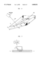
- FIG. 1 schematically depicts an exemplary optical communication system according to the invention
- FIG. 2 shows schematically a relevant portion of an exemplary system including a blazed and chirped grating according to the invention
- FIG. 3 shows an exemplary transmission spectrum
- FIGS. 4 and 5 illustrate spatial dispersion of a DWT according to the invention
- FIG. 6 schematically depicts relevant features of an exemplary DWT according to the invention, the tap embodied in planar waveguide technology
- FIG. 7 schematically depicts a further embodiment of a DWT according to the invention.
- FIG. 8 schematically depicts a relevant portion of an exemplary optical communication system according to the invention.
- FIGS. 9-11 schematically depict exemplary communication systems that utilize DWTs
- FIG. 12 shows the bandwidth response of an exemplary DWT with chirped grating, without lens
- FIGS. 13 and 15 show exemplary embodiments of DWTs without chirped grating, with lens.
- FIG. 14 shows the bandwidth response of an exemplary DWT without chirped grating, with lens.
- FIG. 1 schematically depicts an exemplary optical fiber communication system 10 according to the invention.
- Transmitter 11 provides signal radiation 16, exemplarily including light of wavelength ⁇ i .
- the signal radiation is coupled into conventional optical fiber 12 (typically a single mode fiber) in known fashion, and propagates in the fiber towards receiver 13.
- grating At an intermediate location in the fiber is provided blazed and chirped refractive index Bragg grating ("grating") 14.
- the grating is selected to direct, in optical co-operation with coupling means 15, guided mode light of a predetermined wavelength range (e.g., including ⁇ i ) into a radiation mode or modes.
- a predetermined wavelength range e.g., including ⁇ i
- light in LP 01 the fundamental guided mode
- the coupling means in co-operation with the fiber, not only ensure guided mode ⁇ radiation mode conversion but also allow spatial dispersion, such that light of wavelength ⁇ i is substantially brought to a focus at a predetermined point outside of the coupling means (and not located at the waveguide boundary), and light of wavelength ⁇ j ⁇ i is substantially brought to a focus in at least one dimension at a different point.
- numeral 18 refers to light of wavelength ⁇ i that is being brought to a focus at point 17.
- Utilization means 19 are positioned at or near the focal point.
- the grating is selected such that, in the absence of the coupling means, the grating directs radiation from a guided mode (exemplarily LP 01 ) into a cladding mode (or modes) of the waveguide.
- a guided mode exemplarily LP 01
- a cladding mode or modes
- FIG. 2 schematically shows an exemplary fiber tap according to the invention.
- Fiber 12 comprises a core 20 and a cladding 21.
- Grating 14 is formed in the core in conventional fashion.
- the fiber was a conventional silica-based single mode fiber, and a grating was written into the fiber using a phase mask.
- the grating had a 9° tilt (blaze), a period ⁇ (z) ranging linearly from 547.1 nm to 548.9 nm, and a Gaussian profile, with full width at half maximum (FWHM) of about 5 mm, corresponding to a linear chirp of about -3.6 nm/cm. Note that a negative chirp corresponds to decreasing grating period in the downstream direction.
- FWHM full width at half maximum
- Numeral 22 refers to an index matching medium, e.g., Cargill Oil, with refractive index chosen to be at or slightly above the refractive index of silica.
- an index matching medium e.g., Cargill Oil
- refractive index chosen to be at or slightly above the refractive index of silica.
- Such matching eliminates the fiber cladding as a guiding structure, and allows the light that otherwise would have been directed into the cladding mode (or modes) by the grating to propagate at a low angle (e.g., ⁇ 45°) away from the fiber.
- Cargill Oil is not the only suitable index matching medium.
- index matched epoxy can be used to additionally bond member 23 to the fiber.
- Member 23 exemplarily is a glass block configured such that the light of a given wavelength substantially comes to a focus (in at least one dimension) at a convenient point in space.
- face 25 of the glass block is inclined such that light beam 26 is redirected by total internal reflection, and exits from the block approximately normally to face 27. Note that non-normal incidence reduces backreflection into the waveguide.
- Detector 24 receives the light and provides a responsive electrical signal.
- FIG. 2 The arrangement of FIG. 2 is exemplary only, and many other arrangements are possible.
- a detector array could be disposed on face 25 of glass block 23, the array serving to receive spatially dispersed light of various wavelengths.
- optical fibers can be positioned to receive the spatially dispersed light, as those skilled in the art will recognize.
- FIG. 3 shows the transmission spectrum of a fiber DWT substantially as described above.
- the grating couples (in the absence of coupling means) about 50% of the single mode light in the 1540-1565 nm wavelength region to a cladding mode or modes.
- the strength of the grating, and thus the fraction of the guided light that will be coupled out of the fiber in a given wavelength range, can be readily selected (for a given grating length, chirp and blaze angle) by appropriate choice of the amount of index perturbation in the grating. Whereas some applications may require strong gratings (e.g., 90% or even essentially 100%), other applications may require weak (e.g., ⁇ 10% or even less) or intermediate strength (e.g., 20-80%) gratings.
- FIG. 4 illustrates attainable spatial dispersion.
- the figure shows the output of a single detector 24 in an arrangement similar to that of FIG. 2.
- the grating spectrum was centered at about 1500 nm.
- a small wavelength band e.g., less than 1.5 nm
- multiple wavelengths can be resolved and detected simultaneously over a relatively large bandwidth (e.g., 20-50 nm).
- FIG. 5 also illustrates attainable spatial dispersion, by showing the different spatial locations at different wavelengths.
- the grating spectrum was centered at about 1515 nm. As can be seen, light is substantially brought to a line focus but could, if desired, be brought substantially to a point focus.
- the DWT is a blazed and chirped refractive index grating.
- the blaze serves to enhance the coupling from the guided mode to the cladding mode in the fiber (without coupling means present).
- the blaze angle typically is less than about 15°, with the choice of blaze angle depending on tolerable polarization dependence and desired mode coupling efficiency. The higher the blaze angle, the more polarization-dependent will be the grating characteristics. For example, a blaze of 8° shows less than 0.35 dB of polarization sensitivity in coupled power. On the other hand, for a given refractive index change, the coupling efficiency drops with increasing blaze angle.
- the chirp of the grating serves to provide spatial dispersion of the light coupled from the fiber.
- the optimal chirp for any given wavelength can be determined by Bragg diffraction theory, a linear chirp frequently provides a good approximation to the optimal chirp.
- the magnitude of the chirp determines the focal distance, with the focal distance decreasing with increasing chirp. For example, for a 2 mm long grating with a starting period of 533 nm and a blaze of 8 degrees, the focal distance for 1550 nm light is about 1 cm with a -5 nm/cm grating chirp. As the chirp is increased to -10 nm/cm the focal length drops to about 0.5 cm, and conversely if the chirp is decreased to -2.5 nm/cm, the focal length increases to about 2 cm.
- a linear chirp approximates the optimum chirp. It is therefore desirable not to have a grating with an excessively large chirp, which may yield optimal characteristics for one wavelength but may not even be close to optimum for another. Chirps of less than 10 nm/cm are desirable to yield good spectral resolution.
- a chirp of -10 nm/cm can yield a 1 nm possible spectral resolution, while the -5 nm/cm chirp can give 0.25 nm possible resolution, and the -2.5 nm/cm chirp can give sub-angstrom resolution.
- the detected resolution also depends on the effective width of the line focus and the spatial separation of different wavelengths.
- FIG. 5 shows the spatial separation of wavelengths spaced 5 nm apart in the 1500 to 1530 nm range. It also shows the finite width (spot size) of the line focus at any particular wavelength.
- the product of the line focus width and the wavelength spacing per unit length gives a lower bound on the obtainable resolution with any detector slit size (e.g., about 1 nm for wavelengths depicted in FIG. 5).
- the grating blaze angle and the location of the utilization means predominately determine the wavelength spacing per unit length, with the spacing growing as the utilization means are located further from the grating.
- the length of the index grating along with the chirp rate determine the width of the line focus, thereby determining the expected best resolution.
- the actual detected resolution typically will not be limited by the chirp function, but instead by the grating length and strength, the grating apodization, and the effective detection slit width.
- the lower limit on the chirp rate typically is determined by the longest practical focal length, and is exemplarily on the order of 0.5 nm/cm.
- a grating can be written in a planar waveguide as well as in optical fiber (not necessarily limited to conventional circularly symmetric optical fiber.
- fibers having at least one planar surface e.g., a fiber with "D" cross section, or a fiber with substantially square cross section are contemplated), as will be recognized by those skilled in the art.
- the invention can be embodied in planar waveguides, by appropriate adaptation of the above disclosed structures and techniques.
- a tap according to the invention can be embodied in a structure 60 as depicted schematically in FIG. 6.
- numeral 61 refers to a substrate body, exemplarily a portion of a Si wafer.
- Numeral 62 indicates a planar waveguide layer, exemplarily comprising an SiO 2 lower cladding layer, a phosphosilicate core layer disposed on the lower cladding layer, and a boro-phospho-silicate upper cladding layer.
- planar waveguide structures are well known and do not require elaboration.
- the waveguide layer is patterned (e.g., by conventional photolithography) to provide conventional planar (linear) waveguide 64 and two-dimensional planar waveguide 69.
- the two guides (64 and 69) are spaced apart but are close enough to provide optical cooperation between the guides in the grating region 65.
- optional cover layer 63 e.g., B- and P-doped SiO 2
- cover layer 63 e.g., B- and P-doped SiO 2
- blazed and chirped refractive index grating 65 by UV exposure.
- the core of linear waveguide 64 exemplarily is selected such that the waveguide is a single mode waveguide for radiation 68 of the desired wavelength.
- the radiation is coupled into the linear waveguide by conventional means, propagates to the grating where at least some of the radiation is directed into a non-guided mode or modes.
- linear waveguide 64 Due to the cooperation between the linear waveguide 64 and the 2-dimensional planar waveguide 69, cladding modes of the linear waveguide 64 are substantially eliminated in the vicinity of the grating, and the light is directed into a radiation mode or modes, and propagates in the 2-dimensional planar waveguide towards angled surface 70, where the light is reflected toward surface 71 and utilization means 67.
- the 2-dimensional planar waveguide 69 functions as the coupling means, and the embodiment of FIG. 6 is functionally equivalent to the embodiment of FIG. 2.
- the 2-dimensional planar waveguide confines the light in the direction normal to the waveguide layer, but does not provide guiding in the plane of the waveguide.
- the dispersive element is a grating provided on a surface of the coupling means, as is schematically indicated in FIG. 7 (wherein numeral 71 refers to the grating), or is a volume grating (e.g., a hologram) in the coupling means.
- a conventional prism can be placed into the beam path, e.g., be disposed on surface 27 of FIG. 2.
- FIG. 7 shows only a single wavelength tapped from the fiber and received by the detector. This is for reason of clarity only, and it will be understood that generally a multiplicity of wavelengths will be tapped from the fiber by a DWT and will be received by a multiplicity of detectors (or optical waveguides).
- a filter e.g., a fiber Fabry-Perot filter or a conventional bulk Fabry-Perot
- a filter is disposed just upstream of a DWT, as is shown schematically in FIG. 8, wherein an optional conventional coupler 81 couples a small fraction (e.g., 5%) of multichannel signal power from fiber 82.
- the coupled-out light propagates through fiber 86 to Fabry-Perot filter 83.
- the filter is selected to have very narrow transmission bands centered at ⁇ 1 , ⁇ 2 . . . ⁇ n . Light of these wavelengths thus passes through the filter and propagates to DWT 84 where the spectrum is spatially dispersed and detected by detectors 851, 852 . .
- FIG. 8 The combination of FIG. 8 is advantageously used in a WDM optical communication system comprising a feedback loop for locking the WDM transmitter (not shown) to the correct wavelengths ( ⁇ 1 , ⁇ 2 , . . . ⁇ n ) and channel power pre-emphasis.
- a feedback loop needs to exhibit high spectral resolution (typically ⁇ 0.1 nm).
- DWT 84 could be a tap of the kind shown in FIG. 7, to provide increased spatial separation of the various wavelengths.
- DWTs are devices that can remove light from a waveguide and spectrally disperse the removed light such that light of different wavelengths is available for utilization (e.g., detection) at different respective locations in space.
- the above described tap according to the invention is an exemplary and advantageous embodiment of a DWT.
- DWTs can advantageously be used in multichannel WDM communication systems, as will be exemplified below.
- the DWTs exemplarily are used to perform functions that, if performed at all in prior art systems, were performed by more expensive and/or less effective means.
- conventional (non-dispersive) fiber taps were employed in single channel systems for e.g., detection of the presence or absence of the channel, for adjustment of an optical amplifier's pump power to maintain the same operation point (compression) for widely varying input powers.
- the prior art also contains WDM systems that use conventional (non-dispersive) fiber taps. These systems use "tones" (i.e., low frequency amplitude or frequency variations of the signal power of the various channels) to identify the fraction of each wavelength contributing to the total power.
- FIG. 9 schematically shows an exemplary optical fiber communication system 90 with feedback control of optical amplifier 93.
- the system comprises WDM transmitter 91 WDM receiver 92, and an optical fiber transmission path signal-transmissively connecting transmitter and receiver.
- the transmission path comprises conventional transmission fiber 82, a DWT that couples a predetermined small fraction (e.g., 5%) of the signal power from the transmission path, and conventional optical amplifier (e.g., EDFA) 93.
- the signal radiation comprises n channels of wavelength ⁇ 1 , ⁇ 2 , . . . ⁇ n .
- DWT 94 disperses the coupled-out signal power into n optical beams 951-95n, substantially of wavelengths ⁇ 1 . . . ⁇ n , respectively.
- FIG. 10 schematically depicts another exemplary optical fiber WDM communication system with feedback control.
- the system comprises n-channel WDM transmitter 91, WDM receiver 92, fiber path 82, and DWT (with detectors) 103.
- the transmitter can contain discrete radiation sources (typically lasers) or one or more multiwavelength sources (typically also lasers).
- electrical outputs 104 of the detectors are fed to the transmitter, where they are utilized to maintain the n channels aligned with respect to, e.g., wavelength and/or power.
- Such alignment can be achieved in conventional fashion using feedback. For instance, wavelength is maintained by means of temperature control, and power is maintained by means of drive current control.
- FIG. 11 schematically depicts a further exemplary WDM optical fiber communication system with feedback control.
- actual WDM systems will typically comprise a multiplicity of add/drop nodes 112, spaced along the transmission path, and serving to remove one or more channels (e.g., ⁇ j ) from the transmission path, and to add one or more channels (e.g., ⁇ j ).
- the WDM transmitter provides n channels, exemplarily as shown in FIG. 10.
- DWT (and detectors) 103 extracts information (e.g., which channels are present at what power, wavelength of each channel) from the mutiplexed optical signal that arrives at DWT 103, and provides corresponding electrical signals to system management unit (SMU) 111.
- SMU system management unit
- the optical WDM signal then is provided to add/drop node 112, where channel ⁇ j is dropped and new channel ⁇ j is added, both in conventional fashion.
- the dropped channel is detected in drop channel receiver 113.
- Electrical signal 118 is provided to SMU 111.
- Add channel transmitter 114 provides optical channel ⁇ j to add channel DWT 115 (or other suitable tap; e.g., a prior art single wavelength tap), with the DWT providing electrical signal 116 to the SMU, which in turn provides electrical control signal 117 to transmitter 114.
- Optical channel ⁇ j is provided to add/drop node 112 and is added to the WDM signal stream propagating towards WDM receiver 92. Both WDM transmitter 91 and WDM receiver 92 are under the control of SMU 111, as indicated by electrical signals 119 and 120, and 121 and 122, respectively.
- the SMU is not necessarily a single discrete unit but can (and frequently will) be distributed. It will also be understood that the system of FIG. 11 is exemplary only, and that many variations are possible. For instance, one or more of the detectors of a given DWT, could be detectors of a receiver.
- WDM optical fiber communication systems according to the invention utilize DWTs to provide signals that are representative of channel wavelength(s), and/or channel power(s) including presence or absence of power in a channel, and that facilitate system management by means of a variety of feedback loops. Feedback loops per se are of course well known and those skilled in the art will be readily able to implement feedback loops that provide specific functions and utilize DWTs.
- the grating After annealing the fiber with the grating therein at 140° C. for 12 hours, the grating coupled about 15% of light from the guided mode to a non-guided mode or modes (primarily cladding modes), for light in a 55 nm range centered at 1545 nm. It is verified that, with the fiber in air and no object within coupling distance of the fiber in the grating region, the grating couples a negligible amount of the guided mode power into a radiation mode or modes.
- a non-guided mode or modes primarily cladding modes
- a 3 cm ⁇ 1 cm ⁇ 0.1 cm silica slab was used as the coupling means.
- One short side of the slab was cut and polished at a 124° included angle with one of the long sides of the slab, and that long side was polished.
- the bare fiber was then epoxy bonded to the polished long side such that the fiber was positioned along the center of the 3 cm ⁇ 0.1 cm side, with the grating centered along the length of the side, and with the blaze of the grating pointing into the slab. This is achieved by maximizing, before the epoxy cures, the amount of 1545 nm light that is coupled from the fiber into the slab.
- the epoxy was conventional epoxy, with refractive index at 1550 nm matched to that of silica.
- the fiber was disposed such that the grating period increased in the direction from the squared off end of the slab to the angled end thereof. After curing of the epoxy the bare fiber and the epoxy bond were coated with a conventional polymer fiber coating.
- a detector array was disposed 20 cm from the fiber, facing the fiber and parallel thereto.
- the array consisted of 512 InGaAs conventional detection elements, with 50 ⁇ m center spacing. Each element was 30 ⁇ m wide and 500 ⁇ m long.
- the array covered about 40 nm of optical bandwidth, with just under a 0.1 nm spacing between the center wavelengths of adjacent elements.
- a dispersive waveguide tap is in terms of an exemplary DWT that utilizes a blazed and chirped grating.
- the invention is not limited to the use of a chirped blazed grating.
- the invention is embodied in an article that comprises a DWT that comprises a blazed Bragg grating, coupling means, and focusing means that are selected to substantially bring to a focus at a predetermined location the light of a given wavelength.
- focusing generally was provided by the grating chirp, with other dispersive elements (e.g., a grating on a surface of the coupling means, as shown in FIG. 7; or a volume grating in the coupling means) dislcosed as useful for, e.g., improving the spectral resolution.
- a DWT according to this invention does not require a chirped blazed grating since an appropriately blazed grating (blazed as described above) provides spatial dispersion of the coupled-out light, and a focusing element (e.g., a cylindrical lens, a non-cylindrical lens, a diffraction grating, a volume hologram) or combination of such focusing elements, can provide the focusing.
- a focusing element e.g., a cylindrical lens, a non-cylindrical lens, a diffraction grating, a volume hologram
- chirp-free DWTS can have advantages over DWTs with chirped grating.
- DWTs with chirped grating are most easily implemented with linear chirp.
- Such a DWT however has, for short focal length, high spectral resolution only over a relatively narrow wavelength range (e.g., about 10 nm), because the spatial focusing can be optimized only over this narrow wavelength range.
- a relatively narrow wavelength range e.g., about 10 nm
- FIG. 12 shows the significant change in resolution over a 10 nm bandwidth.
- the data was taken with a DWT with chirp but without any other focusing element.
- the region of high spectral resolution could be extended by the use of appropriate non-linear chirp, but gratings with non-linear chirp are difficult to manufacture.
- DWTs with chirped, blazed grating are also difficult to manufacture since the wavelength resolution is very sensitive to fiber grating twist, as such twist impacts the minimum focused spot size at a given wavelength.
- FIG. 13 schematically depicts an exemplary DWT 130 without chirped grating.
- Numerals 131-135 refer, respectively, to single mode optical fiber, aun-chirped blazed grating, a glass block (coupling means), a cylindrical lens, and a conventional detector array. Light of different wavelengths is brought to a (line) focus at different points of the detector array.
- FIG. 14 shows the bandwidth response of an exemplary DWT as shown in FIG. 13, without chirp but with a cylindrical lens. The higher bandwidth and good resolution of this arrangement is apparent.
- FIG. 15 schematically depicts another exemplary DWT 150, with numerals 151-155 referring, respectively, to single mode optical fiber, a (un-chirped) grating, a glass block (coupling means), a cylindrical lens, and a conventional detector array.
- DWTs without chirped grating can be used in substantially the same manner as those with chirped grating, as those skilled in the art will recognize. They will also recognize that practice of the invention is not limited to the use of the above recited focusing elements, and that any element that can provide the desired focusing can be used.
- the grating coupled about 10% of light from the guided mode to a non-guided mode or modes (primarily cladding modes), for light in a 55 nm range centered at 1545 nm. It is verified that, with the fiber in air and no object within coupling distance of the fiber in the grating region, the grating couples a negligible amount of the guided mode power into a radiation mode or modes.
- a 10 cm ⁇ 7 cm ⁇ 1 cm silica slab was used as the coupling means.
- One short side of the slab was cut and polished at a 97° included angle with one of the long sides of the slab, and that long side was polished. In addition, the remaining 7 cm long side was polished.
- a 2.5 cm long cylindrical lens was bonded with index-matched epoxy, with an edge aligned with the long polished face.
- the lens focal length was 8 cm, with the curved surface forming an arc in the plane of the slab.
- the curved surface was coated to be highly reflective for 55 nm centered around 1545 nm.
- the bare fiber was then epoxy bonded to the polished long side such that the fiber was positioned along the center of the 10 cm ⁇ 1 cm side, with the grating centered along the length of the side, and with the blaze of the grating pointing into the slab. This is achieved by maximizing, before the epoxy cures, the amount of 1545 nm light that is coupled from the fiber into the slab.
- the epoxy was conventional epoxy, with refractive index at 1550 nm matched to that of silica. After curing of the epoxy the remaining bare fiber was coated with a conventional polymer fiber coating. The two 10 cm ⁇ 7 cm faces of the slab where painted flat black, along with the face the fiber was bonded to and the opposite face.
- a detector array was disposed 8 cm from the mirrored lens, facing the concave mirrored lens surface, and oriented in the plane of the slab.
- the array consisted of 256 InGaAs conventional detection elements, with 50 ⁇ m center spacing. Each element was 30 ⁇ m wide and 256 ⁇ m long. The array covered about 40 nm of optical bandwidth, with under a 0.2 nm spacing between the center wavelengths of adjacent elements.
- the power at each element was recorded sequentially in time and related to the center wavelength detector by the respective elements. Thus the optical power spectrum of the light was determined. This established functioning of the DWT as intended.
Abstract
Description
Claims (18)
Priority Applications (1)
| Application Number | Priority Date | Filing Date | Title |
|---|---|---|---|
| US09/088,512 US6002822A (en) | 1996-10-31 | 1998-06-01 | Article comprising an optional waveguide tap |
Applications Claiming Priority (2)
| Application Number | Priority Date | Filing Date | Title |
|---|---|---|---|
| US08/741,439 US5832156A (en) | 1996-10-31 | 1996-10-31 | Article comprising an optical waveguide tap |
| US09/088,512 US6002822A (en) | 1996-10-31 | 1998-06-01 | Article comprising an optional waveguide tap |
Related Parent Applications (1)
| Application Number | Title | Priority Date | Filing Date |
|---|---|---|---|
| US08/741,439 Continuation-In-Part US5832156A (en) | 1996-10-31 | 1996-10-31 | Article comprising an optical waveguide tap |
Publications (1)
| Publication Number | Publication Date |
|---|---|
| US6002822A true US6002822A (en) | 1999-12-14 |
Family
ID=24980724
Family Applications (3)
| Application Number | Title | Priority Date | Filing Date |
|---|---|---|---|
| US08/741,439 Expired - Lifetime US5832156A (en) | 1996-10-31 | 1996-10-31 | Article comprising an optical waveguide tap |
| US08/978,352 Expired - Lifetime US5850302A (en) | 1996-10-31 | 1997-11-25 | Article comprising an optical waveguide tap |
| US09/088,512 Expired - Fee Related US6002822A (en) | 1996-10-31 | 1998-06-01 | Article comprising an optional waveguide tap |
Family Applications Before (2)
| Application Number | Title | Priority Date | Filing Date |
|---|---|---|---|
| US08/741,439 Expired - Lifetime US5832156A (en) | 1996-10-31 | 1996-10-31 | Article comprising an optical waveguide tap |
| US08/978,352 Expired - Lifetime US5850302A (en) | 1996-10-31 | 1997-11-25 | Article comprising an optical waveguide tap |
Country Status (4)
| Country | Link |
|---|---|
| US (3) | US5832156A (en) |
| EP (1) | EP0840150B1 (en) |
| JP (1) | JP3593246B2 (en) |
| DE (1) | DE69714378T2 (en) |
Cited By (31)
| Publication number | Priority date | Publication date | Assignee | Title |
|---|---|---|---|---|
| US6122422A (en) * | 1998-06-08 | 2000-09-19 | Lucent Technologies Inc. | Article comprising a dispersive waveguide tap |
| US6265710B1 (en) * | 1997-10-18 | 2001-07-24 | Deutsche Telekom Ag | Method and device for extracting signals out of a glass fiber |
| US6337939B1 (en) | 2000-02-01 | 2002-01-08 | Jds Uniphase Inc. | Optical amplifier monitor using a blazed grating |
| WO2002016979A2 (en) * | 2000-08-24 | 2002-02-28 | Sabeus Photonics, Inc. | Fiberoptic bus, modulator, detector and emitter using cladding mode coupling |
| US20020150336A1 (en) * | 2001-03-16 | 2002-10-17 | Davis Michael A. | Wavelength monitor utilizing a tunable bragg grating and blazed grating |
| US6469677B1 (en) | 2001-05-30 | 2002-10-22 | Hrl Laboratories, Llc | Optical network for actuation of switches in a reconfigurable antenna |
| US20030031405A1 (en) * | 1997-10-14 | 2003-02-13 | Wolfgang Dultz | Method and device for spectral level balancing in wavelength division multiplex multi-channel systems |
| US6591024B2 (en) | 2000-08-30 | 2003-07-08 | Lucent Technologies Inc. | System comprising in-line wavelength sensitive polarimeter |
| US20030171666A1 (en) * | 2001-10-02 | 2003-09-11 | Alfred E. Mann Institute For Biomedical Engineering | Internal biochemical sensing device |
| US6643424B2 (en) * | 2001-08-31 | 2003-11-04 | International Business Machines Corporation | Silicon oxynitride optical waveguide switch with wavelength locked feedback control |
| WO2004003598A2 (en) * | 2002-06-27 | 2004-01-08 | Brown University Research Foundation | Method and apparatus for detecting multiple optical wave lengths |
| US6707550B1 (en) | 2000-04-18 | 2004-03-16 | Pts Corporation | Wavelength monitor for WDM systems |
| US6807004B2 (en) | 2002-10-10 | 2004-10-19 | Lucent Technologies Inc. | Polarization independent optical taps |
| US20040208451A1 (en) * | 2002-05-08 | 2004-10-21 | Anders Grunnet-Jepsen | Method and apparatus for monitoring optical signals in a planar lightwave circuit via out-of-plane filtering |
| US6862092B1 (en) | 1999-01-08 | 2005-03-01 | Ibsen Photonics A/S | Spectrometer |
| US6941081B2 (en) | 2000-08-25 | 2005-09-06 | Fitel Usa Corp. | Method and apparatus for polarization measurements |
| US20050267326A1 (en) * | 2001-10-02 | 2005-12-01 | Alfred E. Mann Institute For Biomedical Eng. At The University Of Southern California | Percutaneous chemical sensor based on fluorescence resonant energy transfer (FRET) |
| US20060024063A1 (en) * | 2004-08-02 | 2006-02-02 | Fujitsu Limited | Optical amplifier and optical monitor circuit |
| US20060051022A1 (en) * | 2001-07-03 | 2006-03-09 | Daniel Levner | Method and apparatus for detecting multiple optical wave lengths |
| WO2006053444A1 (en) * | 2004-11-22 | 2006-05-26 | Mcmaster University | Device and methods utilizing optical waveguide embedded blazed refractive gratings |
| US20060192971A1 (en) * | 2005-02-28 | 2006-08-31 | Princeton Lightwave, Inc. | Scanning spectrum analyzer |
| US20070010726A1 (en) * | 2002-10-02 | 2007-01-11 | Alfred E. Mann Inst. For Biomedical Engineering At The University Of Southern California | Internal biochemical sensing device |
| US20070110367A1 (en) * | 2004-11-12 | 2007-05-17 | Robert Walker | Optical device incorporating a tilted bragg grating |
| US20070237473A1 (en) * | 2006-04-07 | 2007-10-11 | Lucent Technologies Inc. | Light source orientation detector |
| US20080069497A1 (en) * | 2006-09-15 | 2008-03-20 | Yann Tissot | Optical waveguide tap monitor |
| US20080069560A1 (en) * | 2006-09-15 | 2008-03-20 | Yann Tissot | Monitoring wavelength and power in an optical communications signal |
| US20080107380A1 (en) * | 2001-07-03 | 2008-05-08 | Brown University Research Foundation | Method and apparatus for processing optical signals with supergratings |
| US20080112053A1 (en) * | 2001-07-03 | 2008-05-15 | Brown University Research Foundation | Method and apparatus for detecting multiple optical wavelengths |
| CN100432819C (en) * | 2004-06-10 | 2008-11-12 | 通用光讯光电技术(北京)有限公司 | Optical instrument and measurement system using multiple tunable optical polarization rotators |
| US20140308004A1 (en) * | 2013-04-11 | 2014-10-16 | International Business Machines Corporation | Grating edge coupler and method of forming same |
| WO2019185156A1 (en) * | 2018-03-29 | 2019-10-03 | Fraunhofer-Gesellschaft zur Förderung der angewandten Forschung e.V. | Device and method for transferring light between at least one optoelectronic component and at least one optical waveguide |
Families Citing this family (64)
| Publication number | Priority date | Publication date | Assignee | Title |
|---|---|---|---|---|
| GB2315595B (en) * | 1997-02-07 | 1998-06-10 | Bookham Technology Ltd | Device for re-directing light fromoptical waveguide |
| JPH10307228A (en) * | 1997-05-08 | 1998-11-17 | Nec Corp | Line monitor and optical amplifier using the monitor |
| US6301031B2 (en) * | 1997-09-02 | 2001-10-09 | Agere Systems Optoelectronics Guardian Corp. | Method and apparatus for wavelength-channel tracking and alignment within an optical communications system |
| JPH11127135A (en) * | 1997-10-20 | 1999-05-11 | Fujitsu Ltd | Wavelength multiplexing optical transmitter |
| GB2332050A (en) * | 1997-12-05 | 1999-06-09 | Videojet Systems Int | Fibre-optic energy transmission monitor |
| FR2779238B1 (en) | 1998-06-02 | 2003-06-27 | Alsthom Cge Alkatel | OPTICAL FILTER FIBER WITH MODIFIED PHOTOSENSITIVITY PROFILE |
| FR2779237B1 (en) * | 1998-06-02 | 2003-07-04 | Cit Alcatel | OPTICAL FILTER TILT AND LINEAR CHIRP GUIDE |
| FR2779239B1 (en) | 1998-06-02 | 2003-06-27 | Alsthom Cge Alkatel | SHORT FILTRATION OPTICAL FIBER |
| CA2306845C (en) * | 1998-08-31 | 2005-05-03 | Digital Optics Corporation | Diffractive vertical cavity surface emitting laser power monitor and system |
| DE19845701A1 (en) * | 1998-10-05 | 2000-04-06 | Palme Dieter | Arrangements to monitor the performance of DWDM multi-wavelength systems |
| JP2000266945A (en) * | 1999-01-25 | 2000-09-29 | Alcatel | Filter optical waveguide having inclined and linear chirp |
| EP1198727A1 (en) * | 1999-06-18 | 2002-04-24 | Photonics Research Ontario | Optical fiber diffuser |
| US6398778B1 (en) | 1999-06-18 | 2002-06-04 | Photonics Research Ontario | Optical fiber diffuser |
| SE9903521L (en) * | 1999-09-27 | 2001-03-28 | Queyton Systems Ab | Connection of an ADD / DROP NOD |
| EP1096280A1 (en) * | 1999-10-28 | 2001-05-02 | Lucent Technologies Inc. | Multiple grating optical waveguide monitor |
| US6427041B1 (en) | 2000-05-31 | 2002-07-30 | Fitel Usa Corp. | Article comprising a tilted grating in a single mode waveguide |
| US6400865B1 (en) * | 2000-05-31 | 2002-06-04 | Fitel Usa Corp. | Article comprising a Bragg grating in a few-moded optical waveguide |
| GB2365119B (en) * | 2000-06-02 | 2004-09-15 | Oxford Fiber Optic Tools Ltd | Apparatus for interrogating an optical signal |
| US6510256B1 (en) | 2000-06-29 | 2003-01-21 | Proximion Fiber Optics Ab | Method and arrangement in connection with optical bragg-reflectors |
| SE517935C2 (en) | 2000-07-14 | 2002-08-06 | Proximion Fiber Optics Ab | Spectrally selective optical coupler |
| US20040033021A1 (en) * | 2000-09-28 | 2004-02-19 | Hitoshi Oguri | Wavelength stabilized module, stable wavelength laser beam generating device and optical communication system |
| US6961522B1 (en) | 2000-11-22 | 2005-11-01 | Cisco Technology, Inc. | Automatic raman gain and tilt control for ultra-long-distance dense WDM optical communication system |
| SE519224C2 (en) | 2000-12-29 | 2003-02-04 | Proximion Fiber Optics Ab | Optical arrangement |
| US6744950B2 (en) * | 2001-01-18 | 2004-06-01 | Veridian Systems | Correlators and cross-correlators using tapped optical fibers |
| US6611645B2 (en) | 2001-01-18 | 2003-08-26 | Veridian Erim International | Signal analyzer using tapped optical fibers |
| US6898350B2 (en) * | 2001-01-18 | 2005-05-24 | General Dynamics Advanced Information Systems, Inc. | Interferometric focusing technique for forming taps in fibers |
| US7495765B2 (en) * | 2001-05-17 | 2009-02-24 | Thorlabs Gmbh | Fiber polarimeter, the use thereof, as well as polarimetric method |
| US6941079B1 (en) * | 2001-05-24 | 2005-09-06 | Cisco Technology, Inc. | Optical demultiplexer with multi-channel power control and tilt compensation |
| GB2376755A (en) * | 2001-06-23 | 2002-12-24 | Bookham Technology Plc | Integrated optical device |
| US6766080B2 (en) * | 2001-07-10 | 2004-07-20 | Sumitomo Electric Industries, Ltd. | Optical waveguide type defraction grating device and a method of manufacturing thereof |
| CA2454631A1 (en) * | 2001-07-20 | 2003-01-30 | Essex Corporation | Method and apparatus for optical signal processing using an optical tapped delay line |
| CA2364402C (en) * | 2001-12-05 | 2009-02-03 | Bigbangwidth Inc. | Method and apparatus for monitoring fiber optic communications |
| US6865320B1 (en) | 2002-03-15 | 2005-03-08 | Fitel U.S.A. Corp. | Optical taps formed using fiber gratings |
| US7266270B2 (en) * | 2002-03-15 | 2007-09-04 | Tessera North America | Waveguide to waveguide monitor |
| US7010195B2 (en) * | 2002-03-15 | 2006-03-07 | Fitel Usa Corp. | Fiber optic grating with tunable polarization dependent loss |
| US6753118B2 (en) * | 2002-03-27 | 2004-06-22 | Fitel Usa Corp. | Optical grating fabrication process |
| US7123798B2 (en) | 2002-03-29 | 2006-10-17 | Ngk Insulators, Ltd. | Optical device and method of producing the same |
| CA2484349A1 (en) * | 2002-05-09 | 2003-11-20 | Sumitomo Electric Industries, Ltd. | Optical device |
| CA2396831A1 (en) * | 2002-08-02 | 2004-02-02 | Femtonics Corporation | Microstructuring optical wave guide devices with femtosecond optical pulses |
| US6885792B2 (en) * | 2002-09-24 | 2005-04-26 | Furukawa Electric North America Inc. | Wavelength monitoring optical fibers using detection in the near field |
| US6795620B2 (en) * | 2002-11-27 | 2004-09-21 | Codeon Corporation | Fiber tail assembly with optical signal tap |
| FR2848749A1 (en) * | 2002-12-11 | 2004-06-18 | Micro Module | Optical transmission system for e.g. multi-color illumination system, has photo diffraction network inclined with respect to axis of optical fiber for diffracting light received from optical source based on direction of fiber |
| US7308174B2 (en) | 2002-12-20 | 2007-12-11 | Ngk Insulators, Ltd. | Optical device including a filter member for dividing a portion of signal light |
| US7321703B2 (en) | 2002-12-20 | 2008-01-22 | Ngk Insulators, Ltd. | Optical device |
| US7195402B2 (en) | 2002-12-20 | 2007-03-27 | Ngk Insulators, Ltd. | Optical device |
| JP4031804B2 (en) | 2003-06-02 | 2008-01-09 | 日本碍子株式会社 | Optical device |
| US7266268B2 (en) * | 2003-09-05 | 2007-09-04 | Seagate Technology Llc | Diffraction grating |
| JP2005309008A (en) * | 2004-04-20 | 2005-11-04 | Nippon Telegr & Teleph Corp <Ntt> | Optical receiver |
| US7616851B1 (en) * | 2008-06-26 | 2009-11-10 | Lockheed Martin Corporation | Tunable wavelength filter device |
| JP2009065180A (en) * | 2008-10-06 | 2009-03-26 | Fujitsu Ltd | Light monitoring circuit |
| JP5152248B2 (en) * | 2010-04-28 | 2013-02-27 | 富士通株式会社 | Optical amplifier |
| JP2012256663A (en) * | 2011-06-08 | 2012-12-27 | Nec Corp | Optical amplifier and optical amplification method |
| JP2013030651A (en) * | 2011-07-29 | 2013-02-07 | Fujikura Ltd | Method of manufacturing laser module, and hand for optical fiber used therefor |
| US8977084B2 (en) * | 2012-07-20 | 2015-03-10 | The Boeing Company | Optical antenna and methods for optical beam steering |
| US9429467B2 (en) * | 2014-04-11 | 2016-08-30 | Lockheed Martin Corporation | System for non-contact optical-power measurement |
| US10459145B2 (en) * | 2015-03-16 | 2019-10-29 | Digilens Inc. | Waveguide device incorporating a light pipe |
| US10509185B2 (en) | 2016-04-27 | 2019-12-17 | Huawei Technologies Co., Ltd. | Optical connector with photodetector, adaptor for optical connector, and system |
| JP7141708B2 (en) * | 2017-02-14 | 2022-09-26 | 国立大学法人大阪大学 | Optical coupler and optical coupling method |
| EP3586177B1 (en) | 2017-02-21 | 2021-06-30 | Fisens Gmbh | Apparatus for optical applications, spectrometer system and method for producing an apparatus for optical applications |
| CA3000169A1 (en) * | 2018-04-03 | 2019-10-03 | Oz Optics Ltd. | Glass ferrule coupling of in-line fiber taps and fiber cladding waveguides |
| US10527784B1 (en) * | 2018-11-15 | 2020-01-07 | General Electric Company | Systems and methods for providing a stable wavelength reference in an integrated photonic circuit |
| CN110380326B (en) * | 2019-07-29 | 2020-10-23 | 武汉电信器件有限公司 | Optical signal output device and method, and storage medium |
| DE102019123468B3 (en) * | 2019-09-02 | 2021-01-07 | Fisens Gmbh | Device for optical applications |
| FR3101417B1 (en) * | 2019-09-30 | 2021-09-03 | Safran | Method and device for optical measurement of deformations or surface temperatures of aeronautical turbomachine fan blades |
Citations (1)
| Publication number | Priority date | Publication date | Assignee | Title |
|---|---|---|---|---|
| US5061032A (en) * | 1989-12-26 | 1991-10-29 | United Technologies Corporation | Optical waveguide embedded light redirecting and focusing bragg grating arrangement |
Family Cites Families (17)
| Publication number | Priority date | Publication date | Assignee | Title |
|---|---|---|---|---|
| GB8431087D0 (en) * | 1984-12-10 | 1985-01-16 | Secr Defence | Multiplexing & demultiplexing systems |
| US4735476A (en) * | 1985-09-18 | 1988-04-05 | Board Of Trustees Of The Leland Stanford Junior University | Acousto-optic bragg cell |
| US4784452A (en) * | 1986-08-01 | 1988-11-15 | Ensign-Bickford Optics Co. | Optical fiber coupler |
| US4963177A (en) * | 1988-08-24 | 1990-10-16 | Canadian Patents And Development Limited/Societe Canadienne Des Brevets Et D'exploitation Limitee | Method for making a grating assisted optical waveguide device |
| US5136677A (en) * | 1989-12-21 | 1992-08-04 | Galileo Electro-Optics Corporation | Photorefractive effect in bulk chalcogenide glass and devices made therefrom |
| US5042897A (en) * | 1989-12-26 | 1991-08-27 | United Technologies Corporation | Optical waveguide embedded light redirecting Bragg grating arrangement |
| WO1991020113A2 (en) * | 1990-06-06 | 1991-12-26 | Herman Leonard Lowenhar | Fiber optics system |
| US5225922A (en) * | 1991-11-21 | 1993-07-06 | At&T Bell Laboratories | Optical transmission system equalizer |
| US5222162A (en) * | 1991-11-27 | 1993-06-22 | Hughes Aircraft Company | Monolithic integrated optical time delay network for antenna beam steering |
| US5377287A (en) * | 1991-12-19 | 1994-12-27 | Hughes Aircraft Company | Fiber optic corporate power divider/combiner and method |
| US5218655A (en) * | 1992-05-29 | 1993-06-08 | At&T Bell Laboratories | Article comprising an optical waveguide with in-line refractive index grating |
| US5647036A (en) * | 1994-09-09 | 1997-07-08 | Deacon Research | Projection display with electrically-controlled waveguide routing |
| US5544268A (en) * | 1994-09-09 | 1996-08-06 | Deacon Research | Display panel with electrically-controlled waveguide-routing |
| US5539850A (en) * | 1994-12-30 | 1996-07-23 | At&T Corp. | Polarization and wavelength independent optical waveguide tap |
| US5532864A (en) * | 1995-06-01 | 1996-07-02 | Ciena Corporation | Optical monitoring channel for wavelength division multiplexed optical communication system |
| US5696615A (en) * | 1995-11-13 | 1997-12-09 | Ciena Corporation | Wavelength division multiplexed optical communication systems employing uniform gain optical amplifiers |
| US5689594A (en) * | 1995-12-29 | 1997-11-18 | Mci Communications Corp. | Multiple wavelength bidirectional lightwave amplifier |
-
1996
- 1996-10-31 US US08/741,439 patent/US5832156A/en not_active Expired - Lifetime
-
1997
- 1997-10-21 EP EP97308339A patent/EP0840150B1/en not_active Expired - Lifetime
- 1997-10-21 DE DE69714378T patent/DE69714378T2/en not_active Expired - Fee Related
- 1997-10-30 JP JP29851597A patent/JP3593246B2/en not_active Expired - Fee Related
- 1997-11-25 US US08/978,352 patent/US5850302A/en not_active Expired - Lifetime
-
1998
- 1998-06-01 US US09/088,512 patent/US6002822A/en not_active Expired - Fee Related
Patent Citations (1)
| Publication number | Priority date | Publication date | Assignee | Title |
|---|---|---|---|---|
| US5061032A (en) * | 1989-12-26 | 1991-10-29 | United Technologies Corporation | Optical waveguide embedded light redirecting and focusing bragg grating arrangement |
Non-Patent Citations (2)
| Title |
|---|
| "Tilted Fiber Phase Gratings", by T. Erdogan et al., J. Opt. Soc. Am. A, vol. 13, No. 2, Feb. 1996, pp. 296-313. |
| Tilted Fiber Phase Gratings , by T. Erdogan et al., J. Opt. Soc. Am. A , vol. 13, No. 2, Feb. 1996, pp. 296 313. * |
Cited By (52)
| Publication number | Priority date | Publication date | Assignee | Title |
|---|---|---|---|---|
| US20030031405A1 (en) * | 1997-10-14 | 2003-02-13 | Wolfgang Dultz | Method and device for spectral level balancing in wavelength division multiplex multi-channel systems |
| US6265710B1 (en) * | 1997-10-18 | 2001-07-24 | Deutsche Telekom Ag | Method and device for extracting signals out of a glass fiber |
| US6122422A (en) * | 1998-06-08 | 2000-09-19 | Lucent Technologies Inc. | Article comprising a dispersive waveguide tap |
| US6862092B1 (en) | 1999-01-08 | 2005-03-01 | Ibsen Photonics A/S | Spectrometer |
| US6337939B1 (en) | 2000-02-01 | 2002-01-08 | Jds Uniphase Inc. | Optical amplifier monitor using a blazed grating |
| US6707550B1 (en) | 2000-04-18 | 2004-03-16 | Pts Corporation | Wavelength monitor for WDM systems |
| WO2002016979A2 (en) * | 2000-08-24 | 2002-02-28 | Sabeus Photonics, Inc. | Fiberoptic bus, modulator, detector and emitter using cladding mode coupling |
| WO2002016979A3 (en) * | 2000-08-24 | 2003-04-17 | Sabeus Photonics Inc | Fiberoptic bus, modulator, detector and emitter using cladding mode coupling |
| US6941081B2 (en) | 2000-08-25 | 2005-09-06 | Fitel Usa Corp. | Method and apparatus for polarization measurements |
| US6591024B2 (en) | 2000-08-30 | 2003-07-08 | Lucent Technologies Inc. | System comprising in-line wavelength sensitive polarimeter |
| US6856729B2 (en) * | 2001-03-16 | 2005-02-15 | Cidra Corporation | Wavelength monitor utilizing a tunable bragg grating and blazed grating |
| US20020150336A1 (en) * | 2001-03-16 | 2002-10-17 | Davis Michael A. | Wavelength monitor utilizing a tunable bragg grating and blazed grating |
| US6469677B1 (en) | 2001-05-30 | 2002-10-22 | Hrl Laboratories, Llc | Optical network for actuation of switches in a reconfigurable antenna |
| US8311377B2 (en) | 2001-07-03 | 2012-11-13 | Brown University Research Foundation | Method and apparatus for detecting multiple optical wave lengths |
| US20080112053A1 (en) * | 2001-07-03 | 2008-05-15 | Brown University Research Foundation | Method and apparatus for detecting multiple optical wavelengths |
| US7356224B2 (en) | 2001-07-03 | 2008-04-08 | Brown University Research Foundation | Method and apparatus for detecting multiple optical wave lengths |
| US20080107380A1 (en) * | 2001-07-03 | 2008-05-08 | Brown University Research Foundation | Method and apparatus for processing optical signals with supergratings |
| US7373045B2 (en) | 2001-07-03 | 2008-05-13 | Brown University Research Foundation | Method and apparatus for processing optical signals with supergratings |
| US20070196047A9 (en) * | 2001-07-03 | 2007-08-23 | Daniel Levner | Method and apparatus for detecting multiple optical wave lengths |
| US8041163B2 (en) | 2001-07-03 | 2011-10-18 | Brown University Research Foundation | Method and apparatus for detecting multiple optical wavelengths |
| US7496257B2 (en) | 2001-07-03 | 2009-02-24 | Brown University Research Foundation | Method and apparatus for detecting multiple optical wavelengths |
| US20060051022A1 (en) * | 2001-07-03 | 2006-03-09 | Daniel Levner | Method and apparatus for detecting multiple optical wave lengths |
| US7693370B2 (en) | 2001-07-03 | 2010-04-06 | Brown University Research Foundation | Method and apparatus for processing optical signals with supergratings |
| US6643424B2 (en) * | 2001-08-31 | 2003-11-04 | International Business Machines Corporation | Silicon oxynitride optical waveguide switch with wavelength locked feedback control |
| US20050267326A1 (en) * | 2001-10-02 | 2005-12-01 | Alfred E. Mann Institute For Biomedical Eng. At The University Of Southern California | Percutaneous chemical sensor based on fluorescence resonant energy transfer (FRET) |
| US20030171666A1 (en) * | 2001-10-02 | 2003-09-11 | Alfred E. Mann Institute For Biomedical Engineering | Internal biochemical sensing device |
| US7096053B2 (en) * | 2001-10-02 | 2006-08-22 | Alfred E. Mann Institute For Biomedical Engineering At The University Of Southern California | Internal biochemical sensing device |
| WO2003100469A2 (en) * | 2001-10-02 | 2003-12-04 | Alfred E. Mann Institute For Biomedical Engineering At The University Of Southern California | Internal biochemical sensing device |
| WO2003100469A3 (en) * | 2001-10-02 | 2004-11-11 | Alfred E Mann Inst Biomed Eng | Internal biochemical sensing device |
| US20040208451A1 (en) * | 2002-05-08 | 2004-10-21 | Anders Grunnet-Jepsen | Method and apparatus for monitoring optical signals in a planar lightwave circuit via out-of-plane filtering |
| WO2004003598A2 (en) * | 2002-06-27 | 2004-01-08 | Brown University Research Foundation | Method and apparatus for detecting multiple optical wave lengths |
| WO2004003598A3 (en) * | 2002-06-27 | 2005-04-28 | Univ Brown Res Found | Method and apparatus for detecting multiple optical wave lengths |
| US20070010726A1 (en) * | 2002-10-02 | 2007-01-11 | Alfred E. Mann Inst. For Biomedical Engineering At The University Of Southern California | Internal biochemical sensing device |
| US6807004B2 (en) | 2002-10-10 | 2004-10-19 | Lucent Technologies Inc. | Polarization independent optical taps |
| CN100432819C (en) * | 2004-06-10 | 2008-11-12 | 通用光讯光电技术(北京)有限公司 | Optical instrument and measurement system using multiple tunable optical polarization rotators |
| US20060024063A1 (en) * | 2004-08-02 | 2006-02-02 | Fujitsu Limited | Optical amplifier and optical monitor circuit |
| US7688498B2 (en) * | 2004-08-02 | 2010-03-30 | Fujitsu Limited | Optical amplifier and optical monitor circuit |
| US20070110367A1 (en) * | 2004-11-12 | 2007-05-17 | Robert Walker | Optical device incorporating a tilted bragg grating |
| US7245795B2 (en) | 2004-11-12 | 2007-07-17 | Her Majesty The Queen In Right Of Canada As Represented By The Minister Of Industry, Through The Communications Research Centre Canada | Optical device incorporating a tilted bragg grating |
| WO2006053444A1 (en) * | 2004-11-22 | 2006-05-26 | Mcmaster University | Device and methods utilizing optical waveguide embedded blazed refractive gratings |
| US20060192971A1 (en) * | 2005-02-28 | 2006-08-31 | Princeton Lightwave, Inc. | Scanning spectrum analyzer |
| US7251028B2 (en) | 2005-02-28 | 2007-07-31 | Princeton Lightwave, Inc | Scanning spectrum analyzer |
| US20070237473A1 (en) * | 2006-04-07 | 2007-10-11 | Lucent Technologies Inc. | Light source orientation detector |
| US9297878B2 (en) | 2006-04-07 | 2016-03-29 | Alcatel Lucent | Light source orientation detector |
| US20080069497A1 (en) * | 2006-09-15 | 2008-03-20 | Yann Tissot | Optical waveguide tap monitor |
| US20080069560A1 (en) * | 2006-09-15 | 2008-03-20 | Yann Tissot | Monitoring wavelength and power in an optical communications signal |
| US20140308004A1 (en) * | 2013-04-11 | 2014-10-16 | International Business Machines Corporation | Grating edge coupler and method of forming same |
| US20140304971A1 (en) * | 2013-04-11 | 2014-10-16 | International Business Machines Corporation | Grating edge coupler and method of forming same |
| US9057844B2 (en) * | 2013-04-11 | 2015-06-16 | International Business Machines Corporation | Grating edge coupler and method of forming same |
| US9091819B2 (en) * | 2013-04-11 | 2015-07-28 | International Business Machines Corporation | Grating edge coupler and method of forming same |
| WO2019185156A1 (en) * | 2018-03-29 | 2019-10-03 | Fraunhofer-Gesellschaft zur Förderung der angewandten Forschung e.V. | Device and method for transferring light between at least one optoelectronic component and at least one optical waveguide |
| US11442234B2 (en) | 2018-03-29 | 2022-09-13 | Fraunhofer-Gesellschaft zur Förderung der angewandten Forschung e.V. | Device and method for transferring light between at least one optoelectronic component and at least one optical waveguide |
Also Published As
| Publication number | Publication date |
|---|---|
| EP0840150B1 (en) | 2002-07-31 |
| US5832156A (en) | 1998-11-03 |
| JPH10133054A (en) | 1998-05-22 |
| DE69714378D1 (en) | 2002-09-05 |
| EP0840150A3 (en) | 1999-06-02 |
| DE69714378T2 (en) | 2002-11-14 |
| EP0840150A2 (en) | 1998-05-06 |
| US5850302A (en) | 1998-12-15 |
| JP3593246B2 (en) | 2004-11-24 |
Similar Documents
| Publication | Publication Date | Title |
|---|---|---|
| US6002822A (en) | Article comprising an optional waveguide tap | |
| US7352939B2 (en) | Polarization insensitive microbend fiber gratings and devices using the same | |
| KR960014122B1 (en) | Optical fiber transmission system having dispersion transformer | |
| US6081640A (en) | Broadband grating | |
| US6885792B2 (en) | Wavelength monitoring optical fibers using detection in the near field | |
| EP2062076B1 (en) | Method and system for grating taps for monitoring a dwdm transmitter array integrated on a plc platform | |
| EP1044522B1 (en) | Optical device for monitoring multi-wavelength signals | |
| US20020105727A1 (en) | Fabricating optical waveguide gratings | |
| US5717798A (en) | Optical waveguide system comprising a mode coupling grating and a mode discrimination coupler | |
| JPH10104454A (en) | Device consisting of optical waveguide | |
| US6766078B1 (en) | Grating structure and optical devices | |
| US6321001B1 (en) | Wavelength division multiplexed optical communication system | |
| US6122422A (en) | Article comprising a dispersive waveguide tap | |
| JP2003066269A (en) | Multi-wavelength demultiplexing optical device and wavelength multiplexed light transmission module | |
| US6859317B1 (en) | Diffraction grating for wavelength division multiplexing/demultiplexing devices | |
| KR100725025B1 (en) | Compensating for chromatic dispersion in optical fibers | |
| AU767482B2 (en) | Method of writing grating structures | |
| AU777260B2 (en) | Grating structure and optical devices |
Legal Events
| Date | Code | Title | Description |
|---|---|---|---|
| AS | Assignment |
Owner name: LUCENT TECHNOLOGIES INC., NEW JERSEY Free format text: ASSIGNMENT OF ASSIGNORS INTEREST;ASSIGNORS:STRASSER, THOMAS A.;WAGENER, JEFFERSON LYNN;REEL/FRAME:009216/0425 Effective date: 19980528 |
|
| FEPP | Fee payment procedure |
Free format text: PAYOR NUMBER ASSIGNED (ORIGINAL EVENT CODE: ASPN); ENTITY STATUS OF PATENT OWNER: LARGE ENTITY |
|
| AS | Assignment |
Owner name: THE CHASE MANHATTAN BANK, AS COLLATERAL AGENT, TEX Free format text: CONDITIONAL ASSIGNMENT OF AND SECURITY INTEREST IN PATENT RIGHTS;ASSIGNOR:LUCENT TECHNOLOGIES INC. (DE CORPORATION);REEL/FRAME:011722/0048 Effective date: 20010222 |
|
| AS | Assignment |
Owner name: LUCENT TECHNOLOGIES INC., NEW JERSEY Free format text: PARTIAL TERMINATION AND RELEASE OF SECURITY INTEREST.;ASSIGNOR:JPMORGAN CHASE BANK (F/K/A THE CHASE MANHATTAN BANK);REEL/FRAME:012495/0128 Effective date: 20011116 |
|
| AS | Assignment |
Owner name: FITEL USA CORPORATION, GEORGIA Free format text: ASSIGNMENT OF ASSIGNORS INTEREST;ASSIGNOR:LUCENT TECHNOLOGIES;REEL/FRAME:012946/0578 Effective date: 20011116 |
|
| FEPP | Fee payment procedure |
Free format text: PAYER NUMBER DE-ASSIGNED (ORIGINAL EVENT CODE: RMPN); ENTITY STATUS OF PATENT OWNER: LARGE ENTITY Free format text: PAYOR NUMBER ASSIGNED (ORIGINAL EVENT CODE: ASPN); ENTITY STATUS OF PATENT OWNER: LARGE ENTITY |
|
| FPAY | Fee payment |
Year of fee payment: 4 |
|
| AS | Assignment |
Owner name: PRINCETON LIGHTWAVE, INC., NEW JERSEY Free format text: ASSIGNMENT OF ASSIGNORS INTEREST;ASSIGNOR:FURUKARWA ELECTRIC NORTH AMERICA, INC.;REEL/FRAME:015285/0051 Effective date: 20040413 |
|
| FPAY | Fee payment |
Year of fee payment: 8 |
|
| REMI | Maintenance fee reminder mailed | ||
| LAPS | Lapse for failure to pay maintenance fees | ||
| STCH | Information on status: patent discontinuation |
Free format text: PATENT EXPIRED DUE TO NONPAYMENT OF MAINTENANCE FEES UNDER 37 CFR 1.362 |
|
| FP | Lapsed due to failure to pay maintenance fee |
Effective date: 20111214 |