US6007933A - Fuel cell assembly unit for promoting fluid service and electrical conductivity - Google Patents
Fuel cell assembly unit for promoting fluid service and electrical conductivity Download PDFInfo
- Publication number
- US6007933A US6007933A US09/067,098 US6709898A US6007933A US 6007933 A US6007933 A US 6007933A US 6709898 A US6709898 A US 6709898A US 6007933 A US6007933 A US 6007933A
- Authority
- US
- United States
- Prior art keywords
- fuel cell
- field plate
- support member
- diffusion layer
- gas diffusion
- Prior art date
- Legal status (The legal status is an assumption and is not a legal conclusion. Google has not performed a legal analysis and makes no representation as to the accuracy of the status listed.)
- Expired - Lifetime
Links
- 239000000446 fuel Substances 0.000 title claims abstract description 129
- 239000012530 fluid Substances 0.000 title claims abstract description 103
- 230000001737 promoting effect Effects 0.000 title claims description 10
- 238000009792 diffusion process Methods 0.000 claims abstract description 60
- 239000012528 membrane Substances 0.000 claims abstract description 32
- 238000000034 method Methods 0.000 claims description 38
- 229910052751 metal Inorganic materials 0.000 claims description 23
- 239000002184 metal Substances 0.000 claims description 23
- 239000007787 solid Substances 0.000 claims description 22
- 239000000463 material Substances 0.000 claims description 20
- OKTJSMMVPCPJKN-UHFFFAOYSA-N Carbon Chemical compound [C] OKTJSMMVPCPJKN-UHFFFAOYSA-N 0.000 claims description 15
- 239000000376 reactant Substances 0.000 claims description 15
- 229910052799 carbon Inorganic materials 0.000 claims description 12
- 229920000049 Carbon (fiber) Polymers 0.000 claims description 10
- VNWKTOKETHGBQD-UHFFFAOYSA-N methane Chemical compound C VNWKTOKETHGBQD-UHFFFAOYSA-N 0.000 claims description 10
- 239000005518 polymer electrolyte Substances 0.000 claims description 10
- WYTGDNHDOZPMIW-RCBQFDQVSA-N alstonine Natural products C1=CC2=C3C=CC=CC3=NC2=C2N1C[C@H]1[C@H](C)OC=C(C(=O)OC)[C@H]1C2 WYTGDNHDOZPMIW-RCBQFDQVSA-N 0.000 claims description 8
- 230000000452 restraining effect Effects 0.000 claims description 8
- 229910000963 austenitic stainless steel Inorganic materials 0.000 claims description 7
- 239000004744 fabric Substances 0.000 claims description 6
- 239000004917 carbon fiber Substances 0.000 claims description 5
- 239000011888 foil Substances 0.000 claims description 5
- 235000012209 glucono delta-lactone Nutrition 0.000 description 40
- 239000007789 gas Substances 0.000 description 34
- XLYOFNOQVPJJNP-UHFFFAOYSA-N water Substances O XLYOFNOQVPJJNP-UHFFFAOYSA-N 0.000 description 13
- 239000007800 oxidant agent Substances 0.000 description 9
- 230000036961 partial effect Effects 0.000 description 9
- 238000013461 design Methods 0.000 description 7
- 239000007788 liquid Substances 0.000 description 7
- 230000001590 oxidative effect Effects 0.000 description 7
- MYMOFIZGZYHOMD-UHFFFAOYSA-N Dioxygen Chemical compound O=O MYMOFIZGZYHOMD-UHFFFAOYSA-N 0.000 description 6
- 239000003054 catalyst Substances 0.000 description 6
- 238000010276 construction Methods 0.000 description 6
- 239000001257 hydrogen Substances 0.000 description 6
- 229910052739 hydrogen Inorganic materials 0.000 description 6
- 230000007246 mechanism Effects 0.000 description 6
- 239000001301 oxygen Substances 0.000 description 6
- 229910052760 oxygen Inorganic materials 0.000 description 6
- UFHFLCQGNIYNRP-UHFFFAOYSA-N Hydrogen Chemical compound [H][H] UFHFLCQGNIYNRP-UHFFFAOYSA-N 0.000 description 5
- 230000015572 biosynthetic process Effects 0.000 description 5
- 238000004891 communication Methods 0.000 description 5
- 238000001816 cooling Methods 0.000 description 5
- 230000006835 compression Effects 0.000 description 4
- 238000007906 compression Methods 0.000 description 4
- 239000004020 conductor Substances 0.000 description 4
- RTAQQCXQSZGOHL-UHFFFAOYSA-N Titanium Chemical compound [Ti] RTAQQCXQSZGOHL-UHFFFAOYSA-N 0.000 description 3
- 230000000712 assembly Effects 0.000 description 3
- 238000000429 assembly Methods 0.000 description 3
- 230000008901 benefit Effects 0.000 description 3
- 239000003014 ion exchange membrane Substances 0.000 description 3
- 230000013011 mating Effects 0.000 description 3
- 229920000642 polymer Polymers 0.000 description 3
- 230000008569 process Effects 0.000 description 3
- 239000010936 titanium Substances 0.000 description 3
- 229910052719 titanium Inorganic materials 0.000 description 3
- NBIIXXVUZAFLBC-UHFFFAOYSA-N Phosphoric acid Chemical compound OP(O)(O)=O NBIIXXVUZAFLBC-UHFFFAOYSA-N 0.000 description 2
- 229920006362 Teflon® Polymers 0.000 description 2
- -1 alkaline Chemical compound 0.000 description 2
- 238000006243 chemical reaction Methods 0.000 description 2
- 230000001427 coherent effect Effects 0.000 description 2
- 230000008878 coupling Effects 0.000 description 2
- 238000010168 coupling process Methods 0.000 description 2
- 238000005859 coupling reaction Methods 0.000 description 2
- 239000003792 electrolyte Substances 0.000 description 2
- 229910002804 graphite Inorganic materials 0.000 description 2
- 239000010439 graphite Substances 0.000 description 2
- 150000002500 ions Chemical class 0.000 description 2
- 239000002245 particle Substances 0.000 description 2
- 230000002093 peripheral effect Effects 0.000 description 2
- BASFCYQUMIYNBI-UHFFFAOYSA-N platinum Chemical compound [Pt] BASFCYQUMIYNBI-UHFFFAOYSA-N 0.000 description 2
- 229920001343 polytetrafluoroethylene Polymers 0.000 description 2
- 239000004810 polytetrafluoroethylene Substances 0.000 description 2
- 239000012858 resilient material Substances 0.000 description 2
- 239000007784 solid electrolyte Substances 0.000 description 2
- BVKZGUZCCUSVTD-UHFFFAOYSA-L Carbonate Chemical compound [O-]C([O-])=O BVKZGUZCCUSVTD-UHFFFAOYSA-L 0.000 description 1
- 229920000557 Nafion® Polymers 0.000 description 1
- 230000009471 action Effects 0.000 description 1
- 238000007792 addition Methods 0.000 description 1
- 230000002411 adverse Effects 0.000 description 1
- 229910052782 aluminium Inorganic materials 0.000 description 1
- XAGFODPZIPBFFR-UHFFFAOYSA-N aluminium Chemical compound [Al] XAGFODPZIPBFFR-UHFFFAOYSA-N 0.000 description 1
- 229910000147 aluminium phosphate Inorganic materials 0.000 description 1
- 238000013459 approach Methods 0.000 description 1
- 239000006229 carbon black Substances 0.000 description 1
- 230000008602 contraction Effects 0.000 description 1
- 239000002826 coolant Substances 0.000 description 1
- 230000003247 decreasing effect Effects 0.000 description 1
- 230000007547 defect Effects 0.000 description 1
- 239000008367 deionised water Substances 0.000 description 1
- 229910021641 deionized water Inorganic materials 0.000 description 1
- 230000002939 deleterious effect Effects 0.000 description 1
- 230000001066 destructive effect Effects 0.000 description 1
- 230000003292 diminished effect Effects 0.000 description 1
- 238000009826 distribution Methods 0.000 description 1
- 238000001035 drying Methods 0.000 description 1
- 230000000694 effects Effects 0.000 description 1
- 230000005611 electricity Effects 0.000 description 1
- 238000003487 electrochemical reaction Methods 0.000 description 1
- 239000000835 fiber Substances 0.000 description 1
- 238000013023 gasketing Methods 0.000 description 1
- 235000003642 hunger Nutrition 0.000 description 1
- 150000002431 hydrogen Chemical class 0.000 description 1
- 238000005470 impregnation Methods 0.000 description 1
- 238000009413 insulation Methods 0.000 description 1
- 238000002372 labelling Methods 0.000 description 1
- 229910001092 metal group alloy Inorganic materials 0.000 description 1
- 238000012986 modification Methods 0.000 description 1
- 230000004048 modification Effects 0.000 description 1
- 229910052697 platinum Inorganic materials 0.000 description 1
- 239000000047 product Substances 0.000 description 1
- 230000002829 reductive effect Effects 0.000 description 1
- 239000011347 resin Substances 0.000 description 1
- 229920005989 resin Polymers 0.000 description 1
- 238000007789 sealing Methods 0.000 description 1
- 238000000926 separation method Methods 0.000 description 1
- 238000007493 shaping process Methods 0.000 description 1
- 239000002002 slurry Substances 0.000 description 1
- 230000037351 starvation Effects 0.000 description 1
- 239000000126 substance Substances 0.000 description 1
- 238000006467 substitution reaction Methods 0.000 description 1
- 125000000542 sulfonic acid group Chemical group 0.000 description 1
- 238000012546 transfer Methods 0.000 description 1
Images


Classifications
-
- H—ELECTRICITY
- H01—ELECTRIC ELEMENTS
- H01M—PROCESSES OR MEANS, e.g. BATTERIES, FOR THE DIRECT CONVERSION OF CHEMICAL ENERGY INTO ELECTRICAL ENERGY
- H01M8/00—Fuel cells; Manufacture thereof
- H01M8/02—Details
- H01M8/0202—Collectors; Separators, e.g. bipolar separators; Interconnectors
- H01M8/023—Porous and characterised by the material
- H01M8/0234—Carbonaceous material
-
- H—ELECTRICITY
- H01—ELECTRIC ELEMENTS
- H01M—PROCESSES OR MEANS, e.g. BATTERIES, FOR THE DIRECT CONVERSION OF CHEMICAL ENERGY INTO ELECTRICAL ENERGY
- H01M8/00—Fuel cells; Manufacture thereof
- H01M8/02—Details
- H01M8/0202—Collectors; Separators, e.g. bipolar separators; Interconnectors
- H01M8/0204—Non-porous and characterised by the material
- H01M8/0206—Metals or alloys
- H01M8/0208—Alloys
- H01M8/021—Alloys based on iron
-
- H—ELECTRICITY
- H01—ELECTRIC ELEMENTS
- H01M—PROCESSES OR MEANS, e.g. BATTERIES, FOR THE DIRECT CONVERSION OF CHEMICAL ENERGY INTO ELECTRICAL ENERGY
- H01M8/00—Fuel cells; Manufacture thereof
- H01M8/02—Details
- H01M8/0202—Collectors; Separators, e.g. bipolar separators; Interconnectors
- H01M8/023—Porous and characterised by the material
- H01M8/0232—Metals or alloys
-
- H—ELECTRICITY
- H01—ELECTRIC ELEMENTS
- H01M—PROCESSES OR MEANS, e.g. BATTERIES, FOR THE DIRECT CONVERSION OF CHEMICAL ENERGY INTO ELECTRICAL ENERGY
- H01M8/00—Fuel cells; Manufacture thereof
- H01M8/02—Details
- H01M8/0202—Collectors; Separators, e.g. bipolar separators; Interconnectors
- H01M8/023—Porous and characterised by the material
- H01M8/0241—Composites
- H01M8/0245—Composites in the form of layered or coated products
-
- H—ELECTRICITY
- H01—ELECTRIC ELEMENTS
- H01M—PROCESSES OR MEANS, e.g. BATTERIES, FOR THE DIRECT CONVERSION OF CHEMICAL ENERGY INTO ELECTRICAL ENERGY
- H01M8/00—Fuel cells; Manufacture thereof
- H01M8/10—Fuel cells with solid electrolytes
- H01M8/1007—Fuel cells with solid electrolytes with both reactants being gaseous or vaporised
-
- H—ELECTRICITY
- H01—ELECTRIC ELEMENTS
- H01M—PROCESSES OR MEANS, e.g. BATTERIES, FOR THE DIRECT CONVERSION OF CHEMICAL ENERGY INTO ELECTRICAL ENERGY
- H01M2300/00—Electrolytes
- H01M2300/0017—Non-aqueous electrolytes
- H01M2300/0065—Solid electrolytes
- H01M2300/0082—Organic polymers
-
- H—ELECTRICITY
- H01—ELECTRIC ELEMENTS
- H01M—PROCESSES OR MEANS, e.g. BATTERIES, FOR THE DIRECT CONVERSION OF CHEMICAL ENERGY INTO ELECTRICAL ENERGY
- H01M8/00—Fuel cells; Manufacture thereof
- H01M8/02—Details
- H01M8/0202—Collectors; Separators, e.g. bipolar separators; Interconnectors
- H01M8/0258—Collectors; Separators, e.g. bipolar separators; Interconnectors characterised by the configuration of channels, e.g. by the flow field of the reactant or coolant
- H01M8/0263—Collectors; Separators, e.g. bipolar separators; Interconnectors characterised by the configuration of channels, e.g. by the flow field of the reactant or coolant having meandering or serpentine paths
-
- Y—GENERAL TAGGING OF NEW TECHNOLOGICAL DEVELOPMENTS; GENERAL TAGGING OF CROSS-SECTIONAL TECHNOLOGIES SPANNING OVER SEVERAL SECTIONS OF THE IPC; TECHNICAL SUBJECTS COVERED BY FORMER USPC CROSS-REFERENCE ART COLLECTIONS [XRACs] AND DIGESTS
- Y02—TECHNOLOGIES OR APPLICATIONS FOR MITIGATION OR ADAPTATION AGAINST CLIMATE CHANGE
- Y02E—REDUCTION OF GREENHOUSE GAS [GHG] EMISSIONS, RELATED TO ENERGY GENERATION, TRANSMISSION OR DISTRIBUTION
- Y02E60/00—Enabling technologies; Technologies with a potential or indirect contribution to GHG emissions mitigation
- Y02E60/30—Hydrogen technology
- Y02E60/50—Fuel cells
Definitions
- This invention relates, generally, to fuel cell assemblies and, more particularly, to fluid service, electrical conductivity, and mechanical support for components of fuel cell assemblies.
- Fuel cells electrochemically convert fuels and oxidants to electricity, and fuel cells can be categorized according to the type of electrolyte (e.g., solid oxide, molten carbonate, alkaline, phosphoric acid, or solid polymer) used to accommodate ion transfer during operation.
- electrolyte e.g., solid oxide, molten carbonate, alkaline, phosphoric acid, or solid polymer
- fuel cell assemblies can be employed in many (e.g., automotive to aerospace to industrial) environments, for multiple applications.
- a Proton Exchange Membrane (hereinafter "PEM”) fuel cell converts the chemical energy of fuels such as hydrogen and oxidants such as air/oxygen directly into electrical energy.
- the PEM is a solid polymer electrolyte that permits the passage of protons (i.e., H + ions) from the "anode” side of a fuel cell to the "cathode” side of the fuel cell while preventing passage therethrough of reactant fluids (e.g., hydrogen and air/oxygen gases).
- PEM Polymer Electrolyte Membrane
- an individual PEM-type fuel cell has multiple, generally transversely extending layers assembled in a longitudinal direction.
- all layers which extend to the periphery of the fuel cells have holes therethrough for alignment and formation of fluid manifolds that generally service fluids for the stack.
- fluid manifolds distribute fuel (e.g., hydrogen) and oxidant (e.g., air/oxygen) to, and remove unused fuel and oxidant as well as product water from, fluid flow plates which serve as flow field plates for each fuel cell.
- coolant e.g., water
- the PEM can work more effectively if it is wet. Conversely, once any area of the PEM dries out, the fuel cell does not generate any product water in that area because the electrochemical reaction there stops. Undesirably, this drying out can progressively march across the PEM until the fuel cell fails completely. So, the fuel and oxidant fed to each fuel cell are usually humidified. Furthermore, a cooling mechanism is commonly employed for removal of heat generated during operation of the fuel cells.
- Flow field plates are commonly produced by any of a variety of processes.
- One plate construction technique which may be referred to as "monolithic” style, compresses carbon powder into a coherent mass.
- the coherent mass is subjected to high temperature processes which bind the carbon particles together, and convert a portion of the mass into graphite for improved electrical conductivity.
- the mass is cut into slices, which are formed into the flow field plates.
- each flow field plate is subjected to a sealing process (e.g., resin impregnation) in order to decrease gas permeation therethrough and reduce the risk of uncontrolled reactions.
- a sealing process e.g., resin impregnation
- flow field channels are engraved or milled into a face of the rigid, resin-impregnated graphite plate.
- the flow channels remain as open and unclogged as possible.
- a mechanism be included in the fuel cell stack for occupying (e.g., longitudinal) space which can develop after initial assembly of the layers, to promote electrical conductivity and/or fluid(s) service therethrough.
- Another known flow field configuration places a tridimensional network mattress with spiked surfaces, formed by metal-wire fibers, between a bipolar plate and an electrocatalytic electrode, which is in turn adjacent to an ion exchange membrane.
- the mattress acts as distributor for the reactants and products, in addition to providing deformability and resiliency in the electrochemical cell.
- the bipolar plate itself has planar surfaces without continuous or complete flow channels, and is formed from aluminum or other metal alloys capable of forming oxides.
- an open-faced flow channel is formed in a flow field plate face of a fuel cell assembly.
- the open-faced flow channel extends between entry and exit fluid manifolds for the fuel cell assembly.
- the open-faced flow channel is adapted to service at least one fluid for a membrane electrode assembly of the fuel cell assembly.
- a resilient gas diffusion layer is located between the flow field plate face and the membrane electrode assembly. The resilient gas diffusion layer is adapted to dynamically occupy a space in the fuel cell assembly.
- a support member includes first and second sides. The support member is formed with a plurality of openings extending between the first and second sides.
- the first side of the support member abuts the flow field plate face.
- the second side of the support member abuts the resilient gas diffusion layer.
- the second side of the support member restrains the resilient gas diffusion layer against entering the open-faced flow channel under a compressive force applied to the fuel cell assembly.
- the second side of the support member can maintain a clamping pressure for an interface between the resilient gas diffusion layer and a portion of the membrane electrode assembly.
- the membrane electrode assembly can include a solid polymer electrolyte.
- the at least one fluid can include reactant fluid.
- the resilient gas diffusion layer can include carbon fabric, carbon fiber paper, carbon cloth and/or carbon paper.
- the support member can comprise an expanded metal, an etched metal, a woven metal, a perforated foil, and/or a screen.
- the support member and/or the flow field plate face can comprise non-magnetic, austenitic stainless steel.
- a number of the openings of the support member can communicate at least the at least one fluid, between the open-faced flow channel and the resilient gas diffusion layer.
- the support member can be spikeless and/or substantially flat.
- the flow field plate face can form solid sidewalls for the open-faced flow channel.
- the open-faced flow channel can have a preselected configuration.
- a plurality of open-faced flow channels which are substantially parallel and/or generally serpentine can be formed in the flow field plate face.
- the flow field plate face can form solid sidewalls for the plurality of open-faced flow channels.
- the second side of the support member can restrain the resilient gas diffusion layer against entering the plurality of open-faced flow channels under a compressive force applied to the fuel cell assembly.
- the support member can be formed with an electrical path between the first and second sides of the support member. Also, the electrical path can conduct between the resilient gas diffusion layer and at least one position on the flow field plate face, electrical current generated by the fuel cell assembly.
- the at least one position on the flow field plate face can include a land on the flow field plate face.
- the invention further contemplates a method for promoting fluid service for a fuel cell assembly.
- An open-faced flow channel extending between entry and exit fluid manifolds for the fuel cell assembly, is formed in a flow field plate face of the fuel cell assembly.
- the open-faced flow channel is adapted to service at least one fluid for a membrane electrode assembly of the fuel cell assembly.
- a resilient gas diffusion layer is located between the flow field plate face and the membrane electrode assembly.
- the resilient gas diffusion layer is adapted to dynamically occupy a space in the fuel cell assembly. The resilient gas diffusion layer is restrained against entering the open-faced flow channel under a compressive force applied to the fuel cell assembly.
- the restraining of the resilient gas diffusion layer includes abutting a first side of a support member with the flow field plate face, and abutting a second side of the support member with the resilient gas diffusion layer.
- the support member is formed with a plurality of openings extending between the first and second sides of the support member, whereby fluid service is promoted.
- the invention contemplates a method for promoting electrical conductivity for a fuel cell assembly.
- a resilient gas diffusion layer is located between a flow field plate face and a membrane electrode assembly of the fuel cell assembly.
- the resilient gas diffusion layer is adapted to dynamically occupy a space in the fuel cell assembly.
- a clamping pressure is maintained for an interface between the resilient gas diffusion layer and a portion of the membrane electrode assembly.
- the maintaining of the clamping pressure includes abutting a first side of a support member with the flow field plate face, and abutting a second side of the support member with the resilient gas diffusion layer.
- the support member is spikeless and/or substantially flat.
- the support member is formed with an electrical path between the first and second sides of the support member. The electrical path is adapted to conduct between the resilient gas diffusion layer and at least one position on the flow field plate face, electrical current generated by the fuel cell assembly, whereby electrical conductivity is promoted.
- the present invention advantageously provides a simple construction for restraining resilient gas diffusion layer(s) from impingement and/or encroachment of flow field plate channel(s), and buttressing intimate contact between the resilient gas diffusion layer(s) and a membrane electrode assembly, which construction is conductive, easily-formable, and useable under compression.
- FIG. 1 is a sectional, elevation, side view of one example of a fuel cell assembly incorporating and using the fluid service and electrical conductivity capabilities of the present invention
- FIG. 2 is a plan view of an outer face of one example of a fluid flow plate of the fuel cell assembly of FIG. 1;
- FIG. 3 is a cutaway, sectional, partial, side representation of fluid flow plates serving as flow field plates in a fuel cell of the fuel cell assembly of FIG. 1, in accordance with the principles of the present invention
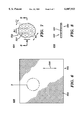
- FIG. 4 is a cutaway, sectional, partial, side representation of gas diffusion layers entering flow channels on flow field plate faces in a fuel cell of a fuel cell assembly;
- FIG. 5 is a cutaway, sectional, partial, side representation of a first exemplary embodiment of support members disposed in a fuel cell of the fuel cell assembly of FIG. 1, illustrating the support members holding gas diffusion layers out of flow field plate channels, and buttressing contact between a membrane electrode assembly and the gas diffusion layers, in accordance with the principles of the present invention
- FIG. 6 is a plan view of a second exemplary embodiment of the support member of the present invention, illustrating the support member as an expanded metal;
- FIG. 7 is a magnified, cutaway, partial, plan view directed at the region of the support member of FIG. 6 indicated by reference numeral 7;
- FIG. 8 is a cutaway, sectional, partial view directed substantially along line 8--8 of FIG. 7;
- FIG. 9 is a plan view of a third exemplary embodiment of the support member of the present invention, illustrating the support member as an etched metal;
- FIG. 10 is a magnified, cutaway, partial, plan view directed at the region of the support member of FIG. 9 indicated by reference numeral 10;
- FIG. 11 is a cutaway, sectional, partial view directed substantially along line 11--11 of FIG. 10;
- FIG. 12 is a plan view of a fourth exemplary embodiment of the support member of the present invention, illustrating the support member as a woven metal;
- FIG. 13 is a magnified, cutaway, partial, plan view directed at the region of the support member of FIG. 12 indicated by reference numeral 13;
- FIG. 14 is a cutaway, sectional, partial view directed substantially along line 14--14 of FIG. 13.
- a fuel cell assembly in which conductive and communicative support member(s) restrain resilient gas diffusion layer(s) from obstructing flow field plate channel(s), and buttress the resilient gas diffusion layer(s) for intimate contact with a membrane electrode assembly.
- FIG. 1 An example of a fuel cell assembly incorporating and using the novel features of the present invention is depicted in FIG. 1 and described in detail herein.
- a fuel cell assembly 100 includes end plates 102 and 104, insulation layers 106 and 108, and current collector/conductor plates 110 and 112, with a working section 114 therebetween.
- the working section includes one or more active sections and can include a selected number of cooling sections, as will be understood by those skilled in the art. In one aspect, the one or more active sections can further serve to perform cooling for the fuel cell assembly.
- a number of structural members 116, such as tie-bolt(s), can be employed to join the end plates.
- Working section 114 includes a number of layers 118.
- the layers generally form fluid manifolds 150 for supplying fluids to, removing fluids from, and otherwise communicating and/or servicing fluids as desired within the working section, as will be appreciated by those skilled in the art.
- the layers of fuel cell assembly 100 might have applied thereto compressive pressure and/or stress which is approximately equivalent to, preferably, fifty to one thousand pounds per square inch, and, most preferably, two hundred to four hundred pounds per square inch.
- a plurality of layers 118 form one or more (e.g., one hundred and eight) PEM-type fuel cells 300 (FIG. 3).
- PEM-type fuel cells 300 FIG. 3
- the construction and utilization of PEM fuel cells is known in the art.
- FIG. 2 One example of a layer 118 of working section 114 is depicted in FIG. 2 as fluid flow plate 200.
- the plate has a fluid flow face 202 with one or more, for instance, substantially parallel and/or generally serpentine, flow channel(s) 204 thereon.
- the flow channels receive and transmit one or more fluids through ports 206 and 208 which are in fluid communication with corresponding fluid manifolds 150 and 150'.
- the flow channels can include respective inlet(s) 206 and outlet(s) 208 in fluid communication with corresponding entry and exit fluid manifolds 150 and 150'.
- flow channel(s) 204 through formation of solid sidewalls in fluid flow face 202, may have any preselected configuration(s), such as for providing and/or ensuring maximal, even, continuous, appropriate, desired and/or uniform fluid service and/or coverage for active area(s) of MEA 310 (FIG. 3), as described herein.
- a given fluid flow plate 200 may be a bipolar, monopolar, combined monopolar (e.g., anode cooler or cathode cooler), or cooling plate.
- the fluid flow plate serves as a flow field plate and flow channels 204 conduct fluid which includes reactant fluid for fuel cell assembly 100.
- the reactant fluid serves as fuel or oxidant for a given fuel cell 300 (FIG. 3).
- the flow channels can carry reactant gas (e.g., a fuel such as hydrogen or an oxidant such as air/oxygen) as well as vapor and/or liquid (e.g., humidification and/or product water), as will be understood by those skilled in the art.
- a typical fluid flow plate 200 might have a height which is preferably in the range 1.0 to 20.0 in., and is most preferably in the range 6.0 to 10.0 in. Additionally, the width of the fluid flow plate is preferably in the range 1.0 to 20.0 in., and is most preferably in the range 5.0 to 9.0 in. Further, the thickness of the fluid flow plate is preferably in the range 0.02 to 0.30 in., and is most preferably in the range 0.05 to 0.15 in.
- the cross-sectional dimension of width of a given flow channel 204 on face 202 is preferably in the range 0.01 to 0.10 in., and is most preferably in the range 0.02 to 0.05 in., with the cross-sectional dimension of depth of the flow channel preferably in the range 0.005 to 0.080 in., and most preferably in the range 0.010 to 0.050 in.
- the cross-sectional dimension of width of a land separating adjacent flow channel sections for example, land 314, 314' (FIG. 3)
- fluid flow plate 200 has a number of (e.g., peripheral) holes 210 therethrough, which can cooperate in formation of fluid manifolds, such as fluid manifolds 150, of fuel cell assembly 100.
- the perimeters of layers 118 are formed with minimal amounts of material disposed generally transversely beyond the active extent of working section 114 as well as the fluid manifolds of the fuel cell assembly, as represented in FIG. 2.
- the fluid flow plate may be formed with a material such as non-magnetic, austenitic stainless steel.
- a material such as titanium may be employed.
- gasketing material or gaskets 304, 304' can be employed to seal peripheral holes 210 (FIG. 2), and can cooperate with the longitudinal extents of layers 118 in formation of the fluid manifolds.
- a given gasket 304, 304' might take the form of, for instance, a frame gasket made from a polytetrafluoroethylene (“PTFE") material manufactured by E. I. DuPont de Nemours Company and sold under the trademark TEFLON®.
- PTFE polytetrafluoroethylene
- O-ring gasket(s) might be employed.
- FIG. 3 depicts fuel cell 300 with fluid flow plates 200 and 200' serving as flow field plates.
- flow field plate 200 might serve as an anode side of the fuel cell
- flow field plate 200' might serve as a cathode side of the fuel cell.
- face 202 might comprise an anode face
- face 202' might comprise a cathode face.
- flow channels 204 might carry hydrogen, as fuel, and humidification water (vapor and/or liquid).
- flow channels 204' might carry air/oxygen, as oxidant, as well as humidification water (vapor and/or liquid) and/or product water (vapor and/or liquid), as will be understood by those skilled in the art.
- Fuel cell 300 includes membrane or solid electrolyte 306.
- solid electrolyte 306 comprises a solid polymer electrolyte made using a polymer such as a material manufactured by E. I. DuPont de Nemours Company and sold under the trademark NAFION®.
- an active electrolyte such as sulfonic acid groups might be included in this polymer.
- the solid polymer electrolyte might be formed with a product manufactured by W. L. Gore & Associates (Elkton, Md.) and sold under the trademark GORE-SELECT®.
- catalysts 308 and 308' e.g., platinum
- This unit can be referred to as a "membrane electrode assembly" (hereinafter "MEA") 310.
- MEA membrane electrode assembly
- the MEA might be formed with a product manufactured by W. L. Gore & Associates and sold under the trade designation PRIMEA 5510-HS.
- MEA 310 is sandwiched between anode and cathode gas diffusion layers (hereinafter “GDLs”) 312 and 312', respectively, which are preferably formed with a resilient and conductive material such as carbon fabric, carbon fiber paper, carbon cloth or carbon paper.
- GDLs cathode gas diffusion layers
- An exemplary gas diffusion layer (hereinafter "GDL") 312, 312' may have a nominal thickness which is preferably in the range 0.005 to 0.030 in., and is most preferably in the range 0.010 to 0.020 in.
- GDL gas diffusion layer
- resiliency of the GDL exists with respect to an operative condition thereof, for instance, under a certain range of compression in fuel cell assembly 100, and with a particular range of expected expansion and/or contraction for the GDL.
- porous carbon cloth or paper is infused with a slurry of carbon black and sintered with TEFLON® material.
- the anode and cathode GDLs serve as electrochemical conductors between catalyzed sites of solid polymer electrolyte 306 and the fuel (e.g., hydrogen) and oxidant (e.g., air/oxygen) which each flow in anode and cathode flow channels 204 and 204', respectively.
- the GDLs also present to the surfaces of MEA 310 a combination of microscopic porosity and macroscopic porosity. Microscopic porosity allows reactant gas molecules to pass generally longitudinally from the flow channels to a surface of the MEA.
- Macroscopic porosity allows product water formed at the cathode surface of the MEA to be removed therefrom by flowing generally longitudinally into the cathode flow channels, to prevent flooding of the catalyst particles.
- deionized water might be added to a given reactant gas stream conducted by flow channel(s) 204, 204'.
- the water would desirably serve to humidify membrane 306.
- such a reactant gas stream may be humidified in any of a variety of ways, as will be understood by those skilled in the art.
- lands 314 and 314' may serve as contact positions on corresponding anode and cathode faces 202 and 202'.
- the land(s) 314, 314' may be formed, for instance, with a material such as non-magnetic, austenitic stainless steel. In another example, a material such as titanium may be employed.
- GDL 312 is located between lands 314 and (e.g., catalyst 308) the anode side of MEA 310, and GDL 312' is located between the lands 314' and (e.g., catalyst 308') the cathode side of the MEA.
- GDLs 312 and 312' comprise resilient material, as described herein.
- resiliency of GDLs 312 and 312' serves to promote conductivity for fuel cell assembly 100.
- resiliency of the GDLs can allow maximal conductive path(s) to be established between MEA 310 and contact position(s) on face(s) 202, 202', while accommodating imperfection(s) and/or shaping of adjacent component(s), as will be appreciated by those skilled in the art.
- space(s) and/or gap(s) can develop and/or be formed, as will be understood by those skilled in the art. For instance, a shift and/or separation might occur among the layers of the fuel cell assembly, such as during transportation and/or operation thereof. Should such space(s) develop proximate to a GDL 312, 312', in one example, resiliency of the GDL(s) may advantageously serve to occupy and/or close certain (e.g., proximate) space(s), and maintain conductive path(s) between surface(s) of MEA 310 and contact position(s) on face(s) 202, 202'.
- a certain degree of resiliency in the fuel cell assembly is desirable, for instance, in order to maintain pressure for an interface between the MEA and GDLs, in view of thermal expansion of various component(s), such as during start-up, shut-down, and/or loading variation(s).
- resiliency of GDLs 312 and 312' serves to promote fluid service for fuel cell assembly 100.
- the GDL(s) may ensure reactant fluid and/or humidification water (vapor and/or liquid) is communicated, guided, dispersed and/or distributed substantially evenly between MEA 310 and flow channel(s) 204, 204', thereby desirably preventing starvation of portion(s) of the MEA and/or promoting maximal performance of fuel cell 300.
- the GDL(s) may ensure proper communication of product fluid (e.g., vapor and/or liquid water), unused humidification water (vapor and/or liquid), and/or unused reactant fluid, from the MEA to the flow channel(s), thereby advantageously preventing flooding of portion(s) of the MEA and/or promoting enhanced operation of the fuel cell.
- product fluid e.g., vapor and/or liquid water
- unused humidification water vapor and/or liquid
- a bevel spring (not shown) between end plate 102, 104 and a nut for a tie-bolt serving as a structural member 116, as will be understood by those skilled in the art.
- FIG. 4 depicts fuel cell 400 whose performance is diminished under a longitudinal compression applied thereto.
- a compressive stress and/or pressure e.g., naively
- aimed at promoting conductivity through GDL 312, 312' has attendant deleterious consequence(s) of encouraging, permitting, and/or allowing the GDL(s) to encroach upon, impinge, deflect and/or sag into certain and/or corresponding flow channel(s) 204, 204', in view of the resiliency of the GDL(s).
- the consequent restriction, blockage, obstruction and/or clogging of the flow channel(s) can undesirably decrease and/or alter fluid flow and/or fluid throughput, thereby harming and/or reducing fluid(s) service for MEA 310.
- the present invention serves to reduce such harm(s) to fuel cell assembly 100, as described herein.
- fuel cell 500 advantageously includes support members 520, 520' located between respective GDLs 312, 312' and corresponding flow faces 202, 202', in accordance with the principles of the present invention.
- support member 520 may be formed from an expanded metal (e.g., support member 620 depicted in FIGS. 6-8), an etched metal (e.g., support member 720 depicted in FIGS. 9-11), a woven metal (e.g., support member 820 depicted in FIGS. 12-14), a perforated foil, or a screen.
- the support member may be formed with a material such as non-magnetic, austenitic stainless steel.
- a material such as titanium may be employed.
- support member 520 includes first side 530 and second side 532. Also, the support member is formed with openings 534 extending therethrough, for fluid communication between flow channel(s) 204 and GDL 312.
- first side 530 of support member 520 abuts flow field plate face 202.
- second side 532 of the support member abuts GDL 312.
- the second side of the support member serves to restrain the GDL against entering flow channel(s) 204, such as under a compressive force applied to fuel cell assembly 100.
- support member 520 desirably serves to promote fluid service for MEA 310.
- the present invention serves to avoid pressure-drop increase(s) along the flow channel lengths, for advantageous energy savings, flow uniformity, and/or performance.
- second side 532 of support member 520 can maintain a clamping pressure for interface 550 between GDL 312 and MEA 310. Therefore, the support member serves to promote electrical conductivity for fuel cell assembly 100. In particular, the invention serves to increase contact pressure between the MEA and GDL(s), for enhanced mechanical support, electrical conductivity, and/or operability.
- support member 520 may serve to provide transverse conductive path(s) between GDL 312 and contact position(s) (e.g., lands 314) of fluid flow face 202.
- the support member may provide enhanced electrical coupling for the GDL(s), such as over section(s) of the flow channel(s) where the GDL(s) would otherwise be uncoupled.
- electrons may be conducted through the support member generally transversely, between the contact position(s), such as the land(s), of the fluid flow face, and position(s) of the GDL(s) located over the flow channel(s), in accordance with the principles of the present invention.
- the present invention provides comparable and/or cooperative mechanical support, electrical conductivity, and/or operability advantage(s) with respect to first side 530', second side 532', and conductive path(s) of support member 520', as well as with respect to interface 550' between GDL 312' and MEA 310.
- FIG. 5 depicts matched, coordinated, and/or aligned pitch among openings 534 of support member 520 and portions of flow channel(s) 204, as well as among certain solid parts of the support member and portions of lands 314, with the thickness of the support member cooperatively serving to hold GDL 312 out of the flow channel(s).
- Design choice(s) allow numerous variation(s) among such relationship(s), in accordance with the principles of the present invention. For example, referring to FIG.
- the pitch for the support member might be uniformly or non-uniformly (e.g., fractionally) reduced, so solid section(s) of the support member superimpose part(s) of the flow channel(s), and/or the opening(s) might be staggered.
- the openings may have any appropriate shape(s) and/or preselected configuration(s).
- FIGS. 6, 9, and 12 depict exemplary relative orientations for the support members 620, 720, and 820, respectively, with respect to illustrative, relative, lengthwise orientations 540, 542, and 544, respectively, for one or more of straight, serpentine, and/or parallel flow channel(s) 204 (FIGS. 2 and 5).
- FIGS. 5-14 depict a number of exemplary constructions for support member(s), such as support member 520 (FIG. 5), of the present invention.
- support member 620 may comprise an expanded metal, as depicted in FIGS. 6-8.
- support member 720 may comprise an etched metal, as depicted in FIGS. 9-11.
- support member 820 may comprise a woven metal, as depicted in FIGS. 12-14.
- a typical support member such as one or more of support members 520, 620, 720 and 820, might have a thickness which is preferably in the range 0.001 to 0.016 in., and is most preferably in the range 0.002 to 0.008 in.
- major and minor transverse dimensions e.g., exemplary dimensions A1 and A2 depicted in FIG. 10
- a pitch e.g., one or more of distances B1-B6 depicted in FIGS.
- a transverse dimension (e.g., one or more of dimensions C1-C4 depicted in FIGS. 7, 10, and 13) of material interposed between successive openings 534 is preferably in the range 0.002 to 0.040 in., and is most preferably in the range 0.004 to 0.020 in.
- support member 520 may be formed spikeless and/or substantially flat, such as is represented in FIGS. 5, 8, 11, and 14.
- spikelessness and/or substantial flatness provides a good electrical interface between mating surfaces of first side 530 and contact position(s) (e.g., lands 314) of fluid flow face 202.
- spikelessness and/or substantial flatness provides, enhances, and/or buttresses uniform, non-destructive, and/or thorough mating between active area(s) of MEA 310 and GDL(s) 312, 312'.
- spikelessness, substantial flatness, and/or integrity of support member 520 serves to minimize occurrence(s) and/or adverse effect(s) of deflection(s) in fuel cell assembly 100.
- a deflection may present a problem, since the component(s) and layers consequently might tend to not be held together as tightly as planned and/or desired.
- electrical conductivity may be enhanced by maximizing contact among the layers of the fuel cell assembly, which contact may often be premised upon the mating and/or meeting of adjacent (e.g., substantially flat) surfaces.
- deflection(s) may force imperfection(s) and/or defect(s) into such arrangement(s), for decreased performance of the fuel cell assembly.
- the support member may provide enhanced stability to the GDL(s), such as over section(s) of the flow channel(s) where the GDL(s) would otherwise be (e.g., generally and/or externally) longitudinally unsupported.
- Such enhanced stability may advantageously serve to more uniformly and/or evenly distribute force(s) and/or pressure(s), for instance, for superior, improved, and/or more thorough electrical coupling among surface(s) of MEA 310 and the GDL(s).
- Flow channel(s) 204 may be formed with variable cross section(s), in accordance with the principles of the subject invention.
- each of the plurality of flow channels is preferably formed having substantially the same length.
- the flow channels By designing the flow channels to have substantially identical length, one largely prevents variance in pressure drop among the flow channels, thereby promoting uniform and equal flow as well as superior overall performance. Further, any variance in cross-section along a given flow channel, is preferably substantially duplicated for companion flow channel(s) on the same fluid flow face which carry the same fluid for a same fuel cell.
- a given fluid flow plate of the present invention which conducts fluids on both faces might be configured so the fluids have, for example, parallel flow or counter flow among various (e.g., generally serpentine) flow channels.
- a parallel flow configuration might generally transversely align flow on the opposing faces by positioning corresponding first and second inlets at opposite sides of a first corner of the plate, and corresponding first and second outlets at opposite sides of a generally diametrically opposed second corner of the plate.
- a counter flow design might provide flow in generally transversely opposite directions on the opposing faces by placing first inlet(s) and second outlet(s) at opposite sides of a first corner of the plate, and first outlet(s) and second inlet(s), respectively, at opposite sides of a generally diametrically opposed second corner of the plate.
- Operation of a fuel cell assembly of the present invention can include periods or intervals of action and inaction, such as an active use followed by idling. Also, the fuel cell assembly can be employed for varied (e.g., automotive to aerospace to industrial) applications, in various environments.
- Fluid flow plate 200 and/or fluid manifold(s) 150, 150' could serve any desired function with any appropriate orientation, shape, and/or formation in any position of fuel cell assembly 100.
- fluid flow face 202 could easily have any number of flow channels 204.
- Any flow channel 204 could easily have any appropriate shape or structure.
- flow channel(s) 204 could easily be configured to deviate, to any desired degree, from parallel alignment and/or serpentine design.
- any of port(s)/inlet(s) 206 and/or port(s)/outlet(s) 208 might employ any mechanism for fluid communication between appropriate flow channel(s) 204 and fluid manifold(s) 150, 150'.
- fluid flow plate(s) 200 could easily be employed in any appropriate type(s) of fuel cell(s).
- working section 114 could easily include any desired type(s) of fuel cell(s).
Abstract
Description
Claims (44)
Priority Applications (1)
| Application Number | Priority Date | Filing Date | Title |
|---|---|---|---|
| US09/067,098 US6007933A (en) | 1998-04-27 | 1998-04-27 | Fuel cell assembly unit for promoting fluid service and electrical conductivity |
Applications Claiming Priority (1)
| Application Number | Priority Date | Filing Date | Title |
|---|---|---|---|
| US09/067,098 US6007933A (en) | 1998-04-27 | 1998-04-27 | Fuel cell assembly unit for promoting fluid service and electrical conductivity |
Publications (1)
| Publication Number | Publication Date |
|---|---|
| US6007933A true US6007933A (en) | 1999-12-28 |
Family
ID=22073689
Family Applications (1)
| Application Number | Title | Priority Date | Filing Date |
|---|---|---|---|
| US09/067,098 Expired - Lifetime US6007933A (en) | 1998-04-27 | 1998-04-27 | Fuel cell assembly unit for promoting fluid service and electrical conductivity |
Country Status (1)
| Country | Link |
|---|---|
| US (1) | US6007933A (en) |
Cited By (77)
| Publication number | Priority date | Publication date | Assignee | Title |
|---|---|---|---|---|
| WO2000031813A1 (en) * | 1998-11-23 | 2000-06-02 | Forschungszentrum Jülich GmbH | Fuel cell with operating material that is introduced via a perforated plate |
| WO2000041260A2 (en) * | 1998-12-30 | 2000-07-13 | Ballard Power Systems Inc. | Fuel cell fluid flow field plate and methods of making fuel cell flow field plates |
| US6251308B1 (en) | 1999-03-19 | 2001-06-26 | Premix | Highly conductive molding compounds and fuel cell bipolar plates comprising these compounds |
| EP1184925A2 (en) * | 2000-08-31 | 2002-03-06 | dmc2 Degussa Metals Catalysts Cerdec AG | PEM fuel cell stack |
| US6365069B2 (en) | 1999-03-19 | 2002-04-02 | Quantum Composites Inc. | Process of injection molding highly conductive molding compounds and an apparatus for this process |
| US6436315B2 (en) | 1999-03-19 | 2002-08-20 | Quantum Composites Inc. | Highly conductive molding compounds for use as fuel cell plates and the resulting products |
| US20020142205A1 (en) * | 2001-03-31 | 2002-10-03 | Samsung Electronics Co., Ltd. | Proton Exchange Membrane Fuel Cell Stack |
| US6468682B1 (en) | 2000-05-17 | 2002-10-22 | Avista Laboratories, Inc. | Ion exchange membrane fuel cell |
| US20020172854A1 (en) * | 1999-12-16 | 2002-11-21 | Herbert Hartnack | Fuel cell block |
| US20020192531A1 (en) * | 1998-12-30 | 2002-12-19 | Joerg Zimmerman | Liquid reactant flow field plates for liquid feed fuel cells |
| WO2002101859A2 (en) * | 2001-06-13 | 2002-12-19 | Bayerische Motoren Werke Aktiengesellschaft | Fuel cell and method for producing such a fuel cell |
| US20030054226A1 (en) * | 2000-01-25 | 2003-03-20 | Minoru Kaneko | Fuel cell |
| US20030059662A1 (en) * | 2001-09-17 | 2003-03-27 | 3M Innovative Properties Company | Flow field |
| US6541145B2 (en) * | 2000-05-09 | 2003-04-01 | Ballard Power Systems, Inc. | Flow fields for supporting fluid diffusion layers in fuel cells |
| US6555261B1 (en) * | 1998-10-29 | 2003-04-29 | 3M Innovative Properties Company | Microstructured flow fields |
| US20030091887A1 (en) * | 2000-07-07 | 2003-05-15 | Ab Volvo | Polymer fuel cell structure |
| US20030165720A1 (en) * | 2002-03-04 | 2003-09-04 | Mti Microfuel Cells Inc. | Method and apparatus for water management of a fuel cell system |
| US20030168638A1 (en) * | 2001-12-17 | 2003-09-11 | Butler Kurt I. | Highly conductive molding compounds having an increased distribution of large size graphite particles |
| US20030175575A1 (en) * | 2002-02-28 | 2003-09-18 | Omg Ag & Co. Kg | PEM fuel cell stack and method of making same |
| WO2003092091A2 (en) * | 2002-04-23 | 2003-11-06 | Nuvera Fuel Cells Europe S.R.L. | Membrane electrochemical generator containing a bipolar plate with a plurality of holes to distribute the gases |
| US20030215692A1 (en) * | 2002-04-30 | 2003-11-20 | Rock Jeffrey A. | Bipolar plate assembly having transverse legs |
| WO2004008562A1 (en) | 2002-07-15 | 2004-01-22 | Toyota Jidosha Kabushiki Kaisha | Fuel cell |
| US20040023100A1 (en) * | 2001-02-12 | 2004-02-05 | Boff James Charles | Flow field plate geometries |
| US20040038117A1 (en) * | 2000-08-16 | 2004-02-26 | Tennison Stephen Robert | Fuel cell structure |
| US6699613B2 (en) * | 2000-05-02 | 2004-03-02 | Honda Giken Kogyo Kabushiki Kaisha | Fuel cell having sealant for sealing a solid polymer electrolyte membrane |
| US20040053105A1 (en) * | 2000-11-08 | 2004-03-18 | Felix Blank | Fuel cell stack |
| EP1403947A2 (en) * | 2002-08-07 | 2004-03-31 | Matsushita Electric Industrial Co., Ltd. | Fuel cell |
| US6756147B1 (en) * | 1999-05-28 | 2004-06-29 | Heliocentris Energiesysteme Gmbh | Membrane electrode unit comprising an integrated sealing edge |
| US20040137309A1 (en) * | 2002-11-18 | 2004-07-15 | Gencell Corporation | Bipolar plate with two-pass anode |
| US20040202911A1 (en) * | 1999-10-19 | 2004-10-14 | Honda Giken Kogyo Kabushiki Kaisha | Full cell stack |
| US20040202917A1 (en) * | 2003-04-14 | 2004-10-14 | Daryl Chapman | Variable pressure drop stack |
| US20040202907A1 (en) * | 2003-04-14 | 2004-10-14 | Daryl Chapman | Flow control for multiple stacks |
| US20040213902A1 (en) * | 2003-02-20 | 2004-10-28 | Seiko Epson Corporation | System and method for manufacturing a fuel cell |
| US20040229100A1 (en) * | 1999-10-19 | 2004-11-18 | Honda Giken Kogyo Kabushiki Kaisha | Fuel cell stack |
| US20040247986A1 (en) * | 2003-04-09 | 2004-12-09 | Shinsuke Takeguchi | Polymer electrolyte fuel cell |
| EP1501142A2 (en) * | 2003-07-24 | 2005-01-26 | Nissan Motor Co., Ltd. | Fuel cell collector structure and solid oxide fuel cell stack using the same |
| US20050064263A1 (en) * | 2003-09-24 | 2005-03-24 | Goebel Steven G. | Flow field plate arrangement for a fuel cell |
| WO2005028710A1 (en) * | 2003-09-22 | 2005-03-31 | Hydrogenics Corporation | Electrolyzer cell arrangement |
| US20050133364A1 (en) * | 2003-12-18 | 2005-06-23 | Andrei Leonida | Electrolyte support member for high differential pressure electrochemical cell |
| US20050186458A1 (en) * | 2003-09-22 | 2005-08-25 | Ali Rusta-Sallehy | Electrolyzer cell stack system |
| US20050197743A1 (en) * | 2003-09-22 | 2005-09-08 | Ali Rusta-Sallehy | Electrolyzer cell stack system |
| US20050221152A1 (en) * | 2002-06-24 | 2005-10-06 | Turpin Mark C | Flow field plate geometries |
| US20060003208A1 (en) * | 2004-06-30 | 2006-01-05 | Haycock Steven M | Overmolded support plate for fuel cell |
| WO2006016462A1 (en) * | 2004-08-09 | 2006-02-16 | Nissan Motor Co., Ltd. | Fuel cell having fuel and oxidation gas channels of different cross-sections |
| US20060040166A1 (en) * | 2004-08-18 | 2006-02-23 | Budinski Michael K | Fuel cell side plates with controlled tensile compliance |
| US20060078780A1 (en) * | 2003-08-06 | 2006-04-13 | Margiott Paul R | Hydrogen passivation shut down system for a fuel cell power plant |
| US7081314B2 (en) * | 2000-05-02 | 2006-07-25 | Honda Giken Kogyo Kabushiki Kaisha | Fuel cell having sealant for sealing a solid polymer electrolyte membrane |
| US20060188773A1 (en) * | 2003-03-25 | 2006-08-24 | Peter Andrin | Process for joining a gas diffusion layer to a separator plate |
| US20060251944A1 (en) * | 2002-03-26 | 2006-11-09 | Matsushita Electric Industrial Co., Ltd. | Polymer electrolyte fuel cell |
| US20060280999A1 (en) * | 2004-07-30 | 2006-12-14 | Sumitomo Chemical Company, Limited | Polymer electrolyte fuel cell |
| US20070015035A1 (en) * | 2001-03-16 | 2007-01-18 | Creare Inc. | Lightweight direct methanol fuel cell and supporting systems |
| US20070105000A1 (en) * | 2003-06-18 | 2007-05-10 | The Morgan Crucible Company Plc | Flow field plate geometries |
| CN1326280C (en) * | 2000-08-18 | 2007-07-11 | 霍尼韦尔国际公司 | Sealless radial solid oxide fuel cell stack design |
| JP2008066208A (en) * | 2006-09-11 | 2008-03-21 | Honda Motor Co Ltd | Fuel cell |
| US20080075989A1 (en) * | 2006-09-26 | 2008-03-27 | Casio Computer Co., Ltd. | Fuel cell, fuel cell stack, fuel cell apparatus and electronic instrument |
| US20080113243A1 (en) * | 2005-01-14 | 2008-05-15 | Tsutomu Kawashima | Fuel-Cell Stack And Fuel Cell |
| US20080160386A1 (en) * | 2006-12-27 | 2008-07-03 | Matsushita Electric Industrial Co., Ltd. | Fuel Cell |
| CN100405647C (en) * | 2005-03-18 | 2008-07-23 | 松下电器产业株式会社 | Direct methanol fuel cell |
| US20090246588A1 (en) * | 2008-03-29 | 2009-10-01 | Coretronic Corporation | Planar fuel cell device |
| US20100062303A1 (en) * | 2008-09-08 | 2010-03-11 | Joongmyeon Bae | Metal-supported solid oxide fuel cell and manufacturing method thereof |
| US20100062302A1 (en) * | 2008-09-08 | 2010-03-11 | Joongmyeon Bae | Metal support and solid oxide fuel cell including the same |
| US20100124690A1 (en) * | 2008-11-04 | 2010-05-20 | Industrial Technology Research Institute | Fuel cell fluid flow plate with shell passageway piece |
| US20100209801A1 (en) * | 2008-09-18 | 2010-08-19 | Miho Gemba | Fuel cell and fuel cell stack comprising the same |
| CN101946349A (en) * | 2008-06-16 | 2011-01-12 | 丰田车体株式会社 | Gas flow passage forming member, method of manufacturing the gas flow passage forming member, and device for forming the gas flow passage forming member |
| US20110053052A1 (en) * | 2009-08-28 | 2011-03-03 | Enerfuel, Inc. | Fuel cell composite flow field element and method of forming the same |
| US20110314928A1 (en) * | 2010-06-29 | 2011-12-29 | Hyundai Motor Company | Apparatus and method for non-destructive measurement of bending stiffness of gdl for fuel cell |
| WO2013095380A1 (en) * | 2011-12-20 | 2013-06-27 | United Technologies Corporation | Flow battery with carbon paper |
| EP2741359A1 (en) | 2012-12-10 | 2014-06-11 | Commissariat A L'energie Atomique Et Aux Energies Alternatives | Cell for fuel cell with proton-exchange membrane, with gas diffusion layers having different rigidity in the anode and the cathode |
| CN105531859A (en) * | 2013-07-10 | 2016-04-27 | 日产自动车株式会社 | Fuel cell unit cell |
| DE102016122590A1 (en) | 2016-11-23 | 2018-05-24 | Audi Ag | Polar plate for a fuel cell and fuel cell stack |
| DE102016122587A1 (en) | 2016-11-23 | 2018-05-24 | Audi Ag | Polar plate arrangement for a fuel cell and single cell |
| US20190049148A1 (en) * | 2016-02-09 | 2019-02-14 | Sermeta | Deflector for condensation heat exchanger and exchanger provided with such a deflector |
| WO2019046108A2 (en) | 2017-08-28 | 2019-03-07 | Ballard Power Systems Inc. | Flow field plate for electrochemical fuel cells |
| US11056698B2 (en) | 2018-08-02 | 2021-07-06 | Raytheon Technologies Corporation | Redox flow battery with electrolyte balancing and compatibility enabling features |
| US11271226B1 (en) | 2020-12-11 | 2022-03-08 | Raytheon Technologies Corporation | Redox flow battery with improved efficiency |
| WO2022153060A1 (en) * | 2021-01-15 | 2022-07-21 | Afc Energy Plc | Bipolar plate and resilient conduction member |
| DE102021128606A1 (en) | 2021-11-03 | 2023-05-04 | MTU Aero Engines AG | fuel cell |
Citations (10)
| Publication number | Priority date | Publication date | Assignee | Title |
|---|---|---|---|---|
| US4091176A (en) * | 1975-03-11 | 1978-05-23 | Stamicarbon, B.V. | Porous electrode |
| US4345986A (en) * | 1980-06-02 | 1982-08-24 | Ppg Industries, Inc. | Cathode element for solid polymer electrolyte |
| US4410410A (en) * | 1981-03-30 | 1983-10-18 | The Dow Chemical Company | Internally supported electrode |
| US4476002A (en) * | 1982-06-29 | 1984-10-09 | Union Carbide Corporation | Metal current carrier for electrochemical cell electrodes |
| US4602426A (en) * | 1985-06-28 | 1986-07-29 | Union Carbide Corporation | Method of producing a gas diffusion electrode |
| US4636291A (en) * | 1984-06-30 | 1987-01-13 | Kernforschungsanlage Julich Gesellschaft Mit Beschrankter Haftung | Diaphragm for alkaline electrolysis and process for manufacture of diaphragm |
| US5482792A (en) * | 1993-04-30 | 1996-01-09 | De Nora Permelec S.P.A. | Electrochemical cell provided with ion exchange membranes and bipolar metal plates |
| US5558948A (en) * | 1994-11-09 | 1996-09-24 | Energy Research Corporation | Fuel cell anode and fuel cell |
| US5707755A (en) * | 1996-12-09 | 1998-01-13 | General Motors Corporation | PEM/SPE fuel cell |
| US5709961A (en) * | 1996-06-06 | 1998-01-20 | Lynntech, Inc. | Low pressure fuel cell system |
-
1998
- 1998-04-27 US US09/067,098 patent/US6007933A/en not_active Expired - Lifetime
Patent Citations (11)
| Publication number | Priority date | Publication date | Assignee | Title |
|---|---|---|---|---|
| US4091176A (en) * | 1975-03-11 | 1978-05-23 | Stamicarbon, B.V. | Porous electrode |
| US4345986A (en) * | 1980-06-02 | 1982-08-24 | Ppg Industries, Inc. | Cathode element for solid polymer electrolyte |
| US4410410A (en) * | 1981-03-30 | 1983-10-18 | The Dow Chemical Company | Internally supported electrode |
| US4476002A (en) * | 1982-06-29 | 1984-10-09 | Union Carbide Corporation | Metal current carrier for electrochemical cell electrodes |
| US4636291A (en) * | 1984-06-30 | 1987-01-13 | Kernforschungsanlage Julich Gesellschaft Mit Beschrankter Haftung | Diaphragm for alkaline electrolysis and process for manufacture of diaphragm |
| US4602426A (en) * | 1985-06-28 | 1986-07-29 | Union Carbide Corporation | Method of producing a gas diffusion electrode |
| US5482792A (en) * | 1993-04-30 | 1996-01-09 | De Nora Permelec S.P.A. | Electrochemical cell provided with ion exchange membranes and bipolar metal plates |
| US5565072A (en) * | 1993-04-30 | 1996-10-15 | De Nora Permelec S.P.A. | Electrochemical cell provided with ion exchange membranes and bipolar metal plates |
| US5558948A (en) * | 1994-11-09 | 1996-09-24 | Energy Research Corporation | Fuel cell anode and fuel cell |
| US5709961A (en) * | 1996-06-06 | 1998-01-20 | Lynntech, Inc. | Low pressure fuel cell system |
| US5707755A (en) * | 1996-12-09 | 1998-01-13 | General Motors Corporation | PEM/SPE fuel cell |
Cited By (173)
| Publication number | Priority date | Publication date | Assignee | Title |
|---|---|---|---|---|
| US6555261B1 (en) * | 1998-10-29 | 2003-04-29 | 3M Innovative Properties Company | Microstructured flow fields |
| WO2000031813A1 (en) * | 1998-11-23 | 2000-06-02 | Forschungszentrum Jülich GmbH | Fuel cell with operating material that is introduced via a perforated plate |
| US20020192531A1 (en) * | 1998-12-30 | 2002-12-19 | Joerg Zimmerman | Liquid reactant flow field plates for liquid feed fuel cells |
| WO2000041260A2 (en) * | 1998-12-30 | 2000-07-13 | Ballard Power Systems Inc. | Fuel cell fluid flow field plate and methods of making fuel cell flow field plates |
| WO2000041260A3 (en) * | 1998-12-30 | 2000-11-30 | Ballard Power Systems | Fuel cell fluid flow field plate and methods of making fuel cell flow field plates |
| US6251308B1 (en) | 1999-03-19 | 2001-06-26 | Premix | Highly conductive molding compounds and fuel cell bipolar plates comprising these compounds |
| US6365069B2 (en) | 1999-03-19 | 2002-04-02 | Quantum Composites Inc. | Process of injection molding highly conductive molding compounds and an apparatus for this process |
| US6436315B2 (en) | 1999-03-19 | 2002-08-20 | Quantum Composites Inc. | Highly conductive molding compounds for use as fuel cell plates and the resulting products |
| US20030042468A1 (en) * | 1999-03-19 | 2003-03-06 | Quantum Composites Inc. | Highly conductive molding compounds for use as fuel cell plates and the resulting products |
| US6756147B1 (en) * | 1999-05-28 | 2004-06-29 | Heliocentris Energiesysteme Gmbh | Membrane electrode unit comprising an integrated sealing edge |
| US7527889B2 (en) * | 1999-10-19 | 2009-05-05 | Honda Giken Kogyo Kabushiki Kaisha | Fuel cell stack |
| US20040229100A1 (en) * | 1999-10-19 | 2004-11-18 | Honda Giken Kogyo Kabushiki Kaisha | Fuel cell stack |
| US20040202911A1 (en) * | 1999-10-19 | 2004-10-14 | Honda Giken Kogyo Kabushiki Kaisha | Full cell stack |
| US7358000B2 (en) | 1999-10-19 | 2008-04-15 | Honda Giken Kogyo Kabushiki Kaisha | Full cell stack |
| US20020172854A1 (en) * | 1999-12-16 | 2002-11-21 | Herbert Hartnack | Fuel cell block |
| JP4846951B2 (en) * | 1999-12-16 | 2011-12-28 | シーメンス アクチエンゲゼルシヤフト | Fuel cell block |
| US6955862B2 (en) * | 1999-12-16 | 2005-10-18 | Siemens Aktiengesellschaft | Fuel cell block |
| US20030054226A1 (en) * | 2000-01-25 | 2003-03-20 | Minoru Kaneko | Fuel cell |
| US7348090B2 (en) * | 2000-01-25 | 2008-03-25 | Sanyo Electric Co., Ltd. | Fuel cell |
| US7081314B2 (en) * | 2000-05-02 | 2006-07-25 | Honda Giken Kogyo Kabushiki Kaisha | Fuel cell having sealant for sealing a solid polymer electrolyte membrane |
| US7651805B2 (en) | 2000-05-02 | 2010-01-26 | Honda Giken Kogyo Kabushiki Kaisha | Fuel cell having sealant for sealing a solid polymer electrolyte membrane |
| US20040137305A1 (en) * | 2000-05-02 | 2004-07-15 | Honda Giken Kogyo Kabushiki Kaisha | Fuel cell having sealant for sealing a solid polymer electrolyte membrane |
| US6699613B2 (en) * | 2000-05-02 | 2004-03-02 | Honda Giken Kogyo Kabushiki Kaisha | Fuel cell having sealant for sealing a solid polymer electrolyte membrane |
| US6541145B2 (en) * | 2000-05-09 | 2003-04-01 | Ballard Power Systems, Inc. | Flow fields for supporting fluid diffusion layers in fuel cells |
| US6743536B2 (en) | 2000-05-17 | 2004-06-01 | Relion, Inc. | Fuel cell power system and method of controlling a fuel cell power system |
| US6468682B1 (en) | 2000-05-17 | 2002-10-22 | Avista Laboratories, Inc. | Ion exchange membrane fuel cell |
| US7790330B2 (en) * | 2000-07-07 | 2010-09-07 | Powercell Sweden Ab | Polymer fuel cell structure |
| US20030091887A1 (en) * | 2000-07-07 | 2003-05-15 | Ab Volvo | Polymer fuel cell structure |
| US7544437B2 (en) * | 2000-08-16 | 2009-06-09 | Materials and Separation Technology International Limited | Fuel cell structure |
| US20040038117A1 (en) * | 2000-08-16 | 2004-02-26 | Tennison Stephen Robert | Fuel cell structure |
| CN1326280C (en) * | 2000-08-18 | 2007-07-11 | 霍尼韦尔国际公司 | Sealless radial solid oxide fuel cell stack design |
| KR100856337B1 (en) * | 2000-08-31 | 2008-09-04 | 우미코레 아게 운트 코 카게 | Polymer electrolyte fuel cell stack |
| EP1184925A3 (en) * | 2000-08-31 | 2006-09-20 | Umicore AG & Co. KG | PEM fuel cell stack |
| US6720104B2 (en) * | 2000-08-31 | 2004-04-13 | Dmc2 Degussa Metals Catalysts Cerdec Ag | PEM fuel cell stack |
| US20020051901A1 (en) * | 2000-08-31 | 2002-05-02 | Ralf Zuber | PEM fuel cell stack |
| EP1184925A2 (en) * | 2000-08-31 | 2002-03-06 | dmc2 Degussa Metals Catalysts Cerdec AG | PEM fuel cell stack |
| US20040053105A1 (en) * | 2000-11-08 | 2004-03-18 | Felix Blank | Fuel cell stack |
| US7335437B2 (en) * | 2000-11-08 | 2008-02-26 | Daimlerchrysler Ag | Fuel cell stack |
| US20040023100A1 (en) * | 2001-02-12 | 2004-02-05 | Boff James Charles | Flow field plate geometries |
| US7067213B2 (en) | 2001-02-12 | 2006-06-27 | The Morgan Crucible Company Plc | Flow field plate geometries |
| US20070015035A1 (en) * | 2001-03-16 | 2007-01-18 | Creare Inc. | Lightweight direct methanol fuel cell and supporting systems |
| US7189468B2 (en) * | 2001-03-16 | 2007-03-13 | Creare Inc. | Lightweight direct methanol fuel cell |
| US20020142205A1 (en) * | 2001-03-31 | 2002-10-03 | Samsung Electronics Co., Ltd. | Proton Exchange Membrane Fuel Cell Stack |
| US7335436B2 (en) * | 2001-03-31 | 2008-02-26 | Samsung Sdi Co., Ltd. | Proton exchange membrane fuel cell stack |
| US20040185326A1 (en) * | 2001-06-13 | 2004-09-23 | Franz-Josef Wetzel | Fuel cell and method for manufacturing such a fuel cell |
| WO2002101859A2 (en) * | 2001-06-13 | 2002-12-19 | Bayerische Motoren Werke Aktiengesellschaft | Fuel cell and method for producing such a fuel cell |
| WO2002101859A3 (en) * | 2001-06-13 | 2003-05-08 | Bayerische Motoren Werke Ag | Fuel cell and method for producing such a fuel cell |
| US6780536B2 (en) * | 2001-09-17 | 2004-08-24 | 3M Innovative Properties Company | Flow field |
| US20030059662A1 (en) * | 2001-09-17 | 2003-03-27 | 3M Innovative Properties Company | Flow field |
| US6752937B2 (en) | 2001-12-17 | 2004-06-22 | Quantum Composites, Inc. | Highly conductive molding compounds having an increased distribution of large size graphite particles |
| US20030168638A1 (en) * | 2001-12-17 | 2003-09-11 | Butler Kurt I. | Highly conductive molding compounds having an increased distribution of large size graphite particles |
| US20030175575A1 (en) * | 2002-02-28 | 2003-09-18 | Omg Ag & Co. Kg | PEM fuel cell stack and method of making same |
| US20030165720A1 (en) * | 2002-03-04 | 2003-09-04 | Mti Microfuel Cells Inc. | Method and apparatus for water management of a fuel cell system |
| US6824900B2 (en) | 2002-03-04 | 2004-11-30 | Mti Microfuel Cells Inc. | Method and apparatus for water management of a fuel cell system |
| WO2003077345A1 (en) * | 2002-03-04 | 2003-09-18 | Mechanical Technology, Inc. | Method and apparatus for water management of a fuel cell system |
| US20070015032A1 (en) * | 2002-03-04 | 2007-01-18 | Mti Microfuel Cells, Inc. | Method and apparatus for water management of a fuel cell system |
| EP1349228A3 (en) * | 2002-03-26 | 2009-10-21 | Panasonic Corporation | Polymer electrolyte fuel cell, method of manufacturing the same and inspection method therefor |
| US20060251944A1 (en) * | 2002-03-26 | 2006-11-09 | Matsushita Electric Industrial Co., Ltd. | Polymer electrolyte fuel cell |
| US8012646B2 (en) | 2002-03-26 | 2011-09-06 | Panasonic Corporation | Polymer electrolyte fuel cell provided with a tightening pressure |
| EP1504481A2 (en) † | 2002-04-23 | 2005-02-09 | Nuvera Fuel Cells Europe S.R.L. | Membrane electrochemical generator containing a bipolar plate with a plurality of holes to distribute the gases |
| WO2003092091A2 (en) * | 2002-04-23 | 2003-11-06 | Nuvera Fuel Cells Europe S.R.L. | Membrane electrochemical generator containing a bipolar plate with a plurality of holes to distribute the gases |
| EP1504481B2 (en) † | 2002-04-23 | 2009-11-04 | Nuvera Fuel Cells Europe S.R.L. | Membrane electrochemical generator containing a bipolar plate with a plurality of holes to distribute the gases |
| KR100986033B1 (en) * | 2002-04-23 | 2010-10-08 | 누베라 퓨엘 셀스 유로프 에스.아르.엘. | Membrane electrochemical generator |
| US20060251948A1 (en) * | 2002-04-23 | 2006-11-09 | Daniele Facchi | Membrane electrochemical generator |
| US7524574B2 (en) | 2002-04-23 | 2009-04-28 | Nuvera Fuel Cells Europe, S.R.L. | Membrane electrochemical generator |
| WO2003092091A3 (en) * | 2002-04-23 | 2004-02-12 | Nuvera Fuel Cells Europ Srl | Membrane electrochemical generator containing a bipolar plate with a plurality of holes to distribute the gases |
| US20030215692A1 (en) * | 2002-04-30 | 2003-11-20 | Rock Jeffrey A. | Bipolar plate assembly having transverse legs |
| US7081316B2 (en) * | 2002-04-30 | 2006-07-25 | General Motors Corporation | Bipolar plate assembly having transverse legs |
| US7838139B2 (en) | 2002-06-24 | 2010-11-23 | The Morgan Crucible Company Plc | Flow field plate geometries |
| US20050221152A1 (en) * | 2002-06-24 | 2005-10-06 | Turpin Mark C | Flow field plate geometries |
| US20050147870A1 (en) * | 2002-07-15 | 2005-07-07 | Haruyuki Nakanishi | Fuel cell |
| EP1553650A1 (en) * | 2002-07-15 | 2005-07-13 | Toyota Jidosha Kabushiki Kaisha | Fuel cell |
| US7510792B2 (en) | 2002-07-15 | 2009-03-31 | Toyota Jidosha Kabushiki Kaisha | Fuel cell with a tension in an in-plane direction |
| EP1553650A4 (en) * | 2002-07-15 | 2008-09-17 | Toyota Motor Co Ltd | Fuel cell |
| WO2004008562A1 (en) | 2002-07-15 | 2004-01-22 | Toyota Jidosha Kabushiki Kaisha | Fuel cell |
| EP1403947A3 (en) * | 2002-08-07 | 2006-01-18 | Matsushita Electric Industrial Co., Ltd. | Fuel cell |
| EP1403947A2 (en) * | 2002-08-07 | 2004-03-31 | Matsushita Electric Industrial Co., Ltd. | Fuel cell |
| US6960407B2 (en) | 2002-08-07 | 2005-11-01 | Matsushita Electric Industrial Co., Ltd. | Fuel cell |
| US20040137309A1 (en) * | 2002-11-18 | 2004-07-15 | Gencell Corporation | Bipolar plate with two-pass anode |
| US20040213902A1 (en) * | 2003-02-20 | 2004-10-28 | Seiko Epson Corporation | System and method for manufacturing a fuel cell |
| US20060188773A1 (en) * | 2003-03-25 | 2006-08-24 | Peter Andrin | Process for joining a gas diffusion layer to a separator plate |
| US20090280392A2 (en) * | 2003-03-25 | 2009-11-12 | E. I. Du Pont De Nemours And Company | Electrochemical cell component |
| US20070059581A1 (en) * | 2003-03-25 | 2007-03-15 | Peter Andrin | Electrochemical cell component |
| US20040247986A1 (en) * | 2003-04-09 | 2004-12-09 | Shinsuke Takeguchi | Polymer electrolyte fuel cell |
| US7678490B2 (en) | 2003-04-09 | 2010-03-16 | Panasonic Corporation | Polymer electrolyte fuel cell |
| US20040202917A1 (en) * | 2003-04-14 | 2004-10-14 | Daryl Chapman | Variable pressure drop stack |
| WO2004093215A2 (en) * | 2003-04-14 | 2004-10-28 | General Motors Corporation | Variable pressure drop stack |
| WO2004093215A3 (en) * | 2003-04-14 | 2005-06-09 | Gen Motors Corp | Variable pressure drop stack |
| US7749634B2 (en) * | 2003-04-14 | 2010-07-06 | Gm Global Technology Operations, Inc. | Flow control for multiple stacks |
| US6936362B2 (en) * | 2003-04-14 | 2005-08-30 | General Motors Corporation | Variable pressure drop stack |
| US20080233461A1 (en) * | 2003-04-14 | 2008-09-25 | General Motors Corporation | Flow control for multiple stacks |
| DE102004017501C5 (en) * | 2003-04-14 | 2009-12-24 | General Motors Corp. (N.D.Ges.D. Staates Delaware), Detroit | Fuel cell, fuel cell stack, process for their preparation and use of the fuel cell |
| US20040202907A1 (en) * | 2003-04-14 | 2004-10-14 | Daryl Chapman | Flow control for multiple stacks |
| US7396601B2 (en) * | 2003-04-14 | 2008-07-08 | General Motors Corporation | Flow control for multiple stacks |
| JP2006523933A (en) * | 2003-04-14 | 2006-10-19 | ゼネラル・モーターズ・コーポレーション | Variable pressure drop fuel cell stack |
| CN100388544C (en) * | 2003-04-14 | 2008-05-14 | 通用汽车公司 | Variable pressure drop stack |
| JP4783281B2 (en) * | 2003-04-14 | 2011-09-28 | ゼネラル・モーターズ・コーポレーション | Variable pressure drop fuel cell stack |
| US20070105000A1 (en) * | 2003-06-18 | 2007-05-10 | The Morgan Crucible Company Plc | Flow field plate geometries |
| EP1501142A2 (en) * | 2003-07-24 | 2005-01-26 | Nissan Motor Co., Ltd. | Fuel cell collector structure and solid oxide fuel cell stack using the same |
| US7338729B2 (en) | 2003-07-24 | 2008-03-04 | Nissan Motor Co., Ltd. | Fuel cell collector structure and solid oxide fuel cell stack using the same |
| EP1501142A3 (en) * | 2003-07-24 | 2007-02-28 | Nissan Motor Co., Ltd. | Fuel cell collector structure and solid oxide fuel cell stack using the same |
| US20050019642A1 (en) * | 2003-07-24 | 2005-01-27 | Nissan Motor Co., Ltd. | Fuel cell collector structure and solid oxide fuel cell stack using the same |
| US20060078780A1 (en) * | 2003-08-06 | 2006-04-13 | Margiott Paul R | Hydrogen passivation shut down system for a fuel cell power plant |
| US8419910B2 (en) | 2003-09-22 | 2013-04-16 | Hydrogenics Corporation | Electrolyzer cell stack system |
| US20050186458A1 (en) * | 2003-09-22 | 2005-08-25 | Ali Rusta-Sallehy | Electrolyzer cell stack system |
| US20050115825A1 (en) * | 2003-09-22 | 2005-06-02 | David Frank | Electrolyzer cell arrangement |
| US20090071819A1 (en) * | 2003-09-22 | 2009-03-19 | Ali Rusta-Sallehy | Electrolyzer cell stack system |
| WO2005028710A1 (en) * | 2003-09-22 | 2005-03-31 | Hydrogenics Corporation | Electrolyzer cell arrangement |
| US9580825B2 (en) | 2003-09-22 | 2017-02-28 | Hydrogenics Corporation | Electrolyzer cell stack system |
| US20050197743A1 (en) * | 2003-09-22 | 2005-09-08 | Ali Rusta-Sallehy | Electrolyzer cell stack system |
| US7353085B2 (en) | 2003-09-22 | 2008-04-01 | Hydrogenics Corporation | Electrolyzer cell stack system |
| US20050064263A1 (en) * | 2003-09-24 | 2005-03-24 | Goebel Steven G. | Flow field plate arrangement for a fuel cell |
| US8367270B2 (en) | 2003-09-24 | 2013-02-05 | GM Global Technology Operations LLC | Flow field plate arrangement for a fuel cell |
| US7462415B2 (en) | 2003-09-24 | 2008-12-09 | General Motors Corporation | Flow field plate arrangement for a fuel cell |
| US20080311459A1 (en) * | 2003-09-24 | 2008-12-18 | Gm Global Technology Operations, Inc. | Flow field plate arrangement for a fuel cell |
| US20050133364A1 (en) * | 2003-12-18 | 2005-06-23 | Andrei Leonida | Electrolyte support member for high differential pressure electrochemical cell |
| US7217472B2 (en) | 2003-12-18 | 2007-05-15 | Hamilton Sundstrand Corporation | Electrolyte support member for high differential pressure electrochemical cell |
| US20060003208A1 (en) * | 2004-06-30 | 2006-01-05 | Haycock Steven M | Overmolded support plate for fuel cell |
| US7687180B2 (en) * | 2004-06-30 | 2010-03-30 | Freudenberg-Nok General Partnership | Overmolded support plate for fuel cell |
| US20060280999A1 (en) * | 2004-07-30 | 2006-12-14 | Sumitomo Chemical Company, Limited | Polymer electrolyte fuel cell |
| EP1626453A3 (en) * | 2004-07-30 | 2009-12-23 | Sumitomo Chemical Company, Limited | Polymer electrolyte fuel cell |
| WO2006016462A1 (en) * | 2004-08-09 | 2006-02-16 | Nissan Motor Co., Ltd. | Fuel cell having fuel and oxidation gas channels of different cross-sections |
| US20080038609A1 (en) * | 2004-08-09 | 2008-02-14 | Nissan Motor Co., Ltd. | Fuel Cell Having Fuel and Oxidation Gas Channels of Different Cross-Sections |
| US7879505B2 (en) | 2004-08-09 | 2011-02-01 | Nissan Motor Co., Ltd. | Fuel cell having fuel and oxidation gas channels of different cross-sections |
| US20060040166A1 (en) * | 2004-08-18 | 2006-02-23 | Budinski Michael K | Fuel cell side plates with controlled tensile compliance |
| US7632589B2 (en) | 2005-01-14 | 2009-12-15 | Panasonic Corporation | Fuel-cell stack and fuel cell |
| US20080113243A1 (en) * | 2005-01-14 | 2008-05-15 | Tsutomu Kawashima | Fuel-Cell Stack And Fuel Cell |
| CN100405647C (en) * | 2005-03-18 | 2008-07-23 | 松下电器产业株式会社 | Direct methanol fuel cell |
| JP2008066208A (en) * | 2006-09-11 | 2008-03-21 | Honda Motor Co Ltd | Fuel cell |
| US20080075989A1 (en) * | 2006-09-26 | 2008-03-27 | Casio Computer Co., Ltd. | Fuel cell, fuel cell stack, fuel cell apparatus and electronic instrument |
| US7781121B2 (en) * | 2006-12-27 | 2010-08-24 | Panasonic Corporation | Fuel cell |
| US20080160386A1 (en) * | 2006-12-27 | 2008-07-03 | Matsushita Electric Industrial Co., Ltd. | Fuel Cell |
| US20090246588A1 (en) * | 2008-03-29 | 2009-10-01 | Coretronic Corporation | Planar fuel cell device |
| US20110076596A1 (en) * | 2008-06-16 | 2011-03-31 | Satoshi Futami | Gas flow passage forming member, method of manufacturing the gas flow passage forming member, and device for forming the gas flow passage forming member |
| CN101946349A (en) * | 2008-06-16 | 2011-01-12 | 丰田车体株式会社 | Gas flow passage forming member, method of manufacturing the gas flow passage forming member, and device for forming the gas flow passage forming member |
| CN101946349B (en) * | 2008-06-16 | 2014-12-10 | 丰田车体株式会社 | Gas flow passage forming member, method of manufacturing the gas flow passage forming member, and device for forming the gas flow passage forming member |
| US9160026B2 (en) * | 2008-06-16 | 2015-10-13 | Toyota Shatai Kabushiki Kaisha | Gas flow passage forming member, method of manufacturing the gas flow passage forming member, and device for forming the gas flow passage forming member |
| US20100062302A1 (en) * | 2008-09-08 | 2010-03-11 | Joongmyeon Bae | Metal support and solid oxide fuel cell including the same |
| US8288060B2 (en) * | 2008-09-08 | 2012-10-16 | Korea Advanced Instutute of Science and Technology | Metal-supported solid oxide fuel cell and manufacturing method thereof |
| US20100062303A1 (en) * | 2008-09-08 | 2010-03-11 | Joongmyeon Bae | Metal-supported solid oxide fuel cell and manufacturing method thereof |
| US9786929B2 (en) * | 2008-09-18 | 2017-10-10 | Panasonic Intellectual Property Management Co., Ltd. | Fuel cell and fuel cell stack comprising the same |
| US20100209801A1 (en) * | 2008-09-18 | 2010-08-19 | Miho Gemba | Fuel cell and fuel cell stack comprising the same |
| US8263284B2 (en) * | 2008-11-04 | 2012-09-11 | Industrial Technology Research Institute | Fuel cell fluid flow plate with shell passageway piece |
| US20100124690A1 (en) * | 2008-11-04 | 2010-05-20 | Industrial Technology Research Institute | Fuel cell fluid flow plate with shell passageway piece |
| WO2011025931A1 (en) * | 2009-08-28 | 2011-03-03 | Enerfuel, Inc. | A fuel cell composite flow field element and method of forming the same |
| US20110053052A1 (en) * | 2009-08-28 | 2011-03-03 | Enerfuel, Inc. | Fuel cell composite flow field element and method of forming the same |
| US8316721B2 (en) * | 2010-06-29 | 2012-11-27 | Hyundai Motor Company | Apparatus and method for non-destructive measurement of bending stiffness of GDL for fuel cell |
| US20110314928A1 (en) * | 2010-06-29 | 2011-12-29 | Hyundai Motor Company | Apparatus and method for non-destructive measurement of bending stiffness of gdl for fuel cell |
| WO2013095380A1 (en) * | 2011-12-20 | 2013-06-27 | United Technologies Corporation | Flow battery with carbon paper |
| US10637082B2 (en) | 2011-12-20 | 2020-04-28 | United Technologies Corporation | Flow battery with carbon paper |
| CN103999264B (en) * | 2011-12-20 | 2016-08-24 | 联合工艺公司 | There is the flow battery of carbon paper |
| EP2795696B1 (en) | 2011-12-20 | 2016-08-31 | United Technologies Corporation | Flow battery with carbon paper |
| CN103999264A (en) * | 2011-12-20 | 2014-08-20 | 联合工艺公司 | Flow battery with carbon paper |
| EP2741359A1 (en) | 2012-12-10 | 2014-06-11 | Commissariat A L'energie Atomique Et Aux Energies Alternatives | Cell for fuel cell with proton-exchange membrane, with gas diffusion layers having different rigidity in the anode and the cathode |
| CN105531859A (en) * | 2013-07-10 | 2016-04-27 | 日产自动车株式会社 | Fuel cell unit cell |
| US9837676B2 (en) | 2013-07-10 | 2017-12-05 | Nissan Motor Co., Ltd. | Fuel cell single cell |
| EP3021392A4 (en) * | 2013-07-10 | 2016-07-13 | Nissan Motor | Fuel cell unit cell |
| US20190049148A1 (en) * | 2016-02-09 | 2019-02-14 | Sermeta | Deflector for condensation heat exchanger and exchanger provided with such a deflector |
| US10900692B2 (en) * | 2016-02-09 | 2021-01-26 | Sermeta | Deflector for condensation heat exchanger and exchanger provided with such a deflector |
| DE102016122590A1 (en) | 2016-11-23 | 2018-05-24 | Audi Ag | Polar plate for a fuel cell and fuel cell stack |
| DE102016122587A1 (en) | 2016-11-23 | 2018-05-24 | Audi Ag | Polar plate arrangement for a fuel cell and single cell |
| CN108091901A (en) * | 2016-11-23 | 2018-05-29 | 大众汽车有限公司 | For fuel cell and the pole plate component of battery unit |
| US20180159164A1 (en) * | 2016-11-23 | 2018-06-07 | Volkswagen Ag | Polar plate for a fuel cell and fuel cell stack |
| CN108091901B (en) * | 2016-11-23 | 2021-09-03 | 大众汽车有限公司 | Pole plate assembly for fuel cells and battery cells |
| US10541424B2 (en) | 2016-11-23 | 2020-01-21 | Volkswagen Ag | Polar plate assembly for a fuel cell and an individual cell |
| US10658694B2 (en) | 2016-11-23 | 2020-05-19 | Volkswagen Ag | Polar plate for a fuel cell and fuel cell stack |
| WO2019046108A2 (en) | 2017-08-28 | 2019-03-07 | Ballard Power Systems Inc. | Flow field plate for electrochemical fuel cells |
| WO2019046108A3 (en) * | 2017-08-28 | 2019-08-01 | Ballard Power Systems Inc. | Flow field plate for electrochemical fuel cells |
| US11056698B2 (en) | 2018-08-02 | 2021-07-06 | Raytheon Technologies Corporation | Redox flow battery with electrolyte balancing and compatibility enabling features |
| US11637298B2 (en) | 2018-08-02 | 2023-04-25 | Raytheon Technologies Corporation | Redox flow battery with electrolyte balancing and compatibility enabling features |
| US11271226B1 (en) | 2020-12-11 | 2022-03-08 | Raytheon Technologies Corporation | Redox flow battery with improved efficiency |
| WO2022153060A1 (en) * | 2021-01-15 | 2022-07-21 | Afc Energy Plc | Bipolar plate and resilient conduction member |
| DE102021128606A1 (en) | 2021-11-03 | 2023-05-04 | MTU Aero Engines AG | fuel cell |
Similar Documents
| Publication | Publication Date | Title |
|---|---|---|
| US6007933A (en) | Fuel cell assembly unit for promoting fluid service and electrical conductivity | |
| US6174616B1 (en) | Fuel cell assembly unit for promoting fluid service and design flexibility | |
| US6410179B1 (en) | Fluid flow plate having a bridge piece | |
| US6261710B1 (en) | Sheet metal bipolar plate design for polymer electrolyte membrane fuel cells | |
| US7781122B2 (en) | Bipolar plate with cross-linked channels | |
| US6146779A (en) | Fluid flow plate, fuel cell assembly system, and method employing same for controlling heat in fuel cells | |
| US8367270B2 (en) | Flow field plate arrangement for a fuel cell | |
| US6071635A (en) | Easily-formable fuel cell assembly fluid flow plate having conductivity and increased non-conductive material | |
| US6099984A (en) | Mirrored serpentine flow channels for fuel cell | |
| US5912088A (en) | Gradient isolator for flow field of fuel cell assembly | |
| EP1220347B1 (en) | Polymer electrolyte fuel cell stack | |
| US6124051A (en) | Fuel cell stack with novel cooling and gas distribution systems | |
| CN107732278B (en) | Fuel cell stack assembly | |
| US10297854B2 (en) | Fuel cell stack | |
| US20050064270A1 (en) | Fuel cell bipolar separator plate | |
| US8927170B2 (en) | Flow field plate for reduced pressure drop in coolant | |
| US20110281193A1 (en) | Fuel cell fluid distribution system | |
| US9748583B2 (en) | Flow field plate for improved coolant flow | |
| US20080076005A1 (en) | Fuel cell fluid distribution system | |
| WO2024037530A1 (en) | Fuel cell | |
| US10964956B2 (en) | Fuel cell stack assembly | |
| US11205786B2 (en) | Fuel cell having heating unit therefor |
Legal Events
| Date | Code | Title | Description |
|---|---|---|---|
| AS | Assignment |
Owner name: PLUG POWER, L.L.C., NEW YORK Free format text: ASSIGNMENT OF ASSIGNORS INTEREST;ASSIGNOR:JONES, DANIEL O.;REEL/FRAME:009133/0276 Effective date: 19980427 |
|
| AS | Assignment |
Owner name: ENERGY, UNITED STATES DEPARTMENT OF, DISTRICT OF C Free format text: CONFIRMATORY LICENSE;ASSIGNOR:PLUG POWER, L.L.C.;REEL/FRAME:009752/0255 Effective date: 19981125 |
|
| AS | Assignment |
Owner name: PLUG POWER INC., NEW YORK Free format text: MERGER;ASSIGNOR:PLUG POWER, LLC;REEL/FRAME:010449/0627 Effective date: 19991101 |
|
| STCF | Information on status: patent grant |
Free format text: PATENTED CASE |
|
| CC | Certificate of correction | ||
| FEPP | Fee payment procedure |
Free format text: PAT HOLDER CLAIMS SMALL ENTITY STATUS, ENTITY STATUS SET TO SMALL (ORIGINAL EVENT CODE: LTOS); ENTITY STATUS OF PATENT OWNER: SMALL ENTITY |
|
| FPAY | Fee payment |
Year of fee payment: 4 |
|
| FPAY | Fee payment |
Year of fee payment: 8 |
|
| FPAY | Fee payment |
Year of fee payment: 12 |
|
| AS | Assignment |
Owner name: GENERATE LENDING, LLC, CALIFORNIA Free format text: SECURITY INTEREST;ASSIGNOR:PLUG POWER INC.;REEL/FRAME:038463/0132 Effective date: 20160321 |
|
| AS | Assignment |
Owner name: PLUG POWER INC., NEW YORK Free format text: RELEASE BY SECURED PARTY;ASSIGNOR:GENERATE LENDING, LLC;REEL/FRAME:039173/0300 Effective date: 20160627 |
|
| AS | Assignment |
Owner name: HERCULES CAPITAL, INC., CALIFORNIA Free format text: INTELLECTUAL PROPERTY SECURITY AGREEMENT;ASSIGNOR:PLUG POWER INC.;REEL/FRAME:039646/0065 Effective date: 20160627 |
|
| AS | Assignment |
Owner name: EMERGENT POWER INC., WASHINGTON Free format text: RELEASE BY SECURED PARTY;ASSIGNOR:HERCULES CAPITAL, INC., AS AGENT;REEL/FRAME:041180/0709 Effective date: 20161222 Owner name: EMERGING POWER INC., NEW YORK Free format text: RELEASE BY SECURED PARTY;ASSIGNOR:HERCULES CAPITAL, INC., AS AGENT;REEL/FRAME:041180/0709 Effective date: 20161222 Owner name: PLUG POWER INC., NEW YORK Free format text: RELEASE BY SECURED PARTY;ASSIGNOR:HERCULES CAPITAL, INC., AS AGENT;REEL/FRAME:041180/0709 Effective date: 20161222 |
|
| AS | Assignment |
Owner name: NY GREEN BANK, NEW YORK Free format text: SECURITY INTEREST;ASSIGNOR:PLUG POWER INC.;REEL/FRAME:041200/0623 Effective date: 20161223 |
|
| AS | Assignment |
Owner name: PLUG POWER INC, NEW YORK Free format text: RELEASE BY SECURED PARTY;ASSIGNOR:NY GREEN BANK, A DIVISION OF THE NEW YORK STATE ENERGY RESEARCH AND DEVELOPMENT AUTHORITY;REEL/FRAME:048751/0844 Effective date: 20190329 Owner name: EMERGENT POWER INC., WASHINGTON Free format text: RELEASE BY SECURED PARTY;ASSIGNOR:NY GREEN BANK, A DIVISION OF THE NEW YORK STATE ENERGY RESEARCH AND DEVELOPMENT AUTHORITY;REEL/FRAME:048751/0844 Effective date: 20190329 Owner name: EMERGING POWER INC., NEW YORK Free format text: RELEASE BY SECURED PARTY;ASSIGNOR:NY GREEN BANK, A DIVISION OF THE NEW YORK STATE ENERGY RESEARCH AND DEVELOPMENT AUTHORITY;REEL/FRAME:048751/0844 Effective date: 20190329 |