US6009225A - Fiber optic drop splice closure and related methods - Google Patents
Fiber optic drop splice closure and related methods Download PDFInfo
- Publication number
- US6009225A US6009225A US09/084,182 US8418298A US6009225A US 6009225 A US6009225 A US 6009225A US 8418298 A US8418298 A US 8418298A US 6009225 A US6009225 A US 6009225A
- Authority
- US
- United States
- Prior art keywords
- splice
- fiber optic
- tray
- fiber
- organizer tray
- Prior art date
- Legal status (The legal status is an assumption and is not a legal conclusion. Google has not performed a legal analysis and makes no representation as to the accuracy of the status listed.)
- Expired - Lifetime
Links
- 239000000835 fiber Substances 0.000 title claims abstract description 172
- 238000000034 method Methods 0.000 title claims description 19
- 239000013307 optical fiber Substances 0.000 claims abstract description 60
- 230000008859 change Effects 0.000 claims description 2
- 238000004891 communication Methods 0.000 description 6
- 230000008901 benefit Effects 0.000 description 3
- 238000013459 approach Methods 0.000 description 2
- 238000009434 installation Methods 0.000 description 2
- 238000012986 modification Methods 0.000 description 2
- 230000004048 modification Effects 0.000 description 2
- 238000007792 addition Methods 0.000 description 1
- 230000003247 decreasing effect Effects 0.000 description 1
- 238000011161 development Methods 0.000 description 1
- 230000018109 developmental process Effects 0.000 description 1
- 238000010586 diagram Methods 0.000 description 1
- 238000005516 engineering process Methods 0.000 description 1
- 230000036039 immunity Effects 0.000 description 1
- 239000000463 material Substances 0.000 description 1
- 230000013011 mating Effects 0.000 description 1
- 230000008520 organization Effects 0.000 description 1
- 230000001681 protective effect Effects 0.000 description 1
- 238000000638 solvent extraction Methods 0.000 description 1
Images


Classifications
-
- G—PHYSICS
- G02—OPTICS
- G02B—OPTICAL ELEMENTS, SYSTEMS OR APPARATUS
- G02B6/00—Light guides; Structural details of arrangements comprising light guides and other optical elements, e.g. couplings
- G02B6/44—Mechanical structures for providing tensile strength and external protection for fibres, e.g. optical transmission cables
- G02B6/4439—Auxiliary devices
- G02B6/444—Systems or boxes with surplus lengths
- G02B6/4453—Cassettes
- G02B6/4455—Cassettes characterised by the way of extraction or insertion of the cassette in the distribution frame, e.g. pivoting, sliding, rotating or gliding
-
- G—PHYSICS
- G02—OPTICS
- G02B—OPTICAL ELEMENTS, SYSTEMS OR APPARATUS
- G02B6/00—Light guides; Structural details of arrangements comprising light guides and other optical elements, e.g. couplings
- G02B6/44—Mechanical structures for providing tensile strength and external protection for fibres, e.g. optical transmission cables
- G02B6/4439—Auxiliary devices
- G02B6/444—Systems or boxes with surplus lengths
- G02B6/4441—Boxes
- G02B6/4442—Cap coupling boxes
Definitions
- the present invention is related to fiber optics, and, more particularly, to a fiber optic splice closure and associated methods, as may be used for ring cable network configurations.
- Fiber optic cables and their associated electronics are widely used for providing telephony, data and other related communications services.
- a fiber optic communication system typically offers immunity to electrical noise, a relatively large information carrying bandwidth, and low signal losses.
- the fiber optic cables are readily installed in existing city duct lines, on overhead pole lines, or direct buried in the earth to thereby form cable networks including a plurality of users.
- fiber optic technology is for a ring or loop in a metropolitan or city setting.
- an optical fiber cable as compared to radio, for example, is that an inadvertent cable cut will disrupt communication over the cut cable.
- the cable ring and electronics provide two possible paths of communication. If the cable is cut in the first path, then communications is directed in the opposite direction over the second path of the cable ring. The cut fiber cable may then be repaired and full service restored.
- Such a fiber optic network or system is commonly used in a downtown or metropolitan environment where individual fibers originate at a telephone company or service provider central office and are dropped at various office buildings or other large communications users along the ring.
- the cable of the ring has a relatively large fiber count, such as, for example, from 96 to 144 fibers.
- a typical user may only use two fibers from the ring--one for transmit and one for receive.
- the electronics can typically switch directions, such as in the event of a cable cut.
- a user is typically connected to the ring at a drop point using two separate splice closures.
- the main closure is connected to adjacent legs of the main or ring cable.
- a majority of the individual optical fibers may be spliced directly between the two adjacent legs. Alternately, a majority of the non-dropped fibers may be directly passed through without splicing.
- a pair of relatively low count fiber optic drop cables are spliced at their first ends to predetermined ones of the fibers from the ring cable in the main closure.
- the low fiber count drop cables may be about 60 feet in length and connect to a drop closure.
- Drop fibers are connected to the ends of the two drop cables, and fibers which are not dropped are spliced together in the drop closure.
- the dropped fibers are connected to electronic equipment, and some fibers may be set aside as spares for future use.
- the main splice closure, the drop cables, and the drop splice closure are typically grouped together in a manhole or vault and consume a relatively large amount of space. In addition to the cost and space required, the large number of splices and the lack of flexibility to add additional drops are significant disadvantages of this conventional approach.
- splice closures include pivoting generally elongate and rectangular splice organizer trays positioned to extend longitudinally within a splice enclosure.
- U.S. Pat. No. 5,515,472 to Mullaney et al. discloses such a splice closure.
- the closure also includes a bottom slack storage tray portion for storing buffer tubes.
- U.S. Pat. No. 5,155,794 to Nolf et al. and also assigned to the assignee of the present invention; U.S. Pat. No. 5,185,845 to Jones; U.S. Pat. No. 4,927,227 to Bensel, III et al.; U.S. Pat. No. 5,553,186 to Allen; U.S. Pat. No. 5,590,234 to Pulido; and U.S. Pat. No. 5,617,501 to Miller et al. also each disclose generally rectangular, pivotally connected splice trays within an overall housing. U.S. Pat. No. 5,619,608 to Foss et al.
- U.S. Pat. No. 5,717,811 to Macken also assigned to the present assignee, discloses a series of splice organizer trays having rounded outer ends and which are arranged in a stack at an inclined angle. This patent is directed to an organizer that is able to handle both live fiber, and dark fiber--a dark fiber end being a free end of the fiber that is being stored for possible future use. The patent further discloses that a module of trays may be preinstalled with fibers.
- a splice closure comprising at least one first splice organizer tray having one end pivotally connected to a base and extending in a medial portion of a housing; a mounting member pivotally connected to the base adjacent the at least one first splice organizer tray; and at least one second splice organizer tray pivotally connected to the mounting member on a side thereof opposite the at least one first splice organizer tray.
- Each of the types of splice organizer trays preferably includes fiber optic splice supporting portions.
- the splice closure also preferably includes a slack storage tray connected to the base and positioned in the housing adjacent a side of the at least one first splice tray that is opposite the mounting member.
- the splice closure thus provides a compact, yet flexible, closure facilitating drops to a fiber optic ring network.
- the at least one first splice organizer tray is preferably pivotal about a first axis
- the at least one second splice organizer tray is also preferably pivotal about a second axis generally parallel to the first axis
- the housing may have a generally cylindrical shape defining a longitudinal axis generally transverse to the first and second axes.
- the mounting member is preferably pivotal about a third axis also parallel to the first and second axes.
- the at least one second splice organizer tray comprises a plurality of trays connected to the mounting member in side-by-side relation.
- Optical fiber loops preferably extend from the at least one first splice organizer tray to the second splice organizer trays to facilitate connecting to the fiber optic cable ring.
- transport tubes may be used to protect and carry the optical fiber loops which may be preinstalled in the splice closure according to a significant aspect of the invention.
- the second splice organizer trays may have a generally rounded free end portion opposite the mounting member.
- the fiber optic splice supporting portion may be positioned adjacent the generally rounded free end portion of the at least one second splice organizer tray.
- the second splice organizer trays each preferably include fiber guide means for guiding at least one optical fiber.
- the second splice organizer tray comprises a hinge portion opposite the free end portion and pivotally connected to the mounting member, and the fiber guide means defines respective first and second optical fiber ports on opposite sides of the hinge portion.
- Another important aspect of the splice closure, and, in particular, of the second splice organizer trays is the provision of a crossing guide member for guiding at least one optical fiber loop in a configuration to both enter and exit a predetermined port. This permits all of the loop fibers from the cable ring to enter the second trays from a first side, and permits drop connections to the loops from the opposite side of the second trays.
- At least one third splice organizer tray may be pivotally connected to the mounting member to facilitate splicing for random access to at least one optical fiber.
- the third tray preferably has a same configuration as the second trays, but provides yet another desired feature.
- the housing may have a generally cylindrical shape. Accordingly, the free or outer ends of the second splice organizer trays are rounded to correspond to the housing and provide a greater splicing density.
- the slack storage tray may also have sloping or angled sidewall portions to conform to adjacent portions of the cylindrical housing.
- a mounting bracket is preferably carried by the base to support the slack storage tray, and to pivotally support the at least one first splice organizer tray, and the mounting member.
- the base may also include a plurality of cable ports therein for receiving respective fiber optic cables.
- a method aspect of the invention is for making a fiber optic cable network of a type comprising a fiber optic cable routed in a ring configuration, and a plurality of drop locations along the fiber optic cable route.
- the method preferably comprises the steps of: providing a respective fiber optic splice closure as described above, at each of the drop locations; and splicing the at least one optical fiber from the ring to the at least one optical fiber at the at least one first splice organizer tray.
- the method may also include the step of splicing at least one optical fiber from a drop cable to the at least one optical fiber loop on the at least one second splice organizer tray.
- Each fiber optic splice closure may further comprise a slack storage tray connected to the base and positioned in the housing adjacent a side of the at least one first splice tray opposite the mounting member. Accordingly, the method may further include the step of storing slack fiber passing through the splice closure in the slack storage tray.
- Another advantageous method feature of the invention permits connection to any of the fibers in the ring. More particularly, the method may include the steps of providing at least one third splice organizer tray on the mounting member, and connecting at least one predetermined optical fiber to the ring using the at least one third splice organizer tray.
- FIG. 1 is a schematic diagram of a fiber optic ring network including the fiber optic splice closure in accordance with the present invention.
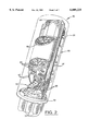
- FIG. 2 is a perspective view of the splice closure according to the invention with the housing shown in dotted outline form, and with only several of the drop or second splice organizer trays in the series shown in detail, the others being schematically represented by the dashed line.
- FIG. 3 is a perspective view of the slack storage tray of the closure as shown in FIG. 2.
- FIG. 4 is a perspective view of the slack storage tray and main or first fiber splice organizer trays of the splice closure as shown in FIG. 2.
- FIG. 5 is a greatly enlarged plan view of a second splice organizer tray used in the splice closure as shown in FIG. 2.
- FIG. 6 is the plan view of the second splice organizer tray as shown in FIG. 5 with one fiber loop shown routed therein.
- FIG. 7 is the plan view of the second splice organizer tray as shown in FIG. 5 with a drop splice shown therein.
- the network 20 illustratively includes a 96-fiber cable 26 which extends in a ring configuration in East and West directions from a telephone company central office 23, as will be readily appreciated by those skilled in the art.
- a plurality of drop locations are positioned along the cable route, such as for various relatively large users or subscribers.
- a splice closure 25 is positioned and connected to the main fiber optic cable 26.
- a pair of drop cables 27 are also connected to the splice closure as will be described in greater detail below.
- the cables 26, 27 are designated A and B to indicate their direction around the ring as will also be readily appreciated by those skilled in the art.
- a single drop cable may also be used, but may provide less reliability than the two drop cable configuration.
- the splice closure 25 includes a generally cylindrical housing 31 indicated in phantom lines in FIG. 2, and a base 32 connected thereto.
- the housing 31 and base 32 may be formed of conventional rugged plastic materials as will be readily appreciated by those skilled in the art.
- a mounting bracket, generally designated at 33, is connected to the base 32.
- a plurality of cable ports 34 extend outwardly from the base 33 to receive respective fiber optic cables as will also be readily appreciated by those skilled in the art.
- the splice closure 25 includes at least one first or main cable splice organizer tray 37 (FIG. 4) having one end pivotally connected to the base 32 via the bracket 33.
- the splice closure 25 includes three such first splice organizer trays 37. Typical configurations may range from one to three, although those of skill in the art will appreciate that more than three may also be provided for high fiber count cables, for example.
- the number of first splice trays 37 if decreased, could allow for a larger slack storage tray 50, for example.
- the first organizer trays 37 are generally rectangular and elongate, and the trays are positioned to extend in a medial portion of a housing.
- the first organizer trays 37 are pivotally connected at one end to the bracket 33.
- the first organizer tray 37 includes a splice support portion 38 for holding or supporting optical fiber splices 40 as will be readily appreciated by those skilled in the art. For a typical configuration, thirty six fibers could be handled by one first splice organizer tray 37.
- the first splice trays 37 include a planar base 42, opposing sidewalls 41a, 41b extending upwardly from the base, and a proximal end including openings 45 to facilitate securing buffer tubes 46 and transport tubes 47.
- buffer tubes refers to the buffer tubes in a typical loose-buffer tube fiber cable
- transport tubes refers to the protective tubes positioned over the individual one or more fibers for routing between trays as will be further described below.
- the first organizer tray 37 also includes a distal end wall 41c and a series of inwardly extending tabs 42 positioned in spaced apart relation on the sidewalls 41a, 41b.
- the planar base, wall portions, and tabs define guide means for routing the optical fibers on the tray without exceeding a minimum bend radius for the fibers as will be readily appreciated by those skilled in the art.
- the first splice organizer trays 37 are pivotally connected to the bracket 33 in a stair-step arrangement to permit access to underlying trays as will also be readily appreciated by those skilled in the art.
- the splice closure 25 also includes a slack storage tray 50 (FIG. 3) connected to the base 32 and positioned in the housing 31 adjacent an underside of first splice trays 37.
- the slack storage tray 50 may be used to store buffer tubes 46 that are not accessed at the drop location, for example.
- the slack tray or basket 50 includes a planar base 51, a first pair of opposing sidewall portions 52a, 52b extending at outwardly diverging angles from the base, and an upper pair of generally parallel sidewall portions 53a, 53b connected to the diverging sidewall portions. Inwardly extending tabs 54 are provided to help retain the buffer tubes 46 in the tray.
- a distal end wall portion 52c is also illustratively provided and connected to the base 51.
- Plastic tie wraps 56 are illustratively used to secure the slack buffer tubes 46 in position.
- the splice closure 25 also includes a mounting member 60 pivotally connected to the base 32 via the bracket 33, and overlying the uppermost first splice organizer tray 37.
- the mounting member 60 in the illustrated embodiment is in the form of a generally rectangular planar member adapted to carry the illustrated plurality of second splice organizer trays 65.
- the mounting member 60 may also include portions for routing and securing buffer/transport tubes, as well as individual fibers.
- the second or drop splice organizers 65 include a pair of hinge pins 66 (FIG. 5) which cooperate with mating recesses in the mounting member 60 to pivotally mount the second trays. Accordingly, the second splice organizer trays 65 may also be pivoted to permit access to a particular tray as will be readily understood by those skilled in the art.
- the second splice trays define respective first pivot axes that are parallel to the second pivot axes of the first splice trays 37.
- the first and second axes are transverse to the longitudinal axis defined by the cylindrical housing 31.
- the mounting member 60 also has a pivot axis transverse to the longitudinal axis of the housing 31, and parallel to the first and second axes of the first and second splice organizer trays.
- the second or drop splice trays 65 are pivotally connected to the mounting member 60 on a side thereof opposite the first splice organizer trays 37.
- the second splice trays 65 are arranged in side-by-side relation.
- the number of such slice trays 65 may be as few as one to as many as twenty-four, for example, as will be appreciated by those skilled in the art. Greater numbers could also be accommodated.
- the splice closure 25 thus provides a compact, yet flexible, closure facilitating drops to a fiber optic ring network 20 as shown in FIG. 1.
- a relatively high density of splices can be accommodated and with partitioning to greatly increase ease of installation and later reconfiguration flexibility.
- the second splice tray 65 may have a rounded free or outer end 65 as illustrated.
- a fiber splice support area 67 may be provided adjacent the free end to hold one or more optical fiber splices as will be readily appreciated by those skilled in the art.
- the shape of the rounded outer end 68 corresponds to the adjacent interior wall portions of the housing 31 to thereby increase the compactness of the splice closure 25.
- one or more optical fiber loops 70 preferably extend from a first splice organizer tray 37 to a predetermined one of the second splice organizer trays to facilitate connecting to the fiber optic cable ring.
- the fiber loop 70 would typically be routed from a second tray 65 a first tray 37.
- the installer would then connect predetermined fibers from the main cable 26 (FIG. 1) to the ends of the loop 71 on the first tray 36.
- forty-eight loops would be provided to permit fibers 1-48 to be available to be dropped by connection at the second splice trays 65.
- the second splice organizer trays 65 each preferably includes fiber guide means for guiding at least one optical fiber.
- the second splice organizer tray 65 comprises the hinge pins 66 defining a hinge portion or end 71 opposite the free end portion 68 and pivotally connected to the mounting member 60.
- the fiber guide means is provided by a horizontal base 77, vertically extending exterior sidewalls 72, interior sidewalls 73, and horizontally extending tabs 74. Paired horizontal tabs 75 define a slotted opening 76 therebetween that can be used to position the fibers under the tabs.
- Those of skill in the art will appreciate that other similar structures may be provided to guide the fibers so that their minimum bend radius is not violated.
- the guide means also define respective first and second optical fiber ports 80, 81 on opposite sides of the hinge portion 71. As shown in FIG. 6, the guide means cooperate so that the loop 70 from a first splice tray 37 can be routed into and out of the port 80. Accordingly, organization of fibers is simplified as, for example, all of the fibers from the first trays 37 can be fed to a common side of the second trays 65. In addition, as will be explained below with reference to FIG. 7, the fibers to the drop cable can be arranged to enter from the opposite port 81 to also facilitate a tidy and efficient routing of fibers as will be readily appreciated by those skilled in the art.
- the fiber loop 70 is routed from the port 80 along the left sidewall 72, along the interior sidewall 73, along the right sidewall 72, along a portion of the bottom sidewall, and up and through the illustrated crossing guide member 85.
- the crossing guide member 85 includes four body portions 85a-85d that define crossing fiber channels through a central portion of the tray to permit the fibers to change rotational directions.
- the body portions 85a-85d define rounded outer surfaces for contacting the fibers routed thereover.
- Horizontally extending tabs 86 are also provided to help retain the fibers.
- each second splice organizer tray 65 can typically hold more than one fiber; however, for clarity of explanation only a single fiber loop 70 is shown in FIG. 6.
- FIG. 7 a second splice organizer tray 65 is shown after the loop fiber 70 has been cut, and a splice 88 has been made to a drop optical fiber 90.
- a splice 88 has been made to a drop optical fiber 90.
- the fiber 70 which is spliced to the main cable at a first splice organizer 37 extends through the left port 80, and the fiber 90 to the drop cable extends through the right port 81 in the illustrated embodiment.
- One slack loop for each fiber is also shown, although multiple such slack loops can be accommodated.
- the invention advantageously, provides at least one third splice organizer tray.
- a tray preferably has the same configuration as the second splice trays 65 described in detail above.
- the third splice tray may be a designated one from the series as shown in FIG. 2, or may be positioned in spaced relation on the mounting member to more readily permit the technician to recognize its different function.
- the third splice organizer tray can permit splicing into any of the fibers in the cable, to thereby provide enhanced flexibility for reconfiguring the network 20 as will be readily appreciated by those skilled in the art.
- a method aspect of the invention is for making a fiber optic cable network 20 of a type comprising a fiber optic cable 26 routed in a ring configuration and a plurality of drop locations along the fiber optic cable route.
- the method preferably comprises the steps of: providing a respective fiber optic splice closure 25 as described in detail above, at each of the drop locations; and splicing the at least one optical fiber from the ring to the at least one optical fiber at the at least one first splice organizer tray 37.
- the method may also include the of splicing at least one optical fiber from a drop cable 27 to the at least one optical fiber loop 70 on the at least one second splice organizer tray 65.
- Each fiber optic splice closure 25 may further comprise a slack storage tray 50 connected to the base 32 and positioned in the housing 31 adjacent a side of the at least one first splice tray 37 opposite the mounting member 60. Accordingly, the method may further include the step of storing slack fiber passing through the splice closure 25 in the slack storage tray 50.
- Another advantageous method feature of the invention permits connection to any of the fibers in the cable ring 26. More particularly, the method may include the steps of providing at least one third splice organizer tray on the mounting member 60, and connecting at least one predetermined optical fiber to the ring using the at least one third splice organizer tray.
Abstract
Description
Claims (50)
Priority Applications (5)
| Application Number | Priority Date | Filing Date | Title |
|---|---|---|---|
| US09/084,182 US6009225A (en) | 1998-05-26 | 1998-05-26 | Fiber optic drop splice closure and related methods |
| AU63812/99A AU6381299A (en) | 1998-05-26 | 1999-05-25 | Fiber optic drop splice closure and related methods |
| PCT/US1999/011456 WO1999067670A2 (en) | 1998-05-26 | 1999-05-25 | Fiber optic drop splice closure and related methods |
| TW088108634A TW445385B (en) | 1998-05-26 | 1999-05-26 | Fiber optic splice closure, fiber optic cable network, and method for making the fiber optic cable network |
| ZA9903558A ZA993558B (en) | 1998-05-26 | 1999-05-26 | Fiber optic drop splice closure and related methods. |
Applications Claiming Priority (1)
| Application Number | Priority Date | Filing Date | Title |
|---|---|---|---|
| US09/084,182 US6009225A (en) | 1998-05-26 | 1998-05-26 | Fiber optic drop splice closure and related methods |
Publications (1)
| Publication Number | Publication Date |
|---|---|
| US6009225A true US6009225A (en) | 1999-12-28 |
Family
ID=22183364
Family Applications (1)
| Application Number | Title | Priority Date | Filing Date |
|---|---|---|---|
| US09/084,182 Expired - Lifetime US6009225A (en) | 1998-05-26 | 1998-05-26 | Fiber optic drop splice closure and related methods |
Country Status (5)
| Country | Link |
|---|---|
| US (1) | US6009225A (en) |
| AU (1) | AU6381299A (en) |
| TW (1) | TW445385B (en) |
| WO (1) | WO1999067670A2 (en) |
| ZA (1) | ZA993558B (en) |
Cited By (72)
| Publication number | Priority date | Publication date | Assignee | Title |
|---|---|---|---|---|
| US6434313B1 (en) * | 2000-10-31 | 2002-08-13 | Corning Cable Systems Llc | Fiber optic closure with couplers and splice tray |
| US20020150372A1 (en) * | 2001-02-12 | 2002-10-17 | Fiber Optic Network Solutions Corp. | Optical fiber enclosure system |
| US6496641B1 (en) * | 1999-08-12 | 2002-12-17 | Bellsouth Intellectual Property Corporation | Fiber optic interface device |
| US20030103750A1 (en) * | 2001-11-30 | 2003-06-05 | Laporte Richard B. | Distribution terminal for network access point |
| US6674952B2 (en) | 2001-04-30 | 2004-01-06 | Telect, Inc. | Fiber optic cable bend radius protection system |
| WO2004051337A1 (en) * | 2002-11-26 | 2004-06-17 | Ccs Technology, Inc. | Device for the structured storage or handling of optical waveguides |
| US6944387B2 (en) | 2001-04-30 | 2005-09-13 | Telect, Inc. | Fiber optic connector tray system |
| US20060215980A1 (en) * | 2005-03-24 | 2006-09-28 | Yilmaz Bayazit | Splice tray arrangement |
| US20070047891A1 (en) * | 2005-08-25 | 2007-03-01 | Yilmaz Bayazit | Stackable splice chip device |
| US20070047892A1 (en) * | 2005-08-25 | 2007-03-01 | Yilmaz Bayazit | Splice chip device |
| US20070104447A1 (en) * | 2005-10-24 | 2007-05-10 | Allen Barry W | Fiber optic splice storage apparatus and methods for using the same |
| US20070104448A1 (en) * | 2005-10-24 | 2007-05-10 | Tyco Electronics Corporation | Optical fiber clips, random access management systems including clips and methods for using the same |
| US20070117825A1 (en) * | 2002-06-17 | 2007-05-24 | Vicuron Pharmaceuticals , Inc. | Use of amide derivative of ge 2270 factor a3 for the treatment of acne |
| US20070172192A1 (en) * | 2005-12-02 | 2007-07-26 | Adc Telecommunications, Inc. | Splice tray arrangement |
| CN100370294C (en) * | 2002-11-26 | 2008-02-20 | Ccs技术公司 | Device for the structured storage or handling of optical waveguides |
| US20080112680A1 (en) * | 2006-11-09 | 2008-05-15 | Mcgranahan Danny | Optical fiber slack storage for splice trays and splice assemblies |
| US20090060428A1 (en) * | 2007-08-27 | 2009-03-05 | Julian Mullaney | Methods for Accessing a Fiber Within a Fiber Optic Cable to Splice Thereto and Tools for Use with the Same |
| US7822310B2 (en) * | 2007-02-28 | 2010-10-26 | Corning Cable Systems Llc | Fiber optic splice trays |
| US7889961B2 (en) | 2008-03-27 | 2011-02-15 | Corning Cable Systems Llc | Compact, high-density adapter module, housing assembly and frame assembly for optical fiber telecommunications |
| US20110164854A1 (en) * | 2008-09-23 | 2011-07-07 | Christophe Desard | Fiber distribution enclosure with extractable organizer |
| US8433171B2 (en) | 2009-06-19 | 2013-04-30 | Corning Cable Systems Llc | High fiber optic cable packing density apparatus |
| US8467651B2 (en) | 2009-09-30 | 2013-06-18 | Ccs Technology Inc. | Fiber optic terminals configured to dispose a fiber optic connection panel(s) within an optical fiber perimeter and related methods |
| US8520996B2 (en) | 2009-03-31 | 2013-08-27 | Corning Cable Systems Llc | Removably mountable fiber optic terminal |
| US8538226B2 (en) | 2009-05-21 | 2013-09-17 | Corning Cable Systems Llc | Fiber optic equipment guides and rails configured with stopping position(s), and related equipment and methods |
| US8542973B2 (en) | 2010-04-23 | 2013-09-24 | Ccs Technology, Inc. | Fiber optic distribution device |
| US8593828B2 (en) | 2010-02-04 | 2013-11-26 | Corning Cable Systems Llc | Communications equipment housings, assemblies, and related alignment features and methods |
| US8625950B2 (en) | 2009-12-18 | 2014-01-07 | Corning Cable Systems Llc | Rotary locking apparatus for fiber optic equipment trays and related methods |
| US8660397B2 (en) | 2010-04-30 | 2014-02-25 | Corning Cable Systems Llc | Multi-layer module |
| US8662760B2 (en) | 2010-10-29 | 2014-03-04 | Corning Cable Systems Llc | Fiber optic connector employing optical fiber guide member |
| US8687934B2 (en) | 2011-03-21 | 2014-04-01 | Tyco Electronics Corporation | Fiber optic component holders and enclosures and methods including the same |
| US8699838B2 (en) | 2009-05-14 | 2014-04-15 | Ccs Technology, Inc. | Fiber optic furcation module |
| US8705926B2 (en) | 2010-04-30 | 2014-04-22 | Corning Optical Communications LLC | Fiber optic housings having a removable top, and related components and methods |
| US8712206B2 (en) | 2009-06-19 | 2014-04-29 | Corning Cable Systems Llc | High-density fiber optic modules and module housings and related equipment |
| US20140119704A1 (en) * | 2012-10-26 | 2014-05-01 | Ccs Technology Inc. | Fiber optic management unit and fiber optic distribution device |
| US8718436B2 (en) | 2010-08-30 | 2014-05-06 | Corning Cable Systems Llc | Methods, apparatuses for providing secure fiber optic connections |
| US8792767B2 (en) | 2010-04-16 | 2014-07-29 | Ccs Technology, Inc. | Distribution device |
| US8798427B2 (en) | 2007-09-05 | 2014-08-05 | Corning Cable Systems Llc | Fiber optic terminal assembly |
| US8879882B2 (en) | 2008-10-27 | 2014-11-04 | Corning Cable Systems Llc | Variably configurable and modular local convergence point |
| US8879881B2 (en) | 2010-04-30 | 2014-11-04 | Corning Cable Systems Llc | Rotatable routing guide and assembly |
| US8909019B2 (en) | 2012-10-11 | 2014-12-09 | Ccs Technology, Inc. | System comprising a plurality of distribution devices and distribution device |
| US8913866B2 (en) | 2010-03-26 | 2014-12-16 | Corning Cable Systems Llc | Movable adapter panel |
| US8953924B2 (en) | 2011-09-02 | 2015-02-10 | Corning Cable Systems Llc | Removable strain relief brackets for securing fiber optic cables and/or optical fibers to fiber optic equipment, and related assemblies and methods |
| US8989547B2 (en) | 2011-06-30 | 2015-03-24 | Corning Cable Systems Llc | Fiber optic equipment assemblies employing non-U-width-sized housings and related methods |
| US8985862B2 (en) | 2013-02-28 | 2015-03-24 | Corning Cable Systems Llc | High-density multi-fiber adapter housings |
| US9008485B2 (en) | 2011-05-09 | 2015-04-14 | Corning Cable Systems Llc | Attachment mechanisms employed to attach a rear housing section to a fiber optic housing, and related assemblies and methods |
| US9004778B2 (en) | 2012-06-29 | 2015-04-14 | Corning Cable Systems Llc | Indexable optical fiber connectors and optical fiber connector arrays |
| US9020320B2 (en) | 2008-08-29 | 2015-04-28 | Corning Cable Systems Llc | High density and bandwidth fiber optic apparatuses and related equipment and methods |
| US9022814B2 (en) | 2010-04-16 | 2015-05-05 | Ccs Technology, Inc. | Sealing and strain relief device for data cables |
| US9042702B2 (en) | 2012-09-18 | 2015-05-26 | Corning Cable Systems Llc | Platforms and systems for fiber optic cable attachment |
| US9038832B2 (en) | 2011-11-30 | 2015-05-26 | Corning Cable Systems Llc | Adapter panel support assembly |
| US9049500B2 (en) | 2012-08-31 | 2015-06-02 | Corning Cable Systems Llc | Fiber optic terminals, systems, and methods for network service management |
| US9059578B2 (en) | 2009-02-24 | 2015-06-16 | Ccs Technology, Inc. | Holding device for a cable or an assembly for use with a cable |
| US9075216B2 (en) | 2009-05-21 | 2015-07-07 | Corning Cable Systems Llc | Fiber optic housings configured to accommodate fiber optic modules/cassettes and fiber optic panels, and related components and methods |
| US9075217B2 (en) | 2010-04-30 | 2015-07-07 | Corning Cable Systems Llc | Apparatuses and related components and methods for expanding capacity of fiber optic housings |
| US9213161B2 (en) | 2010-11-05 | 2015-12-15 | Corning Cable Systems Llc | Fiber body holder and strain relief device |
| US9219546B2 (en) | 2011-12-12 | 2015-12-22 | Corning Optical Communications LLC | Extremely high frequency (EHF) distributed antenna systems, and related components and methods |
| US9250409B2 (en) | 2012-07-02 | 2016-02-02 | Corning Cable Systems Llc | Fiber-optic-module trays and drawers for fiber-optic equipment |
| US9279951B2 (en) | 2010-10-27 | 2016-03-08 | Corning Cable Systems Llc | Fiber optic module for limited space applications having a partially sealed module sub-assembly |
| US9323020B2 (en) | 2008-10-09 | 2016-04-26 | Corning Cable Systems (Shanghai) Co. Ltd | Fiber optic terminal having adapter panel supporting both input and output fibers from an optical splitter |
| US9519118B2 (en) | 2010-04-30 | 2016-12-13 | Corning Optical Communications LLC | Removable fiber management sections for fiber optic housings, and related components and methods |
| US9547144B2 (en) | 2010-03-16 | 2017-01-17 | Corning Optical Communications LLC | Fiber optic distribution network for multiple dwelling units |
| US9547145B2 (en) | 2010-10-19 | 2017-01-17 | Corning Optical Communications LLC | Local convergence point for multiple dwelling unit fiber optic distribution network |
| US9632270B2 (en) | 2010-04-30 | 2017-04-25 | Corning Optical Communications LLC | Fiber optic housings configured for tool-less assembly, and related components and methods |
| US9645317B2 (en) | 2011-02-02 | 2017-05-09 | Corning Optical Communications LLC | Optical backplane extension modules, and related assemblies suitable for establishing optical connections to information processing modules disposed in equipment racks |
| US9720195B2 (en) | 2010-04-30 | 2017-08-01 | Corning Optical Communications LLC | Apparatuses and related components and methods for attachment and release of fiber optic housings to and from an equipment rack |
| US9791653B2 (en) | 2012-04-03 | 2017-10-17 | CommScope Connectivity Belgium BVBA | Telecommunications enclosure organizer |
| US9829665B1 (en) | 2017-04-27 | 2017-11-28 | Afl Telecommunications Llc | Fiber optic splice enclosures |
| US20180129005A1 (en) * | 2016-11-08 | 2018-05-10 | Ortronics, Inc. | Splice Managers and Related Methods of Use |
| US10094996B2 (en) | 2008-08-29 | 2018-10-09 | Corning Optical Communications, Llc | Independently translatable modules and fiber optic equipment trays in fiber optic equipment |
| US10110307B2 (en) | 2012-03-02 | 2018-10-23 | Corning Optical Communications LLC | Optical network units (ONUs) for high bandwidth connectivity, and related components and methods |
| US10310207B2 (en) * | 2015-11-25 | 2019-06-04 | CommScope Connectivity Belgium, BVBA | Fiber management for pivotable trays having fiber guides spaced apart from hinges |
| US11294135B2 (en) | 2008-08-29 | 2022-04-05 | Corning Optical Communications LLC | High density and bandwidth fiber optic apparatuses and related equipment and methods |
Families Citing this family (5)
| Publication number | Priority date | Publication date | Assignee | Title |
|---|---|---|---|---|
| DE102007010863B4 (en) * | 2007-03-01 | 2009-01-08 | Adc Gmbh | Sleeve for fiber optic cable |
| DE102007032186A1 (en) * | 2007-03-01 | 2008-12-18 | Adc Gmbh | Support system for fastening fiber optic telecommunications and data equipment, includes profile terminated by specially-shaped U- and V-sections at its ends |
| DE102007010853B4 (en) | 2007-03-01 | 2009-01-29 | Adc Gmbh | Distributor device for optical waveguides |
| EP2490058A1 (en) * | 2011-02-17 | 2012-08-22 | Tyco Electronics Raychem BVBA | Optical fiber organizer with trays mounted on pivoting support |
| AU2013389185B2 (en) * | 2013-05-08 | 2018-04-05 | Prysmian S.P.A. | Optical joint closure |
Citations (20)
| Publication number | Priority date | Publication date | Assignee | Title |
|---|---|---|---|---|
| US4927227A (en) * | 1988-10-31 | 1990-05-22 | At&T Bell Laboratories | Optical fiber cable closure |
| US5071211A (en) * | 1988-12-20 | 1991-12-10 | Northern Telecom Limited | Connector holders and distribution frame and connector holder assemblies for optical cable |
| US5155794A (en) * | 1984-04-11 | 1992-10-13 | Raychem Corporation | Electrofit fibre optics butt splice |
| US5167001A (en) * | 1991-09-03 | 1992-11-24 | Northern Telecom Limited | Optical fiber storage and connector tray and shelf and tray assembly |
| US5185845A (en) * | 1990-12-13 | 1993-02-09 | At&T Bell Laboratories | Optical fiber closure having enhanced storage capability |
| US5278933A (en) * | 1992-06-30 | 1994-01-11 | Hunsinger Terrance D | Fiber optic splice organizer and associated method |
| US5323480A (en) * | 1992-11-25 | 1994-06-21 | Raychem Corporation | Fiber optic splice closure |
| US5323478A (en) * | 1992-02-21 | 1994-06-21 | Mars Actel | Assembly of stacked and hinged modules |
| US5353366A (en) * | 1993-10-05 | 1994-10-04 | Minnesota Mining And Manufacturing Company | Optical fiber splicing station |
| US5375185A (en) * | 1993-04-30 | 1994-12-20 | Keptel, Inc. | Apparatus for storing and organizing spliced optical fibers |
| US5457763A (en) * | 1989-06-02 | 1995-10-10 | British Telecommunications Public Limited Company | Optical fiber splice organizer |
| US5509099A (en) * | 1995-04-26 | 1996-04-16 | Antec Corp. | Optical fiber closure with sealed cable entry ports |
| US5553186A (en) * | 1995-03-31 | 1996-09-03 | Minnesota Mining And Manufacturing Company | Fiber optic dome closure |
| US5590234A (en) * | 1995-03-31 | 1996-12-31 | Minnesota Mining And Manufacturing Company | Fiber optic splice organizers |
| US5596670A (en) * | 1993-12-09 | 1997-01-21 | Northern Telecom Limited | Optical fiber cable enclosure |
| US5617501A (en) * | 1995-03-31 | 1997-04-01 | Minnesota Mining And Manufacturing Company | Shield bond strain connector for fiber optic closure |
| US5619608A (en) * | 1993-02-04 | 1997-04-08 | Bowthorpe Plc | Optical fibre splice enclosures |
| US5631993A (en) * | 1995-04-20 | 1997-05-20 | Preformed Line Products Company | Optical fiber splice case |
| US5689605A (en) * | 1995-02-09 | 1997-11-18 | Lucent Technologies Inc. | Splice holder assembly for an optical fiber cable splice closure |
| US5717811A (en) * | 1993-09-08 | 1998-02-10 | N.V. Rachem S.A. | Optical fiber organizer |
Family Cites Families (3)
| Publication number | Priority date | Publication date | Assignee | Title |
|---|---|---|---|---|
| GB8729952D0 (en) * | 1987-12-23 | 1988-02-03 | British Telecomm | Mounting assembly for optical equipment |
| ID16057A (en) * | 1996-02-29 | 1997-08-28 | Rauchem Sa Nv | OPTICAL FIBER OR ARRANGEMENT |
| US5734776A (en) * | 1996-08-28 | 1998-03-31 | Adc Telecommunications, Inc. | Outside plant cross-connect apparatus |
-
1998
- 1998-05-26 US US09/084,182 patent/US6009225A/en not_active Expired - Lifetime
-
1999
- 1999-05-25 AU AU63812/99A patent/AU6381299A/en not_active Abandoned
- 1999-05-25 WO PCT/US1999/011456 patent/WO1999067670A2/en active Application Filing
- 1999-05-26 TW TW088108634A patent/TW445385B/en active
- 1999-05-26 ZA ZA9903558A patent/ZA993558B/en unknown
Patent Citations (21)
| Publication number | Priority date | Publication date | Assignee | Title |
|---|---|---|---|---|
| US5155794A (en) * | 1984-04-11 | 1992-10-13 | Raychem Corporation | Electrofit fibre optics butt splice |
| US4927227A (en) * | 1988-10-31 | 1990-05-22 | At&T Bell Laboratories | Optical fiber cable closure |
| US5071211A (en) * | 1988-12-20 | 1991-12-10 | Northern Telecom Limited | Connector holders and distribution frame and connector holder assemblies for optical cable |
| US5457763A (en) * | 1989-06-02 | 1995-10-10 | British Telecommunications Public Limited Company | Optical fiber splice organizer |
| US5185845A (en) * | 1990-12-13 | 1993-02-09 | At&T Bell Laboratories | Optical fiber closure having enhanced storage capability |
| US5167001A (en) * | 1991-09-03 | 1992-11-24 | Northern Telecom Limited | Optical fiber storage and connector tray and shelf and tray assembly |
| US5323478A (en) * | 1992-02-21 | 1994-06-21 | Mars Actel | Assembly of stacked and hinged modules |
| US5278933A (en) * | 1992-06-30 | 1994-01-11 | Hunsinger Terrance D | Fiber optic splice organizer and associated method |
| US5323480A (en) * | 1992-11-25 | 1994-06-21 | Raychem Corporation | Fiber optic splice closure |
| US5515472A (en) * | 1992-11-25 | 1996-05-07 | Raychem Corporation | Fiber optic splice holder |
| US5619608A (en) * | 1993-02-04 | 1997-04-08 | Bowthorpe Plc | Optical fibre splice enclosures |
| US5375185A (en) * | 1993-04-30 | 1994-12-20 | Keptel, Inc. | Apparatus for storing and organizing spliced optical fibers |
| US5717811A (en) * | 1993-09-08 | 1998-02-10 | N.V. Rachem S.A. | Optical fiber organizer |
| US5353366A (en) * | 1993-10-05 | 1994-10-04 | Minnesota Mining And Manufacturing Company | Optical fiber splicing station |
| US5596670A (en) * | 1993-12-09 | 1997-01-21 | Northern Telecom Limited | Optical fiber cable enclosure |
| US5689605A (en) * | 1995-02-09 | 1997-11-18 | Lucent Technologies Inc. | Splice holder assembly for an optical fiber cable splice closure |
| US5590234A (en) * | 1995-03-31 | 1996-12-31 | Minnesota Mining And Manufacturing Company | Fiber optic splice organizers |
| US5617501A (en) * | 1995-03-31 | 1997-04-01 | Minnesota Mining And Manufacturing Company | Shield bond strain connector for fiber optic closure |
| US5553186A (en) * | 1995-03-31 | 1996-09-03 | Minnesota Mining And Manufacturing Company | Fiber optic dome closure |
| US5631993A (en) * | 1995-04-20 | 1997-05-20 | Preformed Line Products Company | Optical fiber splice case |
| US5509099A (en) * | 1995-04-26 | 1996-04-16 | Antec Corp. | Optical fiber closure with sealed cable entry ports |
Cited By (128)
| Publication number | Priority date | Publication date | Assignee | Title |
|---|---|---|---|---|
| US6496641B1 (en) * | 1999-08-12 | 2002-12-17 | Bellsouth Intellectual Property Corporation | Fiber optic interface device |
| US6625375B1 (en) * | 1999-08-12 | 2003-09-23 | Bellsouth Intellectual Property Corporation | Fiber optic interface device |
| US6434313B1 (en) * | 2000-10-31 | 2002-08-13 | Corning Cable Systems Llc | Fiber optic closure with couplers and splice tray |
| US7068907B2 (en) | 2001-02-12 | 2006-06-27 | Fiber Optic Network Solutions, Corp. | Optical fiber enclosure system |
| US20020150372A1 (en) * | 2001-02-12 | 2002-10-17 | Fiber Optic Network Solutions Corp. | Optical fiber enclosure system |
| US6845207B2 (en) * | 2001-02-12 | 2005-01-18 | Fiber Optic Network Solutions Corp. | Optical fiber enclosure system |
| US20050100302A1 (en) * | 2001-02-12 | 2005-05-12 | Fiber Optic Network Solutions Corp. | Optical fiber enclosure system |
| US6674952B2 (en) | 2001-04-30 | 2004-01-06 | Telect, Inc. | Fiber optic cable bend radius protection system |
| US6944387B2 (en) | 2001-04-30 | 2005-09-13 | Telect, Inc. | Fiber optic connector tray system |
| US20030103750A1 (en) * | 2001-11-30 | 2003-06-05 | Laporte Richard B. | Distribution terminal for network access point |
| US6621975B2 (en) * | 2001-11-30 | 2003-09-16 | Corning Cable Systems Llc | Distribution terminal for network access point |
| US20070117825A1 (en) * | 2002-06-17 | 2007-05-24 | Vicuron Pharmaceuticals , Inc. | Use of amide derivative of ge 2270 factor a3 for the treatment of acne |
| US7302151B2 (en) | 2002-11-26 | 2007-11-27 | Corning Cable Systems Llc | Device for the structured storage or handling of optical waveguides |
| US20060029351A1 (en) * | 2002-11-26 | 2006-02-09 | Oliver Lapp | Device for the structured storage or handling of optical waveguides |
| EP1921479A1 (en) * | 2002-11-26 | 2008-05-14 | CCS Technology, Inc. | Device for the structured storage or handling of optical waveguides |
| CN100370294C (en) * | 2002-11-26 | 2008-02-20 | Ccs技术公司 | Device for the structured storage or handling of optical waveguides |
| WO2004051337A1 (en) * | 2002-11-26 | 2004-06-17 | Ccs Technology, Inc. | Device for the structured storage or handling of optical waveguides |
| US20060215980A1 (en) * | 2005-03-24 | 2006-09-28 | Yilmaz Bayazit | Splice tray arrangement |
| US7463810B2 (en) | 2005-08-25 | 2008-12-09 | Adc Telecommunications, Inc. | Splice chip device |
| US20080181569A1 (en) * | 2005-08-25 | 2008-07-31 | Adc Telecommunications, Inc. | Stackable splice chip device |
| US7272291B2 (en) | 2005-08-25 | 2007-09-18 | Adc Telecommunications, Inc. | Splice chip device |
| US7764858B2 (en) | 2005-08-25 | 2010-07-27 | Adc Telecommunications, Inc. | Stackable splice chip device |
| US7684669B2 (en) | 2005-08-25 | 2010-03-23 | Adc Telecommunications, Inc. | Splice chip device |
| US7310471B2 (en) | 2005-08-25 | 2007-12-18 | Adc Telecommunications, Inc. | Stackable splice chip device |
| US20070047892A1 (en) * | 2005-08-25 | 2007-03-01 | Yilmaz Bayazit | Splice chip device |
| US7421182B2 (en) | 2005-08-25 | 2008-09-02 | Adc Telecommunications, Inc. | Stackable splice chip device |
| US20070047891A1 (en) * | 2005-08-25 | 2007-03-01 | Yilmaz Bayazit | Stackable splice chip device |
| US20090136185A1 (en) * | 2005-08-25 | 2009-05-28 | Adc Telecommunications, Inc. | Splice chip device |
| US20070104448A1 (en) * | 2005-10-24 | 2007-05-10 | Tyco Electronics Corporation | Optical fiber clips, random access management systems including clips and methods for using the same |
| US7340145B2 (en) | 2005-10-24 | 2008-03-04 | Tyco Electronics Corporation | Fiber optic splice storage apparatus and methods for using the same |
| US7454115B2 (en) | 2005-10-24 | 2008-11-18 | Tyco Electronics Corporation | Optical fiber clips, random access management systems including clips and methods for using the same |
| US20070104447A1 (en) * | 2005-10-24 | 2007-05-10 | Allen Barry W | Fiber optic splice storage apparatus and methods for using the same |
| US20090136195A1 (en) * | 2005-12-02 | 2009-05-28 | Adc Telecommunications, Inc. | Splice tray arrangement |
| US7457504B2 (en) | 2005-12-02 | 2008-11-25 | Adc Telecommunications, Inc. | Splice tray arrangement |
| US7620288B2 (en) | 2005-12-02 | 2009-11-17 | Adc Telecommunications, Inc. | Splice tray arrangement |
| US7274852B1 (en) | 2005-12-02 | 2007-09-25 | Adc Telecommunications, Inc. | Splice tray arrangement |
| US20070172192A1 (en) * | 2005-12-02 | 2007-07-26 | Adc Telecommunications, Inc. | Splice tray arrangement |
| US20080112680A1 (en) * | 2006-11-09 | 2008-05-15 | Mcgranahan Danny | Optical fiber slack storage for splice trays and splice assemblies |
| US7936960B2 (en) | 2006-11-09 | 2011-05-03 | Corning Cable Systems Llc | Optical fiber slack storage for splice trays and splice assemblies |
| US7822310B2 (en) * | 2007-02-28 | 2010-10-26 | Corning Cable Systems Llc | Fiber optic splice trays |
| US20090060428A1 (en) * | 2007-08-27 | 2009-03-05 | Julian Mullaney | Methods for Accessing a Fiber Within a Fiber Optic Cable to Splice Thereto and Tools for Use with the Same |
| US7860364B2 (en) | 2007-08-27 | 2010-12-28 | Tyco Electronics Corporation | Methods for accessing a fiber within a fiber optic cable to splice thereto and tools for use with the same |
| US8798427B2 (en) | 2007-09-05 | 2014-08-05 | Corning Cable Systems Llc | Fiber optic terminal assembly |
| US7889961B2 (en) | 2008-03-27 | 2011-02-15 | Corning Cable Systems Llc | Compact, high-density adapter module, housing assembly and frame assembly for optical fiber telecommunications |
| US10852499B2 (en) | 2008-08-29 | 2020-12-01 | Corning Optical Communications LLC | High density and bandwidth fiber optic apparatuses and related equipment and methods |
| US11294136B2 (en) | 2008-08-29 | 2022-04-05 | Corning Optical Communications LLC | High density and bandwidth fiber optic apparatuses and related equipment and methods |
| US10606014B2 (en) | 2008-08-29 | 2020-03-31 | Corning Optical Communications LLC | Independently translatable modules and fiber optic equipment trays in fiber optic equipment |
| US10120153B2 (en) | 2008-08-29 | 2018-11-06 | Corning Optical Communications, Llc | Independently translatable modules and fiber optic equipment trays in fiber optic equipment |
| US10126514B2 (en) | 2008-08-29 | 2018-11-13 | Corning Optical Communications, Llc | Independently translatable modules and fiber optic equipment trays in fiber optic equipment |
| US11086089B2 (en) | 2008-08-29 | 2021-08-10 | Corning Optical Communications LLC | High density and bandwidth fiber optic apparatuses and related equipment and methods |
| US10459184B2 (en) | 2008-08-29 | 2019-10-29 | Corning Optical Communications LLC | High density and bandwidth fiber optic apparatuses and related equipment and methods |
| US10094996B2 (en) | 2008-08-29 | 2018-10-09 | Corning Optical Communications, Llc | Independently translatable modules and fiber optic equipment trays in fiber optic equipment |
| US10222570B2 (en) | 2008-08-29 | 2019-03-05 | Corning Optical Communications LLC | Independently translatable modules and fiber optic equipment trays in fiber optic equipment |
| US9910236B2 (en) | 2008-08-29 | 2018-03-06 | Corning Optical Communications LLC | High density and bandwidth fiber optic apparatuses and related equipment and methods |
| US9020320B2 (en) | 2008-08-29 | 2015-04-28 | Corning Cable Systems Llc | High density and bandwidth fiber optic apparatuses and related equipment and methods |
| US10416405B2 (en) | 2008-08-29 | 2019-09-17 | Corning Optical Communications LLC | Independently translatable modules and fiber optic equipment trays in fiber optic equipment |
| US11092767B2 (en) | 2008-08-29 | 2021-08-17 | Corning Optical Communications LLC | High density and bandwidth fiber optic apparatuses and related equipment and methods |
| US11754796B2 (en) | 2008-08-29 | 2023-09-12 | Corning Optical Communications LLC | Independently translatable modules and fiber optic equipment trays in fiber optic equipment |
| US10422971B2 (en) | 2008-08-29 | 2019-09-24 | Corning Optical Communicatinos LLC | High density and bandwidth fiber optic apparatuses and related equipment and methods |
| US11294135B2 (en) | 2008-08-29 | 2022-04-05 | Corning Optical Communications LLC | High density and bandwidth fiber optic apparatuses and related equipment and methods |
| US11609396B2 (en) | 2008-08-29 | 2023-03-21 | Corning Optical Communications LLC | High density and bandwidth fiber optic apparatuses and related equipment and methods |
| US10564378B2 (en) | 2008-08-29 | 2020-02-18 | Corning Optical Communications LLC | High density and bandwidth fiber optic apparatuses and related equipment and methods |
| US10444456B2 (en) | 2008-08-29 | 2019-10-15 | Corning Optical Communications LLC | High density and bandwidth fiber optic apparatuses and related equipment and methods |
| US20110164854A1 (en) * | 2008-09-23 | 2011-07-07 | Christophe Desard | Fiber distribution enclosure with extractable organizer |
| US9323020B2 (en) | 2008-10-09 | 2016-04-26 | Corning Cable Systems (Shanghai) Co. Ltd | Fiber optic terminal having adapter panel supporting both input and output fibers from an optical splitter |
| US8879882B2 (en) | 2008-10-27 | 2014-11-04 | Corning Cable Systems Llc | Variably configurable and modular local convergence point |
| US9059578B2 (en) | 2009-02-24 | 2015-06-16 | Ccs Technology, Inc. | Holding device for a cable or an assembly for use with a cable |
| US8520996B2 (en) | 2009-03-31 | 2013-08-27 | Corning Cable Systems Llc | Removably mountable fiber optic terminal |
| US8699838B2 (en) | 2009-05-14 | 2014-04-15 | Ccs Technology, Inc. | Fiber optic furcation module |
| US8538226B2 (en) | 2009-05-21 | 2013-09-17 | Corning Cable Systems Llc | Fiber optic equipment guides and rails configured with stopping position(s), and related equipment and methods |
| US9075216B2 (en) | 2009-05-21 | 2015-07-07 | Corning Cable Systems Llc | Fiber optic housings configured to accommodate fiber optic modules/cassettes and fiber optic panels, and related components and methods |
| US8712206B2 (en) | 2009-06-19 | 2014-04-29 | Corning Cable Systems Llc | High-density fiber optic modules and module housings and related equipment |
| US8433171B2 (en) | 2009-06-19 | 2013-04-30 | Corning Cable Systems Llc | High fiber optic cable packing density apparatus |
| US8467651B2 (en) | 2009-09-30 | 2013-06-18 | Ccs Technology Inc. | Fiber optic terminals configured to dispose a fiber optic connection panel(s) within an optical fiber perimeter and related methods |
| US8625950B2 (en) | 2009-12-18 | 2014-01-07 | Corning Cable Systems Llc | Rotary locking apparatus for fiber optic equipment trays and related methods |
| US8992099B2 (en) | 2010-02-04 | 2015-03-31 | Corning Cable Systems Llc | Optical interface cards, assemblies, and related methods, suited for installation and use in antenna system equipment |
| US8593828B2 (en) | 2010-02-04 | 2013-11-26 | Corning Cable Systems Llc | Communications equipment housings, assemblies, and related alignment features and methods |
| US9547144B2 (en) | 2010-03-16 | 2017-01-17 | Corning Optical Communications LLC | Fiber optic distribution network for multiple dwelling units |
| US8913866B2 (en) | 2010-03-26 | 2014-12-16 | Corning Cable Systems Llc | Movable adapter panel |
| US8792767B2 (en) | 2010-04-16 | 2014-07-29 | Ccs Technology, Inc. | Distribution device |
| US9022814B2 (en) | 2010-04-16 | 2015-05-05 | Ccs Technology, Inc. | Sealing and strain relief device for data cables |
| US8542973B2 (en) | 2010-04-23 | 2013-09-24 | Ccs Technology, Inc. | Fiber optic distribution device |
| US9632270B2 (en) | 2010-04-30 | 2017-04-25 | Corning Optical Communications LLC | Fiber optic housings configured for tool-less assembly, and related components and methods |
| US9075217B2 (en) | 2010-04-30 | 2015-07-07 | Corning Cable Systems Llc | Apparatuses and related components and methods for expanding capacity of fiber optic housings |
| US8660397B2 (en) | 2010-04-30 | 2014-02-25 | Corning Cable Systems Llc | Multi-layer module |
| US8705926B2 (en) | 2010-04-30 | 2014-04-22 | Corning Optical Communications LLC | Fiber optic housings having a removable top, and related components and methods |
| US9519118B2 (en) | 2010-04-30 | 2016-12-13 | Corning Optical Communications LLC | Removable fiber management sections for fiber optic housings, and related components and methods |
| US8879881B2 (en) | 2010-04-30 | 2014-11-04 | Corning Cable Systems Llc | Rotatable routing guide and assembly |
| US9720195B2 (en) | 2010-04-30 | 2017-08-01 | Corning Optical Communications LLC | Apparatuses and related components and methods for attachment and release of fiber optic housings to and from an equipment rack |
| US8718436B2 (en) | 2010-08-30 | 2014-05-06 | Corning Cable Systems Llc | Methods, apparatuses for providing secure fiber optic connections |
| US9720197B2 (en) | 2010-10-19 | 2017-08-01 | Corning Optical Communications LLC | Transition box for multiple dwelling unit fiber optic distribution network |
| US9547145B2 (en) | 2010-10-19 | 2017-01-17 | Corning Optical Communications LLC | Local convergence point for multiple dwelling unit fiber optic distribution network |
| US9279951B2 (en) | 2010-10-27 | 2016-03-08 | Corning Cable Systems Llc | Fiber optic module for limited space applications having a partially sealed module sub-assembly |
| US8662760B2 (en) | 2010-10-29 | 2014-03-04 | Corning Cable Systems Llc | Fiber optic connector employing optical fiber guide member |
| US9213161B2 (en) | 2010-11-05 | 2015-12-15 | Corning Cable Systems Llc | Fiber body holder and strain relief device |
| US9645317B2 (en) | 2011-02-02 | 2017-05-09 | Corning Optical Communications LLC | Optical backplane extension modules, and related assemblies suitable for establishing optical connections to information processing modules disposed in equipment racks |
| US10481335B2 (en) | 2011-02-02 | 2019-11-19 | Corning Optical Communications, Llc | Dense shuttered fiber optic connectors and assemblies suitable for establishing optical connections for optical backplanes in equipment racks |
| US9494765B2 (en) | 2011-03-21 | 2016-11-15 | Commscope Technologies Llc | Fiber optic component holders and enclosures and methods including same |
| US8687934B2 (en) | 2011-03-21 | 2014-04-01 | Tyco Electronics Corporation | Fiber optic component holders and enclosures and methods including the same |
| US9008485B2 (en) | 2011-05-09 | 2015-04-14 | Corning Cable Systems Llc | Attachment mechanisms employed to attach a rear housing section to a fiber optic housing, and related assemblies and methods |
| US8989547B2 (en) | 2011-06-30 | 2015-03-24 | Corning Cable Systems Llc | Fiber optic equipment assemblies employing non-U-width-sized housings and related methods |
| US8953924B2 (en) | 2011-09-02 | 2015-02-10 | Corning Cable Systems Llc | Removable strain relief brackets for securing fiber optic cables and/or optical fibers to fiber optic equipment, and related assemblies and methods |
| US9038832B2 (en) | 2011-11-30 | 2015-05-26 | Corning Cable Systems Llc | Adapter panel support assembly |
| US9219546B2 (en) | 2011-12-12 | 2015-12-22 | Corning Optical Communications LLC | Extremely high frequency (EHF) distributed antenna systems, and related components and methods |
| US10110305B2 (en) | 2011-12-12 | 2018-10-23 | Corning Optical Communications LLC | Extremely high frequency (EHF) distributed antenna systems, and related components and methods |
| US9800339B2 (en) | 2011-12-12 | 2017-10-24 | Corning Optical Communications LLC | Extremely high frequency (EHF) distributed antenna systems, and related components and methods |
| US9602209B2 (en) | 2011-12-12 | 2017-03-21 | Corning Optical Communications LLC | Extremely high frequency (EHF) distributed antenna systems, and related components and methods |
| US10110307B2 (en) | 2012-03-02 | 2018-10-23 | Corning Optical Communications LLC | Optical network units (ONUs) for high bandwidth connectivity, and related components and methods |
| US11747583B2 (en) | 2012-04-03 | 2023-09-05 | CommScope Connectivity Belgium BVBA | Telecommunications enclosure and organizer |
| US11016257B2 (en) | 2012-04-03 | 2021-05-25 | CommScope Connectivity Belgium BVBA | Telecommunications enclosure and organizer |
| US9791653B2 (en) | 2012-04-03 | 2017-10-17 | CommScope Connectivity Belgium BVBA | Telecommunications enclosure organizer |
| US10444455B2 (en) | 2012-04-03 | 2019-10-15 | CommScope Connectivity Belgium BVBA | Telecommunications enclosure and organizer |
| US9004778B2 (en) | 2012-06-29 | 2015-04-14 | Corning Cable Systems Llc | Indexable optical fiber connectors and optical fiber connector arrays |
| US9250409B2 (en) | 2012-07-02 | 2016-02-02 | Corning Cable Systems Llc | Fiber-optic-module trays and drawers for fiber-optic equipment |
| US9049500B2 (en) | 2012-08-31 | 2015-06-02 | Corning Cable Systems Llc | Fiber optic terminals, systems, and methods for network service management |
| US9042702B2 (en) | 2012-09-18 | 2015-05-26 | Corning Cable Systems Llc | Platforms and systems for fiber optic cable attachment |
| US8909019B2 (en) | 2012-10-11 | 2014-12-09 | Ccs Technology, Inc. | System comprising a plurality of distribution devices and distribution device |
| US20140119704A1 (en) * | 2012-10-26 | 2014-05-01 | Ccs Technology Inc. | Fiber optic management unit and fiber optic distribution device |
| US8995812B2 (en) * | 2012-10-26 | 2015-03-31 | Ccs Technology, Inc. | Fiber optic management unit and fiber optic distribution device |
| US8985862B2 (en) | 2013-02-28 | 2015-03-24 | Corning Cable Systems Llc | High-density multi-fiber adapter housings |
| US10310207B2 (en) * | 2015-11-25 | 2019-06-04 | CommScope Connectivity Belgium, BVBA | Fiber management for pivotable trays having fiber guides spaced apart from hinges |
| US10895704B2 (en) | 2015-11-25 | 2021-01-19 | CommScope Connectivity Belgium BVBA | Fiber management for pivotable trays having fiber guides spaced apart from hinges |
| US11385430B2 (en) | 2015-11-25 | 2022-07-12 | CommScope Connectivity Belgium BVBA | Fiber management for pivotable trays having fiber guides spaced apart from hinges |
| US11624887B2 (en) | 2015-11-25 | 2023-04-11 | CommScope Connectivity Belgium BVBA | Fiber management for pivotable trays having fiber guides spaced apart from hinges |
| US20180129005A1 (en) * | 2016-11-08 | 2018-05-10 | Ortronics, Inc. | Splice Managers and Related Methods of Use |
| US10788640B2 (en) * | 2016-11-08 | 2020-09-29 | Ortronics, Inc. | Splice managers and related methods of use |
| US10241287B2 (en) | 2017-04-27 | 2019-03-26 | Afl Telecommunications Llc | Fiber optic splice enclosures |
| US9829665B1 (en) | 2017-04-27 | 2017-11-28 | Afl Telecommunications Llc | Fiber optic splice enclosures |
Also Published As
| Publication number | Publication date |
|---|---|
| WO1999067670A9 (en) | 2000-07-20 |
| WO1999067670A3 (en) | 2000-03-09 |
| WO1999067670A2 (en) | 1999-12-29 |
| TW445385B (en) | 2001-07-11 |
| AU6381299A (en) | 2000-01-10 |
| ZA993558B (en) | 2000-11-27 |
Similar Documents
| Publication | Publication Date | Title |
|---|---|---|
| US6009225A (en) | Fiber optic drop splice closure and related methods | |
| US6621975B2 (en) | Distribution terminal for network access point | |
| JP3819022B2 (en) | Fiber optic organizer | |
| US5751882A (en) | Optical fibre organizer | |
| RU2451957C2 (en) | System for maintenance of fire-optic circuits with splice tray | |
| US6539160B2 (en) | Optical fiber splicing and connecting assembly with coupler cassette | |
| CA2171001C (en) | Optical fibre organizer | |
| KR100326644B1 (en) | Fiber Optic Organizer | |
| US20080279522A1 (en) | Outside plant enclosure with pivoting fiber trays | |
| EP0725938A1 (en) | Break-out tray | |
| CA2169076C (en) | Optical fibre routing mechanism | |
| EP0717861B1 (en) | Optical fibre organizer | |
| EP0756713B1 (en) | Splice tray |
Legal Events
| Date | Code | Title | Description |
|---|---|---|---|
| AS | Assignment |
Owner name: RAYCHEM CORPORATION, NORTH CAROLINA Free format text: ASSIGNMENT OF ASSIGNORS INTEREST;ASSIGNORS:RAY, CRAIG D.;ABERSON, JIM;REEL/FRAME:009318/0993;SIGNING DATES FROM 19980608 TO 19980616 |
|
| STCF | Information on status: patent grant |
Free format text: PATENTED CASE |
|
| AS | Assignment |
Owner name: TYCO INTERNATIONAL LTD., A CORPORATION OF BERMUDA, Free format text: MERGER & REORGANIZATION;ASSIGNOR:RAYCHEM CORPORATION, A CORPORATION OF DELAWARE;REEL/FRAME:011682/0001 Effective date: 19990812 Owner name: AMP INCORPORATED, A CORPORATION OF PENNSYLVANIA, P Free format text: MERGER & REORGANIZATION;ASSIGNOR:RAYCHEM CORPORATION, A CORPORATION OF DELAWARE;REEL/FRAME:011682/0001 Effective date: 19990812 Owner name: TYCO INTERNATIONAL (PA), INC., A CORPORATION OF NE Free format text: MERGER & REORGANIZATION;ASSIGNOR:RAYCHEM CORPORATION, A CORPORATION OF DELAWARE;REEL/FRAME:011682/0001 Effective date: 19990812 |
|
| AS | Assignment |
Owner name: TYCO ELECTRONICS CORPORATION, A CORPORATION OF PEN Free format text: CHANGE OF NAME;ASSIGNOR:AMP INCORPORATED, A CORPORATION OF PENNSYLVANIA;REEL/FRAME:011675/0436 Effective date: 19990913 |
|
| FPAY | Fee payment |
Year of fee payment: 4 |
|
| FPAY | Fee payment |
Year of fee payment: 8 |
|
| FPAY | Fee payment |
Year of fee payment: 12 |
|
| AS | Assignment |
Owner name: TYCO ELECTRONICS SERVICES GMBH, SWITZERLAND Free format text: ASSIGNMENT OF ASSIGNORS INTEREST;ASSIGNOR:TYCO ELECTRONICS CORPORATION;REEL/FRAME:036074/0740 Effective date: 20150410 |
|
| AS | Assignment |
Owner name: COMMSCOPE EMEA LIMITED, IRELAND Free format text: ASSIGNMENT OF ASSIGNORS INTEREST;ASSIGNOR:TYCO ELECTRONICS SERVICES GMBH;REEL/FRAME:036956/0001 Effective date: 20150828 |
|
| AS | Assignment |
Owner name: COMMSCOPE TECHNOLOGIES LLC, NORTH CAROLINA Free format text: ASSIGNMENT OF ASSIGNORS INTEREST;ASSIGNOR:COMMSCOPE EMEA LIMITED;REEL/FRAME:037012/0001 Effective date: 20150828 |
|
| AS | Assignment |
Owner name: JPMORGAN CHASE BANK, N.A., AS COLLATERAL AGENT, ILLINOIS Free format text: PATENT SECURITY AGREEMENT (TERM);ASSIGNOR:COMMSCOPE TECHNOLOGIES LLC;REEL/FRAME:037513/0709 Effective date: 20151220 Owner name: JPMORGAN CHASE BANK, N.A., AS COLLATERAL AGENT, ILLINOIS Free format text: PATENT SECURITY AGREEMENT (ABL);ASSIGNOR:COMMSCOPE TECHNOLOGIES LLC;REEL/FRAME:037514/0196 Effective date: 20151220 Owner name: JPMORGAN CHASE BANK, N.A., AS COLLATERAL AGENT, IL Free format text: PATENT SECURITY AGREEMENT (ABL);ASSIGNOR:COMMSCOPE TECHNOLOGIES LLC;REEL/FRAME:037514/0196 Effective date: 20151220 Owner name: JPMORGAN CHASE BANK, N.A., AS COLLATERAL AGENT, IL Free format text: PATENT SECURITY AGREEMENT (TERM);ASSIGNOR:COMMSCOPE TECHNOLOGIES LLC;REEL/FRAME:037513/0709 Effective date: 20151220 |
|
| AS | Assignment |
Owner name: REDWOOD SYSTEMS, INC., NORTH CAROLINA Free format text: RELEASE BY SECURED PARTY;ASSIGNOR:JPMORGAN CHASE BANK, N.A.;REEL/FRAME:048840/0001 Effective date: 20190404 Owner name: COMMSCOPE TECHNOLOGIES LLC, NORTH CAROLINA Free format text: RELEASE BY SECURED PARTY;ASSIGNOR:JPMORGAN CHASE BANK, N.A.;REEL/FRAME:048840/0001 Effective date: 20190404 Owner name: ALLEN TELECOM LLC, ILLINOIS Free format text: RELEASE BY SECURED PARTY;ASSIGNOR:JPMORGAN CHASE BANK, N.A.;REEL/FRAME:048840/0001 Effective date: 20190404 Owner name: COMMSCOPE, INC. OF NORTH CAROLINA, NORTH CAROLINA Free format text: RELEASE BY SECURED PARTY;ASSIGNOR:JPMORGAN CHASE BANK, N.A.;REEL/FRAME:048840/0001 Effective date: 20190404 Owner name: ANDREW LLC, NORTH CAROLINA Free format text: RELEASE BY SECURED PARTY;ASSIGNOR:JPMORGAN CHASE BANK, N.A.;REEL/FRAME:048840/0001 Effective date: 20190404 Owner name: COMMSCOPE, INC. OF NORTH CAROLINA, NORTH CAROLINA Free format text: RELEASE BY SECURED PARTY;ASSIGNOR:JPMORGAN CHASE BANK, N.A.;REEL/FRAME:049260/0001 Effective date: 20190404 Owner name: COMMSCOPE TECHNOLOGIES LLC, NORTH CAROLINA Free format text: RELEASE BY SECURED PARTY;ASSIGNOR:JPMORGAN CHASE BANK, N.A.;REEL/FRAME:049260/0001 Effective date: 20190404 Owner name: ANDREW LLC, NORTH CAROLINA Free format text: RELEASE BY SECURED PARTY;ASSIGNOR:JPMORGAN CHASE BANK, N.A.;REEL/FRAME:049260/0001 Effective date: 20190404 Owner name: ALLEN TELECOM LLC, ILLINOIS Free format text: RELEASE BY SECURED PARTY;ASSIGNOR:JPMORGAN CHASE BANK, N.A.;REEL/FRAME:049260/0001 Effective date: 20190404 Owner name: REDWOOD SYSTEMS, INC., NORTH CAROLINA Free format text: RELEASE BY SECURED PARTY;ASSIGNOR:JPMORGAN CHASE BANK, N.A.;REEL/FRAME:049260/0001 Effective date: 20190404 |