US6024446A - Eyewear with hingedly attached strapped head retainer - Google Patents
Eyewear with hingedly attached strapped head retainer Download PDFInfo
- Publication number
- US6024446A US6024446A US08/806,595 US80659597A US6024446A US 6024446 A US6024446 A US 6024446A US 80659597 A US80659597 A US 80659597A US 6024446 A US6024446 A US 6024446A
- Authority
- US
- United States
- Prior art keywords
- eyewear
- lens
- end piece
- strap
- recesses
- Prior art date
- Legal status (The legal status is an assumption and is not a legal conclusion. Google has not performed a legal analysis and makes no representation as to the accuracy of the status listed.)
- Expired - Lifetime
Links
Images


Classifications
-
- G—PHYSICS
- G02—OPTICS
- G02C—SPECTACLES; SUNGLASSES OR GOGGLES INSOFAR AS THEY HAVE THE SAME FEATURES AS SPECTACLES; CONTACT LENSES
- G02C5/00—Constructions of non-optical parts
- G02C5/22—Hinges
- G02C5/2263—Composite hinges, e.g. for varying the inclination of the lenses
-
- A—HUMAN NECESSITIES
- A61—MEDICAL OR VETERINARY SCIENCE; HYGIENE
- A61F—FILTERS IMPLANTABLE INTO BLOOD VESSELS; PROSTHESES; DEVICES PROVIDING PATENCY TO, OR PREVENTING COLLAPSING OF, TUBULAR STRUCTURES OF THE BODY, e.g. STENTS; ORTHOPAEDIC, NURSING OR CONTRACEPTIVE DEVICES; FOMENTATION; TREATMENT OR PROTECTION OF EYES OR EARS; BANDAGES, DRESSINGS OR ABSORBENT PADS; FIRST-AID KITS
- A61F11/00—Methods or devices for treatment of the ears or hearing sense; Non-electric hearing aids; Methods or devices for enabling ear patients to achieve auditory perception through physiological senses other than hearing sense; Protective devices for the ears, carried on the body or in the hand
- A61F11/06—Protective devices for the ears
- A61F11/14—Protective devices for the ears external, e.g. earcaps or earmuffs
-
- A—HUMAN NECESSITIES
- A61—MEDICAL OR VETERINARY SCIENCE; HYGIENE
- A61F—FILTERS IMPLANTABLE INTO BLOOD VESSELS; PROSTHESES; DEVICES PROVIDING PATENCY TO, OR PREVENTING COLLAPSING OF, TUBULAR STRUCTURES OF THE BODY, e.g. STENTS; ORTHOPAEDIC, NURSING OR CONTRACEPTIVE DEVICES; FOMENTATION; TREATMENT OR PROTECTION OF EYES OR EARS; BANDAGES, DRESSINGS OR ABSORBENT PADS; FIRST-AID KITS
- A61F9/00—Methods or devices for treatment of the eyes; Devices for putting-in contact lenses; Devices to correct squinting; Apparatus to guide the blind; Protective devices for the eyes, carried on the body or in the hand
- A61F9/02—Goggles
- A61F9/025—Special attachment of screens, e.g. hinged, removable; Roll-up protective layers
-
- A—HUMAN NECESSITIES
- A61—MEDICAL OR VETERINARY SCIENCE; HYGIENE
- A61F—FILTERS IMPLANTABLE INTO BLOOD VESSELS; PROSTHESES; DEVICES PROVIDING PATENCY TO, OR PREVENTING COLLAPSING OF, TUBULAR STRUCTURES OF THE BODY, e.g. STENTS; ORTHOPAEDIC, NURSING OR CONTRACEPTIVE DEVICES; FOMENTATION; TREATMENT OR PROTECTION OF EYES OR EARS; BANDAGES, DRESSINGS OR ABSORBENT PADS; FIRST-AID KITS
- A61F9/00—Methods or devices for treatment of the eyes; Devices for putting-in contact lenses; Devices to correct squinting; Apparatus to guide the blind; Protective devices for the eyes, carried on the body or in the hand
- A61F9/02—Goggles
- A61F9/026—Paddings; Cushions; Fittings to the face
-
- A—HUMAN NECESSITIES
- A61—MEDICAL OR VETERINARY SCIENCE; HYGIENE
- A61F—FILTERS IMPLANTABLE INTO BLOOD VESSELS; PROSTHESES; DEVICES PROVIDING PATENCY TO, OR PREVENTING COLLAPSING OF, TUBULAR STRUCTURES OF THE BODY, e.g. STENTS; ORTHOPAEDIC, NURSING OR CONTRACEPTIVE DEVICES; FOMENTATION; TREATMENT OR PROTECTION OF EYES OR EARS; BANDAGES, DRESSINGS OR ABSORBENT PADS; FIRST-AID KITS
- A61F9/00—Methods or devices for treatment of the eyes; Devices for putting-in contact lenses; Devices to correct squinting; Apparatus to guide the blind; Protective devices for the eyes, carried on the body or in the hand
- A61F9/02—Goggles
- A61F9/028—Ventilation means
-
- A—HUMAN NECESSITIES
- A61—MEDICAL OR VETERINARY SCIENCE; HYGIENE
- A61F—FILTERS IMPLANTABLE INTO BLOOD VESSELS; PROSTHESES; DEVICES PROVIDING PATENCY TO, OR PREVENTING COLLAPSING OF, TUBULAR STRUCTURES OF THE BODY, e.g. STENTS; ORTHOPAEDIC, NURSING OR CONTRACEPTIVE DEVICES; FOMENTATION; TREATMENT OR PROTECTION OF EYES OR EARS; BANDAGES, DRESSINGS OR ABSORBENT PADS; FIRST-AID KITS
- A61F9/00—Methods or devices for treatment of the eyes; Devices for putting-in contact lenses; Devices to correct squinting; Apparatus to guide the blind; Protective devices for the eyes, carried on the body or in the hand
- A61F9/02—Goggles
- A61F9/029—Additional functions or features, e.g. protection for other parts of the face such as ears, nose or mouth; Screen wipers or cleaning devices
-
- G—PHYSICS
- G02—OPTICS
- G02C—SPECTACLES; SUNGLASSES OR GOGGLES INSOFAR AS THEY HAVE THE SAME FEATURES AS SPECTACLES; CONTACT LENSES
- G02C11/00—Non-optical adjuncts; Attachment thereof
-
- G—PHYSICS
- G02—OPTICS
- G02C—SPECTACLES; SUNGLASSES OR GOGGLES INSOFAR AS THEY HAVE THE SAME FEATURES AS SPECTACLES; CONTACT LENSES
- G02C11/00—Non-optical adjuncts; Attachment thereof
- G02C11/08—Anti-misting means, e.g. ventilating, heating; Wipers
-
- G—PHYSICS
- G02—OPTICS
- G02C—SPECTACLES; SUNGLASSES OR GOGGLES INSOFAR AS THEY HAVE THE SAME FEATURES AS SPECTACLES; CONTACT LENSES
- G02C3/00—Special supporting arrangements for lens assemblies or monocles
- G02C3/003—Arrangements for fitting and securing to the head in the position of use
-
- G—PHYSICS
- G02—OPTICS
- G02C—SPECTACLES; SUNGLASSES OR GOGGLES INSOFAR AS THEY HAVE THE SAME FEATURES AS SPECTACLES; CONTACT LENSES
- G02C7/00—Optical parts
- G02C7/02—Lenses; Lens systems ; Methods of designing lenses
-
- G—PHYSICS
- G02—OPTICS
- G02C—SPECTACLES; SUNGLASSES OR GOGGLES INSOFAR AS THEY HAVE THE SAME FEATURES AS SPECTACLES; CONTACT LENSES
- G02C2200/00—Generic mechanical aspects applicable to one or more of the groups G02C1/00 - G02C5/00 and G02C9/00 - G02C13/00 and their subgroups
- G02C2200/04—Junctions between frame elements having a click function
Definitions
- This invention relates generally to eyewear. More particularly, this invention relates both to plano (that is non corrective or zero power) and prescription eyewear for use in safety and recreational applications (i.e., sports and/or hostile environments) with adjustable strap temples which optionally permit the secure attachment of other safety equipment such as ear muffs or head phones.
- Protective eyewear both prescription and piano (that is non corrective or zero power) is available in the market place for both safety and recreational (i.e., sports) applications.
- Such eyewear is exemplified in U.S. patent application Ser. No. 08/641,901 filed May 2, 1996, which is assigned to the assignee hereof, all of the contents of which are incorporated herein by reference.
- This eyewear comprises a pair of spectacles which includes a lens attached to a pair of temples.
- the lens has a surface which is created by rotating an aspheric shape about an axis which is offset from an axis of the aspheric shape.
- the aspheric shape is an ellipse and more preferably the resultant lens will have a cross-section in the horizontal meridian which is a segment of an ellipse and a cross-section in the vertical meridian which is a segment of a circle.
- This lens exhibits a high degree of wrap and so provides extensive protection without the need for side shields.
- safety eyewear is provided with (1) a flange of resilient material (i.e., foam) for sealing about the periphery of the lenses of the eyewear (either prescription or plano) and (2) a novel temple and adjustable strap assembly so that the safety eyewear can be attached securely to a person's head and/or attached to other safety gear such as noise suppression ear muffs or head phones without breaking the seal of the eyewear or other safety equipment as can happen with conventional eyewear temples.
- the adjustable strap assembly in accordance with this invention assures an unbroken seal against particulates, noise leakage or signal loss. Additionally, the end piece of this temple provides pantoscopic angle adjustment for better fit.
- FIGS. 1-6 are respective top plan view, front elevation view, left side elevation view, right side elevation view, back elevation view and bottom plan views of the protective eyewear with adjustable strap in accordance with the present invention
- FIG. 7 is an enlarged side elevation cross-sectional view taken along the line 7--7 of FIG. 6;
- FIGS. 8A-8B are respective exploded enlarged top plan view and side elevation views of the strap holding temple prior to assembly of the protective eyewear with adjustable strap in accordance with the present invention of FIGS. 1-6;
- FIG. 8C is an enlarged view of a portion of the protective eyewear lens
- FIGS. 9A-9B are respective partial exploded top plan view and side elevation views of the connective buckle and strap portions of the adjustable strap in accordance with the present invention of FIGS. 1-6;
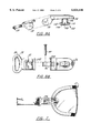
- FIG. 10 is a perspective view of the protective eyewear with adjustable strap of FIGS. 1-6 combined with a set of protective ear muffs and/or head phones snap locked respectively to each ear muff and/or head phone;
- FIG. 11 is a perspective view of the protective eyewear with adjustable strap of FIGS. 1-6 combined with a set of protective ear muffs and/or head phones snap locked to the headband of the protective ear muffs and/or head phones;
- FIG. 12 is a top view of the protective eyewear in an alternative embodiment of the invention.
- FIG. 13 is a rear view of the protective eyewear of FIG. 12.
- Device 10 is comprised of three main sections including an eyewear lens 12 (shown generally in FIG. 5), a pair of strap holding temples 14 and 16 (best shown in FIGS. 1, 3, 4 and 6), and an adjustable strap assembly 18 (best shown also in FIGS. 1 and 6).
- Lens 12 includes a resilient gasketing flange 22 which provides sealing around the periphery of the lens 20.
- Gasketing 22 is preferably a resilient foam.
- Lenses 12 are preferably the unitary, piano lenses depicted in FIGS. 13-15 of the aforementioned U.S. Ser. No. 08/641,901.
- lenses 12 may consist of any other suitable protective lenses (having an alternative shape) including but not limited to the lenses depicted in FIGS. 1-6 and 11-12 of U.S. Ser. No.: 08/641,901 or the lenses in the aforementioned U.S. Pat. Nos. 4,867,550; 4,741,611; 4,674,851; 4,859,048; 5,381,192 and 5,032,017.
- no frames are provided for lenses 12, alternatively, the present invention may include a frame surrounding all or a portion of the lenses.
- lens 12 is preferably a piano lens wherein the plano lens comprises a front surface curvature which is created by rotating an aspheric shape about an axis which is offset from an axis of the aspheric shape.
- the aspheric shape is an ellipse or at least is an aspheric shape, a segment of which has an elliptical arc. This elliptical arc is rotated about an axis spaced (offset) some distance from a major or minor axis of the ellipse.
- the ellipse is rotated about an axis spaced from and parallel to the major or minor axis of the ellipse, but in the same plane as the ellipse.
- the resulting surface of this preferred lens configuration will have a cross-section in the horizontal meridian which is a segment of an ellipse, and a cross-section in the vertical meridian which is a segment of a circle.
- a significant feature of the preferred lens configuration is that the surface generated is rotationally symmetric.
- eyewear made of safety glass or any other suitable material can be utilized in conformance with this invention.
- Resilient flange 22 may be comprised of one or a plurality of strips which are adhesively applied along the periphery of lenses 12 or may be directly molded onto the lens.
- the flange 22 may be a single strip in which case it can be run along the entire periphery of the lens including those portions of the nosepiece and the hinge.
- the flange is broken at the hinges of the temples for ease of closing the temples during storage (the flange may also be broken at the nosepiece as shown in FIG. 5 since it may not be required in that area).
- the foam flange 22 provides an important feature and advantage to the eyewear of the present invention.
- the foam flange 102 tends to minimize the probability of exposure of the wearer's eyes to particulates in a dusty, dirty work environment and/or in a similar dirty or dusty sports environment such as on a beach.
- the use of the foam flange 22 will substantially reduce those incidences of eye damage caused by floating particulates for people who wear the eyewear of FIGS. 1-6.
- the foam flange depicted in FIGS. 1-6 could also be used in connection with protective eyewear having a frame 25.
- Still another feature provided by the resilient flange of the present invention is that the flange, particularly by tailoring the softness and other characteristics of the foam, will improve the wearer's comfort, especially when the eyewear of this invention is worn for long periods of time.
- FIGS. 8A-8B and FIG. 7 show the adjustable strap holding element 28.
- Strap holding element 28 includes a temple hinge 32.
- the temple hinge 32 is pivotally coupled to the end piece 24 (shown best in FIG. 7 and FIGS. 8A-8B) with a pin 34 (best seen in FIG. 8B) inserted through hinge element 36 to form a pivotable joint between end piece 24 and strap holding element 28.
- end piece 24 and strap element 28 allows the temples 14,16 to fold one upon the other to enable the eyewear to take up minimum space when eyewear 10 is stored or not in use. This pivotal joint also acts to enhance the fit of the eyewear to the user's head by appropriately conforming the strap and eyewear as required.
- the material used for end piece 24 and strap holding element 28 is preferably a suitable moldable plastic.
- strap holding temples 14, 16 are connected directly to the upper, outer edges of the lens 12 (best seen in FIG. 7).
- lens 12 could just as well be connected to a frame instead of directly to a lens; in which case temples 14, 16 could be attached either to the lenses or to the frame.
- the end piece 24 includes a post shown generally at 102 including a cylindrical neck 104 and a head 106.
- the end piece 24 includes recesses 26 that engage projections 52 formed on the exterior surface of the lens 12 (shown in FIG. 8D).
- a groove 108 is formed in the head 106 and a portion of the neck 104.
- the groove 108 has a v-shape where the width of the groove at one end is greater than the width of the groove at the other end. It is understood that alternative geometries may be used for groove 108.
- the groove 108 is formed generally perpendicular to the longitudinal axis of head 106 and extends across the entire head 106.
- the lens 12 includes a slot 50 and projections 52 which cooperate with the end piece 24 to provide adjustment of the pantoscopic angle of the eyewear.
- Slot 50 is generally oval shaped and has a center circular area 51.
- Projections 52 are formed on the surface of the lens 12 and extend away from the lens surface.
- the recesses 26 engage projections 52 formed on lens 12. It is understood that projections may be formed on the end piece 24 and recesses formed in the lens 12.
- the end piece 24 is coupled to the lens 12 by inserting the post 102 through slot 50 and rotating the end piece 24.
- the wearer rotates the end piece 24 and aligns one pair of the recesses 26 with the projections 52 formed on the lens 12.
- the groove 108 allows the distal ends 110 and 112 along the longitudinal axis of the head 106 to flex away from the lens 12. This allows the end piece 24 to rotate within the lens 12 more easily. This is particularly useful when the end piece 24 is first rotated upon insertion of the end piece into the lens 12 and when the pantoscopic angle is adjusted.
- the end piece 24 is made from a resilient material and the distal ends 110 and 112 of the head 106 apply pressure to the lens 13 and hold the end piece 24 at the desired pantoscopic angle.
- pantoscopic angle features of the present invention are preferably identical to the pantascopic angle features of commonly assigned U.S. patent application Ser. No. 08/770,920 filed Dec. 20, 1996 (all of the contents of which are incorporated herein by reference) except that the temple length adjustment housing 70 and temple tip 80 are replaced by the strap holding elements 28 and strap assembly 18 in the present invention. Therefore, reference is made to the application U.S. Ser. No.: 08/770,920 for a additional details of the pantoscopic angle feature.
- the pantoscopic adjustment features assure for snug and comfortable fit especially when the protective eyewear of the present invention is combined with other safety devices.
- Strap holding element 28 has a smooth loop 38 sized to accept adjustable strap assembly 18.
- Adjustable strap assembly 18 (see FIGS. 9A-9B) is comprised of a right hand buckle and strap assembly generally shown at 40 and a left hand buckle and strap assembly generally shown at 42.
- Right hand buckle and strap assembly 40 is comprised of a suitable length of strap 44 and a snap-in female portion of buckle 46.
- left hand buckle assembly 42 is comprised of a suitable length of strap 48, the male portion of snap-in buckle 50 which mates with the female portion of buckle 46 and a known strap tightening fastener 52 for adjusting the left hand strap 48 to the desired position for a secure mounting of the eyewear on a person's head to assure a snug and comfortable fit.
- Strap portion 44 and strap portion 48 are suitably sized as is known in the industry and is preferably of known stretchable materials.
- Half buckle 46 and half buckle 50 and strap tightening fastener 52 are commercially available and should be of such material and finish as required by the environment where used. Both half buckle 46 and half buckle 50 have known snap connectors that snap into detents that exist on the outside of the safety ear muffs, head phones or any other safety device used in conjunction with the present invention eyewear.
- strap 48 is longer than strap 44 because the extra length of strapping is needed to provide adequate adjustment of the adjustable strap assembly 18. It should be further noted that the end 104 of right hand strap 44 is folded over the loop 106 of buckle (half) 46 and extends a suitable distance and is assembled to a portion of strap 44 by known methods such as adhesives, welding or other known means.
- FIG. 10 is a perspective view of the protective eyewear with adjustable strap 10 of FIGS. 1-6 in accordance with the present invention shown combined with a set of noise protective ear muffs and/or head phones generally shown at 56.
- Right hand buckle and strap assembly 40 has been unbuckled from left hand buckle and strap assembly 42. This allows right hand buckle and strap assembly 40 to be snap lockedly secured to the right ear muff of protective ear muff and/or head phones 56 and, likewise, left hand buckle and strap assemble 42 to be snap lockedly secured to the left ear muff of protective ear muff and/or head phones 56.
- this arrangement provides for a secure and comfortable fit without breaking the seal of the protective ear muffs as would be the case with ordinary protective eyewear equipped with conventional temples. It should be further noted that other protective gear such as a breathing mask could be added to this arrangement with no problems.
- the protective eyewear is snap lockedly secured to the headband 58 of the protective ear muff and/or head phones 56. It is understood that the protective eyewear 10 can be snap lockedly secured to any portion of the protective gear as long as the spatial relationship between the eyes and other portions of the wearer's head are maintained.
- FIG. 12 is a top view of the protective eyewear in an alternative embodiment of the invention. As shown in FIG. 12, the major portions of the protective eyewear are similar to those described above. In particular, the lens 12, temples 14, 16 and adjustable strap assembly 18 are the same as those described above with references to FIGS. 1-6. The gasketing 22, however, has been removed.
- FIG. 13 is a rear view of the protective eyewear of FIG. 12. The above described advantages of the temples 14 and 16 and the adjustable strap assembly 18 are still provided by the protective eyewear shown in FIGS. 12 and 13.
- an anti-fog coating is applied to the inner surface of lenses 12 to enhance optical viewing.
- attempts to create such seal against particulate matter entry to the eye area have failed because of inability of the prior art to resolve the problem of fogging when the eyewear was worn for any length of time.
- any suitable anti-fog coating can be used in accordance with this invention; however a preferred anti-fog coating is commercially sold by Aearo Corporation of Southbridge, Mass. under the DX trademark.
Abstract
Description
Claims (12)
Priority Applications (8)
| Application Number | Priority Date | Filing Date | Title |
|---|---|---|---|
| US08/806,595 US6024446A (en) | 1996-05-02 | 1997-02-26 | Eyewear with hingedly attached strapped head retainer |
| PCT/US1998/003766 WO1998038544A1 (en) | 1997-02-26 | 1998-02-26 | Protective eyewear with adjustable strap |
| US09/032,505 US6149268A (en) | 1996-05-02 | 1998-02-26 | Protective eyewear with at least one ventilation channel |
| AU64405/98A AU745798B2 (en) | 1997-02-26 | 1998-02-26 | Protective eyewear with adjustable strap |
| EP98910071A EP0919011A4 (en) | 1997-02-26 | 1998-02-26 | Protective eyewear with adjustable strap |
| CA002252672A CA2252672A1 (en) | 1997-02-26 | 1998-02-26 | Protective eyewear with adjustable strap |
| US09/474,045 US6511177B1 (en) | 1996-05-02 | 1999-12-28 | Protective eyewear with adjustable strap |
| US09/542,238 US6276795B1 (en) | 1996-05-02 | 2000-04-04 | Protective eyewear with adjustable strap |
Applications Claiming Priority (3)
| Application Number | Priority Date | Filing Date | Title |
|---|---|---|---|
| US64190196A | 1996-05-02 | 1996-05-02 | |
| US08/770,920 US5909267A (en) | 1996-05-02 | 1996-12-20 | Pantascopic adjustment mechanism for eyewear |
| US08/806,595 US6024446A (en) | 1996-05-02 | 1997-02-26 | Eyewear with hingedly attached strapped head retainer |
Related Parent Applications (2)
| Application Number | Title | Priority Date | Filing Date |
|---|---|---|---|
| US64190196A Continuation-In-Part | 1996-05-02 | 1996-05-02 | |
| US08/806,832 Continuation-In-Part US5825455A (en) | 1996-05-02 | 1997-02-26 | Aspheric plano eyewear |
Related Child Applications (2)
| Application Number | Title | Priority Date | Filing Date |
|---|---|---|---|
| US09/032,505 Continuation-In-Part US6149268A (en) | 1996-05-02 | 1998-02-26 | Protective eyewear with at least one ventilation channel |
| US09/474,045 Division US6511177B1 (en) | 1996-05-02 | 1999-12-28 | Protective eyewear with adjustable strap |
Publications (1)
| Publication Number | Publication Date |
|---|---|
| US6024446A true US6024446A (en) | 2000-02-15 |
Family
ID=25194398
Family Applications (2)
| Application Number | Title | Priority Date | Filing Date |
|---|---|---|---|
| US08/806,595 Expired - Lifetime US6024446A (en) | 1996-05-02 | 1997-02-26 | Eyewear with hingedly attached strapped head retainer |
| US09/474,045 Expired - Fee Related US6511177B1 (en) | 1996-05-02 | 1999-12-28 | Protective eyewear with adjustable strap |
Family Applications After (1)
| Application Number | Title | Priority Date | Filing Date |
|---|---|---|---|
| US09/474,045 Expired - Fee Related US6511177B1 (en) | 1996-05-02 | 1999-12-28 | Protective eyewear with adjustable strap |
Country Status (5)
| Country | Link |
|---|---|
| US (2) | US6024446A (en) |
| EP (1) | EP0919011A4 (en) |
| AU (1) | AU745798B2 (en) |
| CA (1) | CA2252672A1 (en) |
| WO (1) | WO1998038544A1 (en) |
Cited By (13)
| Publication number | Priority date | Publication date | Assignee | Title |
|---|---|---|---|---|
| WO2005030344A1 (en) * | 2003-10-01 | 2005-04-07 | Tecno Rubber S.R.L. | Diving and swimming mask |
| US6902272B2 (en) | 2001-07-13 | 2005-06-07 | Laura F. Woford | Soft wrap frames with interchangeable lenses |
| US6908194B1 (en) | 2000-09-20 | 2005-06-21 | Kevin B. Johnson | Eyeglasses with interchangeable and adjustable headband |
| US20050132478A1 (en) * | 2003-12-03 | 2005-06-23 | Canavan Richard W. | Detachable and rotatable clip |
| US20060010585A1 (en) * | 2004-06-23 | 2006-01-19 | Herman Chiang | Swimming goggles with strap adjusting device |
| US20070236650A1 (en) * | 2006-04-11 | 2007-10-11 | Anamika Jain | Eyeglasses |
| US20080256688A1 (en) * | 2007-04-18 | 2008-10-23 | Nike, Inc. | Article of Eyewear |
| US20090188015A1 (en) * | 2008-01-29 | 2009-07-30 | Timely Medical Innovations, Llc | Flip-to-wear eye shield |
| US8484762B2 (en) | 2011-09-09 | 2013-07-16 | Samuel A. Goldstein | Protective sports headgear |
| US9532617B2 (en) | 2014-02-21 | 2017-01-03 | Tidi Products, Llc | Disposable face shield |
| US20170354538A1 (en) * | 2016-06-13 | 2017-12-14 | Arthur Wang | Eyewear component with replaceable lens |
| US10973689B2 (en) * | 2018-09-17 | 2021-04-13 | Aswan International Corp. | Snow goggle device |
| US20220226154A1 (en) * | 2021-01-20 | 2022-07-21 | Finis Inc | Swim goggle |
Families Citing this family (18)
| Publication number | Priority date | Publication date | Assignee | Title |
|---|---|---|---|---|
| US6276795B1 (en) * | 1996-05-02 | 2001-08-21 | Aearo Company | Protective eyewear with adjustable strap |
| US6817068B2 (en) | 2003-01-02 | 2004-11-16 | The Burton Corporation | Adjustable length strap assembly |
| WO2004107023A1 (en) * | 2003-06-03 | 2004-12-09 | Pyo, Tae, Won | Custom frame for eyeglass lenses and instruments |
| US7020901B2 (en) * | 2003-07-21 | 2006-04-04 | Brhel Joseph A | Eye and ear protection apparatus |
| US20180104094A9 (en) * | 2008-05-16 | 2018-04-19 | Seth A. Biser | Thermal eye compress systems and methods of use |
| JP5502086B2 (en) * | 2008-08-25 | 2014-05-28 | ラウド・アンド・クリア・セイフティ・ピーティーワイ・リミテッド | Protective device |
| AU2009201810A1 (en) * | 2009-05-06 | 2010-11-25 | Jorge Miguel Pereira | Ear Muffs |
| US20110131709A1 (en) * | 2009-12-07 | 2011-06-09 | Fernando Caraballo | Safety system |
| US8621664B2 (en) | 2011-08-24 | 2014-01-07 | Donald Scott Peebles | Combination headgear and eye protection system |
| US9168176B2 (en) * | 2011-08-24 | 2015-10-27 | Donald Scott Peebles | Combination ear and eye protection system and related method |
| US9164293B2 (en) | 2011-10-24 | 2015-10-20 | Dolby Laboratories Licensing Corporation | Adjustable eyewear with fixed temple and method of manufacture |
| US9668921B2 (en) | 2012-04-24 | 2017-06-06 | Gregg Vollet | Ear-engaging and eye-covering head assembly |
| CA2798596C (en) | 2012-04-24 | 2014-04-22 | Gregg Vollet | Ear-engaging and eye-covering head assembly |
| US9256081B2 (en) | 2013-10-11 | 2016-02-09 | Warrior Sports, Inc. | Protective eyewear |
| US11679033B2 (en) * | 2019-10-15 | 2023-06-20 | Oakley, Inc. | Frameless goggle |
| CN111772924A (en) * | 2020-06-02 | 2020-10-16 | 倪鸿宁 | Epidemic prevention is with having epidemic prevention that dampproofing structure is convenient for wear and is used goggles |
| USD938381S1 (en) * | 2021-01-26 | 2021-12-14 | Shenzhen Lvkun Business Consulting Co., Ltd. | Music blindfold |
| USD946549S1 (en) * | 2021-05-14 | 2022-03-22 | Qiuhong Wang | Wireless headband |
Citations (65)
| Publication number | Priority date | Publication date | Assignee | Title |
|---|---|---|---|---|
| US289740A (en) * | 1883-12-04 | Thomas a | ||
| US836599A (en) * | 1905-12-05 | 1906-11-20 | Standard Optical Co | Mounting for eyeglasses. |
| US1032488A (en) * | 1907-09-06 | 1912-07-16 | Frank A Marcher | Mounting for eyeglasses. |
| US1119811A (en) * | 1912-06-19 | 1914-12-08 | American Optical Corp | Lens attachment. |
| US1181365A (en) * | 1915-06-29 | 1916-05-02 | Henry F Beaudry | Spectacles or eyeglasses. |
| US1189986A (en) * | 1915-09-03 | 1916-07-04 | Fredercik C Merry | Spectacle or eyeglass mounting. |
| US1217035A (en) * | 1916-03-13 | 1917-02-20 | Ernest L Mcdowell | Device for fitting eyeglass-lenses. |
| US1250703A (en) * | 1915-06-04 | 1917-12-18 | American Optical Corp | Lens-clip. |
| US1274870A (en) * | 1916-03-06 | 1918-08-06 | Daniel G Golding | Lens-mounting for eyeglasses. |
| US1278190A (en) * | 1915-02-20 | 1918-09-10 | Laurence C Martin | Eyeglass construction. |
| US1294390A (en) * | 1917-05-26 | 1919-02-18 | Alfred Burke | Spectacle-temple connection. |
| US2004005A (en) * | 1934-03-06 | 1935-06-04 | Michael R Mcdanal | Mounting for rimless spectacles and eyeglasses |
| US2537047A (en) * | 1947-11-17 | 1951-01-09 | Ernest B Gatten | Ophthalmic lens for spectacles affording increased field of vision |
| CA485155A (en) * | 1952-07-22 | Anthony Baratelli Charles | Ophthalmic device | |
| US2630569A (en) * | 1951-06-22 | 1953-03-10 | American Optical Corp | Eye protective device |
| FR1185637A (en) * | 1957-10-31 | 1959-08-03 | Improvements to so-called protective glasses | |
| FR1247974A (en) * | 1959-10-24 | 1960-12-09 | Vape Sa Ets | Panoramic sunglasses |
| US3218765A (en) * | 1962-08-22 | 1965-11-23 | Volk David | Lens generating method |
| US3233249A (en) * | 1963-07-16 | 1966-02-08 | Renauld Internat Inc | Fisherman's goggle |
| US3233250A (en) * | 1963-07-16 | 1966-02-08 | Renauld International Inc | Ski shield |
| US3283446A (en) * | 1965-10-05 | 1966-11-08 | Feinbloom William | Corneal contact lens tool |
| US3394980A (en) * | 1964-06-11 | 1968-07-30 | Safemaster Inc | Spectacles with adjustable length temples |
| US3526449A (en) * | 1967-11-09 | 1970-09-01 | Ritchard Salvage | One-piece sunglasses |
| US3544204A (en) * | 1969-06-12 | 1970-12-01 | Glendale Optical Co Inc | Adjustable temple for safety spectacles |
| US3605116A (en) * | 1968-02-27 | 1971-09-20 | Esb Inc | Industrial spectacles |
| US3623800A (en) * | 1969-10-16 | 1971-11-30 | David Volk | Ophthalmic lens of changing power |
| US3691565A (en) * | 1970-11-25 | 1972-09-19 | Omnitech Inc | Flight deck goggle |
| US3708224A (en) * | 1971-05-24 | 1973-01-02 | Textron Inc | Ventilated goggles |
| US3722986A (en) * | 1967-10-30 | 1973-03-27 | L Tagnon | High toric power ophthalmic lenses |
| US3907410A (en) * | 1973-11-27 | 1975-09-23 | Rex Richmond | Integral vertical plan adjusting mechanism for eye glasses |
| US3950082A (en) * | 1973-01-10 | 1976-04-13 | David Volk | Ophthalmic lens for presbyopia and aphakia |
| US4002439A (en) * | 1973-01-10 | 1977-01-11 | David Volk | Method of forming an ophthalmic lens for presbyopia and aphakia |
| US4240718A (en) * | 1978-01-26 | 1980-12-23 | Wicher Max F | Sports spectacle structure |
| US4564272A (en) * | 1983-03-18 | 1986-01-14 | Rinnooy Kan Edmond A | Eyeglasses with interchangeable parts |
| US4630906A (en) * | 1982-05-14 | 1986-12-23 | Carl-Zeiss-Stiftung | Blank for eyeglass lenses having ellipse-like edge curves and means and method for selecting |
| US4670915A (en) * | 1986-03-17 | 1987-06-09 | Evans Bradley J | Interchangeable eyeshield |
| US4674851A (en) * | 1985-01-11 | 1987-06-23 | Jannard James H | Removable multi-component sunglasses |
| US4683587A (en) * | 1985-06-11 | 1987-07-28 | Silverman Michael D | Submersible personal stereo |
| US4741611A (en) * | 1981-03-26 | 1988-05-03 | Pro-Tec, Inc. | Eyeglasses adapted for sports and protective use |
| US4786125A (en) * | 1983-08-22 | 1988-11-22 | Farrand Optical Co. | Ocular protective apparatus |
| US4810080A (en) * | 1987-09-03 | 1989-03-07 | American Optical Corporation | Protective eyewear with removable nosepiece and corrective spectacle |
| US4824233A (en) * | 1985-01-11 | 1989-04-25 | Jannard James H | Multi-component sunglasses |
| US4843655A (en) * | 1987-12-15 | 1989-07-04 | Alpina Int'l Sport + Optik-Vertriebs-Gmbh | Protective goggles |
| US4859048A (en) * | 1985-01-11 | 1989-08-22 | Oakley, Inc. | Cylindrical lens for sunglasses |
| US4867550A (en) * | 1985-01-11 | 1989-09-19 | Oakley, Inc. | Toroidal lens for sunglasses |
| US4955706A (en) * | 1988-09-30 | 1990-09-11 | Optyl Eyewear Fashion International Corporation | Composite polymeric spectacle parts |
| US4955087A (en) * | 1988-09-15 | 1990-09-11 | Richard Perez | Combined visor and sunglasses assembly |
| US4978182A (en) * | 1989-10-23 | 1990-12-18 | Kaiser Optical Systems | Laser protection visor with ellipsoidal geometry |
| US4977627A (en) * | 1988-10-18 | 1990-12-18 | American Optical Corporation | Protective goggle |
| US5032017A (en) * | 1988-07-26 | 1991-07-16 | Etablissements Bolle Georges, Robert Et Maurice | Spectacles comprising means for quickly fitting the side-pieces and the nose-piece |
| US5050981A (en) * | 1990-07-24 | 1991-09-24 | Johnson & Johnson Vision Products, Inc. | Lens design method and resulting aspheric lens |
| US5208614A (en) * | 1990-11-30 | 1993-05-04 | Oakley, Inc. | Concavely indented lenses for eyeware |
| US5235357A (en) * | 1990-11-08 | 1993-08-10 | American Optical Corporation | Spectacle lenses having an inside-out conicoidal front surface and method for forming same |
| US5278999A (en) * | 1993-02-17 | 1994-01-18 | Ronald Brown | Combined ear and eye protection device |
| US5357292A (en) * | 1992-05-26 | 1994-10-18 | Uvex Safety, Llc | Eyeglasses with adjustable temple inclination |
| US5381192A (en) * | 1991-08-07 | 1995-01-10 | Uvex Safety, Llc | Protective eyeglasses construction with adjustable temples |
| US5379463A (en) * | 1992-07-24 | 1995-01-10 | Hubert Greenway | Facial shield, particularly for protection from the sun |
| US5387949A (en) * | 1992-01-29 | 1995-02-07 | Oakley, Inc. | Eyeglass connection device |
| US5418581A (en) * | 1993-06-07 | 1995-05-23 | Bausch & Lomb Incorporated | Hinge system for eyewear |
| US5426473A (en) * | 1993-10-29 | 1995-06-20 | American Allsafe Company | Safety spectacles with temple hinge providing simultaneous adjustment of effective temple length and width between temples |
| US5511251A (en) * | 1994-11-03 | 1996-04-30 | Brakas; Yvonne J. | Head strap for sunglasses |
| US5519896A (en) * | 1995-04-13 | 1996-05-28 | Ford; Dan E. | Ventilated sport goggles |
| US5526070A (en) * | 1994-02-04 | 1996-06-11 | Killer Loop S.P.A. | Nose pad particularly for spectacle frames |
| US5659381A (en) * | 1993-12-03 | 1997-08-19 | Killer Loop S.P.A. | Engagement device particularly for lenses of eyeglasses |
| US5724119A (en) * | 1996-07-12 | 1998-03-03 | Howard S. Leight & Associates Inc. | Earmuff-eyeglass combination |
Family Cites Families (12)
| Publication number | Priority date | Publication date | Assignee | Title |
|---|---|---|---|---|
| FR2302718A1 (en) * | 1975-03-05 | 1976-10-01 | Bolle Robert | Cushioned frame racing goggles - have visor block of strong plastic with straps attached directly by pivot mountings |
| US4478558A (en) | 1980-08-04 | 1984-10-23 | D. W. Zimmerman Mfg., Inc. | Downhole pump with check valve |
| USD270165S (en) | 1981-02-25 | 1983-08-16 | Pro-Tec, Inc. | Eyeglasses |
| USD323333S (en) | 1989-08-22 | 1992-01-21 | Oakley, Inc. | Eyeglasses |
| FR2670588A1 (en) * | 1990-12-12 | 1992-06-19 | Bonnin Claude | MODULAR EYEWEAR / MASKS WITH ADJUSTMENT AND / OR ORIENTATION MEANS OF TOOLS WITHOUT TOOLS. |
| USD354067S (en) | 1992-05-22 | 1995-01-03 | Carrera Eyewear Corporation | Eyeglasses |
| USD358828S (en) | 1993-09-22 | 1995-05-30 | Oakley, Inc. | Lens and connectors |
| US5457503B1 (en) * | 1994-12-08 | 1997-07-01 | Jimmy Chen | Spectacles with high efficient angle adjustment |
| US5636388A (en) * | 1994-12-27 | 1997-06-10 | Hodges; Robert | Goggles |
| US5617588A (en) * | 1995-03-16 | 1997-04-08 | Uvex Safety, Inc. | Snap together protective goggle construction with toric lens |
| IT1279315B1 (en) * | 1995-06-14 | 1997-12-09 | Killer Loop Spa | INTERCONNECTION DEVICE, PARTICULARLY FOR GLASSES |
| US5706360A (en) * | 1995-11-27 | 1998-01-06 | Khandekar; Pramod | Headset with spectacle temple accommodating openings |
-
1997
- 1997-02-26 US US08/806,595 patent/US6024446A/en not_active Expired - Lifetime
-
1998
- 1998-02-26 WO PCT/US1998/003766 patent/WO1998038544A1/en not_active Application Discontinuation
- 1998-02-26 EP EP98910071A patent/EP0919011A4/en not_active Withdrawn
- 1998-02-26 CA CA002252672A patent/CA2252672A1/en not_active Abandoned
- 1998-02-26 AU AU64405/98A patent/AU745798B2/en not_active Ceased
-
1999
- 1999-12-28 US US09/474,045 patent/US6511177B1/en not_active Expired - Fee Related
Patent Citations (66)
| Publication number | Priority date | Publication date | Assignee | Title |
|---|---|---|---|---|
| CA485155A (en) * | 1952-07-22 | Anthony Baratelli Charles | Ophthalmic device | |
| US289740A (en) * | 1883-12-04 | Thomas a | ||
| US836599A (en) * | 1905-12-05 | 1906-11-20 | Standard Optical Co | Mounting for eyeglasses. |
| US1032488A (en) * | 1907-09-06 | 1912-07-16 | Frank A Marcher | Mounting for eyeglasses. |
| US1119811A (en) * | 1912-06-19 | 1914-12-08 | American Optical Corp | Lens attachment. |
| US1278190A (en) * | 1915-02-20 | 1918-09-10 | Laurence C Martin | Eyeglass construction. |
| US1250703A (en) * | 1915-06-04 | 1917-12-18 | American Optical Corp | Lens-clip. |
| US1181365A (en) * | 1915-06-29 | 1916-05-02 | Henry F Beaudry | Spectacles or eyeglasses. |
| US1189986A (en) * | 1915-09-03 | 1916-07-04 | Fredercik C Merry | Spectacle or eyeglass mounting. |
| US1274870A (en) * | 1916-03-06 | 1918-08-06 | Daniel G Golding | Lens-mounting for eyeglasses. |
| US1217035A (en) * | 1916-03-13 | 1917-02-20 | Ernest L Mcdowell | Device for fitting eyeglass-lenses. |
| US1294390A (en) * | 1917-05-26 | 1919-02-18 | Alfred Burke | Spectacle-temple connection. |
| US2004005A (en) * | 1934-03-06 | 1935-06-04 | Michael R Mcdanal | Mounting for rimless spectacles and eyeglasses |
| US2537047A (en) * | 1947-11-17 | 1951-01-09 | Ernest B Gatten | Ophthalmic lens for spectacles affording increased field of vision |
| US2630569A (en) * | 1951-06-22 | 1953-03-10 | American Optical Corp | Eye protective device |
| FR1185637A (en) * | 1957-10-31 | 1959-08-03 | Improvements to so-called protective glasses | |
| FR1247974A (en) * | 1959-10-24 | 1960-12-09 | Vape Sa Ets | Panoramic sunglasses |
| US3218765A (en) * | 1962-08-22 | 1965-11-23 | Volk David | Lens generating method |
| US3233249A (en) * | 1963-07-16 | 1966-02-08 | Renauld Internat Inc | Fisherman's goggle |
| US3233250A (en) * | 1963-07-16 | 1966-02-08 | Renauld International Inc | Ski shield |
| US3394980A (en) * | 1964-06-11 | 1968-07-30 | Safemaster Inc | Spectacles with adjustable length temples |
| US3283446A (en) * | 1965-10-05 | 1966-11-08 | Feinbloom William | Corneal contact lens tool |
| US3722986A (en) * | 1967-10-30 | 1973-03-27 | L Tagnon | High toric power ophthalmic lenses |
| US3526449A (en) * | 1967-11-09 | 1970-09-01 | Ritchard Salvage | One-piece sunglasses |
| US3605116A (en) * | 1968-02-27 | 1971-09-20 | Esb Inc | Industrial spectacles |
| US3544204A (en) * | 1969-06-12 | 1970-12-01 | Glendale Optical Co Inc | Adjustable temple for safety spectacles |
| US3623800A (en) * | 1969-10-16 | 1971-11-30 | David Volk | Ophthalmic lens of changing power |
| US3691565A (en) * | 1970-11-25 | 1972-09-19 | Omnitech Inc | Flight deck goggle |
| US3708224A (en) * | 1971-05-24 | 1973-01-02 | Textron Inc | Ventilated goggles |
| US3950082A (en) * | 1973-01-10 | 1976-04-13 | David Volk | Ophthalmic lens for presbyopia and aphakia |
| US4002439A (en) * | 1973-01-10 | 1977-01-11 | David Volk | Method of forming an ophthalmic lens for presbyopia and aphakia |
| US3907410A (en) * | 1973-11-27 | 1975-09-23 | Rex Richmond | Integral vertical plan adjusting mechanism for eye glasses |
| US4240718A (en) * | 1978-01-26 | 1980-12-23 | Wicher Max F | Sports spectacle structure |
| US4741611A (en) * | 1981-03-26 | 1988-05-03 | Pro-Tec, Inc. | Eyeglasses adapted for sports and protective use |
| US4630906A (en) * | 1982-05-14 | 1986-12-23 | Carl-Zeiss-Stiftung | Blank for eyeglass lenses having ellipse-like edge curves and means and method for selecting |
| US4564272A (en) * | 1983-03-18 | 1986-01-14 | Rinnooy Kan Edmond A | Eyeglasses with interchangeable parts |
| US4786125A (en) * | 1983-08-22 | 1988-11-22 | Farrand Optical Co. | Ocular protective apparatus |
| US4674851A (en) * | 1985-01-11 | 1987-06-23 | Jannard James H | Removable multi-component sunglasses |
| US4824233A (en) * | 1985-01-11 | 1989-04-25 | Jannard James H | Multi-component sunglasses |
| US4859048A (en) * | 1985-01-11 | 1989-08-22 | Oakley, Inc. | Cylindrical lens for sunglasses |
| US4867550A (en) * | 1985-01-11 | 1989-09-19 | Oakley, Inc. | Toroidal lens for sunglasses |
| US4683587A (en) * | 1985-06-11 | 1987-07-28 | Silverman Michael D | Submersible personal stereo |
| US4670915A (en) * | 1986-03-17 | 1987-06-09 | Evans Bradley J | Interchangeable eyeshield |
| US4810080A (en) * | 1987-09-03 | 1989-03-07 | American Optical Corporation | Protective eyewear with removable nosepiece and corrective spectacle |
| US4843655A (en) * | 1987-12-15 | 1989-07-04 | Alpina Int'l Sport + Optik-Vertriebs-Gmbh | Protective goggles |
| US5032017A (en) * | 1988-07-26 | 1991-07-16 | Etablissements Bolle Georges, Robert Et Maurice | Spectacles comprising means for quickly fitting the side-pieces and the nose-piece |
| US4955087A (en) * | 1988-09-15 | 1990-09-11 | Richard Perez | Combined visor and sunglasses assembly |
| US4955706A (en) * | 1988-09-30 | 1990-09-11 | Optyl Eyewear Fashion International Corporation | Composite polymeric spectacle parts |
| US4977627A (en) * | 1988-10-18 | 1990-12-18 | American Optical Corporation | Protective goggle |
| US4978182A (en) * | 1989-10-23 | 1990-12-18 | Kaiser Optical Systems | Laser protection visor with ellipsoidal geometry |
| US5050981A (en) * | 1990-07-24 | 1991-09-24 | Johnson & Johnson Vision Products, Inc. | Lens design method and resulting aspheric lens |
| US5235357A (en) * | 1990-11-08 | 1993-08-10 | American Optical Corporation | Spectacle lenses having an inside-out conicoidal front surface and method for forming same |
| US5208614A (en) * | 1990-11-30 | 1993-05-04 | Oakley, Inc. | Concavely indented lenses for eyeware |
| US5457505A (en) * | 1991-08-07 | 1995-10-10 | Uvex Safety, Inc. | Protective eyeglasses construction |
| US5381192A (en) * | 1991-08-07 | 1995-01-10 | Uvex Safety, Llc | Protective eyeglasses construction with adjustable temples |
| US5387949A (en) * | 1992-01-29 | 1995-02-07 | Oakley, Inc. | Eyeglass connection device |
| US5357292A (en) * | 1992-05-26 | 1994-10-18 | Uvex Safety, Llc | Eyeglasses with adjustable temple inclination |
| US5379463A (en) * | 1992-07-24 | 1995-01-10 | Hubert Greenway | Facial shield, particularly for protection from the sun |
| US5278999A (en) * | 1993-02-17 | 1994-01-18 | Ronald Brown | Combined ear and eye protection device |
| US5418581A (en) * | 1993-06-07 | 1995-05-23 | Bausch & Lomb Incorporated | Hinge system for eyewear |
| US5426473A (en) * | 1993-10-29 | 1995-06-20 | American Allsafe Company | Safety spectacles with temple hinge providing simultaneous adjustment of effective temple length and width between temples |
| US5659381A (en) * | 1993-12-03 | 1997-08-19 | Killer Loop S.P.A. | Engagement device particularly for lenses of eyeglasses |
| US5526070A (en) * | 1994-02-04 | 1996-06-11 | Killer Loop S.P.A. | Nose pad particularly for spectacle frames |
| US5511251A (en) * | 1994-11-03 | 1996-04-30 | Brakas; Yvonne J. | Head strap for sunglasses |
| US5519896A (en) * | 1995-04-13 | 1996-05-28 | Ford; Dan E. | Ventilated sport goggles |
| US5724119A (en) * | 1996-07-12 | 1998-03-03 | Howard S. Leight & Associates Inc. | Earmuff-eyeglass combination |
Cited By (19)
| Publication number | Priority date | Publication date | Assignee | Title |
|---|---|---|---|---|
| US6908194B1 (en) | 2000-09-20 | 2005-06-21 | Kevin B. Johnson | Eyeglasses with interchangeable and adjustable headband |
| US6902272B2 (en) | 2001-07-13 | 2005-06-07 | Laura F. Woford | Soft wrap frames with interchangeable lenses |
| WO2005030344A1 (en) * | 2003-10-01 | 2005-04-07 | Tecno Rubber S.R.L. | Diving and swimming mask |
| US20050132478A1 (en) * | 2003-12-03 | 2005-06-23 | Canavan Richard W. | Detachable and rotatable clip |
| US7003811B2 (en) * | 2003-12-03 | 2006-02-28 | Bacou-Dalloz Eye & Face Protection, Inc. | Detachable and rotatable clip |
| US20060010585A1 (en) * | 2004-06-23 | 2006-01-19 | Herman Chiang | Swimming goggles with strap adjusting device |
| US7007311B2 (en) * | 2004-06-23 | 2006-03-07 | Herman Chiang | Swimming goggles with strap adjusting device |
| US7341342B2 (en) | 2006-04-11 | 2008-03-11 | Anamika Jain | Eyeglasses |
| US20070236650A1 (en) * | 2006-04-11 | 2007-10-11 | Anamika Jain | Eyeglasses |
| US20080256688A1 (en) * | 2007-04-18 | 2008-10-23 | Nike, Inc. | Article of Eyewear |
| US20090188015A1 (en) * | 2008-01-29 | 2009-07-30 | Timely Medical Innovations, Llc | Flip-to-wear eye shield |
| US8214921B2 (en) * | 2008-01-29 | 2012-07-10 | Tidi Products, Llc | Flip-to-wear eye shield |
| US8458813B2 (en) * | 2008-01-29 | 2013-06-11 | Tidi Products, Llc | Flip-to-wear eye shield |
| US8707462B2 (en) | 2008-01-29 | 2014-04-29 | Tidi Products, Llc | Hinged eye shield |
| US8484762B2 (en) | 2011-09-09 | 2013-07-16 | Samuel A. Goldstein | Protective sports headgear |
| US9532617B2 (en) | 2014-02-21 | 2017-01-03 | Tidi Products, Llc | Disposable face shield |
| US20170354538A1 (en) * | 2016-06-13 | 2017-12-14 | Arthur Wang | Eyewear component with replaceable lens |
| US10973689B2 (en) * | 2018-09-17 | 2021-04-13 | Aswan International Corp. | Snow goggle device |
| US20220226154A1 (en) * | 2021-01-20 | 2022-07-21 | Finis Inc | Swim goggle |
Also Published As
| Publication number | Publication date |
|---|---|
| AU745798B2 (en) | 2002-04-11 |
| AU6440598A (en) | 1998-09-18 |
| WO1998038544A1 (en) | 1998-09-03 |
| EP0919011A4 (en) | 2001-01-31 |
| EP0919011A1 (en) | 1999-06-02 |
| CA2252672A1 (en) | 1998-09-03 |
| US6511177B1 (en) | 2003-01-28 |
Similar Documents
| Publication | Publication Date | Title |
|---|---|---|
| US6024446A (en) | Eyewear with hingedly attached strapped head retainer | |
| US6149268A (en) | Protective eyewear with at least one ventilation channel | |
| WO1998038544A9 (en) | Protective eyewear with adjustable strap | |
| CA2377390C (en) | Protective eyewear with adjustable strap | |
| US5191364A (en) | Protective eyewear for use in sports and the like | |
| US5862530A (en) | Protective eyewear with frame and detachable lens | |
| US4810080A (en) | Protective eyewear with removable nosepiece and corrective spectacle | |
| US6019469A (en) | Aspheric plano eyewear | |
| US4391498A (en) | Spectacle frame | |
| US5969787A (en) | Eyewear with browbar ventilation and detachable temples | |
| US5133596A (en) | Eye and hearing protection | |
| US6666554B2 (en) | Protective eyewear kit | |
| US7020901B2 (en) | Eye and ear protection apparatus | |
| KR100857295B1 (en) | A protective sideshield removably attachable to an eyeglass frame | |
| AU754177B2 (en) | Protective eyewear with adjustable strap | |
| US7407282B1 (en) | Eyeglass temple assembly | |
| JP3092724U (en) | Post-operative safety glasses | |
| CN112716690A (en) | Multifunctional goggles | |
| MXPA00001510A (en) | Ventilated browbar frame and eyewear | |
| JPH11267235A (en) | Common spectacle mounting full face mask |
Legal Events
| Date | Code | Title | Description |
|---|---|---|---|
| AS | Assignment |
Owner name: CABOT SAFETY INTERMEDIATE CORPORATION, MASSACHUSET Free format text: ASSIGNMENT OF ASSIGNORS INTEREST;ASSIGNORS:HALL, JAMES;FECTEAU, KEITH;DESY, RAOUL;AND OTHERS;REEL/FRAME:008599/0997;SIGNING DATES FROM 19970306 TO 19970307 |
|
| STCF | Information on status: patent grant |
Free format text: PATENTED CASE |
|
| CC | Certificate of correction | ||
| AS | Assignment |
Owner name: BANKERS TRUST COMPANY, NEW YORK Free format text: SECURITY INTEREST;ASSIGNOR:CABOT SAFETY INTERMEDIATE CORPORATION;REEL/FRAME:012075/0227 Effective date: 20010713 |
|
| FPAY | Fee payment |
Year of fee payment: 4 |
|
| AS | Assignment |
Owner name: DEUTSCHE BANK AG, NEW YORK BRANCH, NEW YORK Free format text: SECURITY AGREEMENT;ASSIGNOR:CABOT SAFETY INTERMEDIATE CORPORATION;REEL/FRAME:015293/0386 Effective date: 20040420 Owner name: CABOT SAFETY INTERMEDIATE CORPORATION, DELAWARE Free format text: PATENT RELEASE;ASSIGNOR:DEUTSCHE BANK TRUST COMPANY AMERICAS;REEL/FRAME:015302/0494 Effective date: 20040420 Owner name: DEUTSCHE BANK AG, NEW YORK BRANCH,NEW YORK Free format text: SECURITY AGREEMENT;ASSIGNOR:CABOT SAFETY INTERMEDIATE CORPORATION;REEL/FRAME:015293/0386 Effective date: 20040420 |
|
| AS | Assignment |
Owner name: CABOT SAFETY INTERMEDIATE CORPORATION,NORTH CAROLI Free format text: RELEASE OF SECURITY INTEREST;ASSIGNOR:DEUTSCHE BANK AG, NEW YORK BRANCH;REEL/FRAME:017626/0347 Effective date: 20060324 Owner name: CABOT SAFETY INTERMEDIATE CORPORATION, NORTH CAROL Free format text: RELEASE OF SECURITY INTEREST;ASSIGNOR:DEUTSCHE BANK AG, NEW YORK BRANCH;REEL/FRAME:017626/0347 Effective date: 20060324 |
|
| AS | Assignment |
Owner name: BANK OF AMERICA, N.A., AS FIRST LIEN COLLATERAL AG Free format text: SECURITY AGREEMENT;ASSIGNOR:CABOT SAFETY INTERMEDIATE CORPORATION;REEL/FRAME:017435/0721 Effective date: 20060324 Owner name: BANK OF AMERICA, N.A., AS SECOND LIEN COLLATERAL A Free format text: SECURITY AGREEMENT;ASSIGNOR:CABOT SAFETY INTERMEDIATE CORPORATION;REEL/FRAME:017435/0764 Effective date: 20060324 |
|
| AS | Assignment |
Owner name: CABOT SAFETY INTERMEDIATE CORPORATION,NORTH CAROLI Free format text: RELEASE OF SECURITY INTEREST;ASSIGNOR:DEUTSCHE BANK AG, NEW YORK BRANCH;REEL/FRAME:017663/0508 Effective date: 20060324 Owner name: CABOT SAFETY INTERMEDIATE CORPORATION, NORTH CAROL Free format text: RELEASE OF SECURITY INTEREST;ASSIGNOR:DEUTSCHE BANK AG, NEW YORK BRANCH;REEL/FRAME:017663/0508 Effective date: 20060324 |
|
| AS | Assignment |
Owner name: BANK OF AMERICA, N.A., AS FIRST LIEN COLLATERAL AG Free format text: GRANT OF FIRST LIEN SECURITY INTEREST IN UNITED STATES PATENTS AND TRADEMARKS;ASSIGNOR:CABOT SAFETY INTERMEDIATE CORPORATION;REEL/FRAME:019520/0001 Effective date: 20070601 Owner name: CABOT SAFETY INTERMEDIATE CORPORATION, DELAWARE Free format text: RELEASE OF FIRST LIEN SECURITY INTEREST AT REEL/FRAME NO. 17435/0721;ASSIGNOR:BANK OF AMERICA, N.A., AS FIRST LIEN COLLATERAL AGENT;REEL/FRAME:019511/0914 Effective date: 20070601 Owner name: CABOT SAFETY INTERMEDIATE CORPORATION,DELAWARE Free format text: RELEASE OF FIRST LIEN SECURITY INTEREST AT REEL/FRAME NO. 17435/0721;ASSIGNOR:BANK OF AMERICA, N.A., AS FIRST LIEN COLLATERAL AGENT;REEL/FRAME:019511/0914 Effective date: 20070601 |
|
| FPAY | Fee payment |
Year of fee payment: 8 |
|
| AS | Assignment |
Owner name: CABOT SAFETY INTERMEDIATE CORPORATION, DELAWARE Free format text: RELEASE OF FIRST LIEN SECURITY INTEREST AT REEL/FRAME NO. 19520/0001;ASSIGNOR:BANK OF AMERICA, N.A.;REEL/FRAME:020733/0440 Effective date: 20080401 Owner name: CABOT SAFETY INTERMEDIATE CORPORATION, DELAWARE Free format text: RELEASE OF SECOND LIEN SECURITY INTEREST AT REEL/FRAME NO. 17435/0764;ASSIGNOR:BANK OF AMERICA, N.A.;REEL/FRAME:020733/0510 Effective date: 20080401 Owner name: CABOT SAFETY INTERMEDIATE CORPORATION,DELAWARE Free format text: RELEASE OF SECOND LIEN SECURITY INTEREST AT REEL/FRAME NO. 17435/0764;ASSIGNOR:BANK OF AMERICA, N.A.;REEL/FRAME:020733/0510 Effective date: 20080401 Owner name: CABOT SAFETY INTERMEDIATE CORPORATION,DELAWARE Free format text: RELEASE OF FIRST LIEN SECURITY INTEREST AT REEL/FRAME NO. 19520/0001;ASSIGNOR:BANK OF AMERICA, N.A.;REEL/FRAME:020733/0440 Effective date: 20080401 |
|
| AS | Assignment |
Owner name: CABOT SAFETY INTERMEDIATE, LLC, DELAWARE Free format text: CHANGE OF NAME;ASSIGNOR:CABOT SAFETY INTERMEDIATE CORPORATION;REEL/FRAME:021976/0834 Effective date: 20080926 |
|
| AS | Assignment |
Owner name: 3M INNOVATIVE PROPERTIES COMPANY, MINNESOTA Free format text: ASSIGNMENT OF ASSIGNORS INTEREST;ASSIGNOR:CABOT SAFETY INTERMEDIATE LLC;REEL/FRAME:022052/0076 Effective date: 20081208 |
|
| FPAY | Fee payment |
Year of fee payment: 12 |